


REV. B 06/14
TJERNLUND PRODUCTS, INC.
1601 Ninth Street • White Bear Lake, MN 55110-6794
PHONE (651) 426-2993 • Technical Assistance (800) 255-4208 • FAX (651) 426-9547 Visit our web site • www.tjernlund.com
MODEL *GPAK-1TR*
FOR USE ON THE FOLLOWING - RHEEM, RUUD, WEATHERKING, SURE COMFORT, DUROGUARD AND THERMAL ZONE MODEL SERIES FURNACES:
(-)GDG* |
(-)GDJ* |
(-)GVH* |
(-)GPH* |
(-)GLG |
(-)GLH* |
(-)GVG |
(-)GLJ* |
(-)GPK* |
(-)GLN* |
(-)GPJ* |
(-)GVJ* |
(-)GDC |
(-)GLC |
(-)GDE |
(-)GLE |
(-)GVC |
(-)GYC |
(-)GLK* |
(-)GPP* |
(-)GVA |
(-)GYA |
(-)GVB |
(-)GYB |
WGVAH |
WGVAG |
WGDAG |
WGLAG |
(-)GPN* |
(-)GPQ* |
(-)GLQ* |
(-)GPR* |
(-)GLR* |
80PS* |
80LS* |
(-)GPS* |
(-)GLS* |
(-)GPT* |
(-)GLT* |
(-)GPE* |
(-)801* |
(-)802* |
TZ80MS* |
TZ80MD* |
TZ80DS* |
TZ80DD* |
|
|
|
|
*Indicated models are CSA certified with the *GPAK-1TR* as a vent system.
INDICATED 45,000 AND 67,500 BTU FURNACES MUST NOT BE AUXILIARY POWER VENTED UNLESS THE ORIGINAL VENT PRESSURE SWITCH IS REPLACED WITH A .30 VENT PRESSURE SWITCH, PART NO. 42-24064-01. FAILURE TO REPLACE THE PRESSURE SWITCH AS SPECIFIED COULD LEAD TO IMPROPER OPERATION OF THE FURNACE RESULTING IN PROPERTY DAMAGE, PERSONAL INJURY OR DEATH.
THE MODEL *GPAK-1TR* KIT INCLUDES:
1 - POWER VENTER
1 - VENT HOOD
1 - 4” BAROMETRIC DRAFT CONTROL
OWNER INSTRUCTIONS, DO NOT DESTROY
! Recognize this symbol as an indication of important Safety Information!
NOTE: FLUE GAS TEMPERATURES MUST NOT EXCEED
600oF AT POWER VENTER INLET.
! ____________________________________________________________________________
THESE INSTRUCTIONS ARE INTENDED AS AN AID TO QUALIFIED, LICENSED SERVICE PERSONNEL FOR PROPER INSTALLATION, ADJUSTMENT AND OPERATION OF THIS UNIT. READ THESE INSTRUCTIONS THOROUGHLY BEFORE ATTEMPTING INSTALLATION OR OPERATION. FAILURE TO FOLLOW THESE INSTRUCTIONS MAY RESULT IN IMPROPER INSTALLATION, ADJUSTMENT, SERVICE OR MAINTENANCE POSSIBLY RESULTING IN FIRE, ELECTRICAL SHOCK, CARBON MONOXIDE POISONING, EXPLOSION, PERSONAL INJURY OR PROPERTY DAMAGE.
DO NOT DESTROY. PLEASE READ CAREFULLY AND
KEEP IN A SAFE PLACE FOR FUTURE REFERENCE.
Copyright © 2014, Tjernlund Products, Inc. All rights reserved. |
P/N: 8504047 |

Tjernlund Products welcomes your comments and questions. Call us at 1-800-255-4208 or write to: |
|
Customer Service, Tjernlund Products, Inc., 1601 Ninth Street, White Bear Lake, MN |
55110-6794. |
TABLE OF CONTENTS |
|
|
PAGE(S) |
*GPAK-1TR* DESCRIPTION ....................................................................................................................................... |
1 |
SPECIFICATIONS .......................................................................................................................................................... |
1 |
*GPAK-1TR* SIZING ..................................................................................................................................................... |
2 |
INSTALLATION RESTRICTIONS ............................................................................................................................. |
2, 3 |
INSTALLER NOTES .................................................................................................................................................. |
3, 4 |
VENT HOOD LOCATION & INSTALLATION ............................................................................................................ |
4, 5 |
POWER VENTER INSTALLATION ....................................................................................................................... |
5, 6, 7 |
ELECTRICAL WIRING .............................................................................................................................................. |
7, 8 |
INSTALLATION RESTRICTIONS ................................................................................................................. |
7, 8 |
SEQUENCE OF OPERATION .......................................................................................................................... |
8 |
WIRING DIAGRAM ........................................................................................................................................... |
8 |
OPERATION CIRCUIT CHECK ...................................................................................................................... |
9 |
COMBUSTION AIR ......................................................................................................................................................... |
9 |
DRAFT ADJUSTMENT, SAFETY INTERLOCK & COMBUSTION AIR TEST ............................................................. |
9 |
MAINTENANCE ............................................................................................................................................................ |
9 |
TROUBLESHOOTING............................................................................................................................................. |
10, 11 |
WARRANTY & REPLACEMENT PARTS ................................................................................................................ |
11, 12 |
PERFORMANCE CURVE ............................................................................................................................................ |
12 |
INSTALLER NOTES ...................................................................................................................................................... |
13 |
VENT HOOD MOUNTING TEMPLATE ........................................................................................................................ |
14 |
*GPAK-1TR* DESCRIPTION
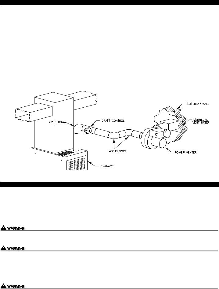
The *GPAK-1TR* is a complete venting system designed to side wall vent, Natural and LP gas furnaces. Each *GPAK-1TR* comes with three major components: Power Venter, Vent Hood and Draft Control. The *GPAK-1TR* can handle a maximum BTU/HR input of 150,000. The “T” of the *GPAK-1TR* indicates these kits have a post purge Relay/Timer which allows the Power Venter to continue operating for a nonadjustable period of approximately 45 seconds after the furnace burner shuts off.
SPECIFICATIONS
ELECTRICAL SPECIFICATIONS
POWER VENTER
*GPAK-1TR*
VENT HOOD
1
*GPAK-1TR* SIZING
Verify that the *GPAK-1TR* you are about to install is properly applied to the furnace.
When installing the *GPAK-1TR*, confirm that the BTU input of the furnace is 150,000 or less. All BTU/hr. capacity ranges are based on a maximum of 30 linear feet of vent pipe with no more than 3 elbows. All furnaces have a 3” flue connection as shipped from the factory. Use 4” pipe and use a 3” to 4” transition at the furnace.
WARNING: NO 34 INCH 80+ FURNACES WITH 45,000 OR 67,500 BTU INPUT CAN BE USED WITH ANY AUXILIARY POWER VENTER UNLESS THE FURNACE’S ORIGINAL 0.10 W.C. PRESSURE SWITCH, (PART NUMBER 42-24064-03) IS REPLACED WITH A 0.30 W.C. PRESSURE SWITCH, (PART NUMBER 42-24064-01).
1.All vent materials located between the furnace and the power venter inlet must be type “B” double wall vent pipe.
2.Single wall reducer(s) may be used to connect a barometric damper to the double wall vent pipe.
3.If the power venter is not directly connected to the inlet of the Power Venter Vent Hood, a sealed vent pipe must be used between the power venter outlet and the vent hood inlet. SEE *GPAK-1TR* POWER VENTER INSTALLATION AND OPERATION INSTRUCTIONS FOR ADDITIONAL INFORMATION.
COMMON INSTALLATION
NOTE: ALL VENT PIPE MUST BE TYPE “B” VENT
INSTALLATION RESTRICTIONS
Do not install the Power Venter on an appliance with an automatic valve having a manual opener unless the manual opener has been rendered inoperative or the automatic valve has been replaced with a valve not equipped with a manual opener.
IMPORTANT: UNDER NO CIRCUMSTANCES CAN ANY STANDING PILOT FURNACE BE HORIZONTALLY VENTED.
UNDER NO CIRCUMSTANCES CAN A FURNACE EQUIPPED WITH A NATURAL DRAFT DIVERTER BE HORIZONTALLY VENTED.
Failure to install, maintain and/or operate the Power Venter in accordance with manufacturer's instructions may result in conditions which can produce bodily injury and property damage.
The Power Venter must be installed by a qualified installer in accordance with these instructions and all local codes or in their absence in accordance with the latest edition of The National Fuel Gas Code (NFPA #54), The latest edition of the National Electrical Code (NFPA#70) and the Occupational Safety and Health Act (OSHA) when applicable. Canadian installations must be installed in accordance with CAN/CGA-B149 and the Canadian Electrical Code Part-1CSA Standard C22.1, Local installation codes and authorities having jurisdiction. Improper installation can create a hazardous condition such as an explosion, fire, electrical shock or carbon monoxide poisoning resulting in property damage, personal injury or death.
Flue gas temperatures must not exceed 600 degrees F. at the Power Venter inlet. Ambient temperatures must not exceed 104 degrees F. Temperatures above this range can cause a fire resulting in property damage, personal injury or death.
2
Disconnect the power supply when making wiring connections or when working around the fan wheel and motor. Failure to do so can result in electrical shock, personal injury, death or property damage.
1.“Qualified Installer” shall mean an individual properly trained and licensed
2.The installer must write or imprint name, phone number, date of installation and sign in the appropriate space on the Power Venter nameplate.
3.All vent pipe must be Type “B”. Plan the vent system so that Code required distances are maintained from plumbing and wiring.
4.The Power Venter motor shaft must be mounted horizontally to ensure proper operation of the Fan Proving Switch and prevent motor bearing wear.
5.Make certain the power supply is adequate for the fan motor requirements. Do not add the Power Venter to a circuit where the total load is unknown.
6.The installer must verify that the BTU/hr. input of the appliance does not exceed the recommended input of the *GPAK-1TR*. See “*GPAK-1TR* SIZING” on page 2 of these instructions for sizing information.
7.A safety inspection of an existing appliance must be performed before installation of the *GPAK-1TR* as outlined below from ANSI Z223.1/NFPA #54, Appendix H.
Improper installation, adjustment, alterations, service or maintenance can cause injury or property damage. Refer to this manual. For assistance or additional information consult a qualified installer, service agency or the gas supplier.
*SAFETY INSPECTION OF A PREVIOUSLY USED GAS APPLIANCE
(Perform prior to *GPAK-1TR* installation)
The following procedure is intended as a guide to aid in determining that an appliance is properly installed and is in safe condition for continuing use.
The following procedure is based on central specified gas furnace installations and it should be recognized that generalized procedures cannot anticipate all situations. Accordingly, in some cases deviation from this procedure may be necessary to determine safe operation of the equipment.
a.Perform this procedure prior to any attempt at modifications of the furnace or installation of the *GPAK-1TR*.
b.If it is determined there is a condition which could result in unsafe operation, shut off the appliance and advise the owner of the unsafe condition.
Follow the steps below in making the safety inspection:
1.Conduct a gas leakage test of the furnace piping and control system downstream of the gas supply valve in the supply line to the furnace.
2.Visually inspect the venting system and determine there is no blockage or restriction, leakage, corrosion and other deficiencies which could cause an unsafe condition. Correct all deficiencies before installation of the *GPAK-1TR*.
3.Shut off all gas to the appliance(s).
4.Inspect burners and crossover’s for blockage and corrosion.
5.Inspect heat exchanger for cracks, openings or excessive corrosion. Check both the limit control and fan control for proper operation. * Excerpts from the National Fuel Gas Code (ANSI Z223.1/NFPA #54), Appendix H.
INSTALLER NOTES
1.Read and follow these instructions carefully to assure proper installation and operation of the *GPAK-1TR*.
2.Fill in the required information on the nameplate located on the power venter electrical box cover.
3
 Loading...