


REV. A 11/99
TJERNLUND PRODUCTS, INC. |
1601 Ninth Street • White Bear Lake, MN 55110-6794 |
PHONE (800) 255-4208 • (651) 426-2993 • FAX (651) 426-9547 |
Visit our web site • www.tjernlund.com |
FOR NATURAL GAS, LP OR OIL |
|
|
|
MODELS |
|
HSUL-J |
HST-J |
HS115-J |
HSUL-1 |
HST-1 |
HS115-1 |
HSUL-2 |
HST-2 |
HS115-2 |
OWNER INSTRUCTIONS, DO NOT DESTROY
 Recognize this symbol as an indication of important Safety Information!
NOTE: FLUE GAS TEMPERATURES MUST NOT EXCEED 600OF AT VENT SYSTEM INLET.
THESE INSTRUCTIONS ARE INTENDED AS AN AID TO QUALIFIED, LICENSED SERVICE PERSONNEL FOR PROPER INSTALLATION, ADJUSTMENT AND OPERATION OF THIS UNIT. READ THESE INSTRUCTIONS THOROUGHLY BEFORE ATTEMPTING INSTALLATION OR OPERATION. FAILURE TO FOLLOW THESE INSTRUCTIONS MAY RESULT IN IMPROPER INSTALLATION, ADJUSTMENT, SERVICE OR MAINTENANCE POSSIBLY RESULTING IN FIRE, ELECTRICAL SHOCK, CARBON MONOXIDE POISONING, EXPLOSION, OR PERSONAL INJURY OR PROPERTY DAMAGE.
DO NOT DESTROY. PLEASE READ CAREFULLY AND KEEP
IN A SAFE PLACE ON JOB SITE FOR FUTURE REFERENCE.
Copyright © 1999, Tjernlund Products, Inc. All rights reserved. |
P/N 8504060 |
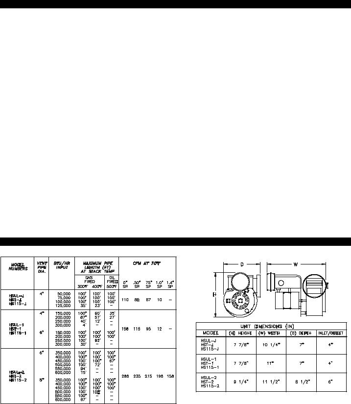
TABLE OF CONTENTS |
|
|
PAGE(S) |
SIZING TABLES AND SPECIFICATIONS ........................................................................................................................................... |
1 |
INSTALLATION RESTRICTIONS.......................................................................................................................................................... |
2 |
CAUTIONS ............................................................................................................................................................................................ |
2 |
GENERAL INFORMATION .................................................................................................................................................................... |
3 |
SAFETY INSPECTION OF EXISTING APPLIANCE INSTALLATION .................................................................................................. |
3 |
INSTALLATION ..................................................................................................................................................................................... |
4 |
VENT SYSTEM TERMINATION............................................................................................................................................ |
4 |
CODE REQUIREMENTS...................................................................................................................................................... |
4 |
POWER VENTER INSTALLATION ...................................................................................................................................................... |
5 |
CODE REQUIREMENTS...................................................................................................................................................... |
5 |
INSTALLATION RESTRICTIONS .................................................................................................................................... |
5 - 6 |
POWER VENTER MOUNTING............................................................................................................................................. |
6 |
DRAFT CONTROL INSTALLATION ON AN INDUCED DRAFT GAS APPLIANCE ............................................................. |
7 |
ELECTRICAL WIRING .......................................................................................................................................................................... |
8 |
WIRING RESTRICTIONS ..................................................................................................................................................... |
8 |
SEQUENCE OF OPERATION ............................................................................................................................................. |
8 |
GAS DIAGRAMS |
|
HSUL SERIES WIRED TO 24V GAS VALVE ...................................................................................................................... |
9 |
HST SERIES WIRED TO 24V GAS VALVE ....................................................................................................................... |
10 |
HSUL SERIES GAS WIRING WITH SINGLE ZONE 24V THERMOSTAT ........................................................................ |
11 |
HST SERIES GAS WIRING WITH SINGLE ZONE 24V THERMOSTAT ........................................................................... |
11 |
HS115 SERIES WIRED TO 115V GAS VALVE OR BURNER MOTOR ............................................................................. |
12 |
HSUL SERIES WIRED TO HONEYWELL SMART VALVE ................................................................................................ |
12 |
OIL DIAGRAMS |
|
HST SERIES OIL WIRING WITH SINGLE ZONE 24V THERMOSTAT.............................................................................. |
11 |
HST SERIES WIRED TO HONEYWELL R8184 SERIES PRIMARY OR EQUIVALENT ........................................... |
12 - 13 |
HST SERIES WIRED TO AN AQUASTAT OR CARLIN CONTROL........................................................................... |
13 - 14 |
DRAFT CHECK AND SAFETY INTERLOCK / COMBUSTION AIR TEST .................................................................................. |
14 - 15 |
HST SERIES POST PURGE TIMER ADJUSTMENT......................................................................................................................... |
15 |
MAINTENANCE .................................................................................................................................................................................. |
15 |
TROUBLESHOOTING GUIDE ...................................................................................................................................................... |
15 - 18 |
HOW TO OBTAIN SERVICE & LIMITED WARRANTY............................................................................................................... |
18 - 19 |
Tjernlund Products welcomes your comments and questions. Call us at 1-800-255-4208, Fax 651-426-9547,
Email us at fanmail@tjfans.com or write to: Customer Service, Tjernlund Products, Inc., 1601 Ninth Street, White Bear Lake, MN 55110-6794.
SPECIFICATIONS
HS-SERIES MODEL SELECTION TABLE
POWER VENTER DIMENSIONS
NOTE: Oil applications must use HST Series which include integral post-purge Relay/Timer
IMPORTANT
Table footage is based on equivalent vent pipe length. To calculate equivalent vent pipe length, add the straight vent pipe plus 10’ for every 90O elbow and 5’ for every 45O elbow.
If venting multiple appliances with one Power Venter, the total combined BTU/hr. input of all appliances must be added together to size the Power Venter.
MODEL |
MOTOR |
CONTROL |
HZ |
RPM |
WATTS |
AMPS |
THERM. |
|
VOLTAGE |
VOLTAGE |
|
|
|
|
PROT. |
HSUL-J |
115 |
2 4 |
6 0 |
3000 |
9 5 |
1.26 |
YES |
|
|
|
|
|
|
|
|
HST-J |
115 |
24/115 |
6 0 |
3000 |
9 5 |
1.26 |
YES |
HS115-J |
115 |
115 |
6 0 |
3000 |
9 5 |
1.26 |
YES |
|
|
|
|
|
|
|
|
HSUL-1 |
115 |
2 4 |
6 0 |
3000 |
9 5 |
1.26 |
YES |
HST-1 |
115 |
24/115 |
6 0 |
3000 |
9 5 |
1.26 |
YES |
|
|
|
|
|
|
|
|
HS115-1 |
115 |
115 |
6 0 |
3000 |
9 5 |
1.26 |
YES |
HSUL-2 |
115 |
2 4 |
6 0 |
3000 |
224 |
1.51 |
YES |
|
|
|
|
|
|
|
|
HST-2 |
115 |
24/115 |
6 0 |
3000 |
224 |
1.51 |
YES |
HS115-2 |
115 |
115 |
6 0 |
3000 |
224 |
1.51 |
YES |
|
|
|
|
|
|
|
|
1
INSTALLATION RESTRICTIONS
1.This device must be installed by a qualified professional installer in accordance with these instructions. If improperly installed, a hazardous condition such as explosion or carbon monoxide poisoning could result.
2.Do not install the Power Venter on incinerators, incinerating toilets, condensing type appliances or solid-fuel burning appliances.
3.The Power Venter shall only be installed on Natural Gas, LP or Oil-fired appliances.
4.Do not install the Power Venter on an appliance with an automatic valve having a manual opener unless the manual opener has been rendered inoperative or the automatic valve has been replaced with a valve not equipped with a manual opener.
5.The Power Venter may only be installed on appliances equipped with a draft hood, draft diverter or barometric draft control.
6.The Power Venter shall not be installed where flue gas temperatures exceed 6000 F. at Power Venter inlet.
FLUE GAS TEMPERATURE VERIFICATION:
A) Consult appliance manufacturer for temperature of gases at the appliance outlet after dilution by draft hood, draft diverter or barometric draft control.
AND
B) Measure temperature of flue gases at the Power Venter inlet at time of installation. Temperature should be measured after appliance and Power Venter have operated for at least 15 minutes, allowing flue gas temperature to stabilize.
Flue gas temperature at Power Venter inlet must not exceed 6000 F.
7.The electrical load controlled through the Fan Proving Switch must not exceed the electrical ratings marked on the Fan Prover.
8.The appliance(s) may only be installed on the suction side of Power Venter.
Improper installation, adjustment, alterations, service or maintenance can cause injury or property damage. Refer to this manual. For assistance or additional information consult a qualified installer, service agency, gas or oil supplier.
CAUTIONS
Failure to install, maintain and/or operate the Power Venter in accordance with manufacturer's instructions may result in conditions which can produce bodily injury and property damage.
The Power Venter must be installed by a qualified installer in accordance with these instructions and all local codes or in their absence in accordance with the latest edition of The National Fuel Gas Code (ANSI Z223.1/NFPA #54), NFPA # 31 Oil Burning Equipment, the latest edition of the National Electrical Code (NFPA#70) and the Occupational Safety and Health Act (OSHA) when applicable. Improper installation can create a hazardous condition such as an explosion, fire, electrical shock or carbon monoxide poisoning resulting in property damage, personal injury or death.
“Qualified Installer” shall mean an individual properly trained and licensed.
Disconnect the power supply when making wiring connections or when working around the fan wheel and motor. Failure to do so can result in electrical shock, personal injury, death or property damage.
1.In order to comply with the UL Listing of the Power Venters the Fan Prover must be wired with the appliance so as to prevent the main burner(s) from firing if the Power Venter malfunctions or the flue is blocked. It is not safe to use the Power Venter on millivolt appliances, such as water heaters which employ a combination gas valve/temperature controller, since the Fan Prover can not be wired as described in this booklet. Millivolt appliances require additional, accessory controls.
2.Plan the vent system so that Code required distances are maintained from plumbing and wiring.
3.The Power Venter motor shaft must be mounted horizontally to ensure proper operation of the Fan Proving Switch and prevent motor bearing wear.
4.Make certain the power supply is adequate for the fan motor requirements. Do not add the Power Venter to a circuit where the total load is unknown.
5.The installer must verify that the BTU/hr. input of the appliance does not exceed the recommended input of the Power Venter. See selection table on page 1 of these instructions for sizing information.
6.Flue gas temperatures must not exceed 6000 F. at the Power Venter inlet. Ambient temperatures surrounding Power Venter must not exceed 1040 F. See “Flue Gas Temperature Verification”, item # 6 above.
7.“Safety Inspection Of a Previously Used Appliance” (Page 3) must be performed before installation on previously used equipment.
2

GENERAL INFORMATION
These units have been factory tested and rated in accordance with AMCA standard 210, Test Code for Air Moving Devices.
Each Power Venter is electrically factory line tested before shipment.
After opening carton, inspect thoroughly for hidden damage. Wheel should rotate freely. If any damage is found notify freight carrier and your distributor immediately and file a concealed damage claim.
IMPORTANT
•The HSUL, HS115 and HST Series Power Venters may be used for gas fired appliances
•The HST Series Power Venters are the only HS units designed for oil and include integral post-purge Relay/Timer.
SAFETY INSPECTION OF A PREVIOUSLY USED GAS APPLIANCE
(Perform prior to Power Venter installation)
The following procedure is intended as a guide to aid in determining that an appliance is properly installed and is in safe condition for continuing use.
The following procedure is based on central furnace and boiler installations and it should be recognized that generalized procedures cannot anticipate all situations. Accordingly, in some cases deviation from this procedure may be necessary to determine safe operation of the equipment.
a.Perform this procedure prior to any attempt at modifications of the appliance or installation of the Power Venter.
b.If it is determined there is a condition which could result in unsafe operation, shut off the appliance and advise the owner of the unsafe condition.
Follow the steps below in making the safety inspection:
1.Conduct a gas leakage test of the appliance piping and control system downstream of the shutoff valve in the supply line to the appliance.
2.Visually inspect the venting system and determine there is no blockage or restriction, leakage, corrosion and other deficiencies which could cause an unsafe condition.
3.Shut off all gas to the appliance(s).
4.Inspect burners and crossovers for blockage and corrosion.
5.Applicable only to furnaces: Inspect heat exchanger for cracks, openings or excessive corrosion. Check both the limit control and fan control for proper operation.
6.Applicable only to boilers: Inspect for evidence of water or combustion product leaks. Determine that the water pumps are in operating condition. Test low water cutoffs, automatic feed controls, pressure and temperature limit controls and relief valves in accordance with the manufacturer's recommendations to determine that they are in operating order.
* Excerpts from the National Fuel Gas Code (ANSI Z223.1/NFPA #54), Appendix H.
SAFETY INSPECTION OF A PREVIOUSLY USED OIL APPLIANCE
(Perform prior to Power Venter installation)
The following procedure is intended as a guide to aid in determining that an appliance is properly installed and is in safe condition for continuing use.
This procedure is based on central furnace and boiler installations and it should be recognized that generalized procedures
cannot anticipate all situations. Accordingly, in some cases deviation from this procedure may be necessary to determine safe operation of the equipment.
a.This procedure should be performed prior to any attempt at modifications of the appliance or installation of the Power Venter.
b.If it is determined there is a condition which could result in unsafe operation, the appliance should be shut off and the owner advised of the unsafe condition.
The following steps should be followed in making the safety inspection:
1.Visually inspect the venting system and determine there is no blockage or restriction, leakage, corrosion or other deficiencies which could cause an unsafe condition.
2.Inspect burner and primary control for proper operation.
3.Applicable only to furnaces: Inspect heat exchanger for cracks, openings or excessive corrosion. Check both the limit control and fan control for proper operation.
4.Applicable only to boilers: Inspect for evidence of water or combustion product leaks. Determine that the water pumps are in operating condition. Test low water cutoffs, automatic feed controls, pressure and temperature limit controls and relief valves in accordance with the manufacturer's recommendations to determine that they are in operating order.
* Excerpts from the National Fuel Gas Code (ANSI Z223.1/NFPA #54), Appendix H.
3

INSTALLATION
|
VENT SYSTEM TERMINATION |
|
Before installing Power Venter determine location of vent system termination. |
|
|
|
TOOLS REQUIRED |
|
• Saber Saw or Cement Drill |
• Drill |
• 1/8” and 1/4” Drill Bits |
• Wood or Masonry Chisel |
• Blade Screwdriver or 1/4” Nut Driver |
• Wire Cutter/Stripper |
For oil installations do not terminate HS-Series Power Venters on vinyl siding because temperatures can easily exceed 1500F. The SideShot® is the only Tjernlund Power Venter recommended for termination on vinyl siding when using oil.
NOTE: Termination of a Side Wall Vent System with a device other than the Tjernlund VH1 Series Vent Hood could affect system performance and result in a possible safety hazard. Consult Vent Hood instructions for complete installation details.
If possible, locate the Vent Hood on a wall that does not face the direction of prevailing winds. This will diminish the possibility of appliance interruption during periods of extreme winds and prevent oil odors caused by backdrafts.
If possible, locate the Vent Hood no closer than 3 feet from an inside corner of an L-shaped structure.
CODE REQUIREMENTS
Terminate the vent system so that proper minimum clearances are maintained as cited in the latest edition of the National Fuel Gas Code (NFPA # 54) and the latest edition of NFPA #211, or as follows:
•Not be less than 7 feet above grade when located adjacent to public walk ways.
•At least 3 feet above any forced air inlet located within 10 feet.
•At least 4 feet below, 4 feet horizontally from or 1 foot above any door, window or gravity air inlet into any building.
•At least 12 inches above grade.
•So that the flue gases are not directed so as to jeopardize people, overheat combustible structures or enter buildings, and
•Not less than 2 feet from an adjacent building.
4

POWER VENTER INSTALLATION
VERIFY POWER VENTER MODEL SELECTION USING TABLES ON PAGE 1.
CODE REQUIREMENTS
The Power Venter installation must be done in accordance with the following requirements of the latest Edition of the National Fuel Gas Code (NFPA #54):
•All portions of the vent system under positive pressure during operation (on the outlet side of Power Venter) shall be designed and installed so as to prevent leakage of flue or vent gases into the building.
•All appliances must enter the vent system on the inlet side of the Power Venter.
•Provision shall be made to interlock the appliance(s) to prevent the flow of gas to the main burners when the draft system is not performing so as to satisfy the operating requirements of the equipment for safe performance. See “Electrical Wiring” section of this manual for details.
INSTALLATION RESTRICTIONS
DIAGRAM A
1. Power Venter must be installed as close as possible to the termination of the vent system to obtain optimal appliance efficiency and to prevent flue gas leakage, (See Diagram A).
2. The Power Venter may be mounted in any position as long as the shaft of the motor remains horizontal, to prevent motor bearing wear and to ensure proper Fan Proving Switch operation, (See Diagram B).
DIAGRAM B
3. The Power Venter housing is single wall. A 6” clearance to
combustibles must be maintained for gas and 18” clearance for oil DIAGRAM C applications, (See Diagram C). If the appliance nameplate specifies a
vent connector clearance greater than 6 inches, the greater clearance must be used. Refer to NFPA # 31 for Oil Burning Equipment.
NOTE: Clearance to combustibles may be reduced. Please refer to
Clearance Table VI in NFPA #54 and your local code authority.
4. Vent pipe transitions, where necessary, must be gradually tapered, (See Diagram D).
DIAGRAM D
5
 Loading...