


REV. A 7/00
TJERNLUND PRODUCTS, INC. |
1601 Ninth Street • White Bear Lake, MN 55110-6794 |
PHONE (800) 255-4208 • (651) 426-2993 • FAX (651) 426-9547 |
Visit our web site • www.tjernlund.com |
AUTO-DRAFT® INDUCER
INSTALLATION INSTRUCTIONS
|
MODELS |
|||||||||||||||||
DJ-3 |
|
|
|
|
|
|
|
|
|
|
|
|
|
|
|
|
|
IL |
D-3 |
|
|
|
|
|
|
|
|
|
|
|
|
|
|
|
|
|
XL |
I |
|
|
|
|
|
|
|
|
|
|
|
|
|
|
|
|
|
HD |
|
|
|
|
|
|
|
|
|
|
|
|
|
|
|
|
|
|
|
|
|
|
|
|
|
|
|
|
|
|
|
|
|
|
|
|
|
|
|
|
|
|
|
|
|
|
|
|
|
|
|
|
|
|
|
|
|
|
|
|
|
|
|
|
|
|
|
|
|
|
|
|
|
|
|
|
|
|
|
|
|
|
|
|
|
|
|
|
|
|
|
|
|
|
|
|
|
|
|
|
|
|
|
|
|
|
|
|
|
|
|
|
|
|
|
|
|
|
|
|
|
|
|
|
|
|
|
|
|
|
|
|
|
|
|
|
|
|
|
|
|
|
|
|
|
|
|
|
|
|
|
|
|
|
|
|
|
|
|
|
|
|
|
|
|
|
|
|
|
|
|
OWNER INSTRUCTIONS, DO NOT DESTROY
 Recognize this symbol as an indication of important Safety Information!
NOTE: FLUE GAS TEMPERATURES MUST NOT EXCEED
575oF AT DRAFT INDUCER INLET. DRAFT INDUCERS MUST NOT BE USED FOR SIDEWALL VENTING APPLICATIONS.
THESE INSTRUCTIONS ARE INTENDED AS AN AID TO QUALIFIED, LICENSED SERVICE PERSONNEL FOR PROPER INSTALLATION, ADJUSTMENT AND OPERATION OF THIS UNIT. READ THESE INSTRUCTIONS THOROUGHLY BEFORE ATTEMPTING INSTALLATION OR OPERATION. FAILURE TO FOLLOW THESE INSTRUCTIONS MAY RESULT IN IMPROPER INSTALLATION, ADJUSTMENT, SERVICE OR MAINTENANCE POSSIBLY RESULTING IN FIRE, ELECTRICAL SHOCK, CARBON MONOXIDE POISONING, EXPLOSION, PERSONAL INJURY OR PROPERTY DAMAGE.
DO NOT DESTROY. PLEASE READ CAREFULLY AND
KEEP IN A SAFE PLACE FOR FUTURE REFERENCE.
Copyright © 2000, Tjernlund Products, Inc. All rights reserved. |
P/N 8504003 |

TABLE OF CONTENTS |
|
|
PAGE(S) |
DESCRIPTION ............................................................................................................................................................... |
1 |
SPECIFICATIONS .......................................................................................................................................................... |
1 |
CAUTIONS ..................................................................................................................................................................... |
1 |
INSTALLATION RESTRICTIONS................................................................................................................................... |
2 |
DRAFT INDUCER SELECTION TABLE ........................................................................................................................ |
2 |
PS1505 FAN PROVER SAFETY INTERLOCK INSTALLATION ................................................................................... |
3 |
INSTALLATION ......................................................................................................................................................... |
3 - 5 |
ELECTRICAL WIRING ............................................................................................................................................. |
5 - 9 |
TYPICAL GAS DIAGRAMS........................................................................................................................ |
5 - 8 |
TYPICAL OIL DIAGRAMS.......................................................................................................................... |
8 - 9 |
OPERATION CIRCUIT CHECK.............................................................................................................................. |
9 - 10 |
P/N 950-1067 POST PURGE RELAY/TIMER ADJUSTMENT ................................................................................... |
10 |
COMBUSTION AIR & SAFETY INTERLOCK TEST..................................................................................................... |
10 |
DRAFT CONTROL........................................................................................................................................................ |
10 |
MAINTENANCE .................................................................................................................................................... |
10 -11 |
HOW TO OBTAIN SERVICE & LIMITED WARRANTY................................................................................................ |
11 |
REPLACEMENT PARTS.............................................................................................................................................. |
11 |
Tjernlund Products welcomes your comments and questions. Call us at (651) 426-2993, (800) 255-4208, Fax (651) 426-9547, email us at fanmail@tjfans.com or write to: Customer Service, Tjernlund Products, Inc., 1601 Ninth Street, White Bear Lake, MN 55110-6794.
DESCRIPTION
TJERNLUND AUTO-DRAFT® Inducers assure positive draft when restricted boilers and furnaces, poor chimneys or slight negative pressures in buildings prevent proper exhaust of combustion gas. The venturi action of Tjernlund Auto-Draft Inducers starts air moving smoothly. These units are quick and easy to install and completely automatic in operation. Tjernlund’s unique design and durable construction makes them trouble-free and reduces maintenance to a minimum. The Vari-Draft Control permits adjustments to the individual job requirement.
SPECIFICATIONS
“H” - OVERALL HEIGHT “D” - OVERALL DEPTH “W” - OVERALL WIDTH “X” - PIPE SLOT WIDTH “Y” - PIPE SLOT HEIGHT
CAUTIONS
Disconnect the power supply when making wiring connections or when working around the fan wheel and motor. Failure to do so can result in electrical shock, personal injury, death or property damage.
1.All wiring must comply with applicable codes and ordinances.
2.When wiring is completed, check all components by running system through its entire heating cycle. See “Operation Circuit Check” on page 9 and “Safety Interlock / Combustion Air Test” on page 10.
3.Check vent pipe system for leakage. All vent system leaks must be sealed prior to the installation of the Draft Inducer.
4.Plan the vent system so that Code required distances are maintained from plumbing and wiring.
5.Make certain the power supply is adequate for the Draft Inducer motor requirements. Do not add the Draft Inducer to a circuit where the total load is unknown. For Draft Inducer motor amperage see “Draft Inducer Selection Table” on page 2.
6.The Draft Inducer shall not be installed where flue gas temperatures exceed 575OF at the Draft Inducer Inlet. Ambient temperatures must not exceed 104 degrees F. Item #4 under “Installation Restrictions” describes how to measure flue gas temperatures.
7.A safety inspection of an existing appliance must be performed before installation of the Draft Inducer as outlined in ANSI Z223.1/NFPA #54, Appendix H.
1

INSTALLATION RESTRICTIONS
Failure to install, maintain and/or operate the Draft Inducer in accordance with manufacturer's instructions may result in conditions which can produce bodily injury and property damage.
The Draft Inducer must be installed by a qualified installer in accordance with these instructions and all local codes or in their absence in accordance with the latest editions of The National Fuel Gas Code (NFPA #54), Installation of Fuel Burning Equipment (NFPA 31), Chimneys, Fireplaces, Vents, and Solid Fuel Burning Appliances (NFPA 211), The National Electrical Code (NFPA#70) and the Occupational Safety and Health Act (OSHA) when applicable. Improper installation can create a hazardous condition such as an explosion, fire, electrical shock or carbon monoxide poisoning resulting in property damage, personal injury or death.
1.The Draft Inducer shall not be used on condensing heating equipment.
2.Oil burning installations and gas-fired units without a draft hood / diverter should include a barometric draft regulator.
3.The Draft Inducer motor shaft must be mounted horizontally to prevent motor bearing wear.
4.The Draft Inducer shall not be installed where flue gas temperatures exceed 575OF at the Draft Inducer Inlet. Ambient room temperatures must not exceed 104 degrees F.
Flue gas temperature verification:
A)Consult appliance manufacturer for temperature of gases at the appliance outlet after dilution by draft hood, draft diverter or barometric draft control.
AND
B)Measure temperature of flue gases at the Draft Inducer inlet at time of installation. Temperature should be measured after appliance and Draft Inducer have operated for at least 10 minutes, allowing flue gas temperature to stabilize.
DRAFT INDUCER SELECTION TABLE
1.Inputs shown are believed to be maximum capacities for inducers when mounted on pipe sizes shown for ordinary jobs where a moderate amount of mechanical induced draft is required.
2.Consideration is given to typically higher static pressure requirements for larger installations, for the type of fuel burned and for the type of draft control installed.
3.Where pressure requirements are unknown or believed to be unusually severe, ask for complete performance curves or consult factory.
4.All ratings have been developed in our testing and research department and have been approved by a nationally known independent testing laboratory. Certification is available upon request.
5.Heating capacities shown are for 1000 BTU per cubic foot natural gas and for 139,000 BTU per gallon No. 2 fuel oil.
Consult factory for capacities with other fuels. Heating capacities are based on typical combustion efficiencies and allow for approximately 5 percent ambient air drawn into inducer to
cool motor and drives.
6.Draft Inducers should be installed in single wall vent pipe in order to insure proper performance.
PIPE |
GAS FIRING |
GAS FIRING |
OIL FIRING |
|
|||
|
WITH |
|
WITH |
ELECTRICAL |
|||
SIZE |
|
WITH |
BAR. DRAFT |
BAR. DRAFT |
DATA |
||
IN. |
DRAFT HOOD |
CONTROL |
CONTROL |
|
|||
MODEL |
|
|
|
|
|
|
|
|
HEATER |
HEATER |
HEATER |
|
|||
|
BTU |
FLUE GAS |
BTU |
FLUE GAS |
BTU |
FLUE GAS |
|
|
INPUT |
|
INPUT |
|
INPUT |
|
|
|
|
S.P. CFM |
|
S.P. CFM |
|
S.P. CFM |
|
DJ-3 |
|
|
|
|
|
|
|
D-3 |
|
|
|
|
|
|
|
I |
|
|
|
|
|
|
|
IL |
|
|
|
|
|
|
|
XL |
|
|
|
|
|
|
|
HD |
|
|
|
|
|
|
|
|
|
2 |
|
|
|
|
|
MODEL PS1505 FAN PROVING SWITCH SAFETY INTERLOCK
The Model PS1505 Fan Proving Switch works on all Tjernlund Draft Inducers to assure adequate draft is present before burner is allowed to fire. The PS1505 complies with burner safety interlock provisions of National Mechanical Codes.
PURPOSE
The PS1505 Fan Prover has been designed to monitor the pressure within the fan housing only. A motor or wheel failure will decrease housing pressure and deactivate the pressure switch thus preventing combustion.
The PS1505 Fan Prover is not a safety control designed to ensure proper draft or to indicate chimney failure. It is the responsibility of the end user to properly maintain the combustion equipment and its chimney or vent. Yearly maintenance and inspection should be conducted by qualified service personnel. Failure to follow such maintenance and inspection procedures may result in generation of toxic carbon monoxide gas.
LOCATION
The PS1505 Fan Prover can be mounted on any vertical surface within five (5) feet of the draft inducer. It must not be mounted on the inducer or any other surface with a temperature in excess of 190o F. Similarly, the temperature of the surrounding air must be less than 190o F.
RATING
15 Amps non-inductive to 277 Volts AC.
INSTALLATION
CODE REQUIREMENTS
The Draft Inducer must be installed by a qualified installer in accordance with these instructions and all local codes or in their absence in accordance with the latest editions of The National Fuel Gas Code (NFPA #54), Installation of Fuel Burning Equipment (NFPA 31), Chimneys, Fireplaces, Vents, and Solid Fuel Burning Appliances (NFPA 211), The National Electrical Code (NFPA#70) and the Occupational Safety and Health Act (OSHA) when applicable.
•All appliances must enter the vent system on the inlet side of the Draft Inducer.
•Provision shall be made to interlock the appliance(s) to prevent the flow of gas to the main burners when the draft system is not performing so as to satisfy the operating requirements of the equipment for safe performance. See “Electrical Wiring” on page 5.
INSTALLER NOTES
1.Verify Draft Inducer selection using burner specifications and Draft Inducer Selection Table on page 2.
2.Make certain that the electrical requirements of the Draft Inducer shown on page 2 are fulfilled by the available power supply.
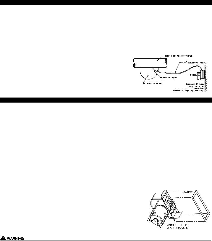
HIGH TEMPERATURE GASKET MATERIAL MOUNTING (MODELS I, IL, XL ONLY)
1. Peel tape backing off 6 inches on one end.
2. Apply peeled end to the housing flange at a corner of the unit.
3. Press thumb along the top side and peel backing as tape is applied to flange. 4. Insure a tight fit where gasket ends meet.
MOUNTING
The Draft Inducer must not be used in sidewall venting applications. Sidewall venting requires the use of a Tjernlund Sidewall Power Venter.
1.The Draft Inducer may be mounted on vertical, horizontal or inclined smokepipe. If used on a horizontal smokepipe, mount inducer on bottom of pipe, not on top, to avoid creating a heat trap in inducer.
2.Cut rectangular slot in pipe and fasten in place with mounting bands provided. NOTE: The models DJ-3 & D-3 do not require bands, use mounting screws provided.
3.Select a position between draft hood, draft diverter or barometric damper and chimney, locating the inducer as near the chimney as possible. The motor shaft must be level and horizontal to avoid excessive wear of bearings.
3
 Loading...