


Owner’s Manual
Notice d’utilisation Manual del Propietario
Do not use this equipment before reading this manual!
CAPSpray 115
HVLP Spray System
Model |
0524034 |
Model |
0524099 |
Register your product online at:
www.titantool.com
Serial Number* _ _ _ _ _ _ _ _ _ _
NOTE: This manual contains important warnings and instructions. Please read and retain for reference.
0814 • © Titan Tool Inc. All Rights Reserved. Form No. 0524858G
* See page 5 for location

Important Safety Information
|
Read all safety information before operating the |
|
|
|
replace the hose if any of these conditions exist. Never repair a hose. |
|||||||
|
|
|
|
|||||||||
|
|
|
|
Replace it with an identical replacement hose. |
||||||||
|
equipment. Save these instructions. |
|
|
• Do not spray outdoors on windy days. |
||||||||
|
|
|
|
|
|
|
|
|||||
|
|
|
|
|
|
|
|
• Wear clothing to keep paint off skin and hair. |
||||
|
Indicates a hazardous situation which, if not avoided, |
|
||||||||||
|
|
|
• Never aim the spray gun at any part of the body. |
|||||||||
|
could result in death or serious injury. |
|
|
|||||||||
|
|
|
|
|
|
|
|
|||||
|
To reduce the risks of fire or explosion, electrical shock |
|
|
|
|
|
|
|
||||
|
|
|
|
|
|
HAZARD: |
EXPLOSION HAZARD DUE TO |
|||||
|
and the injury to persons, read and understand all |
|
|
|
|
|
||||||
|
|
|
|
|
|
|
INCOMPATIBLE MATERIALS |
|||||
|
instructions included in this manual. Be familiar with the |
|
|
|
|
|
|
|||||
|
|
|
|
|
|
Will cause property damage or severe injury. |
||||||
|
controls and proper usage of the equipment. |
|
|
|
|
|
||||||
|
|
|
|
|
|
|
|
|
|
|
|
|
Grounding Instructions |
|
PREVENTION: |
|
|||||||||
|
|
• Do not use materials containing bleach or chlorine. |
||||||||||
This product must be grounded. In the event of an electrical short circuit, |
|
|
• Do not use halogenated hydrocarbon solvents such as bleach, |
|||||||||
grounding reduces the risk of electric shock by providing an escape wire for |
|
|
||||||||||
|
|
|
mildewcide, methylene chloride and 1,1,1 - trichloroethane. They are |
|||||||||
the electric current. This product is equipped with a cord having a grounding |
|
|
|
|||||||||
|
|
|
not compatible with aluminum. |
|||||||||
wire with an appropriate grounding plug. The plug must be plugged into |
|
|
|
|||||||||
|
|
• Contact your coating supplier about the compatibility of material with |
||||||||||
an outlet that is properly installed and grounded in accordance with all local |
|
|
||||||||||
codes and ordinances. |
|
|
|
aluminum. |
|
|||||||
|
warning - Improper installation of the grounding plug |
|
|
|
|
|
|
|
||||
|
|
|
|
|
|
HAZARD: |
EXPLOSION OR FIRE |
|||||
|
can result in a risk of electric shock. |
|
|
|
|
|
||||||
If repair or replacement of the cord or plug is necessary, do not connect the |
|
|
|
|
|
Solvent and paint fumes can explode or ignite. Property |
||||||
|
|
|
|
|
damage and/or severe injury can occur. |
|||||||
green grounding wire to either flat blade terminal. The wire with insulation |
|
|
|
|
|
|||||||
having a green outer surface with or without yellow stripes is the grounding |
|
|
|
|
|
|
|
|||||
wire and must be connected to the grounding pin. |
|
PREVENTION: |
|
|||||||||
Check with a qualified electrician or serviceman if the grounding instructions |
|
|
||||||||||
|
|
• Exhaust and fresh air introduction must be provided to keep the air |
||||||||||
are not completely understood, or if you are in doubt as to whether the |
|
|
||||||||||
|
|
|
within the spray area free from accumulation of flammable vapors. |
|||||||||
product is properly grounded. Do not modify the plug provided. If the plug |
|
|
|
|||||||||
will not fit the outlet, have the proper outlet installed by a qualified electrician. |
|
|
• |
Turbine contains sparking parts. Turbine must be placed in a well |
||||||||
|
|
Grounded Outlet |
|
|
|
ventilated area at maximum distance from the spray area. |
||||||
|
|
|
|
• Avoid all ignition sources such as static electricity, open flames, |
||||||||
|
|
|
|
|
|
|
|
|
pilot lights, hot objects, cigarettes, and sparks from connecting and |
|||
|
|
|
|
|
|
|
|
|
disconnecting power cords and working light switches. |
|||
|
|
Grounding Pin |
|
|
• Use extreme caution when using materials with a flashpoint below |
|||||||
|
|
|
|
|
100° F (38°C). A fluid’s flashpoint is the temperature at which vapors |
|||||||
|
|
|
|
|
|
|
|
|
||||
|
|
|
Cover for grounded outlet box |
|
|
|
from the fluid could ignite if exposed to a flame or spark. |
|||||
|
|
|
|
|
• Fire extinguishing equipment must be present and in working order. |
|||||||
IMPORTANT: Use only a 3-wire extension cord that has a 3-blade |
|
|
||||||||||
|
|
• The power cord must be connected to a grounded circuit. |
||||||||||
grounding plug and a 3-slot receptacle that will accept the plug on the |
|
|
||||||||||
|
|
• Follow the material and solvent manufacturer’s safety precautions and |
||||||||||
product. Make sure the extension cord is in good condition. When |
|
|
||||||||||
using an extension cord, be sure to use one heavy enough to carry the |
|
|
|
warnings. |
|
|||||||
current the product will draw. An undersized cord will cause a drop |
|
|
|
|
|
|
|
|||||
in line voltage resulting in loss of power and overheating. A 12 gauge |
|
|
|
|
|
HAZARD: |
HAZARDOUS VAPORS |
|||||
cord is recommended. If an extension cord is to be used outdoors, it |
|
|
|
|
|
|||||||
must be marked with the suffix W-A after the cord type designation. For |
|
|
|
|
|
Paints, solvents, insecticides, and other materials can |
||||||
example, a designation of SJTW-A would indicate that the cord would be |
|
|
|
|
|
|||||||
|
|
|
|
|
be harmful if inhaled or come in contact with the body. |
|||||||
appropriate for outdoor use. |
|
|
|
|
|
|||||||
|
|
|
|
|
Vapors can cause severe nausea, fainting, or poisoning. |
|||||||
|
|
|
|
|
|
|
|
|
|
|
||
|
|
|
|
|
|
|
|
|
|
|||
|
NOTE: More than 100 feet of extension cord is not recommended. |
|
|
|
|
|
|
|
|
|||
|
|
|
PREVENTION: |
|
||||||||
|
|
Use more hose, not more extension cord. Shorter extension |
|
|
|
|||||||
|
|
|
|
|
• |
Use a respirator or mask if vapors can be inhaled. Read all instructions |
||||||
|
|
cords will assure maximum electrical power for proper |
|
|
|
|||||||
|
|
operation. |
|
|
|
|
supplied with the mask to be sure it will provide the necessary |
|||||
|
|
|
|
|
|
|
|
|
protection. |
|
||
|
|
|
|
|
|
|
|
|
|
|||
|
|
|
|
|
|
|
|
• |
Wear protective eyewear. |
|||
|
|
HAZARD: GENERAL |
|
|
• Wear protective clothing as required by coating manufacturer. |
|||||||
|
|
|
|
|
|
|
|
|
||||
|
|
Can cause severe injury or property damage. |
|
|
|
|
|
|
|
|||
|
|
|
|
|
|
|
HAZARD: |
Skin burn injury |
||||
|
|
|
|
|
|
|
|
|
|
|
||
PREVENTION: |
|
|
|
|||||||||
|
|
|
|
|
Heated parts can cause severe skin burn injury. |
|||||||
|
• Read all instructions and safety precautions before operating any |
|
|
|
|
|
|
|
||||
|
equipment. |
|
PREVENTION: |
|
||||||||
|
• Follow all appropriate local, state, and national codes governing |
|
|
• Quick disconnect fittings on the hose and spray gun become hot |
||||||||
|
ventilation, fire prevention, and operation. |
|
|
|
during use. Avoid skin contact with quick disconnect fittings |
|||||||
|
• The United States Government Safety Standards have been adopted |
|
|
|
when they are hot. Allow quick disconnect fittings to cool before |
|||||||
|
under the Occupational Safety and Health Act (OSHA). These |
|
|
|
disconnecting the spray gun from the hose. |
|||||||
|
standards, particularly Part 1910 of the General Standards and Part |
|
Service |
|
||||||||
|
1926 of the Construction Standard should be consulted. |
|
|
|||||||||
|
• Use only manufacturer authorized parts. User assumes all risks |
|
Should your spray system need service during the warranty period, |
|||||||||
|
and liabilities when using parts that do not meet the minimum |
|
||||||||||
|
|
return your unit and the proof of purchase to the distributor where it was |
||||||||||
|
specifications and safety devices of the manufacturer. |
|
||||||||||
|
|
purchased. At our option, the unit will be repaired or replaced. In a continued |
||||||||||
|
• Before each use, check all hoses for cuts, leaks, abrasion or bulging |
|
commitment to improve quality, we reserve the right to make component or |
|||||||||
|
of cover. Check for damage or movement of couplings. Immediately |
|
design changes when necessary. |
|||||||||
|
|
|
|
|
|
|
|
|
|
|
|
|
|
|
|
English |
|
|
2 |
|
|
|
|
© Titan Tool Inc. All rights reserved. |
|
|
|
|
|
|
|
|
|
|
|
|
|
|
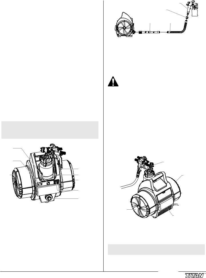
Table of Contents |
|
Safety................................................................................................ |
2 |
Grounding Instructions.................................................................................. |
2 |
Service............................................................................................... |
3 |
Introduction...................................................................................... |
3 |
Using an HVLP Spray System.......................................................... |
3 |
Setup..................................................................................................................... |
3 |
Dual Filtration System.................................................................................... |
3 |
Maintenance..................................................................................... |
4 |
Cleaning/Replacing Filters............................................................................ |
4 |
Cleaning the Air Hoses................................................................................... |
4 |
Troubleshooting.............................................................................. |
5 |
Product Registration........................................................................ |
5 |
Français............................................................................................. |
6 |
Español............................................................................................ |
10 |
Parts List..................................................................................... |
14-17 |
Wiring Diagram.............................................................................. |
18 |
Warranty......................................................................................... |
20 |
Introduction
This High Volume/Low Pressure (HVLP) spray system is designed for applying coatings to surfaces that can be sprayed faster than brushing or rolling and are too small for traditional airless sprayers. Components of this system include a power switch, a power cord, a
filter warning light, a circuit breaker switch, a dual filtration system, a cup holder, an air hose, and an air outlet.
The power switch comes with two speed settings. Low speed is generally used for light-bodied materials. High speed is ideal for thicker materials.
The turbine is also equipped with a tool box. It is located on the reverse side of the turbine and can be used to store projector sets or any other small spare parts.
NOTE: Some of the graphics in this manual may not exactly match your turbine and spray gun. All information and instructions given in this manual applies to all models except where noted.
Circuit |
|
breaker |
|
switch |
|
Filter |
|
warning |
|
light |
Air inlet |
|
|
Filter |
Cup holder |
|
Filter |
|
(in end of |
|
filter can) |
|
Power switch / |
|
Speed selector |
|
Air outlet |
*Air hose not pictured
With this HVLP spray system, you can achieve the highest quality professional finish possible with little or no preparation or setup time. Please review all the information contained in this manual before operating the system.
Using an HVLP Spray System
Refer to the following information to operate and understand your HVLP spray system.
Your system may include a short air (“whip”) hose. The short hose should be connected to the longer hose or a remote spraying system (sold separately) and NOT directly to the turbine. See your spray gun instruction manual for complete instructions.
|
|
Spray gun |
Turbine |
Coupling |
|
|
Air hose |
Whip hose |
important: Do not attach the short air whip hose directly to the turbine, as the hose will become damaged.
Setup
Use the following procedure to set up your HVLP spray system for operation.
1.Plug the turbine power cord into a grounded, 3-slot receptacle.
Keep the turbine at the maximum possible distance from the spray area to safeguard against explosion or fire that may be caused by sparking electrical parts.
2.Prepare your spray gun for operation. Refer to your spray gun manual for material preparation, setup, and spraying information.
3.Attach the air hose to the air outlet on the turbine.
4.Attach the air hose to the air inlet on your spray gun.
5.Turn on the turbine and begin spraying.
Dual Filtration System
The turbine has two different air filters— one for atomizing air and one for cooling air. The atomizing air filter is a two-stage, fine mesh filter designed to trap particles that may damage your finish. The atomizing air is discharged through the nozzle of the spray gun where it atomizes the coating material. The cooling air filter is a coarse mesh filter designed to allow the proper amount of air flow through the turbine for cooling purposes. Cooling air is exhausted through the cooling air discharge on the front of the turbine.
Atomizing air


 discharge rear of turbine

Atomizing air intake
Cooling air |
|
intake |
Cooling air discharge |
|
Filter Warning System
The filter warning system on your turbine consists of a red filter warning light on the front control panel and an air flow switch inside the turbine. When the air flow switch does not detect the appropriate amount of air flowing through the turbine, the filter warning light will come on to indicate that it is time to clean or change the filters.
NOTE: The filter warning system does not shut down the turbine.
IMPORTANT: Clean filters regularly. Clogged filters can cause excessive heat and possibly damage the turbine.
© Titan Tool Inc. All rights reserved. |
3 |
English |
|
|
|
Maintenance
Use the following procedures to keep your HVLP spray system running properly.
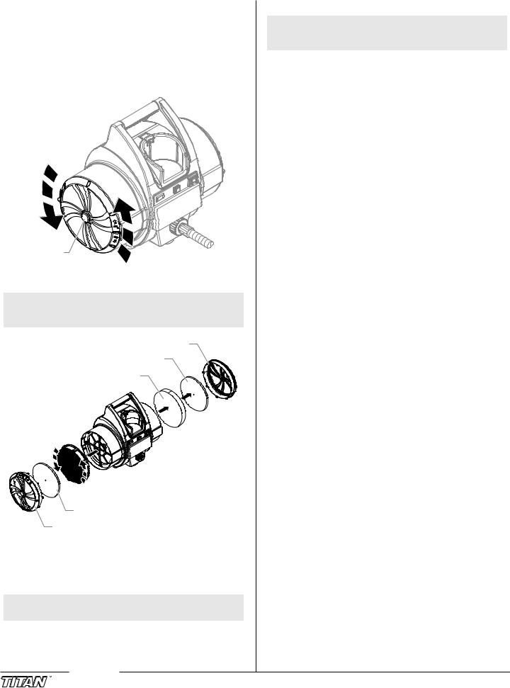
Cleaning / Replacing the Filters
important: Make sure the turbine is unplugged before changing the filters.
1.Remove the filter covers on each side of the turbine by turning them counterclockwise.
Filter cover
2.Remove each filter set (pre-filter and filter) from the filter housing on each side of the turbine.
NOTE: The white pleated filter is removed from the turbine in the same manner as the filter cover. Turn counterclockwise to unlock and remove.
Filter cover
Pre-filter
Filter
 White pleated filter
Pre-filter
Filter cover
3.Clean the filters. Either tap the filters to knock out the contaminants or use pressurized air to blow out the contaminants. For material that is not blown or knocked loose easily, soak the filters in soapy water or mineral spirits. Allow the filters to dry completely before placing them back in the turbine.
NOTE: Do not use highly flammable solvents, such as lacquer thinner, to clean the filters.
IMPORTANT: Do not soak paper pleated filter in solvents. Only tap the filter or use compressed air directed at the inside (the clean side).
4.Insert each filter back into its corresponding filter can.
NOTE: Make sure the white pleated filter is fitted securely to the spokes of the filter can. Turn clockwise to secure in place.
5.Replace the filter covers on each side of the turbine by turning them clockwise.
After several cleanings, it may become necessary to replace the filters. Refer to the parts list near the end of this manual for the filter replacement kit part number.
Cleaning the Air Hoses
1.Periodically wipe the outer surface of the air hose with a damp cloth to keep clean.
IMPORTANT: DO NOT submerge into or flush the air hose with water or any chemical.
IMPORTANT: DO NOT use methylethylketon (MEK), naphtha, mineral spirits, paint thinner, xylol/xylene, or toluel/toluene to clean the air hose. Exposure over time could cause damage to the hose.
IMPORTANT: Store indoors with the cord wrapped around the handle.
English |
4 |
© Titan Tool Inc. All rights reserved. |
|
|
|

Troubleshooting
Problem |
Cause |
|
|
Solution |
|||||||
A. |
Restricted air flow or no air flow |
1. |
Air flow adjustment knob on the spray gun is |
1. |
Adjust the air flow adjustment knob |
||||||
|
|
|
|
|
|
turned off |
|
|
|
|
|
|
|
|
|
2. |
Air filters are clogged |
2. |
Clean or replace the filters |
||||
|
|
|
|
|
|
|
|
|
|
|
|
B. |
Filter warning light is on |
1. |
Air filters are clogged |
1. |
Clean or replace the filters |
||||||
|
|
|
|
|
|
|
|
|
|
|
|
C. |
The turbine has no power |
1. |
No power at the power supply |
1. |
Check the power supply |
||||||
|
|
|
|
2. |
Circuit breaker has been tripped. |
2. |
Reset the breaker. If problem persists, have turbine |
||||
|
|
|
|
|
|
|
|
|
|
inspected at an authorized Titan service center. |
|
|
|
|
|
3. |
Worn turbine brushes |
3. |
Have the brushes replaced at an authorized Titan service |
||||
|
|
|
|
|
|
|
|
|
|
center |
|
|
|
|
|
|
|
|
|
|
|
|
|
D. |
Excessive arcing/sparking in the |
1. |
Worn turbine brushes |
1. |
Have the brushes replaced at an authorized Titan service |
||||||
|
|
turbine |
|
|
|
|
|
|
center |
||
|
|
|
|
2. |
Damaged commutator |
2. |
Replace the turbine (contact a Titan service technician) |
||||
IMPORTANT:
•The turbine motor can be damaged if not serviced properly.
Have the brushes (Kit P/N 0277243) checked for wear by an authorized service center every 400 hours.
•Clean filters regularly. When the filter warning light comes on, it is time to clean the filters. Clogged filters cam cause excessive heat and possibly damage the unit.
•For additional troubleshooting information, see the manual that came with your gun.
Specifications
Air pressure |
11.5 psi |
Power |
120VAC, 60 Hz, 15.0 A |
Turbine weight |
24 lbs |
Main hose length |
30 ft |
Whip hose length |
5 ft |
Spray gun included |
Maxum II or Maxum Elite |
|
|
Product Registration
Register your product at www.titantool.com
Serial Number Location
xxxxxxx
Titan 30-Day Satisfaction Guarantee
If, within a 30-day period from the date of purchase, you are not totally satisfied with a Titan unit, you may return it for full credit toward another Titan product of equal or greater value.
© Titan Tool Inc. All rights reserved. |
5 |
English |
|
|
|

Consignes de sécurite important
|
Lire toutes ces consignes avant d’utiliser l’appareil. |
raccords ne soient pas endommagés. Si le flexible a subi l’un des |
||||||
|
dommages précités, remplacez-le immédiatement. Ne jamais réparer |
|||||||
|
Garder ces consignes. |
un flexible d’alimentation. Le remplacer avec un flexible identique de |
||||||
|
|
|
|
|
remplacement. |
|
||
|
|
|
|
|
|
|||
|
Indique une situation à risque, laquelle, si elle n’est pas évitée, |
• Ne jamais pulvériser lorsqu’il vente. |
||||||
|
• Porter des vêtements pour protéger la peau et les cheveux contre tout |
|||||||
|
peut entraîner des blessures graves, voire la mort. |
|||||||
|
Pour réduire les risques d’incendie ou d’explosion, de choc |
contact avec la peinture. |
||||||
|
• On ne doit jamais orienter le pistolet vers une partie du corps. |
|||||||
|
électrique et de blessure, vous devez lire et comprendre les |
|||||||
|
directives figurant dans ce manuel. Familiarisez-vous avec les |
|
|
|
||||
|
|
Danger : |
RISQUES D’EXPLOSION PAR INCOMPATIBILITÉ |
|||||
|
commandes et l’utilisation adéquate de l’équipement. |
|
||||||
Instructions de mise à la terre |
|
|
DES MATÉRIAUX |
|||||
|
Peuvent être à l’origine de corporels sérieux ou dommages matériels. |
|||||||
|
|
|
|
|
|
|||
Cet appareil doit être mis à la terre. La mise à la terre réduit les risques |
|
|
|
|||||
Prévention : |
|
|||||||
d’électrocution lors d’un court-circuit en permettant au courant de s’écouler |
• Ne pas utiliser de matériaux contenant des agents de blanchiment ou |
|||||||
par le fil de mise à la terre. Cet appareil est muni d’un cordon électrique avec |
||||||||
du chlore. |
|
|||||||
fil de mise à la terre ainsi que d’une fiche de terre. La fiche doit être branchée |
|
|||||||
• Ne pas utiliser des solvants à base d’hydrocarbure halogéné tels que |
||||||||
sur une prise installée correctement et mise à la terre conformément à la |
||||||||
l’agent anticryptogamique, le chlorure de méthylène et le trichloro- |
||||||||
réglementation et aux codes en vigueur. |
||||||||
éthane-1,1,1. Ces produits ne sont pas compatibles avec l’aluminium. |
||||||||
|
|
|
|
|
||||
|
mise en garde - Le fait de ne pas brancher correctement la |
• Communiquer avec votre fournisseur de revêtement pour connaître la |
||||||
|
fiche trifilaire de l’appareil peut entraîner des risques de choc |
compatibilité du matériau avec l’aluminium. |
||||||
|
électrique. |
|
|
|
|
|
||
|
|
|
|
Danger : |
RISQUES D’EXPLOSION OU D’INCENDIE |
|||
S’il s’avère nécessaire de réparer ou de remplacer le cordon électrique ou la |
|
|||||||
fiche, ne pas brancher le fil vert de mise à la terre sur l’une ou l’autre des bornes |
|
Les vapeurs dégagées par le solvant ou la peinture sont |
||||||
à broche plate. Le fil recouvert d’un isolant vert avec ou sans rayures jaunes est |
|
explosives et inflammables et peuvent causer des corporels |
||||||
le fil de mise à la terre et doit être branché sur la broche de mise à la terre. |
|
sérieux ou dommages matériels. |
||||||
Si vous ne comprenez pas les instructions de mise à la terre ou si vous n’êtes |
|
|
|
|||||
pas sûr que l’appareil est correctement mis à la terre, contactez un électricien |
Prévention : |
|
||||||
agréé. Ne pas modifier la fiche d’origine. Si la prise ne convient pas à la fiche, |
|
|||||||
• Veiller à éviter toute accumulation de vapeurs inflammables en vous |
||||||||
faites installer la prise adéquate par un électricien agréé. |
||||||||
|
|
|
Prise tri laire |
assurant que la zone où la pulvérisation a lieu est suffisamment ventilée. |
||||
|
|
|
• Veiller à éviter la présence de toute source incandescente telle |
|||||
|
|
|
|
|
qu’étincelle électrostatique, flamme nue, flamme-pilote, objet brûlant, |
|||
|
|
|
|
|
cigarette et étincelle provenant du branchement ou du débranchement |
|||
|
|
Broche de mise à la terre |
d’un cordon d’alimentation électrique ou d’un commutateur. |
|||||
|
|
• Ne pas fumer dans la zone d’épandage. |
||||||
|
|
|
|
|
||||
|
|
|
Plaque murale de la prise |
• Toujours avoir un extincteur en état de fonctionner à portée de la main. |
||||
IMPORTANT : Utiliser uniquement une rallonge à trois fils munie d’une |
• Le cordon d’alimentation doit être raccordé à un circuit mis à la terre. |
|||||||
fiche de terre dans une prise secteur mise à la terre correspondant au |
• S’assurer de suivre les directives en matière de sécurité et de lire les mises |
|||||||
type de fiche de l’appareil. S’assurer que votre rallonge est en bon |
en garde du fabricant des solvants et des produits utilisés. |
|||||||
état. Lorsque vous utilisez une rallonge, assurez-vous qu’elle soit d’un |
• S’entourer de toutes les précautions possibles lorsqu’on utilise des |
|||||||
calibre suffisant pour supporter l’intensité du courant requise par |
produits ayant un point d’éclair inférieur à 38 °C (100 °F). Le point |
|||||||
l’appareil. Une rallonge trop mince entraîne une chute de tension, une |
d’éclair d’un fluide est la température à laquelle les vapeurs émanant du |
|||||||
diminution de l’intensité et une surchauffe. Une rallonge de calibre 12 est |
fluide peuvent s’enflammer au contact d’une flamme ou d’une étincelle. |
|||||||
recommandée. Si vous devez utiliser une rallonge à l’extérieur, celle-ci |
• Le plastique peut être une source d’étincelles provoquées par |
|||||||
doit comprendre la marque W-A après la désignation indiquant le type |
||||||||
l’électricité statique. Ne jamais utiliser une couverture en plastique |
||||||||
de cordon. Par exemple, la désignation SJTW-A indique que le cordon est |
||||||||
pour fermer une zone d’épandage ni utiliser des toiles de protection en |
||||||||
conçu pour être utilisé à l’extérieur. |
||||||||
plastique lors de la pulvérisation de matières inflammables. |
||||||||
|
|
|
|
|
||||
|
|
|
|
|
|
|||
|
NOTA : On ne recommande pas l’utilisation de rallonges de plus |
|
|
|
|
|||
|
|
|
|
|
||||
|
|
de 30 m (100 pi); il est préférable de rallonger le tuyau |
|
|
DANGER : |
VAPEURS NOCIVES |
||
|
|
que le cordon d’alimentation. Les rallonges plus courtes |
|
|
La peinture, les solvants, les insecticides et autres matériaux |
|||
|
|
assureront la puissance électrique requise pour un |
|
|
||||
|
|
|
|
peuvent être nocifs lorsqu’ils sont inhalés ou en contact avec le |
||||
|
|
fonctionnement adéquat. |
|
|
||||
|
|
|
|
corps. Les vapeurs peuvent causer une nausée importante, des |
||||
|
|
|
|
|
|
évanouissements ou un empoisonnement. |
||
|
|
Danger : |
GÉNÉRAUX |
|||||
|
|
|
|
|
||||
|
|
Prévention : |
|
|||||
|
|
Risques de dommages matériels et de blessures graves. |
|
|||||
|
|
• Utiliser un respirateur ou un masque chaque fois qu’il y a des risques |
||||||
|
|
|
|
|
||||
Prévention : |
|
|
d’inhalation de vapeurs. Lire attentivement toutes les instructions |
|||||
|
|
se rapportant au masque pour vérifier que celui-ci vous assure une |
||||||
|
• Lire toutes les directives et mises en garde avant de faire fonctionner |
|||||||
|
protection suffisante contre les vapeurs toxiques. |
|||||||
|
l’équipement, quel qu’il soit. |
• Porter des lunettes de protection. |
||||||
|
• Se conformer à la législation locale, provinciale ou fédérale pour |
|||||||
|
• Porter des vêtements de protection, conformément aux directives du |
|||||||
|
tout ce qui concerne la ventilation, la prévention des incendies et les |
|||||||
|
fabricant de revêtement. |
|||||||
|
conditions générales d’utilisation. |
|||||||
|
|
|
|
|||||
•Les normes de sécurité adoptées par le gouvernement américain l’ont
été en vertu de sa Occupational Safety and Health Act (OSHA); ces |
|
Danger : |
DANGER DE BRÛLURE |
normes, particulièrement les parties 1910 des normes générales et |
|
Les pièces chauffées peuvent causer de graves brûlures cutanées. |
|
1926 des normes de construction, devraient toujours être consultées. |
|
||
|
|
|
|
• N’utiliser que les pièces autorisées par le fabricant. L’utilisateur |
|
Prévention : |
|
assume tous les risques et responsabilités lorsqu’il utilise des pièces |
|
|
|
qui ne sont pas conformes aux caractéristiques techniques minimales |
|
• Les raccords à dégagement rapide du tuyau flexible et du pistolet |
|
ainsi qu’aux dispositifs de sécurité du fabricant. |
|
peuvent s’échauffer en cours d’utilisation; il faut alors éviter les |
|
• Vérifier, avant toute utilisation, que les flexibles ne présentent pas |
|
contacts cutanés, en attendant que les raccords refroidissent avant de |
|
|
séparer le pistolet du tuyau. |
||
d’entaille ou de fuite, que le couvercle ne soit pas gonflé et que les |
|
||
|
|
|
|
Français |
6 |
|
© Titan Tool Inc. Tous droits réservés. |
 Loading...