


Owner’s Manual
Notice d’utilisation Manual del Propietario
Do not use this equipment before reading this manual!
IMPACT 1140
Airless Sprayer
NOTE: This manual contains important warnings and instructions. Please read and retain for reference.
Model 805-011
Model 805-012
Register your product online at: |
|
|
Anti-Theft Digital Lockout |
||
www.titantool.com |
||
Security Code |
||
|
_ _ _ _
Serial Number* _ _ _ _ _ _ _ _ _ _
* See pages 6 and 55 for location |
0816 • © Titan Tool Inc. All Rights Reserved. Form No. 805-915P |
|

Important Safety Information
Read all safety information before operating the equipment. Save these instructions.
Indicates a hazardous situation which, if not avoided, could result in death or serious injury.
To reduce the risks of fire or explosion, electrical shock and the injury to persons, read and understand all instructions included in this manual. Be familiar with the controls and proper usage of the equipment.
Grounding Instructions
This product must be grounded. In the event of an electrical short circuit, grounding reduces the risk of electric shock by providing an escape wire for the electric current. This product is equipped with a cord having a grounding wire with an appropriate grounding plug. The plug must
be plugged into an outlet that is properly installed and grounded in accordance with all local codes and ordinances.
warning - Improper installation of the grounding plug can result in a risk of electric shock.
If repair or replacement of the cord or plug is necessary, do not connect the green grounding wire to either flat blade terminal. The wire with insulation having a green outer surface with or without yellow stripes is the grounding wire and must be connected to the grounding pin.
Check with a qualified electrician or serviceman if the grounding instructions are not completely understood, or if you are in doubt as to whether the product is properly grounded. Do not modify the plug provided. If the plug will not fit the outlet, have the proper outlet installed by a qualified electrician.
This product is for use on a nominal 120 volt circuit and has a grounding plug that looks like the plug illustrated below. Make sure that the product is connected to an outlet having the same configuration as the plug. No adapter should be used with this product.
Grounded Outlet
Grounding Pin
 Cover for grounded outlet box
important: When the sprayer is used with a generator or uncontrolled line voltage, the use of Titan’s “Line Surge Protector” (P/N 800-935) is recommended.
WARNING: EXPLOSION OR FIRE
Solvent and paint fumes can explode or ignite. Property damage and/or severe injury can occur.
PREVENTION:
•Do not spray flammable or combustible materials near an open flame, pilot lights or sources of ignition such as hot objects, cigarettes, motors, electrical equipment and electrical appliances. Avoid creating sparks from connecting and disconnecting power cords.
•Use extreme caution when using materials with a flashpoint below 100ºF (38ºC). Flashpoint is the temperature that a fluid can produce enough vapors to ignite.
•Paint or solvent flowing through the equipment is able to result in static electricity. Static electricity creates a risk of fire or explosion in the presence of paint or solvent fumes. All parts of the spray system, including the pump, hose assembly, spray gun and objects in and around the spray area shall be properly
grounded to protect against static discharge and sparks. Use only
conductive or grounded high-pressure airless paint sprayer hoses specified by the manufacturer.
•Verify that all containers and collection systems are grounded to prevent static discharge.
•Connect to a grounded outlet and use grounded extension cords
(electric models only). Do not use a 3 to 2 adapter.
•Do not use a paint or solvent containing halogenated hydrocarbons. Such as chlorine, bleach mildewcide, methylene chloride and trichloroethane. They are not compatible with aluminum. Contact the coating supplier about compatibility of material with aluminum.
•Keep spray area well ventilated. Keep a good supply of fresh air moving through the area to keep the air within the spray area free from accumulation of flammable vapors. Keep pump assembly in well ventilated area. Do not spray pump assembly.
•Do not smoke in the spray area.
•Do not operate light switches, engines, or similar spark producing products in the spray area.
•Keep area clean and free of paint or solvent containers, rags, and other flammable materials.
•Know the contents of the paint and solvents being sprayed.
Read all Material Safety Data Sheets (MSDS) and container labels provided with the paints and solvents. Follow the paint and solvent manufacture’s safety instructions.
•Place pump at least 25 feet (7.62 meters) from the spray object in a well ventilated area (add more hose if necessary). Flammable vapors are often heavier than air. Floor area must be extremely well ventilated. The pump contains arcing parts that emit sparks and can ignite vapors.
•Plastic can cause static sparks. Never hang plastic to enclose spray area. Do not use plastic drop cloths when spraying flammable material.
•Fire extinguisher equipment shall be present and working.
WARNING: Injection injury
A high pressure paint stream produced by this equipment can pierce the skin and underlying tissues, leading to serious injury and possible amputation. See a physician immediately.
PREVENTION:
•Do not aim the gun at, or spray any person or animal.
•Keep hands and other body parts away from the discharge. For example, do not try to stop leaks with any part of the body.
•NEVER put your hand in front of the gun. Gloves will not provide protection against an injection injury.
•ALWAYS keep the tip guard in place while spraying. The tip guard provides some protection but is mainly a warning device.
•Only use a nozzle tip specified by the manufacturer.
•Use caution when cleaning and changing nozzle tips. In the case where the nozzle tip clogs while spraying, ALWAYS lock gun trigger, shut pump off, and release all pressure before servicing, cleaning tip or guard, or changing tip. Pressure will not be released by turning off the motor. The PRIME/SPRAY valve or pressure bleed valve must be turned to their appropriate positions to relieve system pressure. Refer to PRESSURE RELIEF PROCEDURE described in the pump manual.
•Do not leave the unit energized or under pressure while unattended. When the unit is not in use, turn off the unit and relieve the pressure in accordance with the manufacturer’s instructions.
•High-pressure spray is able to inject toxins into the body and cause serious bodily injury. In the event that injection occurs, seek medical attention immediately.
•Check hoses and parts for signs of damage, a leak can inject material into the skin. Inspect hose before each use. Replace any damaged hoses or parts. Only use TITAN original-high-pressure hoses in order to ensure functionality, safety and durability.
English |
2 |
© Titan Tool Inc. All rights reserved. |
|
|
|
Important Safety Information
•This system is capable of producing 3300 PSI / 228 Bar. Only use replacement parts or accessories that are specified by the manufacturer and that are rated a minimum of 3300 PSI. This includes spray tips, nozzle guards, guns, extensions, fittings, and hose.
•Always engage the trigger lock when not spraying. Verify the trigger lock is functioning properly.
•Verify that all connections are secure before operating the unit.
•Know how to stop the unit and bleed pressure quickly. Be thoroughly familiar with the controls. Pressure will not be released by turning off the motor. The PRIME/SPRAY valve or pressure bleed valve must be turned to their appropriate
positions to relieve system pressure. Refer to PRESSURE RELIEF PROCEDURE described in the pump manual.
•Always remove the spray tip before flushing or cleaning the system.
NOTE TO PHYSICIAN:
Injection into the skin is a traumatic injury which can lead to possible amputation. It is important to treat the injury as soon as possible. DO NOT delay treatment to research toxicity. Toxicity is a concern with some coatings injected directly into the blood
stream. Consultation with a plastic surgeon or reconstructive hand surgeon may be advisable.
WARNING: HAZARDOUS VAPORS
Paints, solvents, insecticides, and other materials can be harmful if inhaled or come in contact with the body.
Vapors can cause severe nausea, fainting, or poisoning.
PREVENTION:
•Use a respirator or mask if vapors can be inhaled. Read all instructions supplied with the mask to be sure it will provide the necessary protection.
•Wear protective eyewear.
•Wear protective clothing as required by coating manufacturer.
WARNING: GENERAL
Can cause severe injury or property damage.
PREVENTION:
•Always wear appropriate gloves, eye protection, clothing and a respirator or mask when painting.
•Do not operate or spray near children. Keep children away from equipment at all times.
•Do not overreach or stand on an unstable support. Keep effective footing and balance at all times.
•Stay alert and watch what you are doing.
•Do not operate the unit when fatigued or under the influence of drugs or alcohol.
•Do not kink or over-bend the hose. Airless hose can develop leaks from wear, kinking and abuse. A leak can inject material into the skin.
•Do not expose the hose to temperatures or pressures in excess of those specified by manufacturer.
•Do not use the hose as a strength member to pull or lift the equipment.
•Use lowest possible pressure to flush equipment.
•Follow all appropriate local, state and national codes governing ventilation, fire prevention and operation.
•The United States Government Safety Standards have been adopted under the Occupational Safety and Health Act (OSHA). These standards, particularly part 1910 of the General Standards and part 1926 of the Construction Standards should be consulted.
•Before each use, check all hoses for cuts, leaks, abrasion or bulging of cover. Check for damage or movement of couplings. Immediately replace hose if any of those conditions exist. Never repair a paint hose. Replace with a conductive high-pressure hose.
•Do not spray outdoors on windy days.
•Always unplug cord from outlet before working on equipment
(electric models only).
Specifications |
|
|
Gallons per minute (GPM) |
1.20 (4.54 LPM) |
|
Maximum tip sizes |
0.034” |
|
Maximum pressure |
3300 PSI (22.8 MPa) |
|
Power |
2.6 HP Brushless DC Motor, 100~120V |
|
|
AC, 50/60Hz, 15A |
|
Weight, high rider |
103 lbs. (46.7 kg) |
|
Weight, low rider |
100 lbs. (45.3 kg) |
|
Maximum hose length |
300’ (91.4 m) |
|
Generator requirement |
5000 Watt (disable idle-down feature) |
|
Table of Contents |
|
|
Safety Precautions........................................................................... |
|
2 |
General Description......................................................................... |
|
4 |
Operation.......................................................................................... |
|
4 |
Using the Gun Trigger Lock....................................................................... |
4 |
|
Setup.................................................................................................................. |
|
4 |
Preparing to Paint......................................................................................... |
|
5 |
Painting............................................................................................................. |
|
5 |
Control Panel Indicators............................................................................. |
|
5 |
Digi-Trac™ Control System Operation................................................... |
6 |
|
Pressure Relief Procedure.......................................................................... |
7 |
|
Spraying............................................................................................ |
|
8 |
Spraying Technique..................................................................................... |
|
8 |
Practice.............................................................................................................. |
|
8 |
Cleanup............................................................................................. |
|
9 |
Maintenance..................................................................................... |
|
9 |
General Repair and Service Notes........................................................... |
9 |
|
Replacing the Filters................................................................................... |
|
10 |
Replacing the Motor Assembly.............................................................. |
10 |
|
Replacing the Gears................................................................................... |
|
11 |
Replacing the Transducer........................................................................ |
11 |
|
Replacing the PRIME/SPRAY Valve........................................................ |
12 |
|
Servicing the Fluid Section...................................................................... |
12 |
|
Troubleshooting............................................................................ |
|
14 |
Digi-Trac™ Control System Error Messages....................................... |
15 |
|
Parts Listings.................................................................................. |
|
44 |
Main Assembly............................................................................................. |
|
44 |
Drive Assembly............................................................................................ |
|
46 |
Upright Cart................................................................................................... |
|
47 |
Fluid Section Assembly............................................................................. |
|
48 |
Filter Assembly............................................................................................. |
|
50 |
Low Rider Cart.............................................................................................. |
|
51 |
Siphon Set Assembly (low rider)............................................................ |
52 |
|
Labels............................................................................................................... |
|
52 |
Electrical Schematic.................................................................................... |
|
53 |
Accessories.................................................................................................... |
|
54 |
Product Registration...................................................................... |
|
55 |
Warranty......................................................................................... |
|
56 |
© Titan Tool Inc. All rights reserved. |
3 |
English |
|
|
|
General Description |
|
Setup |
||
This airless sprayer is a precision power tool used for spraying |
Perform the following procedure before plugging in the power cord |
|||
many types of materials. Read and follow this instruction manual |
of an electric unit. |
|||
carefully for proper operating instructions, maintenance, and safety |
1. Ensure that the siphon tube and the return hose are attached |
|||
information. |
|
|
and secure. |
|
|
|
2. Using a wrench, attach a minimum of 50’ of 1/4” airless spray |
||
|
|
|
hose to the outlet fitting on the sprayer. Tighten securely. |
|
|
|
3. Attach an airless spray gun to the spray hose. Using two |
||
|
|
|
wrenches (one on the gun and one on the hose), tighten |
|
|
|
|
securely. |
|
|
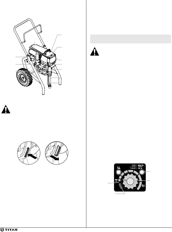
Pressure |
NOTE: Do not attach the tip to the spray gun yet. Remove |
||
Motor |
control knob |
|||
(reverse side) |
|
the tip if it is already attached. |
||
|
Digi-Trac™ Screen |
|
Make sure all airless hoses and spray guns are |
|
|
(reverse side) |
|
electrically grounded and rated at or above the |
|
Filter |
|
|
maximum operating pressure range of the airless |
|
|
|
sprayer. |
||
assembly |
Oiler Cap |
4. Make sure the pressure control knob is in its OFF position in |
||
PRIME / |
Oiler button |
|||
|
the black zone. |
|||
SPRAY Valve |
Fluid section |
5. |
Make sure the ON/OFF switch is in its OFF position. |
|
Outlet |
||||
6. |
Remove the fill cap with a straight-slot screwdriver, or a coin. |
|||
|
||||
tting |
|
|||
|
|
Fill the oil reservoir with one ounce of piston seal lubricant |
||
|
|
|
||
|
Siphon tube |
|
(Piston Lube). Replace oiler cap. |
|
|
Return tube |
7. |
Press oiler button 2-5 times to prime the oiler. Press once for |
|
|
|
every eight hours of usage to lubricate the fluid section. |
||
|
|
|
||
|
|
Important: Never operate unit for more than ten seconds |
||
|
|
without fluid. Operating this unit without fluid will cause |
||
|
|
unnecessary wear to the packings. |
||
Operation |
|
8. |
Make sure the electrical service is 120V, 15 amp minimum. |
|
|
9. Plug the power cord into a properly grounded outlet at least |
|||
|
|
|||
This equipment produces a fluid stream at extremely |
|
25’ from the spray area. |
||
Important: Always use a minimum 12 gauge, three-wire |
||||
high pressure. Read and understand the warnings |
||||
in the Safety Precautions section at the front of this |
extension cord with a grounded plug. Never remove the third |
|||
manual before operating this equipment. |
prong or use an adapter. |
|||
Using the Gun Trigger Lock |
|
|
|
|
Always engage the gun’s trigger lock when the gun is not in use. |
Preparing a New Sprayer |
|||
1. To lock the trigger, push in the trigger lock from left to right, |
If this sprayer is new, it is shipped with test fluid in the fluid section to |
|||
when looking at the rear of the gun. |
|
prevent corrosion during shipment and storage. This fluid must be |
||
2.To unlock the trigger, push the trigger lock from right to left, thoroughly cleaned out of the system with mineral spirits before you
when looking at the rear of the gun. |
begin spraying. |
|
||
1 |
2 |
Important: Always keep the trigger lock on the spray gun in |
||
the locked position while preparing the system. |
|
|||
|
|
1. |
Place the siphon tube into a container of mineral spirits. |
|
|
|
2. |
Place the return hose into a metal waste container. |
|
|
|
3. |
Set the pressure to minimum by turning the pressure control |
|
|
|
|
knob to the “MIN” setting. |
|
Gun locked |
Gun unlocked |
|
|
|
(gun will not spray) |
(gun will spray) |
|
|
Pressure |
|
|
|
|
|
|
|
|
|
Indicator |
|
|
|
Pump OFF |
Pressure |
|
|
|
Control Knob |
|
|
|
|
RAPID |
|
|
|
|
CLEAN |
|
|
|
|
RapidClean |
|
|
|
4. |
Move the PRIME/SPRAY valve down to the PRIME position. |
|
|
|
5. |
Turn on the sprayer by moving the ON/OFF switch to the ON |
|
|
|
|
position. |
|
|
|
6. |
Allow the sprayer to run for 15–30 seconds to flush the |
|
|
|
|
test fluid out through the return hose and into the waste |
|
|
|
|
container. |
|
|
|
7. |
Turn off the sprayer by moving the ON/OFF switch to the OFF |
|
|
|
|
position. |
|
English |
4 |
© Titan Tool Inc. All rights reserved. |
|
|
|

Preparing to Paint
Before painting, it is important to make sure that the fluid in the system is compatible with the paint that is going to be used.
NOTE: Incompatible fluids and paint may cause the valves to become stuck closed, which would require disassembly and cleaning of the sprayer’s fluid section.
Important: Always keep the trigger lock on the spray gun in the locked position while preparing the system.
1.Place the siphon tube into a container of the appropriate solvent. Examples of the appropriate solvent are water for latex paint or mineral spirits for oil-based paints.
2.Place the return hose into a metal waste container.
3. |
Set the pressure to minimum by turning |
|
|
|
the pressure control knob to the “MIN” |
|
|
|
setting. |
RAPID |
|
4. |
Move the PRIME/SPRAY valve down to |
||
CLEAN |
the PRIME position.
NOTE: Hold the return hose in the waste container when moving the PRIME/ SPRAY valve to PRIME in case the sprayer is pressurized.
5.Turn on the sprayer by moving the ON/OFF switch to the ON position.
6.Allow the sprayer to run for 15–30 seconds to flush the old solvent out through the return hose and into the metal waste container.
7.Turn off the sprayer by moving the ON/OFF switch to the OFF position.
NOTE: Make sure that the spray gun does not have a tip or tip guard installed.
8.Move the PRIME/SPRAY valve up to the SPRAY
position.
9. Turn on the sprayer.
10. Unlock the gun by pushing the gun trigger lock to the unlocked position.
Ground the gun by holding it against the edge of the metal container while flushing. Failure to do so may lead to a static electric discharge, which may cause a fire.
11.Trigger the gun into the metal waste container until the old solvent is gone and fresh solvent is coming out of the gun.
12.Lock the gun by pushing the gun trigger lock to the locked position.
13.Set down the gun and increase the pressure by turning the pressure control knob slowly clockwise.
14.Check the entire system for leaks. If leaks occur, follow the “Pressure Relief Procedure” in this manual before tightening any fittings or hoses.
15.Follow the “Pressure Relief Procedure” in this manual before changing from solvent to paint.
Be sure to follow the pressure relief procedure when shutting down the sprayer for any purpose, including servicing or adjusting any part of the spray system, changing or cleaning spray tips, or preparing for cleanup.
Painting
1.Place the siphon tube into a container of paint.
2.Place the return hose into a metal waste container.
3.Set the pressure to minimum by turning the pressure control knob to the “MIN” setting.
4.Move the PRIME/SPRAY valve down to the PRIME position.
5.Turn on the sprayer by moving the ON/OFF switch to the ON position.
6.Allow the sprayer to run until paint is coming through the return hose into the metal waste container.
7.Turn off the sprayer by moving the ON/OFF switch to the OFF position.
8.Remove the return hose from the waste container and place it in its operating position above the container of paint.
9.Move the PRIME/SPRAY valve up to the SPRAY position.
10.Turn on the sprayer.
11.Unlock the gun by turning the gun trigger lock to the unlocked position.
Ground the gun by holding it against the edge of the metal container while flushing. Failure to do so may lead to a static electric discharge, which may cause a fire.
12.Trigger the gun into the metal waste container until all air and solvent is flushed from the spray hose and paint is flowing freely from the gun.
13.Lock the gun by pushing the gun trigger lock to the locked position.
14.Turn off the sprayer.
15.Attach tip guard and tip to the gun as instructed by the tip guard or tip manuals.
POSSIBLE INJECTION HAZARD. Do not spray without the tip guard in place. Never trigger the gun unless the tip is in either the spray or the unclog position. Always engage the gun trigger lock before removing, replacing or cleaning tip.
16.Turn on the sprayer.
17.Increase the pressure by turning the pressure control knob slowly clockwise and test the spray pattern on a piece of cardboard. Adjust the pressure control knob until the spray from the gun is completely atomized. Try to keep the pressure control knob at the lowest setting that maintains good atomization.
NOTE: Turning the pressure up higher than needed to atomize the paint will cause premature tip wear and additional overspray.
© Titan Tool Inc. All rights reserved. |
5 |
English |
|
|
|
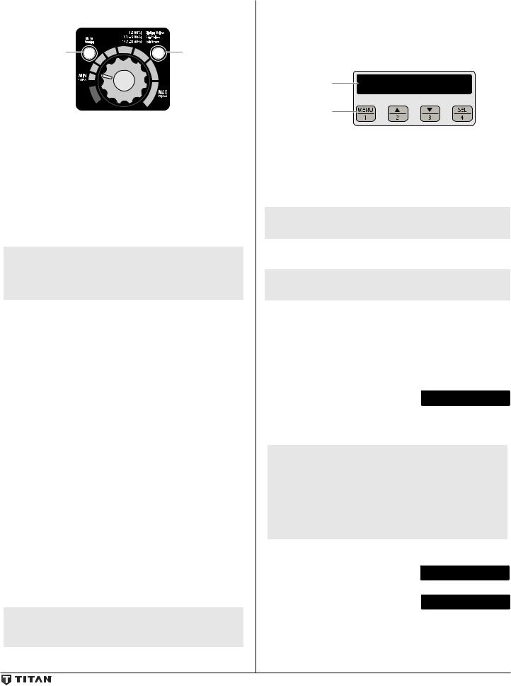
Control Panel Indicators
The following is a description of the control panel indicators.
Motor |
Pressure |
Running |
Indicator |
Indicator |
|
RAPID
CLEAN
Pressure Indicator
The pressure indicator shows the current operating pressure of the sprayer. It has three different indications: blinking yellow, solid yellow, and solid green.
Blinking Yellow
When the pressure indicator is blinking yellow, the sprayer is operating between 0 and 200 PSI. A blinking yellow pressure indicator means:
•The sprayer is plugged in and turned “ON”
•The sprayer is at priming pressure (little or no pressure)
•It is safe to move the PRIME/SPRAY valve between positions
•It is safe to change or replace the spray tip
NOTE: If the pressure indicator begins blinking yellow when the pressure control knob is set at a higher pressure and the PRIME/SPRAY valve is in the SPRAY position, either the spray tip is worn or the sprayer is in need of service/repair.
Solid Yellow
When the pressure indicator is solid yellow, the sprayer is operating between 201 and 1900 PSI. A solid yellow pressure indicator means:
•The sprayer is at the proper pressure setting for spraying stain, lacquer, varnish, and multi-colors
•If the pressure indicator goes to solid yellow when the pressure is set so that it starts at solid green, it indicates one of the following:
a.Tip Wear Indicator — when spraying with latex or at high pressure the solid yellow appears. This means the tip is worn and needs to be replaced.
b.Tip Too Large — when a tip that is too large for the sprayer is put in the gun, the pressure indicator will turn from solid green to solid yellow.
c.Fluid Section Wear — if a solid yellow pressure indicator appears when using a new tip and the pressure is set at maximum, service may be required (worn packings, worn piston, stuck valve, etc...).
Solid Green
When the pressure indicator is solid green, the sprayer is operating between 1901 and 3300 PSI. A solid green pressure indicator means:
•The sprayer is at the proper pressure setting for spraying oilbased and latex house paints
•The sprayer is operating at peak performance at a high pressure setting
Motor Running Indicator
The Motor Running indicator is on when the motor is commanded to run. This indicator is used by service centers to troubleshoot motor problems.
NOTE: If the motor running and pressure indicators blink alternately, it means the motor has overheated. Turn pump OFF and allow to cool.
Digi-Trac™ Control System Operation
The Digi-Trac™ Control System is an optional add-on that increases the functionality of the sprayer. It is installed directly below the pressure control knob on the control panel. It consists of a display and four function keys. The display shows various menu screens that allow the user to customize and monitor sprayer operation using the function keys.
Display |
SET PSI |
3000 |
|
ACTUAL PSI |
2950 |
Function
Keys
Function Keys
The function keys are numbered 1–4. Each key is labeled with an additional function as well.
#1/Menu Key |
Pressing the #1 key scrolls through the available |
|
menu screens or performs a function described |
|
on the active menu screen. |
#2/pKey |
Pressing the #2 key performs a function |
|
described on the active menu screen or increases |
|
a value. |
#3/qKey |
Pressing the #3 key performs a function |
|
described on the active menu screen or decrease |
|
a value. |
#4/Select Key |
Pressing the #4 key selects the active menu |
|
screen or performs a function described on the |
|
active menu screen. |
Menu Screens
Several menu screens are available for the user to customize and monitor sprayer operation. They include Main Screen, User PreSets, Volume Pumped, Job Volume, Unit Serial #, TImers, Job Timers, Service Time, Security Code, Prime, and RAPID CLEAN.
Main Screen
The Main Screen is the default screen for |
SET PSI |
3000 |
the control system at sprayer startup. |
ACTUAL PSI |
2950 |
|
|
Pressing the #2 key switches between PSI, Bar, and MPa units of measure. Press the #1 key to scroll through the remaining menu screens.
NOTE: For sprayers with serial numbers “15xxx01001” and higher, you are able to change the display text language by following the below procedure.
Pressing the #3 key at the Main Screen changes the language of the text on the display. There are a total of nine languages available. Each time the #1 key is pressed, a different language will appear.
The languages, in order of appearance, are: English, Spanish, Dutch, Danish, Swedish, German, French, Italian, and Portuguese.
Volume Pumped Screen
The Volume Pumped screen shows the |
VOLUME PUMPED |
|
total number of gallons or liters sprayed |
MENU-1 |
SELECT-4 |
by the sprayer. |
|
|
To select the Volume Pumped screen, |
GALLONS |
X |
press the #4 key. |
MENU-1 |
|
|
|
|
English |
6 |
© Titan Tool Inc. All rights reserved. |
|
|
|

Job Volume Screen
The Job Volume screen allows the user to |
JOB VOLUME |
|
reset a gallon counter to track usage on |
MENU-1 |
SELECT-4 |
specific jobs. |
|
|
To select the Job Volume screen, press |
JOB GAL |
XXXX |
the #4 key. |
MENU-1 |
RESET-3 |
|
|
|
Unit Serial # Screen
The Unit Serial # screen shows the |
UNIT SERIAL # |
|
sprayers serial number. |
MENU-1 |
SELECT-4 |
|
|
|
To select the Unit Serial # screen, press the #4 key.
Timers Screen
The Timers screen shows the total time the sprayer has been turned on as well as the total time the sprayer has been running (pumping).
SER # XXXXXXXXXX MENU-1
TIMERS
MENU-1 SELECT-4
To select the Timers screen, press the #4 |
ON TIME |
XXXX |
key. |
RUN TIME |
XXXX |
|
|
|
|
|
|
Job Timers Screen
The Job Timers screen allows the user to |
JOB TIMERS |
|
reset the “ON TIME” and “RUN TIME” to |
MENU-1 |
SELECT-4 |
track time on specific jobs. |
|
|
To select the Job TImers screen, press |
JOB ON |
X |
the #4 key. “JOB ON” screen will appear. |
MENU-1 |
RESET-3 |
Press #3 to reset. Press #1 to continue to |
JOB RUN |
X |
“JOB RUN” screen. Press #3 to reset. Press |
MENU-1 |
RESET-3 |
#1 to scroll through the remaining menu screens.
Service Time Screen
The Service Time screen allows the user to set a service time interval (in hours).
Below the set time, the screens shows the current amount of hours on the sprayer since the last activation of the service timer. To select the Service Timer screen, press the #4 key.
SERVICE TIME
MENU-1 SELECT-4
To set the service time, press the #2 (up) |
SERVICE @ |
XX |
and/or the #3 (down) keys to the desired |
RUN HOURS |
XX |
time (run hours will increase/decrease in |
|
|
increments of 25 for each time you press |
|
|
a key). |
|
|
When the sprayer reaches the SERVICE@ time selected, the screen will display “SERVICE DUE”. To reset the timer, press the #3 key when the pump is first turned on. This will reset the “SERVICE DUE” message and also reset the “SERVICE TIME” to the previous setting.
Security Code Screen
The Security Code screen allows the |
SECURITY CODE |
|
user to set a four digit security code to |
MENU-1 |
CHANGE-2 |
prevent unauthorized use of the sprayer. If a security code has been set, the control system display will ask for the code at startup. If the correct code is entered, the display will show the Main Screen and the sprayer will operate. If the wrong code is entered, the display will continue to ask for the correct code and the sprayer will not work. To set or change the security code, press the #2 key.
NOTE: If the sprayer is new, no security code is set and the Main Screen will appear at startup. When setting a security code for the first time, the “Enter Old Code Number” screen will appear, and you will need to enter “1111”.
Enter the old security code number to access the screen that allows the code change. If the wrong code is entered, the display will continue to ask for the correct
code and the security code cannot be changed.
Enter the new security code. Once the new code is entered, the display will automatically ask that the new code be re-entered for verification. If the same new code is re-entered, the display will confirm that the new code has been accepted and return to the Main Screen.
If the new code is re-entered incorrectly, the display will return to the
“Enter New Code Number” screen and the process will repeat.
If you forget or misplace your security code, you can call Titan customer service for assistance.
NOTE: To inactivate the Anti-Theft Digital Lockout security function, enter “1111” at the “Enter New Code Number” screen (this is the default code that leaves the sprayer unlocked). As a result, the Main Screen will appear at sprayer startup.
Prime Screen
The Prime screen appears when the pressure control knob is set at the “MIN” setting.
Rapid Clean Screen
The Rapid Clean screen appears when the pressure control knob is set at the RAPID
CLEAN position and the PRIME/SPRAY valve is in the PRIME position.
NOTE: If there is no action at any menu screen for 30 seconds, the display will go back to the Main Screen.
Pressure Relief Procedure
Be sure to follow the pressure relief procedure when shutting down the sprayer for any purpose, including servicing or adjusting any part of the spray system, changing or cleaning spray tips, or preparing for cleanup.
1.Lock the gun by pushing the gun trigger lock to the locked position.
2.Turn off the sprayer by moving the ON/OFF switch to the OFF position.
3.Turn the pressure control knob counterclockwise to its OFF position in the black zone.
4.Unlock the gun by pushing the gun trigger lock to the
unlocked position.
5. Hold the metal part of the gun firmly to the side of a metal container to ground the gun and avoid a build up of static electricity.
6. Trigger the gun to remove any pressure that may still be in the hose.
7.Lock the gun by pushing the gun trigger lock to the locked position.
8. Move the PRIME/SPRAY valve down to the PRIME position.
© Titan Tool Inc. All rights reserved. |
7 |
English |
|
|
|

Spraying
POSSIBLE INJECTION HAZARD. Do not spray without the tip guard in place. Never trigger the gun unless the tip is in either the spray or the unclog position. Always engage the gun trigger lock before removing, replacing, or cleaning tip.
Spraying Technique
The following techniques, if followed, will assure professional painting results.
Hold the gun perpendicular to the surface and always at equal distance from the surface. Depending on the type of material, surface, or desired spray pattern, the gun should be held at a distance of 12 to 14 inches (30 to 35 cm).
Move the gun either across or up and down the surface at a steady rate. Moving the gun at a consistent speed conserves material and provides even coverage. The correct spraying speed allows a full, wet coat of paint to be applied without runs or sags.
Holding the gun closer to the surface deposits more paint on the surface and produces a narrower spray pattern. Holding the gun farther from the surface produces a thinner coat and wider spray pattern. If runs, sags, or excessive paint occur, change to a spray tip with a smaller orifice. If there is an insufficient amount of paint on the surface or you desire to spray faster, a larger orifice tip should be selected.
Maintain uniform spray stroke action. Spray alternately from left to right and right to left. Begin movement of the gun before the trigger is pulled.
start |
pull |
release |
end |
stroke |
trigger |
trigger |
stroke |
|
|
|
|
Avoid arcing or holding the gun at an angle. This will result in an uneven finish.
O spray
Too Thick
Arcing |
Gun at angle |
Proper lapping (overlap of spray pattern) is essential to an even finish.
Lap each stroke. If you are spraying horizontally, aim at the bottom edge of the preceding stroke, so as to lap the previous pattern by 50%.
Overlap edges
1st |
2nd |
3rd |
4th |
5th |
pass |
pass |
pass |
pass |
pass |
For corners and edges, split the center of the spray pattern on the
corner or edge and spray vertically
so that both adjoining sections receive approximately even amounts of paint.
When spraying with a shield, hold
it firmly against the surface. Angle the spray gun slightly away from the shield and toward the surface. This will prevent paint from being forced underneath.
Shrubs next to houses should be tied back and covered with a canvas cloth. The cloth should be removed as soon as possible. Titan gun extensions are extremely helpful in these situations.
Nearby objects such as automobiles, outdoor furniture, etc. should be moved or covered whenever in the vicinity of a spray job. Be careful of any other surrounding objects that could be damaged by overspray.
Practice
1.Make sure that the paint hose is free of kinks and clear of objects with sharp cutting edges.
3.Set the pressure to minimum by turning the pressure control knob to the “Min” setting in the yellow zone.
3.Move the PRIME/SPRAY valve up to its SPRAY position.
4.Turn the pressure control knob clockwise to its highest setting in the green zone. The paint hose should stiffen as paint begins to flow through it.
5.Unlock the gun trigger lock.
6.Trigger the spray gun to bleed air out of the hose.
7.When paint reaches the spray tip, spray a test area to check the spray pattern.
8.Use the lowest pressure setting necessary to get a good spray pattern. If the pressure is set too high, the spray pattern will be too light. If the pressure is set too low, tailing will appear or the paint will spatter out in gobs rather than in a fine spray.
Good spray pattern
Paint tailing pattern
English |
8 |
© Titan Tool Inc. All rights reserved. |
|
|
|

Cleanup
Special cleanup instructions for use with flammable solvents:
•Always flush spray gun preferably outside and at least one hose length from spray pump.
•If collecting flushed solvents in a one gallon metal container, place it into an empty five gallon container, then flush solvents.
•Area must be free of flammable vapors.
•Follow all cleanup instructions.
Important: The sprayer, hose, and gun should be cleaned thoroughly after daily use. Failure to do so permits material to build up, seriously affecting the performance of the unit.
Always spray at minimum pressure with the gun nozzle tip removed when using mineral spirits or any other solvent to clean the sprayer, hose, or gun. Static electricity buildup may result in a fire or explosion in the presence of flammable vapors.
1.Follow the “Pressure Relief Procedure” found in the Operation section of this manual.
2.Remove the gun tip and tip guard and clean with a brush using the appropriate solvent.
3.Place the siphon tube into a container of the appropriate solvent. Examples of the appropriate solvent are water for latex paint or mineral spirits for oil-based paints.
4.Place the return hose into a metal waste container.
5.Move the PRIME/SPRAY valve down to its PRIME position.
NOTE: Hold the return hose in the waste container when moving the PRIME/SPRAY valve to PRIME in case the sprayer is pressurized.
6. |
Set the pressure to rapid clean by turning |
|
|
the pressure control knob to its rapid |
|
|
CLEAN position. |
|
7. |
Turn on the sprayer by moving the ON/OFF |
RAPID |
|
switch to the ON position. |
CLEAN |
|
|
8.Allow the solvent to circulate through the
unit and flush the paint out of the return hose into the metal waste container.
9.Turn off the sprayer by moving the ON/OFF switch to the OFF position.
10.Move the PRIME/SPRAY valve up to its SPRAY position.
11.Turn on the sprayer.
Ground the gun by holding it against the edge of the metal container while flushing. Failure to do so may lead to a static electric discharge, which may cause a fire.
12.Trigger the gun into the metal waste container until the paint is flushed out of the hose and solvent is coming out of the gun.
13.Continue to trigger the spray gun into the waste container until the solvent coming out of the gun is clean.
NOTE: For long-term or cold weather storage, pump mineral sprits through the entire system.
For short-term storage when using latex paint, pump water mixed with Titan Liquid Shield through the entire system (see the Accessories section of this manual for part number).
14.Follow the “Pressure Relief Procedure” found in the Operation section of this manual.
15.Unplug the unit and store in a clean, dry area.
Important: Do not store the unit under pressure.
Maintenance
Before proceeding, follow the Pressure Relief Procedure outlined previously in this manual. Additionally, follow all other warnings to reduce the risk of an injection injury, injury from moving parts or electric shock. Always unplug the sprayer before servicing!
General Repair and Service Notes
The following tools are needed when repairing this sprayer:
Phillips Screwdriver |
3/8” Hex Wrench |
Needle Nose Pliers |
5/16” Hex Wrench |
Adjustable Wrench |
1/4” Hex Wrench |
Rubber Mallet |
3/16” Hex Wrench |
Flat-blade Screwdriver |
5/32” Hex Wrench |
|
5/64” Hex Wrench |
1.Before repairing any part of the sprayer, read the instructions carefully, including all warnings.
Important: Never pull on a wire to disconnect it. Pulling on a wire could loosen the connector from the wire.
2.Test your repair before regular operation of the sprayer to be sure that the problem is corrected. If the sprayer does not operate properly, review the repair procedure to determine if everything was done correctly. Refer to the Troubleshooting Charts to help identify other possible problems.
3.Make certain that the service area is well ventilated in case solvents are used during cleaning. Always wear protective eyewear while servicing. Additional protective equipment may be required depending on the type of cleaning solvent. Always contact the supplier of solvents for recommendations.
4.If you have any further questions concerning your Titan Airless Sprayer, call titan:
Customer Service (U.S.)...................................... |
1-800-526-5362 |
Fax .................................................................. |
1-800-528-4826 |
© Titan Tool Inc. All rights reserved. |
9 |
English |
|
|
|

Replacing the Filters
Pump Filter
1.Loosen and remove the filter body by hand.
2.Slip the filter off of the core spring.
3.Inspect the filter. Based on inspection, clean or replace the filter.
4.Inspect the o-ring. Based on inspection, clean or replace the o-ring.
5.Slide the new or cleaned filter over the core spring with the filter spring adapter in place.
Push the filter into the center of the filter housing.
6.Slide the filter body over the filter and thread it into the filter housing until secure.
NOTE: The filter housing should be handtightened, but make sure the filter housing is seated fully into the pump block.
Gun Filter
Filter Body
Filter Spring
Filter
Filter Spring
Adapter
Core Spring
O-ring
Filter Housing
1.Unclip the top of the trigger guard from the gun body.
2.Using the bottom of the trigger guard as a wrench, loosen and remove the handle assembly from the gun head.
3.Pull the old filter out of the gun body. Clean or replace.
4.Slide the new filter, tapered end first, into the gun head.
5.Thread the handle assembly into the gun head. Tighten with the trigger wrench.
6.Snap the trigger guard back onto the gun body.
Gun
Body
Filter
Handle
NOTE: For more detail, part number information, and complete assembly drawings, please see the RX-Pro Airless Gun Owner’s Manual.
Replacing the Motor Assembly
1.Unplug the unit.
2.Loosen and remove the two (2) motor shroud screws. Remove the motor shroud.
3.Loosen and remove the three (3) belly pan screws. Remove the belly pan.
4.Loosen and remove the two (2) motor cover screws. Remove the motor cover.
5.Disconnect all wires between the motor and the sprayer.
6.Loosen and remove the four (4) control panel screws. Remove the control panel.
7.Disconnect the wires between the motor and the control panel.
8.Loosen and remove the two (2) motor controller screws.
Remove the motor controller.
9.Loosen and remove the four (4) motor baffle screws. Remove the motor baffle.
10.Loosen and remove the three (3) motor mounting screws.
11.Pull the motor out of the gearbox housing.
12.With the motor removed, inspect the gears in the gearbox housing for damage or excessive wear. Replace the gears, if necessary.
13.Install the new motor into the gearbox housing.
14.Secure the motor with the three (3) motor mounting screws.
15.Reconnect the wires between the sprayer and the new motor.
(refer to the electrical schematic in the Parts List section of this manual).
16.Place the baffle over the end of the motor assembly. Secure with the four (4) motor baffle screws.
17.Place motor controller back into place behind the motor baffle. Secure with the two (2) motor controller screws.
18.Reconnect all wires between the motor and sprayer.
19.Reconnect the wires between the motor and the control panel.
20.Replace control panel and secure with four (4) control panel screws.
21.Place the motor cover back over the motor controller. Secure with the two (2) motor cover screws.
22.Put the belly pan back in place and secure with the three (3) belly pan screws.
23.Slide the motor shroud over the motor assembly.
24.Secure the motor shroud with the two (2) motor shroud screws.
Control |
Gearbox |
Motor Shroud |
Panel |
housing |
|
Screw |
|
Motor Mounting |
|
|
Screw |
|
|
Motor |
Control |
|
|
Panel |
|
Motor |
|
|
|
Belly Pan |
|
Ba e |
Screw |
Motor |
Motor Ba e |
Belly Pan |
Shroud |
Screw |
Screw |
|
Motor Controller
Motor Controller Screw
Motor Cover
Motor Cover Screw
English |
10 |
© Titan Tool Inc. All rights reserved. |
|
|
|

Replacing the Gears
1.Follow steps 1-11 in Replacing the Motor Assembly (page 10) to remove the motor and control panel.
2.Inspect the armature gear on the end of the motor for damage or excessive wear. If the gear is completely worn out, replace the motor assembly.
3.Remove and inspect the 1st stage gear and 2nd stage gear assemblies for damage or excessive wear. Replace, if necessary.
4.Inspect the front gear box assembly for damage or excessive wear. If damaged or worn, replace the front gear box assembly.
NOTE: Clean and refill the gear box cavity up to the rear face of each gear with Lubriplate (P/N 314-171).
5.Reinstall the motor into the gearbox housing.
6.Follow steps 13-24 in Replacing the Motor Assembly (page 10) to replace the motor and control panel.
Armature Gear
2nd Stage Gear 3rd Stage Pinion
1st Stage Gear 2nd Stage Pinion
Belly Pan Screw
Belly Pan
Front Gear Box Assembly
Replacing the Transducer
1.Unplug the unit.
2.Loosen and remove the two (2) filter assembly bolts. Slide the filter assembly from the cart.
3.Loosen and remove the
two (2) motor shroud screws. Remove the motor shroud.
4.Loosen and remove the two (2) motor cover screws. Remove the motor cover.
5.Disconnect the transducer wire from the motor controller.
6.Pull the grommet out of the mounting plate and slide it up the shaft of the transducer until it is clear of the mounting plate.
7.Using a wrench, loosen and remove the transducer from the filter housing. Carefully thread the transducer wire out through the mounting plate.
8.Slide the grommet off of the old transducer and onto the new transducer.
9.Thread the new transducer wire through the mounting plate and back to the motor controller.
10.Thread the new transducer into the filter housing and tighten securely with a wrench.
NOTE: Make sure the o-ring on the transducer is in place before threading the transducer into the filter housing.
11.Push the grommet into the mounting plate.
12.Connect the transducer wire to the motor controller (refer to the electrical schematic in the Parts List section of this manual).
13.Place the motor cover back over the motor controller. Secure with the two (2) motor cover screws.
14.Slide the motor shroud over the motor assembly.
15.Secure the motor shroud with the two (2) motor shroud screws.
Motor Shroud
Motor |
Motor |
Cover |
Controller |
Screw |
|
Motor |
|
Cover |
|
Motor |
|
Shroud |
|
Screw |
|
Grommit
Tranducer
 Filter assembly
© Titan Tool Inc. All rights reserved. |
11 |
English |
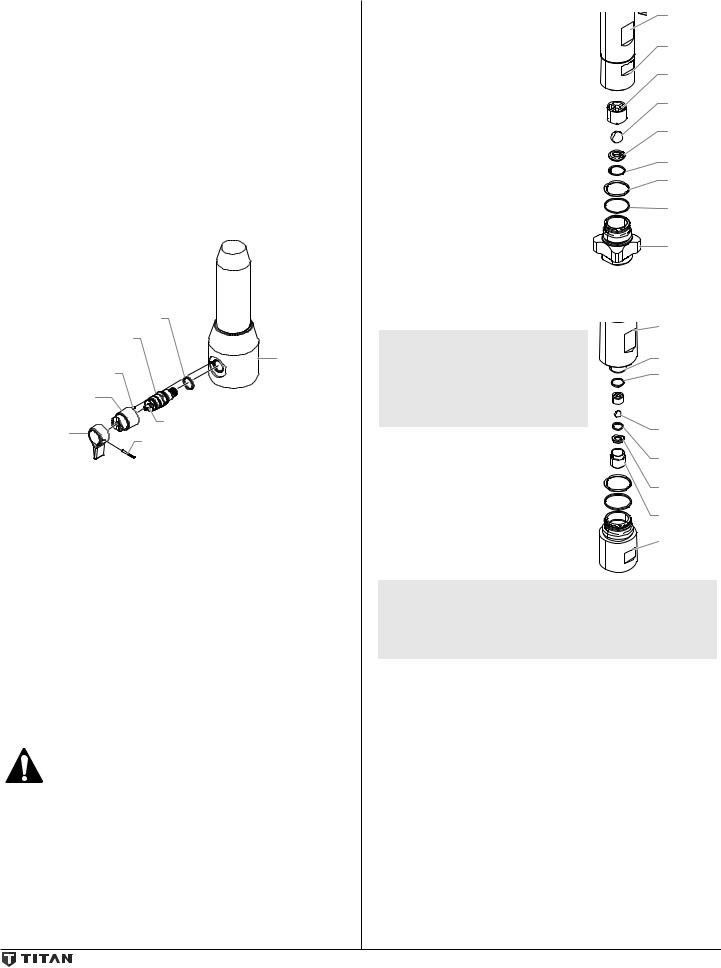
Replacing the prime/spray Valve
Perform the following procedure using PRIME/SPRAY valve replacement kit (see Parts List).
1.Push the groove pin out of the valve handle.
2.Remove the valve handle and the cam base.
3.Using a wrench, loosen and remove the valve housing assembly.
4.Make sure the gasket is in place and thread the new valve housing assembly into the filter block. Tighten securely with a wrench.
5.Place the cam base over the valve housing assembly.
Lubricate the cam base with grease and line up the cam with the filter block using the dowel pin.
6.Line up the hole on the valve stem with the hole in the valve handle.
7.Insert the groove pin into the valve handle and through the valve stem to secure the valve handle in position.
Gasket |
||
Valve Housing |
|
|
Assembly |
Filter |
|
|
||
Dowel Pin |
Housing |
|
Cam Base |
|
|
Valve |
Valve Stem |
|
Groove Pin |
||
Handle |
||
Servicing the Fluid Section
Use the following procedures to service the valves and repack the fluid section. Perform the following steps before performing any maintenance on the fluid section.
1.Loosen and remove the four front cover screws. Remove the front cover.
2.Set the pressure to minimum by turning the pressure control knob to the “MIN” setting. The Digi-Trac™ screen should say
“PRIME”.
3.Press the #1 key on the Digi-Trac™ control panel. The “CREEP MODE” screen will now appear.
4.Slowly turn the pressure control knob clockwise to increase the pressure. The crankshaft/slider assembly will begin to move very slowly.
5.When it reaches the bottom, dead-center of its stroke, turn the pressure control knob back to the “MIN” setting. The crankshaft/slider assembly should stop.
6.Turn the pump off and unplug the unit.
Before proceeding, follow the Pressure Relief Procedure outlined previously in this manual. Additionally, follow all other warnings to reduce the risk of an injection injury, injury from moving parts or electric shock. Always unplug the sprayer before servicing!
7.Remove the return hose from the clamp on the siphon tube.
8.Unscrew the siphon tube/siphon set from the foot valve.
9.Loosen and remove the high-pressure hose from the nipple on the back of the upper housing of the fluid section.
Servicing the Valves |
Upper |
|
Housing |
||
The design of the fluid section allows |
||
Lower |
||
access to the foot valve and seat as well |
||
as the outlet valve and seat without |
Housing |
|
completely disassembling the fluid |
Foot Valve |
|
section. It is possible that the valves may |
Cage |
|
not seat properly because of debris stuck |
Foot Valve |
|
in the foot valve seat or outlet valve seat. |
||
Ball |
||
Use the following instructions to clean |
||
Foot Valve |
||
the valves and reverse or replace the |
||
seats. |
Seat |
|
1. Loosen and remove the foot valve |
O-ring |
|
housing from the lower housing. |
Viton |
|
2. Clean out any debris in the foot |
||
O-Ring |
||
valve housing and examine the |
||
PTFE |
||
housing and the foot valve seat. |
||
If the seat is damaged, reverse or |
Back-Up |
|
Ring |
||
replace the seat. |
||
Foot Valve |
||
3. Using two wrenches, hold the |
||
upper housing at the wrench flats |
Housing |
|
with one wrench and loosen the |
|
lower housing with the other. Remove the lower housing.
4.Using a 3/4” wrench, loosen and remove the outlet valve retainer from the piston rod.
NOTE: Always service the outlet valve with the piston rod attached to the pump. This will prevent the piston
rod from rotating during disassembly of the outlet valve.
5.Clean out any debris and examine the retainer and outlet valve seat. If the seat is damaged, reverse or replace the seat.
6.Remove, clean, and inspect the outlet valve cage and outlet valve ball. Replace if they are worn or damaged.
7.Reassemble the valves by reversing the steps above.
Upper
Housing
Piston Rod
Outlet Valve
Seal
 Outlet Valve
Cage
Outlet Valve
Ball
Nylon
Washer
Outlet Valve
Seat
Outlet Valve
Retainer
Lower
Housing
NOTE: During reassembly, make sure the Viton o-rings and the PTFE back-up rings between the upper housing and lower housing as well as between the lower housing and the foot valve housing are lubricated with grease and in position.
English |
12 |
© Titan Tool Inc. All rights reserved. |
|
|
|

Repacking the Fluid Section
1. Remove the foot valve assembly |
Crankshaft |
|
and the lower housing using |
|
|
the steps in the “Servicing the |
Slider |
|
Valves” procedure above. |
||
|
Assembly |
|
NOTE: The outlet valve does not |
|
|
need to be disassembled |
|
|
from the piston rod for |
|
|
this procedure. |
|
|
2. High rider models - turn the |
|
|
knob on the side of the cart |
|
|
clockwise to unlock the cart. Tilt |
|
|
the cart backwards until it locks |
Upper Seal |
|
into place. |
||
Retainer |
||
Low boy models - tilt the cart |
||
|
||
backward until it is vertical. |
Spacer |
|
3. Pull the lever on the underside |
||
|
||
of the sprayer toward the front |
Upper |
|
of the sprayer. This will un- |
Packing |
|
clamp the entire fluid section. |
|
|
Slide the fluid section forward |
|
|
to remove it from the gear |
|
|
housing. |
Upper |
|
4. Place the upper housing upright |
||
in a vise by clamping on the |
Housing |
|
wrench flats. |
|
|
NOTE: Do not over-tighten |
Lower |
|
the vise. Damage to |
Packing |
|
the upper housing may |
Wear Ring |
|
occur. |
||
|
||
5. Using a wrench, remove the |
|
|
upper seal retainer. |
Piston Rod |
|
6. Slide the piston rod forward |
||
|
||
until the piston is out of the |
|
|
T-slot on the slider assembly. |
|
7.Pull the piston out through the bottom of the upper housing.
8.Inspect the piston rod for wear and replace if necessary.
9.Remove the upper and lower packings from the upper housing.
NOTE: Be careful not to scratch, score, or otherwise damage the upper housing during removal of the packings.
10.Clean the upper housing. Inspect the upper housing for damage and replace if necessary.
11.Locate the new upper and lower packings and pack the areas between the packing lips with grease. Lubricate the o-rings on the exterior of the packings with grease.
12.Insert the upper packing into the top of the upper housing with the raised lip on the packing facing down.
13.Insert the spacer on top of the upper packing.
14.Thread the upper seal retainer into the upper housing and torque to 25-30 ft. lbs.
Install upper packing with raised lip facing down.
Raised Lip
15.Pre-form the lower packing using the lower packing sizing tool (included in the repacking kit).
16.Insert the lower packing partially into the bottom of the upper housing so that the side that has the o-ring closest to the face of the packing faces up.
17.Push the lower packing into position using the lower packing insertion tool (see Fluid Section Assembly parts list for lower packing insertion tool P/N).
Install lower packing with the side that has the o-ring closest to the face of the packing facing up.
Closer
Top
18.Place the piston insertion tool
(included in the repacking kit) over the top of the piston rod.
19.Insert the piston rod into the bottom of the upper housing, through the lower packing, through the upper packing, and out through the upper seal retainer.
NOTE: When repacking the fluid section, make sure the raised lip on the bottom of the lower packing is fully outside the packing around the piston rod after insertion of the piston rod.
20.Remove the piston insertion tool from the top of the piston rod.
21.Replace the upper housing back into the fluid section clamp on the gear housing. Make sure to slide the top of the piston rod into the T-slot on the slider assembly.
22.Push the lever on the underside of the unit toward the rear of the sprayer to lock the fluid section back into place.
28.Making sure that the Viton o-ring and PTFE back-up ring are lubricated and in place, thread the lower housing into the upper housing. Using two wrenches, hold the upper housing at the wrench flats with one wrench and tighten the lower housing with the other.
29.Attach the high-pressure hose to the nipple on the back of the housing and tighten with a wrench. Do not kink the hose.
NOTE: Make sure the hose does not touch the cart frame. If it does, reposition the nipple by turning the upper housing until the hose is clear of the frame and the nipple is within 45º of the back of the unit.
30.Making sure that the Viton o-ring and PTFE back-up ring are lubricated and in place, reassemble the foot valve assembly and and thread it into the lower housing. Tighten securely.
31.Thread the siphon tube/siphon set into the foot valve and tighten securely. Make sure to wrap the threads on the down tube/siphon tube adapter with PTFE tape before assembly.
32.Replace the return hose into the clamp on the siphon tube.
33.Place the front cover on the gearbox housing and secure in position using the four front cover screws.
34.Turn on the sprayer by following the procedure in the
“Operation” section of this manual and check for leaks.
NOTE: Repacking kit P/N 0558740 is available. For best results use all parts supplied in this kit.
© Titan Tool Inc. All rights reserved. |
13 |
English |
|
|
|

Troubleshooting
Problem
A.The unit will not run.
B.The unit will not prime.
C.The unit will not build or maintain pressure.
D.Fluid leakage at the upper end of the fluid section.
Cause
1.The unit is not plugged in.
2.Tripped breaker.
3.The pressure is set too low (pressure control knob set at minimum setting does not supply power to unit).
4.Faulty or loose wiring.
5.Excessive motor temperature.
6.ON/OFF switch is defective.
1.The PRIME/SPRAY valve is in the SPRAY position.
2.Air leak in the siphon tube/siphon assembly.
3.The pump filter and/or inlet screen is clogged.
4.The siphon tube/siphon assembly is clogged.
1.The spray tip is worn.
2.The spray tip is too large.
3.The pressure control knob is not set properly.
4.The pump filter, gun filter, or inlet screen is clogged.
5.Material flows from the return hose when the
PRIME/SPRAY valve is in the SPRAY position.
6.Air leak in the siphon tube/siphon assembly.
7.There is external fluid leak.
8.There is an internal fluid section leak (packings are worn and/or dirty, valve balls are worn).
9.Worn valve seats
10.Motor powers but fails to rotate
1.The upper packings are worn.
2.The piston rod is worn.
Solution
1.Plug the unit in.
2.Reset the breaker.
3.Turn the pressure control knob clockwise to supply power to the unit and increase the pressure setting.
4.Inspect or take to a Titan authorized service center.
5.Allow motor to cool.
6.Replace the ON/OFF switch.
1.Rotate the PRIME/SPRAY valve clockwise to the PRIME position.
2.Check the siphon tube/siphon assembly connection and tighten or re-tape the connection with PTFE tape.
3.Remove the pump filter element and clean. Remove the inlet screen and clean.
4.Remove the siphon tube/siphon assembly and clean.
1.Replace the spray tip following the instructions that came with the spray gun.
2.Replace the spray tip with a tip that has a smaller orifice following the instructions that came with the spray gun.
3.Turn the pressure control knob clockwise to increase the pressure setting.
4.Remove the pump filter element and clean. Remove the gun filter and clean. Remove the inlet screen and clean.
5.Clean or replace the PRIME/SPRAY valve.
6.Check the siphon tube/siphon assembly connection and tighten or re-tape the connection with PTFE tape.
7.Check for external leaks at all connections. Tighten connections, if necessary.
8.Clean the valves and service the fluid section following the “Servicing the Fluid Section” procedure in the Maintenance section of this manual.
9.Reverse or replace the valve seats following the “Servicing the Fluid Section” procedure in the Maintenance section of this manual.
10.Take unit to a Titan authorized service center.
1.Repack the pump following the “Servicing the Fluid Section” procedure in the Maintenance section of this manual.
2.Replace the piston rod following the “Servicing the Fluid Section” procedure in the Maintenance section of this manual.
E. |
Excessive surge at the spray |
1. |
Wrong type of airless spray hose. |
1. |
Replace hose with a minimum of 50’ of 1/4” grounded |
|||||
|
gun. |
|
|
|
|
|
textile braid airless paint spray hose. |
|||
|
|
|
2. |
The spray tip worn or too large. |
2. |
Replace the spray tip following the instructions that |
||||
|
|
|
|
|
|
|
|
came with the spray gun. |
||
|
|
|
3. |
Excessive pressure. |
3. |
Rotate the pressure control knob counterclockwise to |
||||
|
|
|
|
|
|
|
|
decrease spray pressure. |
||
|
|
|
|
|
|
|
|
|
|
|
|
|
|
1. |
The spray tip is too large for the material |
1. |
Replace the spray tip with a new or smaller spray tip |
||||
F. |
Poor spray pattern. |
|
being used. |
|
following the instructions that came with the spray gun. |
|||||
|
|
|
2. |
Incorrect pressure setting. |
2. |
Rotate the pressure control knob to adjust the pressure |
||||
|
|
|
|
|
|
|
|
for a proper spray pattern. |
||
|
|
|
3. |
Insufficient fluid delivery. |
3. |
Clean all screens and filters. |
||||
|
|
|
4. |
The material being sprayed is too viscous. |
4. |
Add solvent to the material according to the |
||||
|
|
|
|
|
|
|
|
manufacturer’s recommendations. |
||
|
|
|
|
|
|
|
|
|
|
|
|
|
|
1. |
The pressure adjustment is too low. |
1. |
Rotate the pressure control knob clockwise to increase |
||||
G. The unit lacks power. |
|
|
|
|
|
the pressure setting. |
||||
|
|
|
2. |
Improper voltage supply. |
2. |
Reconnect the input voltage for 120V AC. |
||||
|
English |
14 |
© Titan Tool Inc. All rights reserved. |
|
|
|
|

Digi-Trac™ Control System Error Messages
The following error message screens appear whenever the Digi-Trac
Control System detects a problem with the sprayer. Once a problem occurs and the error message appears, the sprayer will shut down.
Before proceeding, follow the Pressure Relief Procedure outlined previously in this manual. Additionally, follow all other warnings to reduce the risk of an injection injury, injury from moving parts or electric shock. Always unplug the sprayer before servicing!
Check Transducer Screen
The Check Transducer screen appears when the transducer has become
disconnected or is defective. Take the sprayer to a Titan authorized service center for repair.
Check Potentiometer Screen
The Check Potentiometer screen appears when the potentiometer has become disconnected or is defective. Take the sprayer to a Titan authorized service center for repair.
CHECK
POTENTIOMETER
Low Voltage Screen
The Low Voltage screen appears when |
LOW VOLTAGE |
the sprayer shuts down because of low |
|
input voltage. Check the power supply |
|
and correct the problem. Restart the |
|
sprayer by following the “Painting” |
|
procedure in the Operation section of this |
|
manual. |
|
|
|
High Motor Temperature Screen
The High Motor Temperature screen appears when the temperature of the motor has risen too high. Take the sprayer to a Titan authorized service center for repair.
HIGH MOTOR
TEMPERATURE
High Mechanical Load
The High Mechanical Load screen appears when the sprayer shuts down because
of high current or when the sprayer goes into current fold back mode. Take the sprayer to a Titan authorized service center for repair.
HIGH MECHANICAL
LOAD
High Control Temperature
Indicates the Digi-Trac is shut down due to excessive heat. Take the sprayer to a
Titan authorized service center for repair.
HIGH CONTROL
TEMPERATURE
Check Motor
Indicates the motor or motor hall affect |
CHECK MOTOR |
sensors are defective. Take the sprayer |
|
to a Titan authorized service center for |
|
repair. |
|
|
|
Bad Hall Cycle Power
Indicates the motor is shut down due to connection problems between the motor and controller. Take the sprayer to a Titan authorized service center for repair.
BAD HALL CYCLE
POWER
© Titan Tool Inc. All rights reserved. |
15 |
English |
|
|
|

Consignes de sécurite important
Lire toutes ces consignes avant d’utiliser l’appareil. Garder ces consignes.
Indique une situation à risque, laquelle, si elle n’est pas évitée, peut entraîner des blessures graves, voire la mort.
Pour réduire les risques d’incendie ou d’explosion, de choc électrique et de blessure, vous devez lire et comprendre les directives figurant dans ce manuel.
Familiarisez-vous avec les commandes et l’utilisation adéquate de l’équipement.
Directives de mise à la terre
Cet appareil doit être mis à la terre. En cas de court-circuit, cette précaution réduit les risques de choc en procurant un parcours au courant électrique. Le cordon de l’appareil est doté d’un fil de terre relié à la troisième broche de sa fiche. Cette dernière doit être branchée dans une prise correctement câblée et mise à la terre conformément aux codes et règlements locaux.
mise en garde - Le fait de ne pas brancher correctement la fiche trifilaire de l’appareil peut entraîner des risques de choc électrique.
Si on doit réparer ou remplacer le cordon ou la fiche, ne pas raccorder le fil de terre à la borne des broches plates (lames) de cette dernière. Ce fil,
normalement vert (avec ou sans rayures jaunes), doit être relié à la broche de terre.
Consulter un technicien ou un électricien qualifié à défaut de comprendre l’ensemble des présentes directives ou en cas d’incertitude quant à la mise à terre de l’appareil. Ne pas modifier la fiche de l’appareil; si elle ne s’adapte pas dans la prise voulue, la faire remplacer par un électricien qualifié.
Conçu pour les circuits de 120 V, cet appareil est doté d’une fiche ressemblant
à celle illustrée ci-dessous. S’assurer que le produit est connecté à une prise électrique ayant la même configuration que la fiche mâle. Ne pas utiliser d’adaptateur avec ce produit.
Prise tri laire
Broche de mise à la terre
 Plaque murale de la prise
important: Quand le pulvérisateur est utilisé avec un générateur de tension de la ligne ou non, l’utilisation de Titan “Line Surge Protector” (P / N 800-935) est recommandé.
MISE EN GARDE : EXPLOSION OU INCENDIE
Les émanations de certains produits peuvent exploser ou s’enflammer, et risquent d’entraîner des dommages matériels ou de graves blessures.
MESURES PRÉVENTIVES :
•Ne pulvérisez pas de matières inflammables ou combustibles près d’une flamme nue, de voyants lumineux ou de sources d’ignition telles que des objets chauds, cigarettes, moteurs, matériel et appareils
électriques. Évitez de produire des étincelles en connectant et en déconnectant les cordons électriques.
•S’entourer de toutes les précautions possibles lorsqu’on utilise des produits ayant un point d’éclair inférieur à 38°C (100°F). Le point d’éclair est la température à laquelle le liquide peut créer suffisamment de vapeurs et s’enflammer.
•L’écoulement de peinture ou de solvant dans l’équipement peut produire de l’électricité statique. L’électricité statique crée un risque d’incendie ou d’explosion en présence de fumées de peinture ou de solvant. Toutes les pièces du système du pulvérisateur, y compris la pompe, l’ensemble du tuyau, le pistolet de pulvérisation et les objets dans et autour de la zone de pulvérisation doivent être correctement reliés à la terre pour protéger contre les décharges d’électricité statique et les étincelles. N’utilisez que des tuyaux conducteurs ou reliés à la terre pour pulvérisateurs de peinture sous vide à haute pression, spécifiés par le fabricant.
•Vérifiez que tous les conteneurs ou systèmes de stockage sont reliés à la terre pour éviter les décharges d’électricité statique.
•Connectez à une prise électrique avec prise de terre et utilisez des rallonges électriques reliées à la terre. N’utilisez pas d’adaptateur 3 à 2.
•N’utilisez pas de peinture ou de solvant contenant du halon, par exemple, le chlore, les agents antimoisissure à l’eau de
Javel, le chlorure de méthylène et le trichloroéthane. Ils ne sont pas compatibles avec l’aluminium. Contactez le fournisseur de revêtements pour connaître la compatibilité du matériau avec l’aluminium.
•La zone de pulvérisation doit toujours être bien aérée. Une bonne quantité d’air frais doit constamment traverser la zone de
pulvérisation pour éviter les accumulations de vapeurs inflammables.
Le système de pompage doit être placé dans une zone bien aérée. Ne pulvérisez pas le système de pompage.
•Ne fumez pas dans la zone de pulvérisation.
•N’actionnez pas d’interrupteurs électriques, de moteurs ou autres dispositifs produisant des étincelles dans la zone de pulvérisation.
•Maintenez la propreté de la zone et veillez à ce qu’elle ne contienne pas de conteneurs de peinture ou de solvant, de chiffons et autres matières inflammables.
•Sachez ce que contiennent la peinture et les solvants pulvérisés. Lisez les fiches de sécurité du matériel (MSDS) et les étiquettes apposées sur les conteneurs de peintures et de solvants. Respectez les consignes de sécurité du fabricant de peinture et de solvant.
•Placez la pompe à une distance minimum de 7,62 mètres (25 pieds) de l’objet à pulvériser, dans une zone bien aérée (ajoutez de la longueur de tuyau si besoin est). Les vapeurs inflammables sont souvent plus lourdes que l’air. La zone près du sol doit être très bien aérée. La pompe contient des pièces qui produisent des arcs et émettent des étincelles pouvant enflammer les vapeurs.
•Le plastique peut causer des étincelles d’électricité statique. N’accrochez aucun plastique dans une zone de pulvérisation fermée. N’utilisez pas de toiles de protection en plastique quand vous pulvérisez une matière inflammable.
•Ayez un extincteur en bon état de fonctionnement à portée de main.
MISE EN GARDE : injection cutanée
Le jet de haute pression produit par cet appareil peut transpercer la peau et les tissus sous-jacents, causant des blessures graves pouvant entraîner l’amputation.
MESURES PRÉVENTIVES :
•Ne dirigez pas le pistolet sur et ne pulvérisez pas les personnes ou les animaux.
•N’approchez pas les mains ni d’autres parties du corps de la sortie du produit. Par exemple, ne tentez pas d’arrêter une fuite avec une partie du corps.
•NE JAMAIS mettre la main, même gantée, devant le pistolet (les gants n’offrent aucune protection contre les blessures par injection).
•TOUJOURS s’assurer que le protège-embout est en place avant de pulvériser. Il est cependant à noter que, s’il assure une certaine protection, ce dispositif joue surtout un rôle préventif.
•Utilisez exclusivement un embout de buse spécifié par le fabricant.
•Prenez garde quand vous nettoyez ou que vous changez les embouts de buse. Si l’embout se bouche pendant que vous pulvérisez, verrouillez TOUJOURS la détente du pistolet, arrêtez la pompe et libérez toute la pression avant de réparer ou de nettoyer l’embout ou le protecteur ou avant de changer d’embout. La pression n’est pas libérée par l’arrêt du moteur. La poignée du robinet-valve PRIME/ SPRAY doit être placée sur PRIME pour libérer la pression. Consultez la PROCÉDURE DE DÉcomPRESSION décrite dans le manuel de la pompe.
•Ne laissez pas l’appareil sous tension ou sous pression quand vous vous en éloignez. Quand vous n’utilisez pas l’appareil, éteignez-le et libérez la pression conformément aux instructions du fabricant.
•La pulvérisation à haute pression peut injecter des toxines dans le corps et causer de graves blessures corporelles. Si une telle injection se produisait, consultez immédiatement un médecin.
•Vérifiez les tuyaux et les pièces pour détecter des signes d’endommagement : une fuite peut injecter le produit dans la peau.
Inspectez le tuyau avant chaque emploi. Changez tous les tuyaux ou pièces endommagés. Pour des raisons de fonctionnement, de sécurité
Français |
16 |
© Titan Tool Inc. Tous droits réservés. |
|
|
|

Consignes de sécurite important
et de durée de vie, utiliser exclusivement des tuyaux flexibles à haute pression d‘origine de TITAN.
•Ce système peut produire une pression de 3 300 PSI / 228 Bar. N’utilisez que les pièces de rechange ou les accessoires spécifiés par le fabricant et ayant une pression nominale minimum de 3 300 PSI. Ceci est valable pour les embouts de pulvérisation, les protecteurs de buse, les pistolets, les rallonges, les raccords et le tuyau.
•Verrouillez toujours la détente quand vous ne pulvérisez pas. Vérifiez que le verrou de la détente fonctionne correctement.
•Vérifiez que toutes les connexions sont bien serrées avant d’utiliser l’appareil.
•Sachez comment arrêter l’appareil et le dépressuriser rapidement. Soyez bien familiarisé avec les commandes. La pression n’est pas libérée lorsque le moteur est arrêté. La poignée du robinet-valve PRIME/SPRAY doit être placée sur PRIME pour libérer la pression. Consultez la PROCÉDURE DE DÉcomPRESSION décrite dans le manuel de la pompe.
•Retirez toujours l’embout de pulvérisation avant de rincer ou de nettoyer le système.
remarque à l’intention des MÉDECINS : Les injections cutanées sont des lésions traumatiques; il importe donc de les traiter sans délai. On NE DOIT PAS retarder ce traitement sous prétexte de vérifier la toxicité du produit en cause, celle-ci n’étant conséquente que dans le cas d’injection directe de certains produits dans le système sanguin. Il pourrait s’avérer nécessaire de consulter un plasticien ou un spécialiste en chirurgie reconstructive de la main.
MISE EN GARDE : ÉMANATIONS DANGEREUSES
Certains produits (peintures, solvants, insecticides ou autres) peuvent être nocifs s’ils sont inhalés ou entrent en contact avec l’organisme. Les émanations de ces produits peuvent provoquer de graves nausées, évanouissements ou empoisonnements.
MESURES PRÉVENTIVES :
•Se servir d’un masque ou d’un respirateur s’il y a risque d’inhalation
(lire toutes les directives concernant ces dispositifs afin de s’assurer qu’ils offrent la protection requise).
•Porter des lunettes de protection.
•Porter les vêtements de protection prescrits par le fabricant du produit utilisé.
MISE EN GARDE : GÉNÉRALITÉS
D’autres dangers peuvent entraîner des dommages matériels ou des blessures graves.
MESURES PRÉVENTIVES :
•Portez toujours les gants, la protection oculaire, les vêtements et un respirateur ou masque appropriés quand vous peignez.
•Ne travaillez pas et ne pulvérisez pas près d’enfants. Éloignez toujours les enfants de l’équipement.
•Ne travaillez pas avec les bras au-dessus de la tête ni sur un support instable. Appuyez-vous bien sur les deux pieds pour toujours conserver l’équilibre.
•Soyez attentif et regardez ce que vous faites.
•N’utilisez pas l’appareil quand vous êtes fatigué ou sous l’influence de drogues ou d’alcool.
•Ne faites pas de nœuds avec le tuyau et ne le tordez pas trop. Le tuyau à vide peut présenter des fuites suite à l’usure, les nœuds ou les mauvais traitements. Une fuite risque d’injecter du produit dans la peau.
•N’exposez pas le tuyau à des températures ou des pressions supérieures à celles spécifiées par le fabricant.
•N’utilisez pas le tuyau pour tirer ou soulever l’équipement.
•Utilisez la plus basse pression possible pour rincer l’équipement.
•Respectez tous les codes locaux, étatiques et nationaux qui régulent la ventilation, la prévention d’incendies et le fonctionnement.
•Les normes de sécurité du gouvernement des États-Unis ont été adoptées dans la loi Occupational safety and Health Act (OSHA). Ces
normes, en particulier la partie 1910 des Normes générales et la partie 1926 des Normes de construction, doivent être consultées.
•Avant chaque emploi, vérifiez tous les tuyaux pour détecter d’éventuelles coupures, fuites, abrasion ou couvercle bombé. Vérifiez l’état ou le mouvement des accouplements. Changez immédiatement le tuyau si l’une de ces conditions est vérifiée. Ne réparez jamais un tuyau de peinture. Remplacez-le par un tuyau conducteur à haute pression.
•Ne pulvérisez pas à l’extérieur par temps venteux.
•Débranchez toujours le cordon électrique de la prise avant de travailler sur l’équipement.
Spécifications |
|
|
Débit (GPM) |
1,20 (4,54 LPM) |
|
Embout, dimension |
0,034” |
|
maximale |
|
|
Pression maximale |
3 300 PSI (22,8 MPa) |
|
Source de puissance |
2,6 HP moteur DC de Brushless, |
|
|
100~120V AC, 50/60Hz, 15A |
|
Poids, chariot |
103 lbs. (46,7 kg) |
|
Poids, bas chariot |
100 lbs. (45,3 kg) |
|
Cordon d’alimentation |
300’ (91,4 m) |
|
dimension maximale |
|
|
Génératrice |
5000 W (désactiver la mort en fonction) |
|
Table des matières |
|
|
Consignes de sécurité.................................................................... |
|
16 |
Specifications................................................................................. |
|
17 |
Description générale..................................................................... |
|
18 |
Fonctionnement............................................................................. |
|
18 |
Utilisation du blocage de la détente du pistolet............................. |
18 |
|
Vérifications préliminaires....................................................................... |
18 |
|
Préparation avant de peindre................................................................. |
19 |
|
Peinture.......................................................................................................... |
|
19 |
Panneau de contrôle indicateurs.......................................................... |
20 |
|
Fonctionnement du système de commande Digi-TracMD..... 20-21 |
||
Procédure de décompression................................................................ |
22 |
|
Vaporisation................................................................................... |
|
22 |
Technique de vaporisation...................................................................... |
22 |
|
Essais préliminaires..................................................................................... |
|
22 |
Nettoyage....................................................................................... |
|
23 |
Maintenance................................................................................... |
|
23 |
Généralités concernant la maintenance............................................. |
23 |
|
Remplacement des filtres......................................................................... |
24 |
|
Remplacement du moteur....................................................................... |
24 |
|
Remplacement des engrenages............................................................ |
25 |
|
Remplacement du transducteur............................................................ |
25 |
|
Remplacement de la soupape prime/Spray.................................. |
26 |
|
Maintenance de la section des liquides....................................... |
26-28 |
|
Dépannage..................................................................................... |
|
28 |
Messages d’erreur du système de commande Digi-TracMD............... |
29 |
|
Listes de pièces............................................................................... |
|
44 |
Vue d’ensemble........................................................................................... |
|
44 |
Boîte d’engrenages.................................................................................... |
|
46 |
Ensemble de chariot.................................................................................. |
|
47 |
Section des liquides................................................................................... |
|
48 |
Ensemble du filtre....................................................................................... |
|
50 |
Ensemble de basse chariot...................................................................... |
51 |
|
Ensemble d’aspiration (bas chariot)..................................................... |
52 |
|
Étiquettes....................................................................................................... |
|
52 |
Schéma de raccordement électrique................................................... |
53 |
|
Accessoires.................................................................................................... |
|
54 |
Enregistrement du produit........................................................... |
55 |
|
Garantie.......................................................................................... |
|
56 |
© Titan Tool Inc. Tous droits réservés. |
17 |
Français |
|
|
|
 Loading...