


0537010
Titan 0537010, 0537000, 0537005, 0537003, 0537001 User Manual
...
PowrBeast
Airless, high-pressure
sprAying unit
Airless hochdruckspritzgerät
operAting MAnuAl
- d - BetrieBsAnleitung 34
- F - Mode d’eMploi 66
groupe de projection à
hAute pression
Models:
PowrBeast 4700 (120V) 0537000
PowrBeast 4700 (Gas) 0537001
PowrBeast 7700 (230V) 0537003
PowrBeast 7700 (Gas) 0537005
PowrBeast 9700 (Gas) 0537007
PowrBeast 4700T (120V) 0537010
0217 • Form No. 0537810B
original operating manual
Airless units develop extremely high spraying pressures.
1
PowrBeast
Warning!
Attention: Danger of injury by injection!
Never put your ngers, hands or any other parts of the body into
the spray jet!
Never point the spray gun at yourself, other persons or animals.
Never use the spray gun without safety guard.
Do not treat a spraying injury as a harmless cut. In case of injury
to the skin through coating materials or solvents, consult a doctor
immediately for quick and expert treatment. Inform the doctor
about the coating material or solvent used.
2
3
The operating instructions state that the following points must
always be observed before starting up:
1. Faulty units must not be used.
2. Secure Titan spray gun using the trigger lock on the trigger.
3. Ensure that the unit is properly earthed.
4. Check allowable operating pressure of high-pressure hose and spray gun.
5. Check all connections for leaks.
The instructions regarding regular cleaning and maintenance of
the unit must be strictly observed.
Before any work is done on the unit or for every break in work the
following rules must be observed:
1. Release the pressure from spray gun and hose.
2. Secure the Titan spray gun using the trigger lock on the trigger.
3. Switch o unit.
Be safety conscious!
2

contents
PowrBeast
1 SAFETY REGULATIONS FOR AIRLESS
SPRAYING ______________________________ 4
1.1 Explanation of symbols used _____________________4
1.2 Safety hazards ________________________________4
1.3 Setup on an uneven surface _____________________6
1.4 Electrical safety _______________________________6
1.5 Gasoline engine safety__________________________6
1.6 Fueling (gas engine) ___________________________7
2 MAIN AREAS OF APPLICATION ____________ 8
2.1 Application ___________________________________ 8
2.2 Coating materials ______________________________ 8
3 DESCRIPTION OF UNIT ___________________ 9
3.1 Airless process ________________________________9
3.2 Functioning of the unit _________________________9
3.3 System diagram - gasoline PowrBeast units ________ 10
3.4 System diagram - electric PowrBeast units _________ 11
3.5 Technical data for PowrBeast units _______________ 12
3.6 Transportation _______________________________13
4 OPERATION ____________________________ 13
4.1 Setup ______________________________________13
4.2 Starting the engine (gas models) ________________15
4.3 Preparing a new sprayer _______________________15
4.4 Preparing to paint ____________________________16
4.5 Painting ____________________________________17
4.6 Pressure relief procedure _______________________ 17
5 SPRAYING _____________________________18
5.1 Cleaning a clogged tip _________________________ 18
5.2 Interruption of work __________________________19
5.3 Handling the high pressure hose ________________19
6 CLEANUP ______________________________20
6.1 Special cleanup instructions for use with
ammable solvents ___________________________20
6.2 Cleaning the sprayer __________________________20
6.3 Cleaning the outside of the sprayer ______________20
6.4 Cleaning the lter screen _______________________ 21
6.5 Cleaning the airless spray gun __________________21
7 MAINTENANCE _________________________22
7.1 Daily maintenance ____________________________ 22
7.2 Lubricating the upper packings _________________22
7.3 Maintaining the lter assembly __________________ 22
7.4 Maintaining the hydraulic system ________________ 23
7.5 Maintaining the uid section ___________________24
7.6 High pressure hose ___________________________24
7.7 Basic engine maintenance______________________25
7.8 Servicing the hydraulic motor ___________________ 26
7.9 Servicing the uid section ______________________28
7.10 Replacing the belt ____________________________30
8 TROUBLESHOOTING ____________________31
8.1 Airless gun __________________________________31
8.2 Fluid section _________________________________ 31
8.3 Hydraulic motors _____________________________32
8.4 Spray patterns _______________________________33
ACCESSORIES AND SPARE PARTS _____________98
Spare parts list for the main assembly I ______________ 98/99
Spare parts list for the main assembly II ___________ 100/101
Spare parts list for the cart assembly ______________ 102/103
Spare parts list for the hydraulic system ___________ 104/105
Spare parts list for the uid section •
PowrBeast 4700 / PowrBeast 4700T ______________ 106/107
Spare parts list for the uid section •
PowrBeast 7700 / 9700 _________________________ 108/109
Spare parts list for the hydraulic motor assembly ___ 110/111
Spare parts list for the high-pressure lter _________ 112/113
Spare parts list for bleed valve assembly ______________114
Spare parts list for bleed valve assembly, heavy materials _115
Spare parts list for solenoid assembly _____________ 116/117
CONNECTION DIAGRAM 120V ______________118
CONNECTION DIAGRAM 230V ______________119
CONNECTION DIAGRAM GAS ENGINE _______120
HYDRAULIC DIAGRAM ______________________121
ACCESSORIES FOR POWRBEAST UNITS ___122/123
WARRANTY ________________________________ 125
3
safety precautions
At
i
A high pressure stream produced by this
equipment can pierce the skin and underlying
tissues, leading to serious injury and possible
or solvents, consult a doctor immediately for
quick and expert treatment. Inform the doctor
1 SAFETY REGULATIONS FOR AIRLESS
SPRAYING
1.1
EXPLANATION OF SYMBOLS USED
PowrBeast
1.2 SAFETY HAZARDS
This manual contains information that must be read and
understood before using the equipment. When you come to
an area that has one of the following symbols, pay particular
attention and make certain to heed the safeguard.
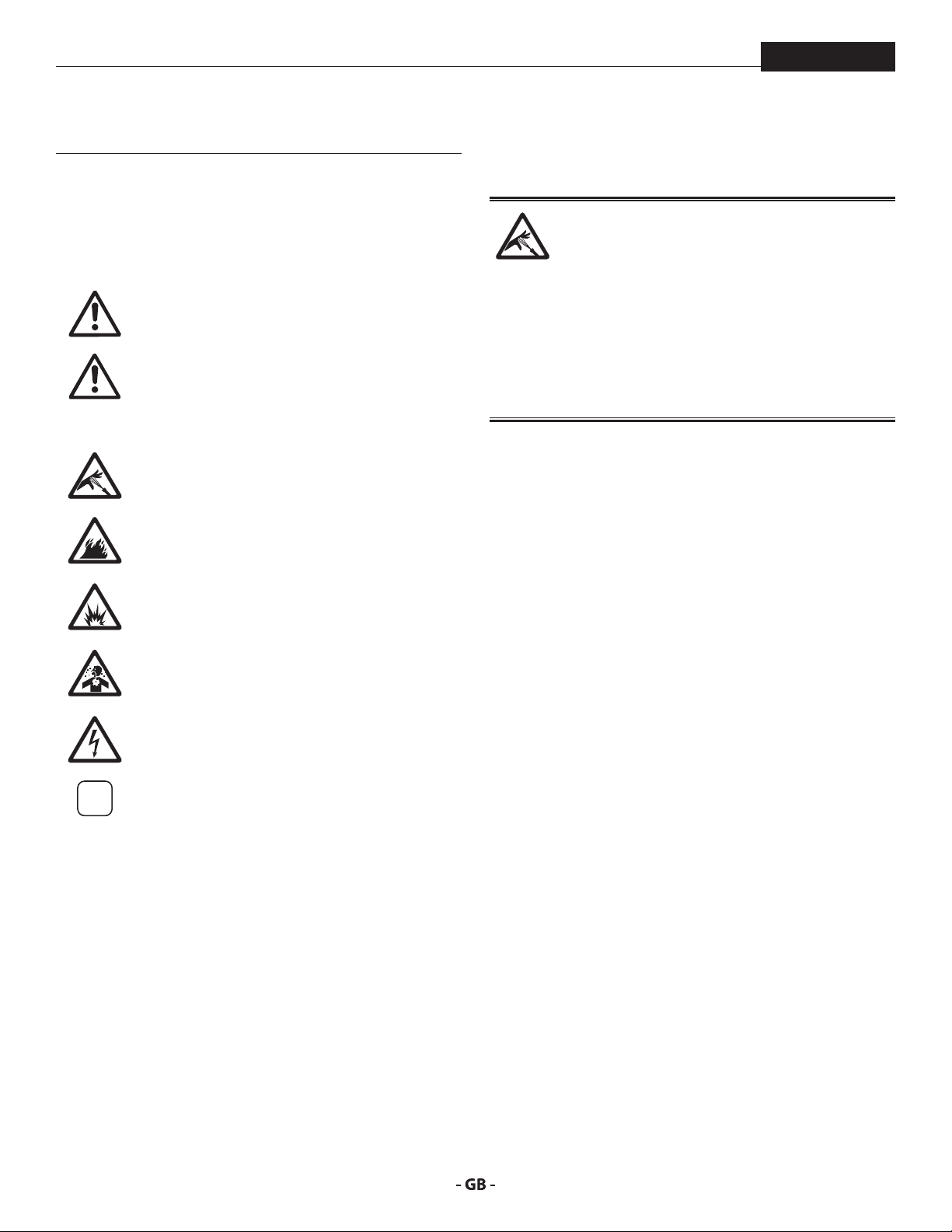
This symbol indicates a potential hazard
that may cause serious injury or loss of life.
Important safety information will follow.
This symbol indicates a potential hazard
to you or to the equipment. Important
tention
information that tells how to prevent
damage to the equipment or how to avoid
causes of minor injuries will follow.
Danger of skin injection
Danger of re from solvent and paint fumes
Danger of explosion from solvent, paint
fumes and incompatible materials
Danger of injury from inhalation of harmful
vapors
Danger of injury from electric shock
Notes give important information which
should be given special attention.
HAZARD: INJECTION INJURY
amputation.
Do not treat a spraying injury as a harmless cut. In
case of injury to the skin through coating materials
about the coating material or solvent used.
PREVENTION:
• NEVER aim the gun at any part of the body.
• NEVER allow any part of the body to touch the uid stream.
DO NOT allow body to touch a leak in the uid hose.
• NEVER put your hand in front of the gun. Gloves will not
provide protection against an injection injury.
• ALWAYS lock the gun trigger, shut the uid pump o and
release all pressure before servicing, cleaning the tip guard,
changing tips, or leaving unattended. Pressure will not be
released by turning o the engine. The PRIME/SPRAY valve
or pressure bleed valve must be turned to their appropriate
positions to relieve system pressure.
• ALWAYS keep tip guard in place while spraying. The tip
guard provides some protection but is mainly a warning
device.
• ALWAYS remove the spray tip before ushing or cleaning
the system.
• NEVER use a spray gun without a working trigger lock and
trigger guard in place.
• All accessories must be rated at or above the maximum
operating pressure range of the sprayer. This includes
spray tips, guns, extensions, and hose.
4
safety precautions
The paint hose can develop leaks from wear,
Flammable vapors, such as solvent and paint
PowrBeast
HAZARD: HIGH PRESSURE HOSE
kinking and abuse. A leak can inject material into
the skin. Inspect the hose before each use.
PREVENTION:
• Avoid sharp bending or kinking of the high-pressure hose.
The smallest bending radius amounts to about 20 cm.
• Do not drive over the high-pressure hose. Protect against
sharp objects and edges.
• Replace any damaged high-pressure hose immediately.
• Never repair damaged high-pressure hoses yourself!
• Electrostatic charging of spray guns and the high-pressure
hose is discharged through the high-pressure hose. For this
reason the electric resistance between the connections of
the high-pressure hose must be equal to or lower than
1M.
• For reasons of function, safety and durability use only
original Titan high-pressure hoses.
• Before each use, check all hoses for cuts, leaks, abrasion
or bulging of cover. Check for damage or movement of
couplings. Immediately replace the hose if any of these
conditions exist. Never repair a paint hose. Replace it with
another earthed high-pressure hose.
• Make sure power cord, air hose and spray hoses are routed
in such a manner to minimize slip, trip and fall hazard.
HAZARD: EXPLOSION OR FIRE
vapors, in work area can ignite or explode.
PREVENTION:
• Use equipment only in well ventilated area. Keep a good
supply of fresh air moving through the area to keep the air
within the spray area free from accumulation of ammable
vapors. Keep pump assembly in well ventilated area. Do
not spray pump assembly.
• Electric models only - Do not use materials with a ashpoint
below 38º C (100º F). Flashpoint is the temperature at which
a uid can produce enough vapors to ignite.
• Gas models only - Do not ll fuel tank while engine is
running or hot; shut o engine and allow to cool. Fuel is
ammable and can ignite or explode if spilled on a hot
surface.
• Eliminate all ignition sources, such as pilot lights, cigarettes,
portable electric lamps and plastic drop cloths (potential
static arc).
• Keep work area free of debris, including solvent, rags and
gasoline.
• Do not plug or unplug power cords, or turn power or light
switches on or o when ammable vapors are present.
• Ground equipment and conductive objects in work
area. Make sure the grounding cable (not equipped) is
connected from the grounding lug to a true earth ground.
• Use only grounded hoses.
• Hold spray gun rmly to the side of a grounded pail when
triggering into pail.
• If there is static sparking or if you feel a shock, stop
operation immediately.
• Know the contents of the paint and solvents being sprayed.
Read all material Safety Data Sheets (SDS) and container
labels provided with the paints and solvents. Follow the
paint and solvent manufacturer’s safety instructions.
• Do not use a paint or solvent containing halogenated
hydrocarbons. Such as chlorine, bleach, mildewcide,
methylene chloride and trichloroethane. They are not
compatible with aluminum. Contact the coating supplier
about compatibility of material with aluminum.
• Keep a re extinguisher in work area.
5
safety precautions
Paints, solvents, and other materials can be
harmful if inhaled or come in contact with body.
Vapors can cause severe nausea, fainting, or
PowrBeast
HAZARD: HAZARDOUS VAPORS
poisoning.
PREVENTION:
• Wear respiratory protection when spraying. Read all
instructions supplied with the mask to be sure it will
provide the necessary protection.
• All local regulations regarding protection against
hazardous vapors must be observed.
• Wear protective eyewear.
• Protective clothing, gloves and possibly skin protection
cream are necessary for the protection of the skin. Observe
the regulations of the manufacturer concerning coating
materials, solvents and cleaning agents in preparation,
processing and cleaning units.
HAZARD: GENERAL
This product can cause severe injury or property
damage.
PREVENTION:
• Follow all appropriate local, state, and national codes
governing ventilation, re prevention, and operation.
• Pulling the trigger causes a recoil force to the hand that is
holding the spray gun. The recoil force of the spray gun
is particularly powerful when the tip has been removed
and high pressure has been set on the airless pump. When
cleaning without a spray tip, set the pressure control knob
to the lowest pressure.
• Use only manufacturer authorized parts. User assumes all
risks and liabilities when using parts that do not meet the
minimum specications and safety devices of the pump
manufacturer.
• ALWAYS follow the material manufacturer’s instructions
for safe handling of paint and solvents.
• Clean up all material and solvent spills immediately to
prevent slip hazard.
• Wear ear protection. This unit can produce noise levels
above 85 dB(A).
• Never leave this equipment unattended. Keep away from
children or anyone not familiar with the operation of airless
equipment.
• Do not spray on windy days.
• The device and all related liquids (i.e. hydraulic oil) must be
disposed of in an environmentally friendly way.
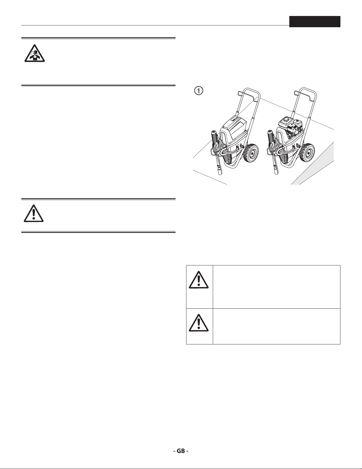
1.3 SETUP ON AN UNEVEN SURFACE
The front end must always point downwards in order to avoid
sliding away.
If possible do not use the unit on an inclined surface since the
unit tends to wander due to the resulting vibrations.
1.4 ELECTRIC SAFETY
Electric models must be grounded/earthed. In the event
of an electrical short circuit, grounding/earthing reduces
the risk of electric shock by providing an escape wire for the
electric current. This product is equipped with a cord having
an grounding/earthing wire with an appropriate grounding/
earthing plug. Connection to the power cord only through a
special feed point, e.g. through an error protection insallation
with INF < 30 mA.
DANGER — Work or repairs at the electrical
equipment may only be carried out by a skilled
electrician. No liability is assumed for incorrect
installation. Switch the unit o. Before all repair
work, unplug the power plug from the outlet.
Danger of short-circuits caused by water
ingressing into the electrical equipment. Never
spray down the unit with high-pressure or highpressure steam cleaners.
1.5 GASOLINE ENGINE SAFETY
1. Gas engines are designed to give safe and dependable
service if operated according to instructions. Read and
understand the engine manufacturer’s Owner’s Manual
before operating the engine. Failure to do so could result
in personal injury or equipment damage.
2. To prevent re hazards and to provide adequate
ventilation, keep the engine at least 1 meter (3 feet) away
from buildings and other equipment during operation. Do
not place ammable objects close to the engine.
6
safety precautions
At
i
i
PowrBeast
3. People who are not operating the device must stay away
from the area of operation due to a possibility of burns from
hot engine components or injury from any equipment the
engine may be used to operate.
4. Know how to stop the engine quickly, and understand the
operation of all controls. Never permit anyone to operate
the engine without proper instructions.
5. Gasoline is extremely ammable and is explosive under
certain conditions.
6. Refuel in a well-ventilated area with the engine stopped.
Do not smoke or allow ames or sparks in the refueling
area or where gasoline is stored.
7. Do not overll the fuel tank. After refueling, make sure the
tank cap is closed properly and securely.
8. Be careful not to spill fuel when refueling. Fuel vapor or
spilled fuel may ignite. If any fuel is spilled, make sure the
area is dry before starting the engine.
9. Never run the engine in an enclosed or conned area.
Exhaust contains poisonous carbon monoxide gas;
exposure may cause loss of consciousness and may lead
to death.
10. The muer becomes very hot during operation and
remains hot for a while after stopping the engine. Be
careful not to touch the muer while it is hot. To avoid
severe burns or re hazards, let the engine cool before
transporting it or storing it indoors.
11. Never ship/transport sprayer with gasoline in the tank.
DO NOT use this equipment to spray water or
acid.
Do not lift by cart handle when loading or
unloading.
tention
Device is very heavy. Three-person lift is required.
1.6 FUELING GAS ENGINE
Gasoline is extremely ammable and is explosive
under certain conditions.
If “spark knock” or “pinging” occurs at a steady
engine speed under normal load, change brands
of gasoline. If spark knock or pinging persists,
consult an authorized dealer of the engine
manufacturer. Failure to do so is considered
misuse, and damage caused by misuse is not
covered by the engine manufacturer’s limited
warranty.
Occasionally you may experience light spark
knock while operating under heavy loads. This
is no cause for concern, it simply means your
engine is operating eciently.
• Unleaded fuel produces fewer engine and spark plug
deposits and extends the life of the exhaust system
components.
• Never use stale or contaminated gasoline or an oil/gasoline
mixture. Avoid getting dirt, dust, or water in the fuel tank.
GASOLINES CONTAINING ALCOHOL
If you decide to use a gasoline containing alcohol (gasohol), be
sure its octane rating is at least as high as that recommended
by the engine manufacturer. There are two types of “gasohol”:
one containing ethanol, and the other containing methanol.
Do not use gasohol that contains more than 10% ethanol. Do
not use gasoline containing methanol (methyl or wood alcohol)
that does not also contain co-solvents and corrosion inhibitors
for methanol. Never use gasoline containing more than 5%
methanol, even if it has co-solvents and corrosion inhibitors.
Fuel system damage or engine performance
problems resulting from the use of fuels that
contain alcohol is not covered under the
warranty. The engine manufacturer cannot
endorse the use of fuels containing methanol
since evidence of their suitability is incomplete
at this time.
Before buying gasoline from an unfamiliar
station, try to nd out if the gasoline contains
alcohol. If it does, conrm the type and
percentage of alcohol used. If you notice any
undesirable operating characteristics while using
a gasoline that contains alcohol, or one that you
think contains alcohol, switch to a gasoline that
you know does not contain alcohol.
FUEL SPECIFICATIONS
Use automotive gasoline that has a pump octane number of 86
or higher, or that has a research octane number of 91 or higher.
Use of a lower octane gasoline can cause persistent “pinging” or
heavy “spark knock” (a metallic rapping noise) which, if severe,
can lead to engine damage.
7
main areas of application
i
i
2 MAIN AREAS OF APPLICATION
PowrBeast
2.1
The main area of application are thick layers of highly viscous
coating material for large areas and a high consumption of
material.
Priming and nal coating of large areas, sealing, impregnation,
construction sanitation, façade protection and renovation, rust
protection and building protection, roof coating, roof sealing,
concrete sanitation, as well as heavy corrosion protection.
EXAMPLES OF OBJECTS TO BE SPRAYED
Large-scale construction sites, cooling towers, bridges, sewage
treatment plants and terraces.
APPLICATION
2.2 COATING MATERIALS
PROCESSIBLE COATING MATERIALS
Diluting lacquers and paints or those containing solvents, twocomponent coating materials, dispersion and latex paints.
No other materials should be used for spraying without Titan‘s
approval.
Pay attention to the Airless quality of the coating
materials to be processed.
VISCOSITY
The unit is able to process coating materials with up to 50.000
/ 65.000 mPas. If highly viscous coating materials cannot be
taken in or the performance of the unit is to low, the paint must
be diluted in accordance with the manufacturer‘s instructions.
Attention: Make sure, when stirring up with
motor-driven agitators that no air bubbles are
stirred in. Air bubbles disturb when spraying and
can, in fact, lead to interruption of operation.
COATING MATERIALS WITH ABRASIVE MATERIALS
These particles have a strong wear and tear eect on valves and
tips, but also on the spray gun. This impairs the durability of
these wearing parts considerably.
TWOCOMPONENT COATING MATERIAL
The appropriate processing time must be adhered to exactly.
Within this time rinse through and clean the unit meticulously
with the appropriate cleaning agents.
FILTERING
Sucient ltering is required for fault-free operation. The unit
is equipped with a suction lter, an insertion lter in the spray
gun and a high pressure lter on the unit. Regular inspection
of these lters for damage or soiling is urgently recommended.
8
description of unit
i
2
PowrBeast
3 DESCRIPTION OF UNIT
3.1
A piston pump takes in the coating material by suction and
conveys it to the tip. Pressed through the tip at a pressure of
up to a maximum of 3300 PSI (228 bar, 22.8 MPa), the coating
material is atomised. This high pressure has the eect of micro
ne atomization of the coating material.
As no air is used in this process, it is described as an AIRLESS
process.
This method of spraying has the advantages of nest
atomization, cloudless operation and a smooth, bubble-free
surface. As well as these, the advantages of the speed of work
and convenience must be mentioned.
AIRLESS PROCESS
3.2 FUNCTIONING OF THE UNIT
The following section contains a brief description of the
technical construction for better understanding of the function
of the unit.
This manual gives information for both electric
motor and gasoline engine PowrBeast models.
TITAN PowrBeast are high-pressure spraying units driven by
either a gasoline engine or electric motor.
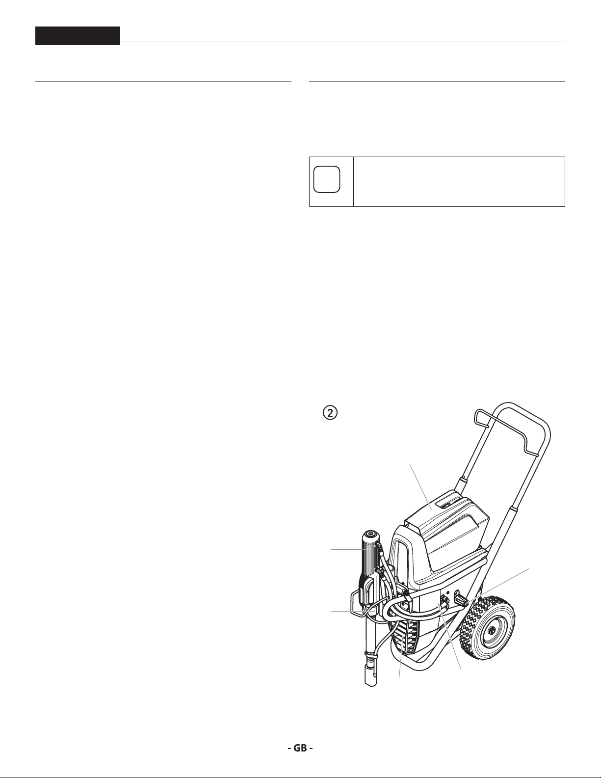
The gasoline engine or electric motor (g. 1, item 1) drives the
hydraulic pump (3) by means of a V-belt which is under the belt
cover (2). Hydraulic oil ows to the hydraulic motor (4) and then
moves the piston up and down in the material feed pump (5).
The inlet valve is opened automatically by the upwards
movement of the piston. The outlet valve is opened when the
piston moves downward.
The coating material ows under high pressure through the
high-pressure hose to the spray gun. When the coating material
exits from the tip it atomizes.
The pressure control valve (6) controls the volume and the
operating pressure of the coating material.
1
4
6
5
3
9
description of unit
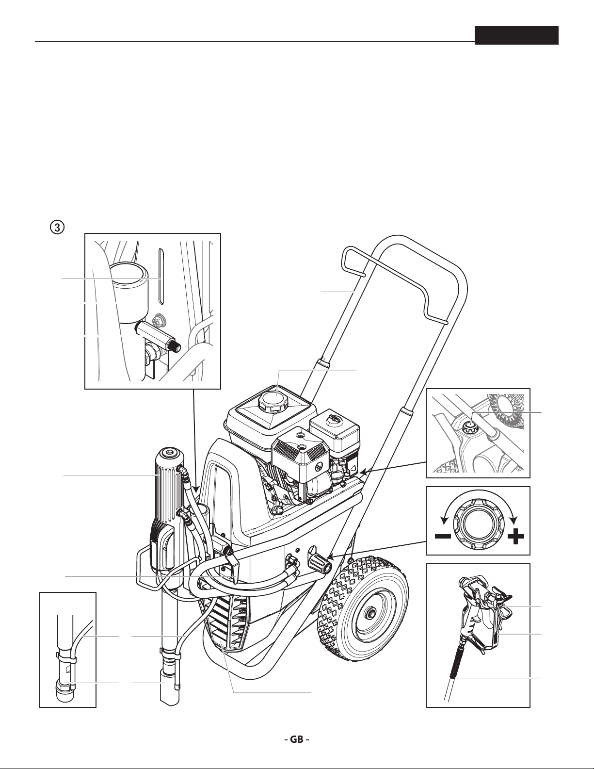
3.3 SYSTEM DIAGRAM GASOLINE POWRBEAST UNITS
PowrBeast
1. Extractable handle
2. Oil cup for separating oil (separating
oil prevents increased wear and tear
of the packings)
3. High-pressure lter
4. High-pressure hose outlet
5. Hydraulic motor
2
3
4
6. Relief valve handle:
Turn left for circulation k
Turn right for spray p
7. Bleed hose
8. Suction tube
9. V-belt under the belt cover
10. Gasoline engine
1
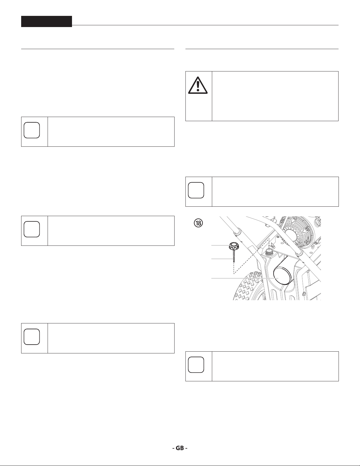
11. Oil measuring stick
12. Pressure control knob
13. Tip guard with airless tip
14. Spray gun
15. High-pressure hose
10
5
6
4700
11
12
13
7
8
14
15
9
10
description of unit
PowrBeast
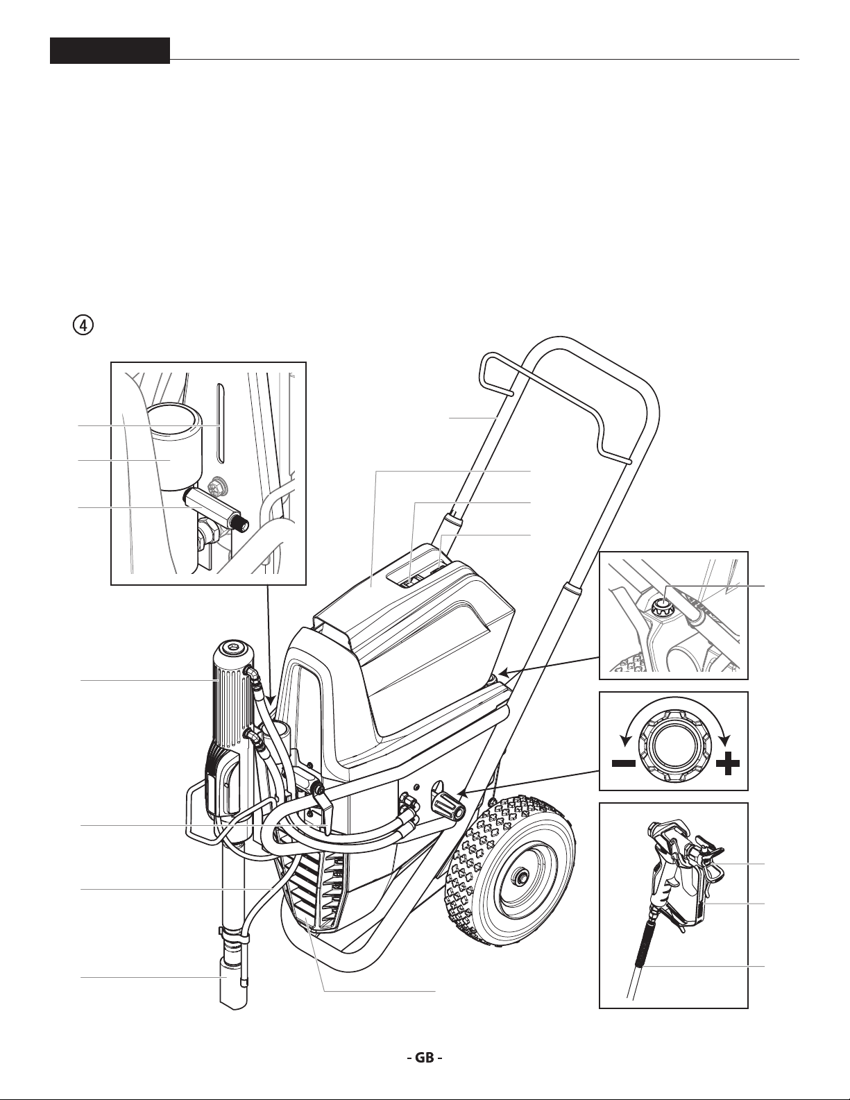
3.4 SYSTEM DIAGRAM ELECTRIC POWRBEAST UNITS
1. Extractable handle
2. Oil cup for separating oil (separating
oil prevents increased wear and tear
of the packings)
3. High-pressure lter
4. High-pressure hose outlet
5. Hydraulic motor
2
3
4
6. Relief valve handle:
Turn left for circulation k
Turn right for spray p
7. Bleed hose
8. Suction tube
9. V-belt under the belt cover
10. Electric motor
1
11. ON/OFF swtich
12. Control lamp that shows unit
operational
13. Oil measuring stick
14. Pressure control knob
15. Tip guard with airless tip
16. Spray gun
17. High-pressure hose
10
11
12
13
5
14
6
15
7
16
17
8
9
11

description of unit
3.5 TECHNICAL DATA
PowrBeast
PowrBeast 4700T
(120V)
Gasoline engine, power
Honda -------- --------
Fuel Capacity
-------- -------- 0.82 US gal (3.1 l) -------- 0.82 US gal (3.1 l) 1.6 US gal (6.06 l)
Voltage
~ 120V, 50/60 Hz ~ 120V, 50/60 Hz -------- ~ 230V, 50/60 Hz -------- --------
Capacity
1.3 kW 1.3 kW -------- 3.1 kW -------- --------
Power Cord
3 x 2.5 mm – 6 m 3 x 2.5 mm – 6 m -------- 3 x 2.5 mm – 6 m -------- --------
Current Protection
15 A 15 A -------- 15 A -------- --------
Max. operating pressure
22.8 MPa (3300 PSI) 22.8 MPa (3300 PSI) 22.8 MPa (3300 PSI) 24.8 MPa (3600 psi) 22.8 MPa (3300 PSI) 22.8 MPa (3300 PSI)
Max. sound pressure level
80 dB (A)* 80 dB (A)* 92 dB (A)* 80 dB (A)* 92 dB (A)* 98 dB (A)*
Max. size of tip with a spray gun
1-gun 0.035” – 0.89 mm 0.035” – 0.89 mm 0.041” – 1.04 mm 0.043” – 1.09 mm 0.047” – 1.19 mm 0.055” – 1.40 mm
2-gun 0.023” – 0.58 mm 0.023” – 0.58 mm 0.029” – 0.73 mm 0.031” – 0.79 mm 0.033” – 0.84 mm 0.039” – 0.99 mm
3-gun 0.019” – 0.48 mm 0.019” – 0.48 mm 0.021” – 0.53 mm 0.023” – 0.58 mm 0.027” – 0.68 mm 0.031” – 0.79 mm
4-gun -------- -------- 0.019” – 0.48 mm 0.021” – 0.53 mm 0.023” – 0.58 mm 0.027” – 0.68 mm
Max. volume ow
1.25 gal (4.75 l)/min 1.25 gal (4.75 l)/min 1.60 gal (6.00 l)/min 1.60 gal (6.00 l)/min 2.00 gal (7.60 l)/min 3.00 gal (11.4 l)/min
Weight
187 lbs (85 kg) 181 lbs (82 kg) 173 lbs (78 kg) 187 lbs (85 kg) 179 lbs (81 kg) 199 lbs (90 kg)
Suction system
submersible standard standard submersible submersible submersible
Max. viscosity
Dimensions L x W x H
Max. temperature of the coating material
Filter insert (standard equipment)
-------- 50 mesh, 18 in 50 mesh, 18 in 0 mesh, 18 in 50 mesh, 18 in 5 mesh, 18 in
Hydraulic oil lling quantity
Max. tire pressure
Special high-pressure hose
DN 10 mm, 15 m (50’
x 3/8”), connection
thread NPSM 1/4
PowrBeast 4700
(120V)
50.000 mPa·s 65.000 mPa·s
PowrBeast 4700
(gas)
163cc, 4.9 Hp, 3.6 kW -------- 196cc, 5.6 Hp, 4.1 kW 270cc, 8.4 Hp, 6.2 kW
43” x 25” x 34” (1090 x 660 x 866 mm)
109ºF (43° C)
5.9 l (1.56 gal) CoolFlo
0.2 MPa (2 bar, 30 PSI)
DN 6 mm, 15 m (50’ x 1/4”), connection thread NPSM 1/4
PowrBeast 7700
(230V)
PowrBeast 7700
(gas)
PowrBeast 9700
(gas)
* Place of measurement: 1 m distance from unit and 1.60 m above reverberant oor, 120 bar (12 MPa) operating pressure.
12
description of unit / operation
i
PowrBeast
4 OPERATION
OPERATING TEMPERATURE
This equipment will operate correctly in its intended ambient,
at a minimum between +50ºF (10°C) and 104ºF (+40°C).
RELATIVE HUMIDITY
The equipment will operate correctly within an environment
at 50% RH, 104ºF (+40°C). Higher RH may be allowed at lower
temperatures.
Measures shall be taken by the Purchaser to avoid the harmful
eects of occasional condensation.
ALTITUDE
This equipment will operate correctly up to 2100 m above
mean sea level.
TRANSPORTATION AND STORAGE
This equipment will withstand, or has been protected against,
transportation and storage temperatures of -13ºF (-25°C) to
131ºF (+55°C) and for short periods up to 150ºF (+70°C).
It has been packaged to prevent damage from the eects of
normal humidity, vibration and shock.
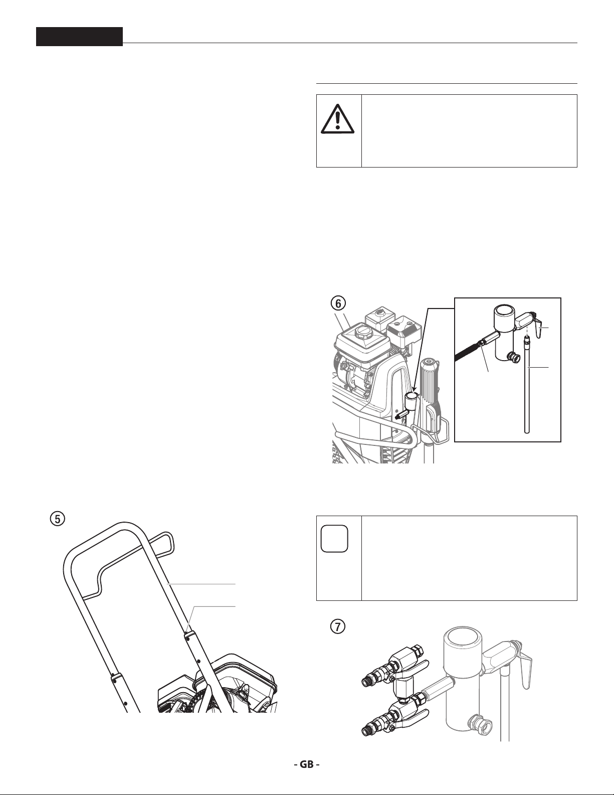
4.1 SETUP
1. Make sure the bleed hose (Fig. 6, item 1) is threaded into
2. Attach a minimum of 50’ (15 m) of nylon airless spray hose
This equipment produces a uid stream at
extremely high pressure. Read and understand
the warnings in the Safety Precautions section
at the front of this manual before operating this
equipment.
the bleed valve (2). It has factory installed PTFE tape on
the tting and should be tightened wrench tight.
(3) to the sprayer. Do not use PTFE tape or thread sealant
on the spray hose connection.
2
3.6 TRANSPORTATION
TRANSPORTATION IN VEHICLE
Secure the unit with a suitable fastening.
PUSHING OR PULLING THE UNIT
Pull out the handle (Fig. 5, Item 1) until it will come no further.
Insert the handle – push the buttons (2) on the cart, and then
push in the handle.
1
2
1
3
3. Attach an airless spray gun to the spray hose. Do not
attach the tip to the spray gun yet. Remove the tip if it is
already attached.
For multiple gun operation, connect a multiple
gun manifold to the single gun outlet. Connect
a hose and gun to each outlet. Make sure
the second gun outlet remains plugged. See
“Technical Data”, Section 3.5 to determine
number of guns and maximum spray tip sizes.
13
operation
At
At
PowrBeast
4. Fill the oil cup 1/2 full with Piston Lube (P/N 314-480). This
extends packing life.
Piston Lube prevents increased wear and tear to
the packings.
tention
5. Check the hydraulic uid level daily before starting the
sprayer. The hydraulic uid level should be touching
the bottom of the dipstick. Refer to the Maintenance
section of this manual for hydraulic system maintenance
instructions.
Proper grounding/earthing is important. The
passage of some materials through the nylon
uid hose will build up a static electric charge,
which if discharged, could ignite solvent vapors
present and create an explosion.
9. Strain all paints with a nylon strainer to ensure trouble
free operation and freedom from frequent cleaning of the
suction lter and gun lter.
10. Make sure the spray area is well ventilated to prevent
hazardous operation with volatile solvents or exhaust
fumes.
If lacquer or other ammable materials are to be
sprayed, ALWAYS locate the sprayer outside the
immediate spraying area. Failure to do so may
cause an explosion.
11. Locate the sprayer outside the immediate spraying area to
avoid clogged air intake of the engine with overspray.
Use of Titan’s Coolo™ Hydraulic Fluid (P/N 430-
361) is mandatory in the hydraulic system. Do
tention
6. For gas models, check the engine oil level daily before
7. For electric models, use a 15 amp service outlet. Always
8. Make sure the sprayer is grounded/earthed. All sprayers are
not use any other hydraulic uid. Use of any
other hydraulic uid may seriously damage the
hydraulic system and will void the warranty.
starting the sprayer. The gasoline engine oil level is
determined by the engine manufacturer. Refer to the
engine manufacturer’s service manual supplied with this
sprayer.
locate the electric model within 10 to 15 feet of the service
outlet. Use a short electric cable and a long paint hose.
Any extension cord will create some voltage drop. If an
extension cord is necessary, use only a grounded 3-wire
12-gauge extension cord.
equipped with a grounding/earthing lug. A grounding/
earthing cable should be used to connect the sprayer to a
true earth ground. Check your local electrical regulations
for detailed grounding/earthing instructions.
14
operation
i
i
i
At
PowrBeast
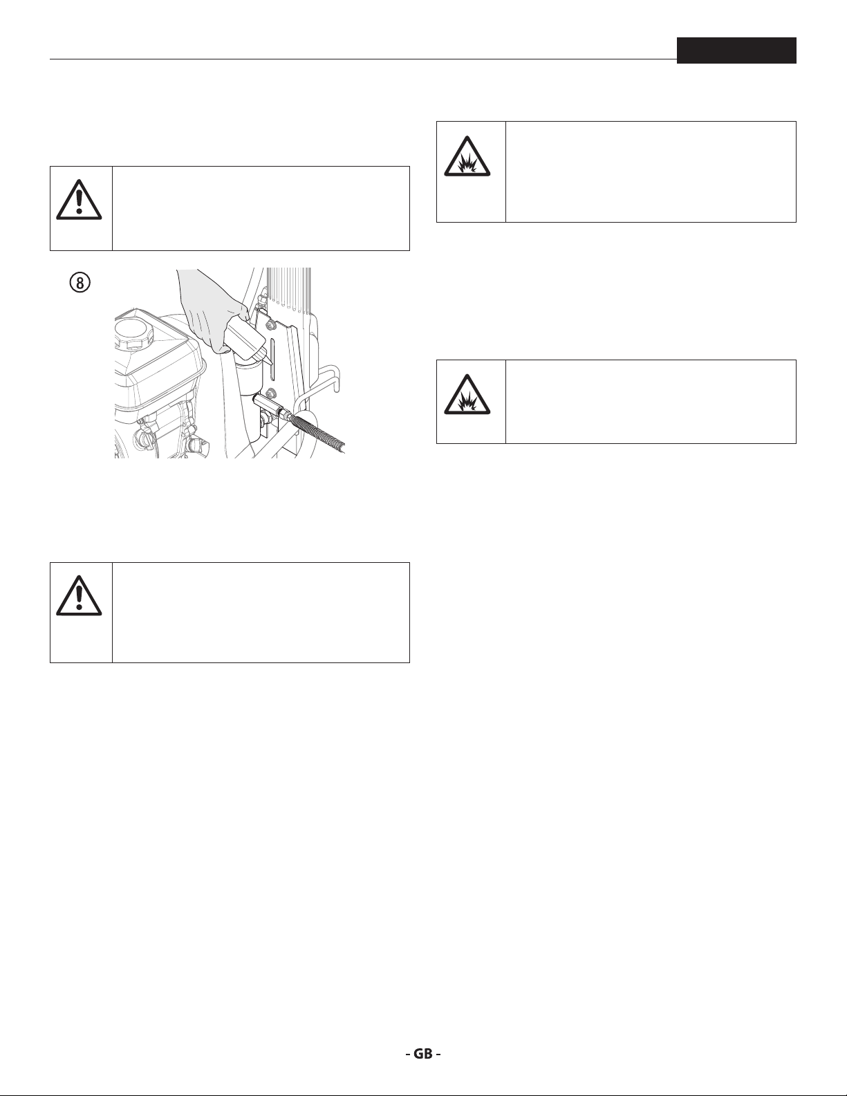
4.2 STARTING THE ENGINE GAS MODELS
Follow these instructions whenever prompted in
this manual to start the engine.
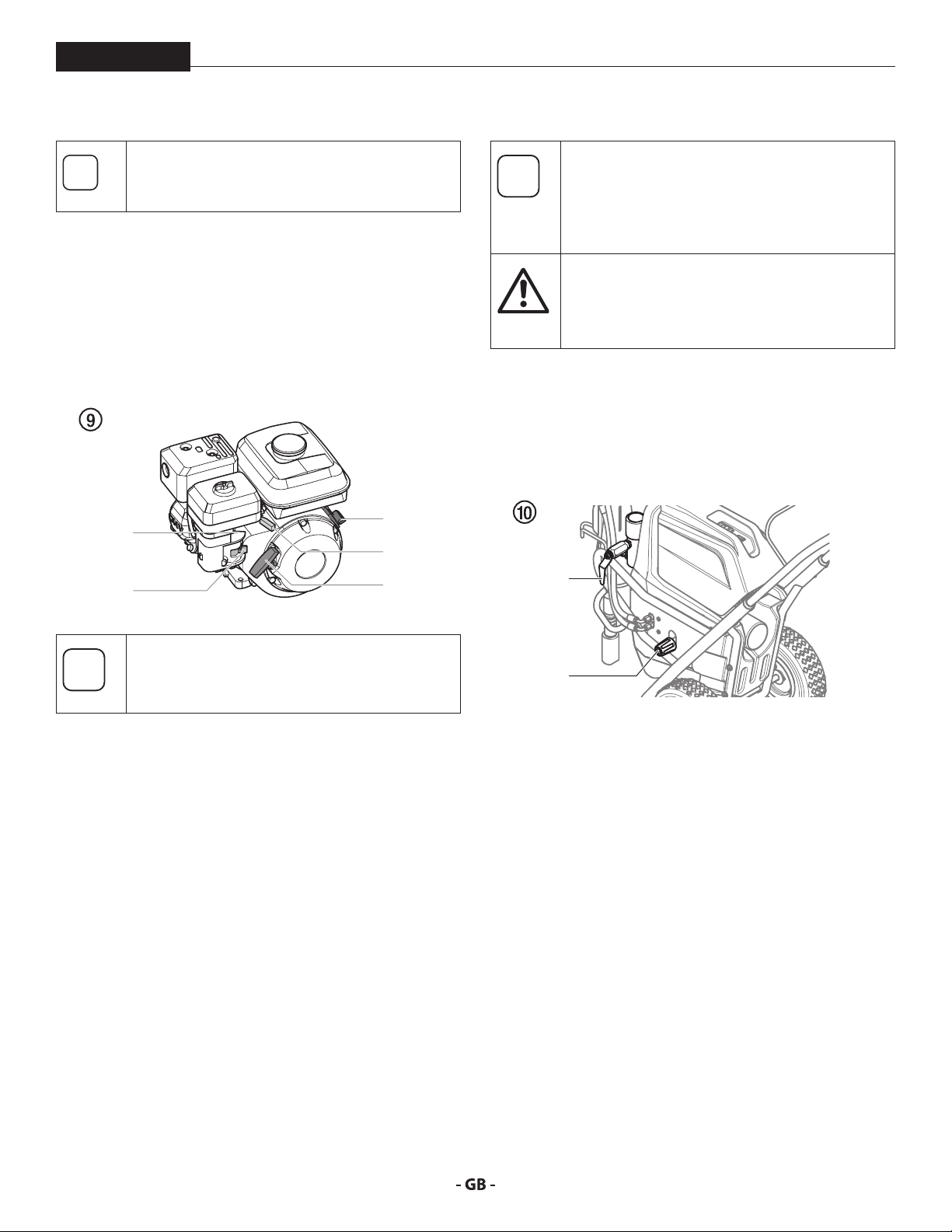
1. Move the fuel valve lever (Fig. 9, item 2) to the open
position.
2. Move the throttle lever (3) to its middle point.
3. Move the choke lever (4) to the closed position for a cold
engine or to the open position for a warm engine.
4. Turn the engine switch (1) to the ON position.
5. Pull the starter rope (5) briskly until the engine starts.
4
2
1
3
5
4.3 PREPARING A NEW SPRAYER
If this unit is new, it is shipped with test uid in
the uid section to prevent corrosion during
shipment and storage. This uid must be
thoroughly cleaned out of the system with
mineral spirits before you begin spraying.
Always keep the trigger lock on the spray gun in
the locked position while preparing the system.
tention
1. Place the siphon tube into a container of mineral spirits.
2. Place the bleed hose into a metal waste container.
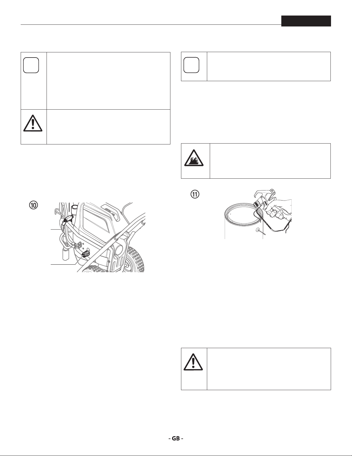
3. Turn the pressure control knob fully counterclockwise to
4. Open the bleed valve (2) by turning it fully counterclockwise.
Refer to the spray gun instruction manual for
trigger lock instructions.
its lowest pressure setting (Fig. 10, item 1).
2
If choke lever (4) was moved to closed position to
start the engine, it must be opened again once
the engine is running.
1
5. Start the engine or turn on the electric motor:
a. To start the gas engine, follow the steps in section 4.2
b. To start the electric motor, push and hold the ON/OFF
switch in the ON position until the electric motor is at full
speed, then release the switch.
6. Turn the pressure control knob (g. 10, item 1) clockwise
approximately 1/3 of the way to increase pressure until
the sprayer cycles evenly and solvent ows freely from the
bleed hose.
7. Allow the sprayer to run for 15–30 seconds to ush the
test uid out through the bleed hose and into the waste
container.
8. Turn o the sprayer.
a. To turn o the gas engine,
• set the pressure to minimum by turning the pressure
control knob fully counterclockwise,
• move the throttle lever to the slow position, and
• turn the engine switch to the OFF position.
b. To turn o the electric motor,
• set the pressure to minimum by turning the pressure
control knob fully counterclockwise,
• move the ON/OFF switch to the OFF position.
15
operation
i
At
i
4.4 PREPARING TO PAINT
PowrBeast
Before painting, it is important to make sure that
the uid in the system is compatible with the
paint that is going to be used.
Incompatible uids and paint may cause the
valves to become stuck closed, which would
require disassembly and cleaning of the sprayer’s
uid section.
Always keep the trigger lock on the spray gun in
the locked position while preparing the system.
tention
1. Place the siphon tube into a container of mineral spirits.
2. Place the bleed hose into a metal waste container.
3. Turn the pressure control knob fully counterclockwise to
4. Open the bleed valve (2) by turning it fully counterclockwise.
Refer to the spray gun instruction manual for
trigger lock instructions.
its lowest pressure setting (Fig. 10, item 1).
Make sure that the spray gun does not have a tip
or tip guard installed.
9. Close the bleed valve by turning it fully clockwise.
10. Start the engine or turn on the electric motor.
11. Turn the pressure control knob clockwise approximately
1/3 of the way down to increase pressure.
12. Unlock the gun by turning the gun trigger lock to the
unlocked position.
Ground/Earth the gun by holding it against
the edge of the metal container while ushing.
Failure to do so may lead to a static electric
discharge, which may cause a re.
2
13. Trigger the gun into the metal waste container until the
old solvent is gone and fresh solvent is coming out of the
1
5. Start the engine or turn on the electric motor:
a. To start the gas engine, follow the steps in section 4.2
b. To start the electric motor, push and hold the ON/OFF
switch in the ON position until the electric motor is at full
speed, then release the switch.
6. Turn the pressure control knob (Fig. 10, item 1) clockwise
approximately 1/3 of the way to increase pressure until
the sprayer cycles evenly and solvent ows freely from the
bleed hose.
7. Allow the sprayer to run for 15–30 seconds to ush the
test uid out through the bleed hose and into the waste
container.
8. Turn o the sprayer.
a. To turn o the gas engine,
• set the pressure to minimum by turning the pressure
control knob fully counterclockwise,
• move the throttle lever to the slow position, and
• turn the engine switch to the OFF position.
b. To turn o the electric motor,
• set the pressure to minimum by turning the pressure
control knob fully counterclockwise,
• move the ON/OFF switch to the OFF position.
gun.
14. Lock the gun by turning the gun trigger lock to the locked
position (refer to spray gun manual).
15. Set down the gun and increase the pressure by turning
the pressure control knob slowly clockwise to its highest
setting.
16. Check the entire system for leaks. If leaks occur, turn the
sprayer o and follow the “Pressure Relief Procedure” in
this manual before tightening any ttings or hoses.
17. Follow the “Pressure Relief Procedure” (section 4.6) in this
manual before changing from solvent to paint.
Be sure to follow the Pressure Relief Procedure
when shutting the unit down for any purpose,
including servicing or adjusting any part of the
spray system, changing or cleaning spray nozzles,
or preparing for cleanup.
16
operation
i
PowrBeast
4.5 PAINTING
1. Place the siphon hose into a container of paint.
2. Place the bleed hose into a metal waste container.
3. Turn the pressure control knob fully counterclockwise to
its lowest pressure setting (Fig. 10, item 1).
4. Open the bleed valve (2) by turning it fully counterclockwise.
5. Start the engine or turn on the electric motor:
a. To start the gas engine, follow the steps in section 4.2
b. To start the electric motor, push and hold the ON/OFF
switch in the ON position until the electric motor is at full
speed, then release the switch.
6. Turn the pressure control knob (Fig. 10, item 1) clockwise
approximately 1/3 of the way down to increase pressure
until the sprayer cycles evenly and solvent ows freely
from the bleed hose.
7. Turn o the sprayer.
a. To turn o the gas engine,
• set the pressure to minimum by turning the pressure
control knob fully counterclockwise,
• move the throttle lever to the slow position, and
• turn the engine switch to the OFF position.
b. To turn o the electric motor,
• set the pressure to minimum by turning the pressure
control knob fully counterclockwise,
• move the ON/OFF switch to the OFF position.
8. Remove the bleed hose from the waste container and
place it into the container of paint.
9. Close the bleed valve by turning it fully clockwise.
10. Start the engine or turn on the electric motor.
11. Turn the pressure control knob clockwise approximately
1/3 of the way down to increase pressure.
12. Unlock the gun by turning the gun trigger lock to the
unlocked position.
Ground/Earth the gun by holding it against
the edge of the metal container while ushing.
Failure to do so may lead to a static electric
discharge, which may cause a re.
13. Trigger the gun into the metal waste container until all
air and solvent is ushed from the spray hose and paint is
owing freely from the gun.
14. Lock the gun by turning the gun trigger lock to the locked
position.
15. Turn o the sprayer.
16. Attach tip guard and tip to the gun as instructed by the tip
guard or tip manuals.
17. Start the engine or turn on the electric motor.
18. Increase the pressure by turning the pressure control knob
slowly clockwise and test the spray pattern on a piece of
cardboard. Adjust the pressure control knob until the
spray from the gun is completely atomized.
4.6 PRESSURE RELIEF PROCEDURE
1. Lock the spray gun by turning the gun trigger lock to the
locked position.
2. Turn o the sprayer.
a. To turn o the gas engine,
• set the pressure to minimum by turning the pressure
• move the throttle lever to the slow position, and
• turn the engine switch to the OFF position.
b. To turn o the electric motor,
• set the pressure to minimum by turning the pressure
• move the ON/OFF switch to the OFF position.
3. Unlock the gun by turning the gun trigger lock to the
unlocked position (refer to spray gun manual).
4. Hold the metal part of the gun rmly to the side of a metal
waste container to ground/earth the gun and avoid a build
up of static electricity.
5. Trigger the gun to remove any pressure that may still be
in the hose.
6. Lock the gun by turning the gun trigger lock to the locked
position (refer to spray gun manual).
7. Place the bleed hose into the metal waste container.
8. Open the bleed valve by turning it fully counterclockwise.
POSSIBLE INJECTION HAZARD. Do not spray
without the tip guard in place. Never trigger the
gun unless the tip is in either the spray or the
unclog position. Always engage the gun trigger
lock before removing, replacing or cleaning tip.
Turning the pressure up higher than needed to
atomize the paint will cause premature tip wear
and additional overspray.
Be sure to follow the Pressure Relief Procedure
when shutting the unit down for any purpose,
including servicing or adjusting any part of the
spray system, changing or cleaning spray nozzles,
or preparing for cleanup.
control knob fully counterclockwise,
control knob fully counterclockwise,
17
spraying
i
i
5 SPRAYING
PowrBeast
Injection hazard. Do not spray without the tip
guard in place. NEVER trigger the gun unless
the tip is completely turned to either the spray
or the unclog position. ALWAYS engage the
gun trigger lock before removing, replacing or
cleaning tip.
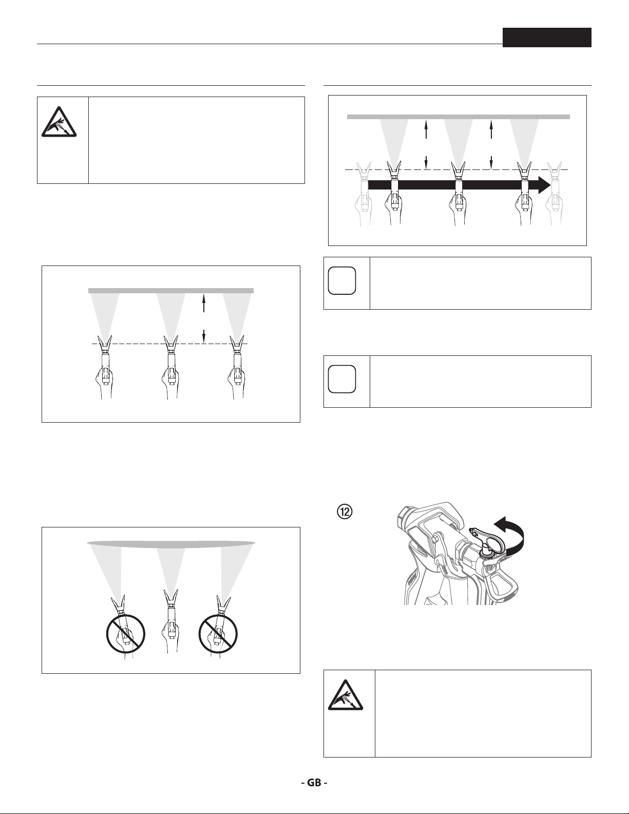
A) The key to a good paint job is an even coating over the
entire surface. Keep your arm moving at a constant speed
and keep the spray gun at a constant distance from the
surface. The best spraying distance is 10-12 inches (25 to
30 cm) between the spray tip and the surface.
A
25 - 30 cm
C
25 - 30 cm25 - 30 cm
If very sharp edges result or if there are streaks in
the spray jet – increase the operating pressure or
dilute the coating material.
5.1 CLEANING A CLOGGED TIP
If the spray pattern becomes distorted or stops
completely while pulling the trigger, perform the
steps below.
B) Keep the spray gun at right angles to the surface. This
means moving your entire arm back and forth rather than
just exing your wrist.
Keep the spray gun perpendicular to the surface,
otherwise one end of the pattern will be thicker than the
other.
B
C) Trigger gun after starting the stroke. Release the trigger
before ending the stroke. The spray gun should be
moving when the trigger is pulled and released. Overlap
each stroke by about 30%. This will ensure an even
coating.
1. Turn the relief valve to PRIME (k circulation).
2. If the tip clogs, rotate the tip handle 180° until the arrow on
the handle is facing the opposite of the spray direction and
the handle clicks in the reverse position (Fig. 12).
3. Turn the relief valve to SPRAY (p spray).
4. Trigger the gun once so that the pressure can blow the
clog out. NEVER use the tip in the reverse position for
more than ONE trigger pull at a time. This procedure can
be repeated until the tip is free of clogging.
The ow from the spray tip is at very high
pressure. Contact with any body part may be
dangerous. Do not place nger on gun outlet.
Do not point the gun at any person. Never
operate the spray gun without the proper tip
guard.
18
spraying
i
i
At
i
i
i
i
i
PowrBeast
5.2 INTERRUPTION OF WORK
Follow these steps if stopping work for up to 20
hours. Only follow these steps if you used latex or water-based spray materials.
If you are just simply swapping out material
containers, turn the pressure control knob fully
counterclockwise to minimum prior to changing
the material container.
Turn pressure control knob clockwise to previous
position when ready to resume spraying.
1. Follow the “Pressure Relief Procedure” found in the
Operation section of this manual, section 4.6.
2. Place the spray gun in a plastic bag, or drop it into a bucket
of water.
3. Leave the suction tube and return hose immersed in
the coating material or immerse it into a corresponding
cleaning agent.
4. Cover the coating material with plastic and place unit in a
cool, shaded spot to keep material from drying out.
If fast-drying or two-component coating material
is used, ensure that the unit is rinsed with a
tention
suitable cleaning agent within the processing
time.
When ready to being spraying again, remove the
plastic from the material container and restart
the sprayer by following the steps in section 4.5.
5.3 HANDLING THE HIGHPRESSURE HOSE
The unit is equipped with a high-pressure hose
specially suited for airless pumps.
Danger of injury through leaking high-pressure
hose. Replace any damaged high-pressure hose
immediately.
Never repair damaged high-pressure hoses
yourself!
The high-pressure hose is to be handled with care. Avoid sharp
bends and folds: the smallest bending radius is about 8” (20 cm).
Do not drive over the high-pressure hose. Protect against sharp
objects and edges.
Never pull on the high-pressure hose to move the device.
Make sure that the high-pressure hose cannot twist. This can
be avoided by using a Titan spray gun with a swivel joint and
hose system.
When using the high-pressure hose while
working on scaolding, it is best to always guide
the hose along the outside of the scaolding.
The risk of damage rises with the age of the
high-pressure hose. Titan recommends replacing
high-pressure hoses after 6 years.
Use only Titan original-high-pressure hoses
in order to ensure functionality, safety and
durability.
19
cleanup
At
At
i
At
Attention
6 CLEANUP
The sprayer, hose, and gun should be cleaned
thoroughly after daily use. Failure to do so
tention
permits material to build up, seriously aecting
the performance of the unit.
PowrBeast
9. Switch the unit OFF (turn the engine switch OFF).
10. Close the bleed valve by rotating the bleed valve handle
fully clockwise.
11. Start the engine or turn on the electric motor.
Always spray at minimum pressure with the gun
nozzle tip removed when using mineral spirits
or any other solvent to clean the sprayer, hose,
or gun. Static electricity buildup may result in a
re or explosion in the presence of ammable
vapors.
6.1 SPECIAL CLEANUP INSTRUCTIONS FOR USE
WITH FLAMMABLE SOLVENTS
• Always ush spray gun preferably outside and at least one
hose length from spray pump.
• If collecting ushed solvents in a one gallon metal
container, place it into an empty ve gallon container, then
ush solvents.
• Area must be free of ammable vapors.
• Follow all cleanup instructions.
6.2 CLEANING THE SPRAYER
1. Follow the “Pressure Relief Procedure” found in the
Operation section of this manual, section 4.6.
2. Remove the gun tip and tip guard and clean with a brush
using the appropriate solvent.
3. Place the siphon tube into a container of the appropriate
solvent.
Earth the gun by holding it against the edge
of the metal container while ushing. Failure
to do so may lead to a static electric discharge,
which may cause a re.
12. Trigger the gun into the metal waste container until the
paint is ushed out of the hose and solvent is coming out
of the gun.
13. Continue to trigger the spray gun into the waste container
until the solvent coming out of the gun is clean.
For long-term or cold weather storage, pump
mineral sprits through the entire system.
14. Follow the “Pressure Relief Procedure” found in the
Operation section of this manual.
15. Store the sprayer in a clean, dry area.
Do not store the sprayer under pressure.
tention
6.3 CLEANING THE OUTSIDE OF THE UNIT
Use only compatible solvents when cleaning
out oil based enamels, lacquers, coal tar, and
tention
4. Place the bleed hose into a metal waste container.
5. Set the pressure to minimum by turning the pressure
6. Open the bleed valve by rotating the bleed valve handle
7. Start the engine or turn on the electric motor.
8. Allow the solvent to circulate through the sprayer and
epoxies. Check with the uid manufacturer for
the recommended solvent.
control knob fully counterclockwise.
fully counterclockwise.
ush the paint out of the bleed hose into the metal waste
container.
20
Electric models - Make sure the power cord is
unplugged to prevent electric shock.
Danger of short circult through penetrating
water!
Never spray down the unit with high-pressure
water or high-pressure steam cleaners.
Do not put the high-pressure hose into solvents.
Use only a wet cloth to wipe down the outside of
the hose.
Wipe down unit externally with a cloth which has been
immersed in a suitable cleaning agent.
cleanup
i
i
PowrBeast
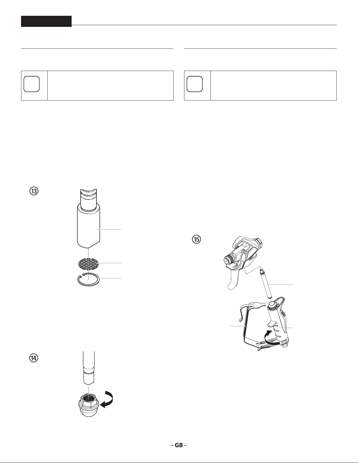
6.4 CLEANING THE FILTER SCREEN
A clean lter screen always guarantees maximum
feed quantity, constant spraying pressure and
problem-free functioning of the unit.
SUBMERSIBLE SUCTION SYSTEM
1. The lter screen will clog and must be cleaned at least
once a day.
2. Remove the retaining ring (Fig. 13, item 1) from the foot
valve housing (2).
3. Remove the inlet screen (3) from the foot valve housing
(2).
4. Clean thoroughly with the appropriate solvent.
2
6.5 CLEANING AIRLESS SPRAY GUN
Clean the spray gun after each use.
1. Rinse airless spray gun with an appropriate cleaning agent.
2. Clean tip thoroughly with appropriate cleaning agent so
that no coating material residue remains.
3. Thoroughly clean the outside of the airless spray gun.
INTAKE FILTER IN AIRLESS SPRAY GUN FIG. 15
1. Unclip the top of the trigger guard (1) from the gun head.
2. Using the bottom of the trigger guard as a wrench, loosen
and remove the handle assembly (2) from the gun head.
3. Pull the old lter (3) out of the gun head. Clean or replace.
4. Slide the new lter, tapered end rst, into the gun head.
5. Thread the handle assembly into the gun head. Tighten
with the trigger wrench.
6. Snap the trigger guard back onto the gun head.
3
1
STANDARD SUCTION SYSTEM
1. Screw o the lter (Fig. 14) from suction tube.
2. Clean or replace the lter.
Carry out cleaning with a hard brush and an appropriate
cleaning agent.
3
1
2
21
maintenance
i
i
i
7 MAINTENANCE
PowrBeast
Before proceeding, follow the Pressure Relief
Procedure outlined previously in this manual.
Additionally, follow all other warnings to reduce
the risk of an injection injury, injury from moving
parts or electric shock. Always unplug the sprayer
before servicing!
7.1 DAILY MAINTENANCE
Two daily procedures are required for routine operator
maintenance on this sprayer:
A. Lubricating the upper packings (section 7.2).
B. Cleaning the lter screen (section 6.4).
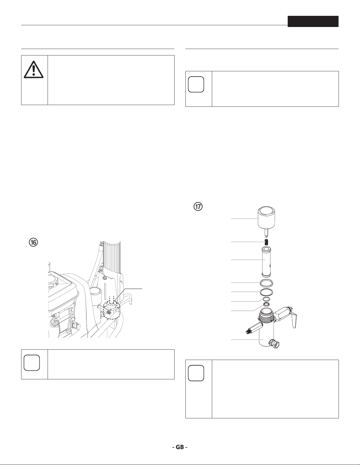
7.2 LUBRICATING THE UPPER PACKINGS
1. Clean out the paint that has seeped past the upper
packings into the packing oil reservoir (g. 16, item 1)
above the uid section.
2. Fill the packing oil reservoir 1/2 full with Piston Lube (P/N
314-480) supplied by the factory. This will extend packing
life.
7.3 MAINTAINING THE FILTER ASSEMBLY
Clean the lter regularly. Dirty or clogged lters
can greatly reduce ltering ability and cause
a number of system problems including poor
spray patterns, clogged spray tips, etc.
CLEANING FIG. 17
To clean the lter, perform the following procedure.
1. Follow the “Pressure Relief Procedure” found in the
Operation section of this manual.
2. Remove the lter cap assembly (1) and spring (2).
3. Pull the lter element with ball straight (3) out of the lter
body (4).
4. Clean inside the lter body, lter element with ball, and
lter cap assembly using the appropriate solvent.
1
1
Do not over-ll the reservoir so that it overows
and drips into the paint.
2
3
7
8
5
6
4
Use care in handling parts as dirt, debris,
scratches, or nicks may prevent o-rings or gaskets
from sealing.
This lter element lters from the inside out. Be
sure to clean the lter element thoroughly on the
inside. Soak in solvent to loosen hardened paint
or replace.
22
maintenance
i
i
i
At
i
i
PowrBeast
INSPECTION FIG. 17
Inspect all parts of the lter assembly before reassembly.
1. Inspect the ball inside the lter element. If the ball has
pressure cuts or scratches, replace the lter element.
a. If the ball is cut, remove the PTFE o-ring (5) using an
o-ring pick and remove the carbide seat (6).
b. Check the seat for nicks or grooves. If the seat is
damaged, replace.
Removal of the PTFE o-ring will damage the
o-ring and require replacement.
2. Remove the spring (2) from the spring guide on the lter
cap.
a. Measure the length of the spring uncompressed. If it
measures less than 3/4” from end to end, replace.
b. Push the spring back onto the spring guide until it
“snaps” back into position.
3. Inspect the two PTFE gaskets (7,8) and the PTFE o-ring (5)
for deformity, nicks, or cuts. Replace, if needed.
The PTFE gaskets, PTFE o-ring, and spring are
packaged in Filter Service Kit P/N 930-050.
7.4 MAINTAINING THE HYDRAULIC SYSTEM
Use of Titan’s Coolo™ Hydraulic Fluid is
mandatory in the PowrTwin Plus DI hydraulic
tention
1. Check the hydraulic uid daily. The hydraulic uid level
system. Do not use any other hydraulic uid.
Use of any other hydraulic uid may seriously
damage the hydraulic system and will void the
warranty.
should be touching the bottom of the dipstick (1). If it is
dry, add only Titan Coolo™ Hydraulic Fluid (P/N 430-361).
Never add or change hydraulic uid except in a clean,
dust-free area. Contamination of the hydraulic uid will
shorten hydraulic pump life and may void warranty.
Make sure the unit is on a at, level surface when
checking the hydraulic uid level.
REASSEMBLY FIG. 17
After cleaning and inspecting all parts, reassemble the lter.
1. Place the carbide seat (6) into the lter body (4). Make sure
the beveled side of the seat is facing up.
2. Place the PTFE o-ring (5) into the groove on the outer
diameter of the carbide seat (6).
3. Place the lter element with ball (3) into the lter body (4).
The top and bottom of the lter element with
ball are identical.
4. Push the spring (2) back onto the spring guide of the lter
cap (1) until it “snaps” back into position, if not already
done.
5. Place the thin PTFE gasket (8) onto the step at the top of
the lter body (4).
6. Place the thick PTFE gasket (7) onto the top of the thin
gasket (8).
7. Tighten the lter cap assembly (1) onto the lter body (4).
2
1
3
2. Change the hydraulic uid every twelve months. Drain the
old uid from the tank and ll with 6.25 quarts of hydraulic
uid. Start the sprayer at just enough pressure to operate
the uid section. Run the sprayer at this low pressure for at
least 5 minutes. This removes air from the system. Check
the uid level after this procedure. Do not over-ll.
When replacing the hydraulic lter (3) during a
uid change, it may be necessary to add up to
one additional quart of hydraulic uid.
3. The hydraulic system has an external, replaceable hydraulic
lter. Change the lter every twelve months.
4. The hydraulic pump should not be serviced in the eld.
If service on the hydraulic pump is required, it must be
returned to an authorized Titan Service Center.
23

maintenance
At
i
PowrBeast
7.5 MAINTAINING THE FLUID SECTION
If the sprayer is going to be out of service for an extended period
of time, it is recommended that following cleanup, a kerosene
and oil mixture be introduced as a preservative. Packings may
tend to dry out from lack of use. This is particularly true of the
upper packing set for which upper packing lubricant Piston
Lube (P/N 314-480) is recommended in normal usage.
If the sprayer has been out of service for an extended period
of time, it may be necessary to prime the pump with solvent.
It is extremely important that the threads on the siphon hose
coupling are properly sealed. Any air leakage will produce
erratic operation of the sprayer and may damage the system.
The up and the down strokes should be approximately equal
in time (one should not be faster than the other). A fast up or
down stroke may indicate air in the system or malfunctioning
valve or seats (see the Troubleshooting section).
7.6 HIGHPRESSURE HOSE
Inspect the high-pressure hose visually for any notches or
bulges, in particular at the transition in the ttings. It must be
possible to turn the union nuts freely. A conductivity of less
than 1 MΩ must exist across the entire length.
Have all the electric tests carried by an Authorized
Titan Service Center.
tention
The risk of damage rises with the age of the highpressure hose.
Titan recommends replacing high-pressure
hoses after 6 years.
24
maintenance
PowrBeast
7.7 BASIC ENGINE MAINTENANCE GAS ENGINE
• For detailed engine maintenance and technical
specications refer to the separate gasoline engine manual.
• All service to the engine should be performed by a dealer
authorized by the engine manufacturer.
• Use a premium quality motor oil. 10W30 is recommended
for general all temperature use. Other viscosities may be
required in other climates.
• Use only a (NGK) BP6ES or BPR6E spark plug. Gap the
plug to 0.028 to 0.031 In. (0.7 to 0.8 mm) Always use a
spark plug wrench.
DAILY
1. Check engine oil level, and ll as necessary.
2. Check gasoline level, and ll as necessary.
Always follow the fueling procedure outlined
earlier in this manual.
FIRST 20 HOURS
• Change engine oil.
ENGINE OPERATION AND SERVICE
• Clean and oil air lter pad on gasoline engine every 25
hours or once weekly. Do not permit the air intake screen
around the y wheel of the gas engine to load up with paint
or trash. Clean it regularly. The service life and eciency
of the gas engine model depends upon keeping the
gasoline engine running properly. Change the oil in the
engine every 100 hours. Failure to observe this may result
in engine overheating. Consult the engine manufacturer’s
service manual provided.
• To conserve fuel, service life, and eciency of the sprayer,
always operate the gasoline engine at the lowest RPM at
which it runs smoothly without laboring and delivers the
amount required for the particular painting operation.
Higher RPM does not produce higher working pressure.
The gasoline engine is connected to the hydraulic pump
by a pulley combination designed to produce full paint
delivery at maximum RPM.
• The warranty on gasoline engines or electric motors is
limited to the original manufacturer.
EVERY 100 HOURS
• Change engine oil.
• Clean the sediment cup.
• Clean and re-gap the spark plug.
• Clean the spark arrestor.
WEEKLY
• Remove the air lter cover and clean the element. In
very dusty environments, check the lter daily. Replace
the element as needed. Replacement elements can be
purchased from your local engine manufacturer dealer.
25
maintenance
At
i
i
7.8 SERVICING THE HYDRAULIC MOTOR
PowrBeast
Servicing of the hydraulic motor should be carried
out in a clean, dust free area only. Any dust or
tention
1. Turn the pressure control knob all the way counterclockwise
2. With the uid section submersed in a bucket of water, start
3. Turn the pressure control knob clockwise 1-2 full turns.
4. Once the pump is primed, turn the relief valve to SPRAY.
5. While watching the piston stroke from the window on the
6. Turn o the engine or electric motor.
7. Continue by following the steps below.
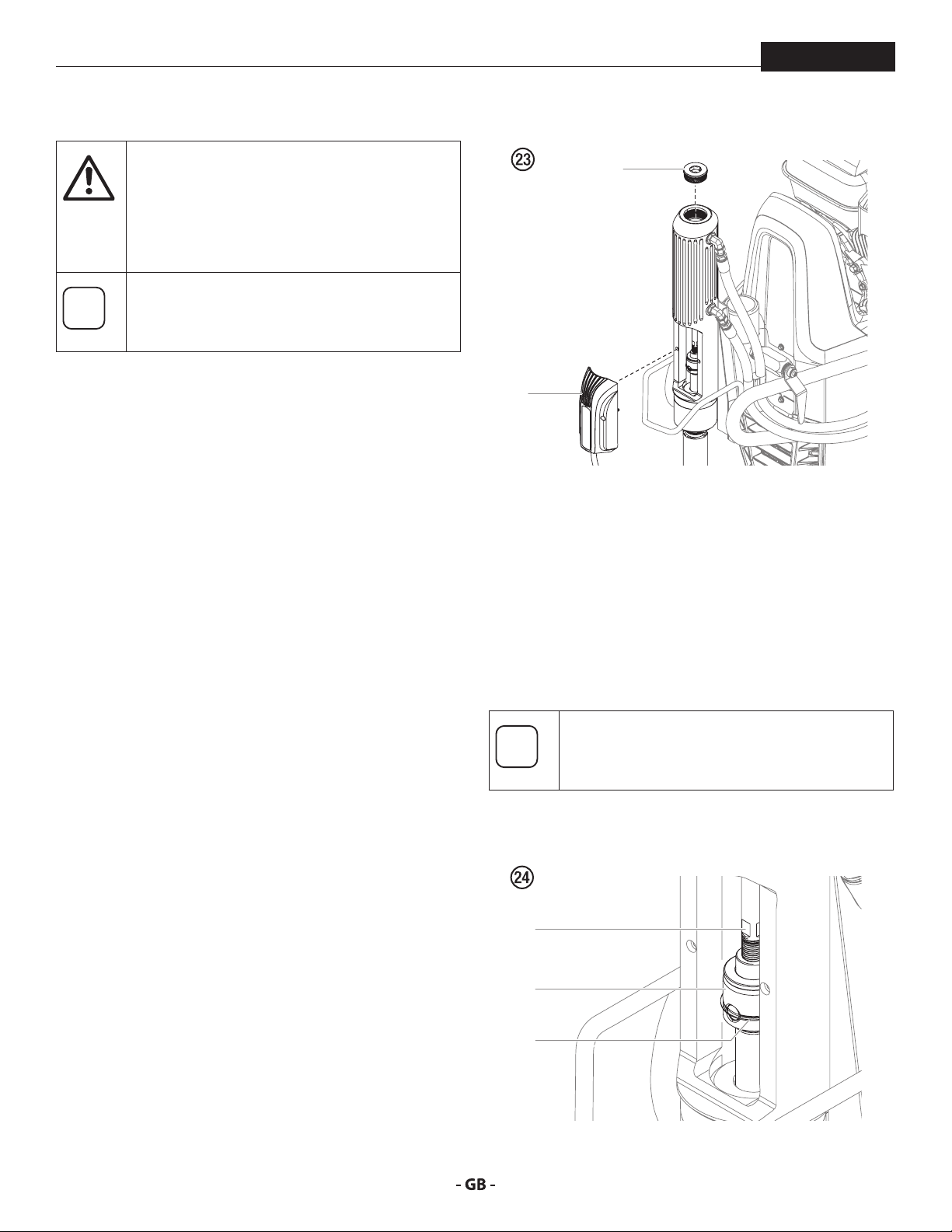
DISASSEMBLING THE HYDRAULIC MOTOR
1. Using a hex wrench, loosen the captive screws that secure
2. Remove the cylinder head plug (2) from the hydraulic
metallic particles left in the motor or entering
it on reassembly may damage the critical parts
and aect its service life and warranty. All parts
should be inspected for absolute cleanliness.
In order to service the hydraulic motor, it is
recommended that the piston be set in the
middle of its stroke. Follow the steps below.
to the lowest setting.
the engine or turn on the electric motor.
back side of the motor/pump and using the smallest tip
available (for slowest piston speed possible), spray water
back in to the bucket (or other waste container). Stop
spraying when the piston is in the desired location.
the PCB board assembly (Fig. 23, item 1) to the hydraulic
motor cylinder. Once removed, the board can hang by its
cord.
motor cylinder.
1
2
3. Using a syringe or sponge, soak up any excess hydraulic
uid in the cavity left by removing the cylinder head plug.
4. In the access area left by the removal of the PCB board
assembly, locate the ats on the bottom of the hydraulic
piston (Fig. 24, item 3). Place a wrench on the hydraulic
piston ats.
5. Slide the retaining ring (4) on the piston coupler (5) up to
clear it of the coupler holes.
6. Carefully insert a screwdriver into one of the open holes of
the piston coupler (5) to secure it.
You may need to twist the entire hydraulic piston
(4) and coupler (5) assembly slightly with the
wrench to gain access to one of the open holes.
7. Loosen the hydraulic piston (4) from the coupler (5) using
the wrench on the ats of the hydraulic piston (4).
4
5
3
26
maintenance
i
At
i
i
PowrBeast
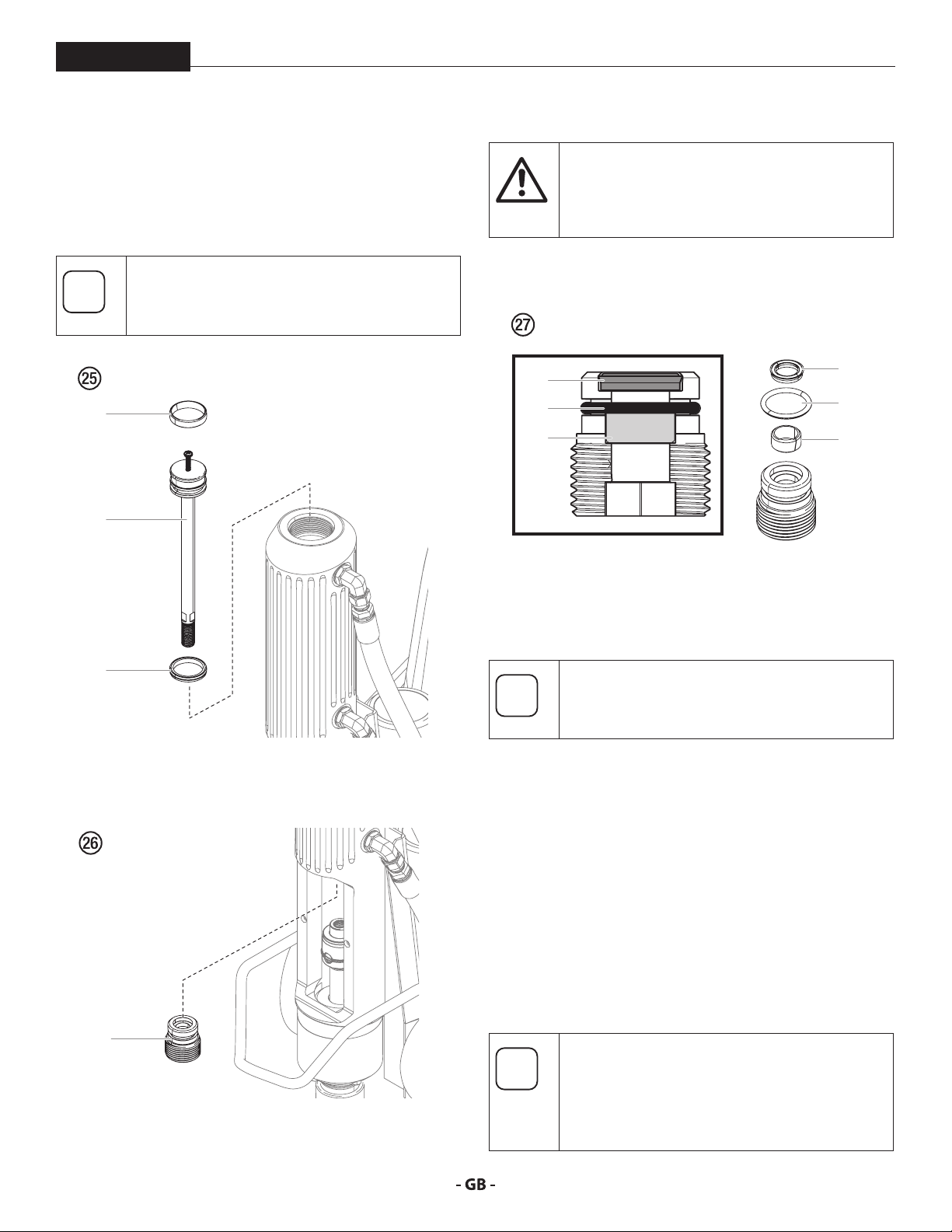
8. Lightly thread a 1/4 - 20 screw into the top of the hydraulic
piston (Fig. 25, item 4). Using the screw, pull the piston
from the top of the hydraulic motor cylinder.
9. Carefully remove the seal (6) and wear ring (7) from the
piston. Replace with new parts from the kit.
Be sure to coat the the new seal and wear ring
with hydraulic oil prior to reinstallation.
6
4
Remove these parts very carefully. Do not scratch
any metal surface of the plug assembly
tention
12. Soak the new parts from the kit in hydraulic oil and reinstall
back onto the plug.
11
10
9
REASSEMBLING THE HYDRAULIC MOTOR
1. Replace the plug assembly (8) into the interior of the
hydraulic motor cylinder. Tighten with the L-shaped hex
wrench.
11
10
9
7
10. Using an L-shaped hex wrench, unthread the plug
assembly (Fig. 26, item 8) from the inside of the hydraulic
motor cylinder.
8
11. Carefully remove the wear ring (Fig. 27, item 9), O-ring (10),
and cup seal with O-ring (11) from the plug.
Inspect the bottom of the hydraulic piston for
any sharp areas that could damage the piston
seal (11) during reinstallation.
2. Replace the hydraulic piston (4) back into the top of the
hydraulic motor cylinder. Using a rubber mallet, carefully
tap the piston down into the cylinder until the ats are
visible in the access area above the piston coupler (5).
3. Remove the 1/4 - 20 screw from the top of the piston
assembly.
4. Using a screwdriver in the open hole of the piston coupler
(5) and a wrench on the ats of the hydraulic piston (4),
reattach the two parts and tighten.
5. Slide the retaining ring on the coupler back in place.
6. Replace the cylinder head plug (2).
7. Replace the PCB board assembly (1).
Once this repair is complete, start the engine or
turn on the electric motor. Allow the unit to run
for a few minutes and then shut it down.
Immediately check the hydraulic oil level and
rell if needed.
27
maintenance
At
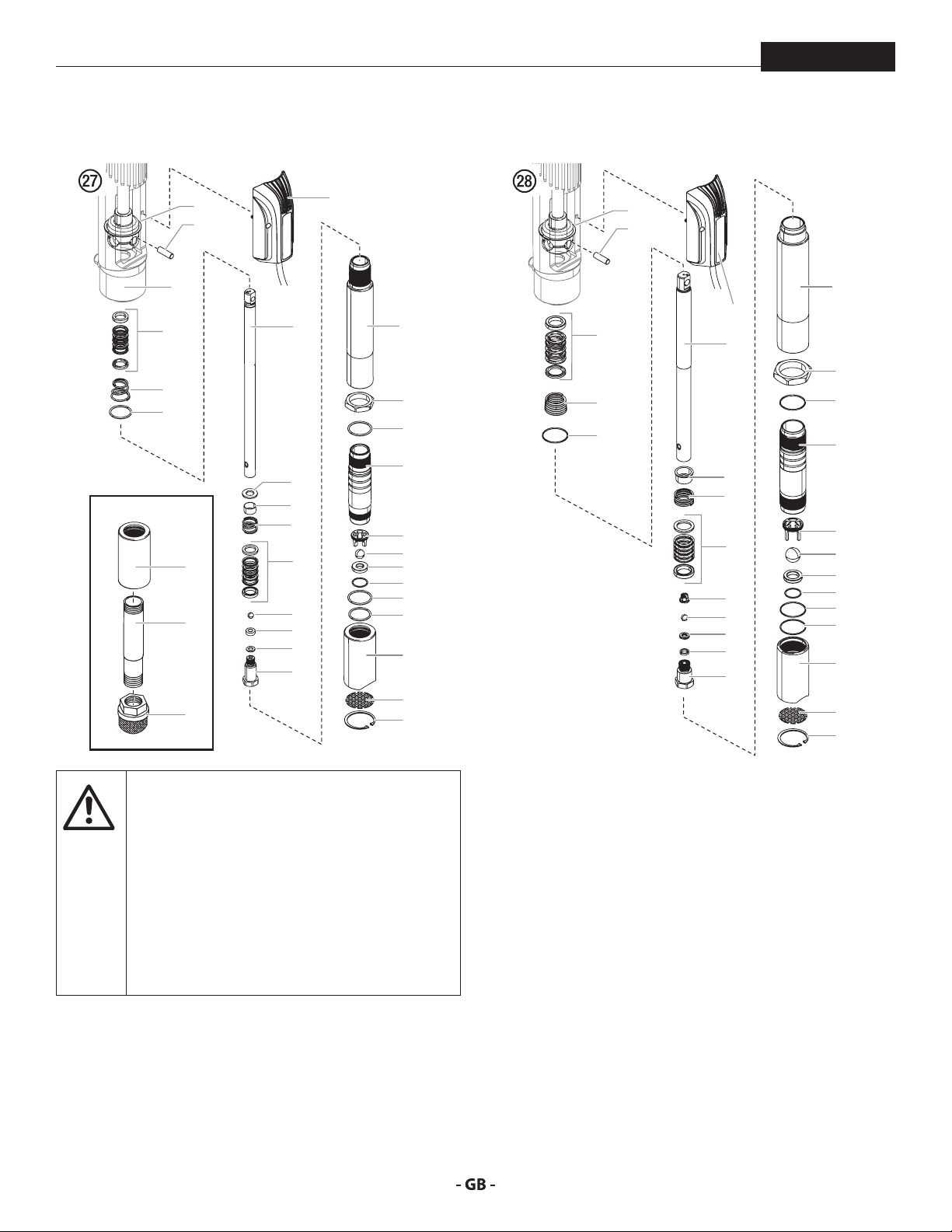
7.9 SERVICING THE FLUID SECTION
PowrBeast
POWRBEAST 4700 / POWRBEAST 4700T
1
2
29
4a
5
3
4700
23
26
27
6
8
7
9
4b
10
11
12
13
30
14
15
31
16
17
18
19
20
21
22
23
24
25
POWRBEAST 7700 / POWRBEAST 9700
1
2
30
4a
5
3
6
8
9
4b
28
10
11
12
13
14
15
31
16
17
18
19
20
21
22
23
24
25
Use of non-Titan service parts may void warranty.
3. PowrBeast 4700 - Remove the siphon tube (26).
4. Spin the uid section removal nut (15) counterclockwise
so that it bottoms out on the threads on the cylinder (16).
5. Place a wrench on the ats of the uid section removal
nut (15). Turn the wrench counterclockwise to loosen the
entire uid section.
6. Carefully pull down the uid section to remove from the
hydraulic motor.
7. In order to service the uid section, stabilize it by securing
the ats of the uid section removal nut (15) in a vise.
tention
Ask for original parts made by Titan for best
services. This pump should receive a routine
servicing after approximately 1,000 hours of use.
Earlier servicing is required if there is excessive
leakage from the top packing or if pump strokes
become faster on one stroke or the other.
The use of Titan Piston Lube (P/N 314-480) is
recommended as an upper packing lubricant.
Do not substitute oil, water, or solvent for an
upper packing lubricant.
8. Unthread the foot valve housing (23) with a strap wrench.
9. Remove upper packing spring (5), and upper packing set
DISASSEMBLING THE FLUID SECTION
1. Using a hex wrench, loosen the captive screws that secure
the PCB board assembly (Fig. 27, item 30) to the hydraulic
motor cylinder. Once removed, the board can hang by its
cord.
2. Slide the retainer ring (1) up with a small screwdriver, then
(4a) from the motor/pump block.
10. Place a wrench on the ats on top of the displacement rod
(6). Using a second wrench, loosen and remove the outlet
valve housing (13) from the displacement rod (6).
11. Remove the seal washer (12), outlet valve seat (11), outlet
valve ball (10), outlet valve cage (28, PowrBeast 7700
push the connecting pin (2) out.
28

maintenance
i
i
i
i
PowrBeast
/ PowrBeast 9700 only), lower packing set (4b), lower
packing spring (9) and spring retainer (8).
12. Using a 1/2” extension bar attached to a 1/2” drive ratchet,
insert the end of the extension bar into the square opening
of the foot valve cage (17) inside the foot valve housing
(23). Unscrew and remove the foot valve cage from the
foot valve housing.
13. Remove the PTFE o-ring (22), foot valve ball (18), foot valve
seat (19), and seat o-ring (20) from the foot valve housing
(23).
14. Remove the o-ring (21) from the pump cylinder (16)
REASSEMBLING THE FLUID SECTION
Use PTFE tape on all threaded pipe connections.
1. Place a new seat o-ring (20) into the groove in the bottom
of the foot valve housing (23).
2. Inspect the foot valve seat (19) for wear. If one side is worn,
ip the seat to the unused side. If both sides are worn,
install a new seat. Place the new or ipped seat (worn
side down) into the bore at the bottom of the foot valve
housing (23).
3. Place a new foot valve ball (18) onto the foot valve seat
(19). Using a 1/2” extension bar attached to a 1/2” drive
ratchet, insert the end of the extension bar into the square
opening of the foot valve cage (17) and screw the foot
valve cage into the foot valve housing (23). Torque the
cage to 240 in./lbs. (20 ft./lbs.).
4. Insert a new PTFE o-ring (22) into the groove of the foot
valve housing (23). Lubricate the o-ring using oil or grease.
5. After soaking the leather packings in oil (preferably linseed
oil), reassemble the lower packing set (4b). Place the set
onto the outlet valve housing (13) with the peak of the
“V” packings pointing down toward the hex on the outlet
valve housing.
All leather packings must be soaked in
CoolFlo hydraulic oil for 15–20 minutes before
installation. Soaking the packings too long will
cause the packings to swell and create diculty
during reassembly.
6. Inspect the outlet valve seat (11) for wear. If one side is
worn, ip the seat to the unused side. If both sides are
worn, use a new seat. Insert the outlet valve cage (28,
PowrBeast 7700 / 9700 only) outlet valve ball (10), new
or ipped seat (worn side away from ball), and a new seal
washer (12) into the displacement rod (6).
7. Clean the threads on the outlet valve housing (13) and
coat the threads with blue Loctite #242. Make sure the
Loctite is only on the threads.
8. Place the lower packing spring (9) onto the outlet valve
housing (13) followed by the spring retainer (8).
9. Screw the displacement rod (6) and the outlet valve
housing (13) together. Tighten in a vise to 50 ft./lbs. (68
Nm).
10. Insert the PTFE o-ring (3) into the upper grove of the
motor/pump block.
11. Insert the upper packing set (4a) into the motor/pump
block with the peak of the “V” packings pointing up toward
the motor.
The packings must be soaked in CoolFlo hydraulic
oil before installation.
12. Place the upper packing spring (5) into the motor/pump
block with the small tapered end facing up toward the
motor/pump block.
13. Insert the displacement rod (6) up through the upper
packings in the motor/pump block.
14. Align the holes in the displacement rod (6) and the
hydraulic piston rod and insert the connecting pin (2).
Replace the retaining ring (1) over the connecting pin.
15. PowrBeast 4700 - Thread the long threads of the pump
cylinder (16) into the motor/pump block and tighten with
a strap wrench.
16. Thread the male threads of the cylinder spacer (14) into
the motor/pump block and tighten with a strap wrench.
Thread the long threads of the pump cylinder (16) into the
cylinder spacer (14) and tighten with a strap wrench.
17. Place the o-ring (21) onto the top grove of the pump
cylinder (16).
18. Thread the foot valve housing (23) onto the pump cylinder
(16), tighten with a strap wrench.
19. PowrBeast 4700 - Install the siphon tube (26).
It is not necessary to over-tighten the foot valve
housing. O-ring seals perform sealing function
without excessive tightening. Full thread
engagement is sucient.
PowrBeast 4700 - For siphon tube attachment,
it is critically important that the threads of the
siphon tube t snugly into the foot valve housing
with the tube PTFE taped and sealed to prevent
air leakage.
29
maintenance
i
At
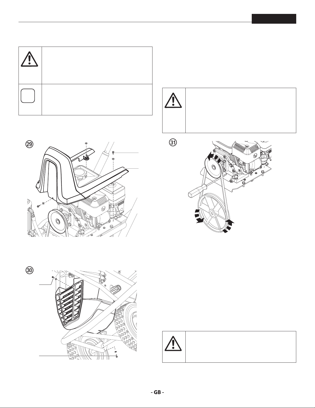
7.10 REPLACING THE BELT
PowrBeast
Before replacing the belt on your unit, make
sure you have performed the “Pressure Relief
Procedure” as illustrated in the Operation section
of this manual. DO NOT attempt this repair while
the unit is running.
The graphics below show a unit with a gas
engine. All instructions given in this section will
apply to both gas engine models and electric
motor models except where noted.
1. Remove the three screws and washers (1) that secure the
top shroud (2) to the cart frame. Remove the shroud.
1
2
4. With the screwdriver in place, use your other hand to
manually turn the belt and pulleys counterclockwise.
Allow the screwdriver to follow the motion of the pulley
and pry the belt outward at the same time. Continue to
turn the pulley approximately 1/2 turn and the belt will
slide o the upper pulley with the help of the screwdriver.
PINCH HAZARD. Make sure your ngers remain
clear of the contact area between the screwdriver
and the pulley. Do not allow your ngers to get
between the belt and pulley as it turns.
BURN HAZARD. Make sure the gas engine has
had time to suciently cool before touching it.
2. Remove the front screw (3) and the bottom screw (4) that
secures the lower shroud to the main unit. Remove the
entire shroud.
3
4
3. Carefully insert the driver end of a screwdriver in between
the belt and upper pulley as shown (g. 31).
REINSTALLATION
1. Loop the the new belt over the top pulley until the belt
engages the pulley groove.
2. Allow the belt to hang from the top pulley. With your
hand, hold the belt in place in approximately the 3:00
position on the lower pulley groove.
3. Use your other hand to manually turn the upper pulley
clockwise. Allow the hand holding the belt on the lower
pulley to follow the motion. The motion of the pulley and
the placement of your hand over the belt on the lower
pulley will allow the the belt to slide into place on the
lower pulley.
Make sure the belt is not pinched or twisted in
any way.
tention
4. Reverse steps 1-2 to reassemble the unit.
30
 Loading...