


Piper J-3 Cub
Assembly Manual
Specifications:
Wingspan: 82.7” (2100mm)
Length: 48” (1215mm) Wing area: 850 in2 (55dm2)
Weight: 6.5-7.5lbs (3-3.5kg) Engine: .46-.61 2 Cycle
.50-.91 4 Cycle Radio: 4 Channel (5 Servos)
Thunder Tiger Piper J-3 Cub ARF Airplane (TTR4532)
Distributed in North America by Ace Hobby Distributors, Inc. • 116 W 19th ST, Higginsville, MO 64037 Phone: 660-584-7121 • www.acehobby.com • E-mail: acehobby@ctcis.net
Warranty
This kit is guaranteed to be free from defects in material and workmanship at the date of purchase. It does not cover any damage caused by use or modification. The warranty does not extend beyond the product itself and is limited only to the original cost of the kit. By the act of building this user-assembled kit, the user accepts all resulting liability for damage caused by the final product. If the buyer is not prepared to accept this liability, it can be returned new and unused to the place of purchase for a refund.
Notice: Adult Supervision Required
This is not a toy. Assembly and flying of this product requires adult supervision.
Read through this book completely and become familiar with the assembly and flight of this airplane. Inspect all parts for completeness and damage. If you encounter any problems, call 660-584-6724 for help.
99206/JE6120
1

INTRODUCTION
One of the most recognized names in aviation history is the Piper J-3 Cub. A child of the Depression, Mr. Piper’s Cub began production in the early ‘30s, evolving into the 65 HP J-3 version in 1939. Proliferating in the years before and during WWII, the Cub has introduced more young men to the joys of flight than any other airplane ever.
Now you can own a part of aviation’s history and enjoy the relaxing and realistic flight characteristics of the venerable J-3 Cub. Thunder Tiger’s ARF J-3 has been meticulously built from the finest material and covered with UltraCote® in the classic Cub Yellow color scheme. Scale details such as wing struts, landing gear bungees, Cub wheels, accurately contoured fuselage, and dummy engine cylinder heads create a headturning beauty. Only a few hours of enjoyable assembly and you are ready to step back in time and be a part of history by flying the classic, IMAA legal J-3 Cub.
PRE-ASSEMBLY NOTES
Before beginning the assembly read the instructions thoroughly to give an understanding of the sequence of steps and a general awareness of the recommended assembly procedures.
By following these instructions carefully and referring to the corresponding pictures, the assembly of your model will be both enjoyable and rewarding. The result will be a well built, easy to assemble A.R.F. model, which you will be proud to display and also provide you flying excitement not unlike its full-scale counterpart.
If you are not an experienced R/C pilot, plan to have a fully competent pilot check your completed model and help you with your first flights. Even though we have tried to provide you with a very thorough instruction manual, R/C models are rather complicated and an experienced modeler can quickly check over your model to help make sure your first flights are successful. Your J-3 Cub is designed for intermediate to advanced pilots.
Before you begin, check the entire contents of your kit against the parts list and photos to make sure that no parts are missing or damaged. This will also help you to become familiar with each component of your plane. If you find that any of the parts are either missing or damaged, please contact Ace Hobby Distributors, Inc., Customer Service (660-584-6704) immediately for replacements.
Note: Neither your dealer nor
Ace Hobby Distributors, Inc., can accept kits for return if construction has begun.
Trial fit each part before gluing it in place. Make sure you are using the correct part and that it fits well before assembling. No amount of glue can make up for a poorfitting part.
TABLE OF CONTENTS
Introduction |
2 |
Other Items Required |
2 |
Items Needed Check List |
3 |
Parts Sketches |
4-5 |
Wing Assembly |
6-9 |
Fuselage Assembly |
10-12 |
Stabilizer Assembly |
12-14 |
Engine & Fuel Tank Installation |
14-15 |
Radio Installation |
16-18 |
Cowl Installation |
19 |
Windshield Installation |
20 |
Wing Strut Attachment |
20-21 |
Balance |
21 |
Control Throws |
21 |
Flying Hints |
22 |
Pre-Flight Checks |
22 |
Safety Precautions |
22 |
Post-Flight Check List |
22 |
|
|
2
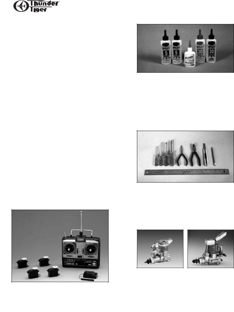
RECOMMENDED TOOLS & MATERIALS
Adhesives:
Instant setting Cyanoacrylate adhesive (thin CA) Slow setting Cyanoacrylate adhesive (thick CA) 10 Minute Epoxy (fast)
20-30 Minute Epoxy (slow) R/C 56 Glue
Tools:
Model knife,T-Pins, 1/2” vinyl tape
Small screwdrivers, Medium screwdrivers Scissors
Steel straight edge
Long nose pliers and diagonal cutting pliers Drill and drill bits
Sanding block
Fine felt tip pen and soft lead pencil Straight building board
R/C System:
4 Channel radio with 5 servos
Engine:
2 cycle: .40 to .61 CID
4 cycle: .50 to .91 CID
Propeller (appropriate for engine type and preferred performance)
Adhesives - You will need two types of adhesives for the Fun Tiger - Epoxy and Instant (cyanoacrylate) adhesives. We recommend that you purchase both 5-minute and 30-minute epoxy to cut down on assembly time, but you can get by with only 30minute epoxy if time is not important.You will also need a small bottle of both “Thick” and “Thin” instant adhesive.
Tools - Model assembly can be much easier if the proper tools are used. Therefore, we have included in our checklist to the left, a complete listing of all the tools we used to assemble our prototype models. As you will notice, many household tools can be utilized during construction.
Engine - The Thunder Tiger PRO-46 and F-54S are the ideal engines for this airplane. These quiet-run-
Radio - A 4-channel radio with five standard servos
ning engines are easy to start, require no special
is required.
break-in periods, are very easy to maintain and will last for years.
3
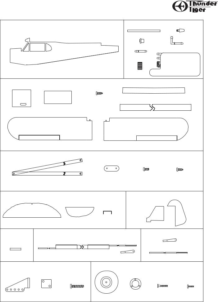
PARTS DRAWINGS
Fuselage AS6029 |
|
|
|
Fuel Tank Set #3263 |
||||
|
|
|
|
|
Silicone Tube (1) |
|
|
Clunk (1) |
|
|
|
|
|
Fuel Stopper (1) |
|
90" Nipple (1) |
|
|
|
|
|
|
Nipple (1) |
|
|
|
|
|
|
|
|
|
|
300 c.c. Tank (1) |
|
|
|
Fuselage(1) |
|
Cap (1) |
|
|
|
|
|
|
|
|
|
|
|
|
|
Wing AS6030 |
|
|
|
|
|
|
|
|
|
|
M2mm x 8mm |
|
Wing Joiner (3) |
|
|||
|
|
|
|
|
|
|
||
Hatch (2) |
Wing Bolt Plate (1) |
Screw (8) |
|
|
|
|
|
|
|
|
|
|
|
|
|||
|
|
|
|
|
Trim Tape (1) |
|
||
|
Left Wing (1) |
|
|
Right Wing (1) |
|
|
||
Wing Struct AS6031 |
|
|
|
|
|
|
|
|
|
|
|
|
|
M3mm x 5mm |
M3mm x 8mm |
||
Wing Struct (2) |
|
Mounting Plate (6) |
Screw (6) |
|
Tapping Screw (6) |
|||
Horizontal Tail AS6032 |
|
|
|
Vertical Tail AS6033 |
||||
|
|
|
|
|
Vertical Fin (1) |
|
|
Rudder (1) |
|
|
|
1/8" Wire |
|
|
|
|
|
Stabilizer (1) |
Elevator (2) |
Elevator Joiner |
(1) |
|
|
|
|
|
Shrink tube |
Aft Pushrods AS6035 |
|
|
Aileron Pushrods #3152 |
||||
AS6034 |
|
|
|
|
|
|
|
|
|
|
|
|
|
|
|
Clevis (2) |
|
Shrink tube (4) |
Stab/Rudder Pushrods(2) |
|
Clevis (2) |
|
Threaded Rod (2) |
|||
Control Horn Set #3151 |
|
Main wheel #3101 |
|
|
|
|||
|
|
M2mm x 15mm |
|
|
M2mm X 6mm |
M2mm X 3mm |
||
Control Horn (2) |
Back Plate (2) |
Screw (4) |
Main Wheels (2) |
Hub Cover(2) |
Screw (6) |
Screw (6) |
||
|
|
|
4 |
|
|
|
|
|

PARTS DRAWINGS
5 |

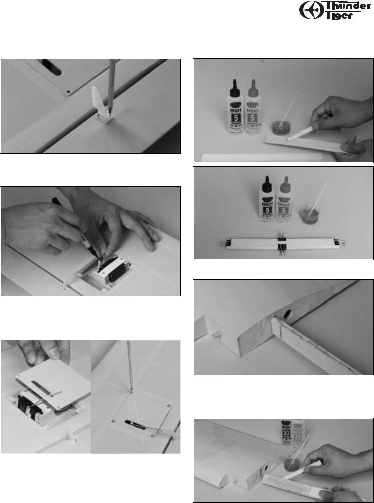
WING ASSEMBLY
Identify the right and left wing panels. Carefully remove the tape that temporarily secures the ailerons to each wing panel.
Carefully remove all hinges from the ailerons and apply a small drop of oil to each hinge on the hinge pin. (Photo 1)
With the right wing panel once again upside down on the building board, determine the aileron servo location (2nd wing bay in from the inboard edge of the aileron). Using a felt tip pen, draw a cutting line 3/16” inside the bay. Carefully cut away the covering and seal the edges using a heating iron. (Photos 5, 6 & 7)
Photo 1
Apply 20-30 Minute Epoxy to one half of each hinge and insert into the right aileron. Set aside to cure and repeat procedure for the left aileron. (Photo 2)
Photo 2
Apply 20-30 Minute Epoxy to the exposed portion of the hinges on the right aileron. Carefully fit the aileron into the right wing panel. Wipe off any excess epoxy using denatured (rubbing) alcohol. Set aside to cure. Repeat the same procedure for the left wing aileron and wing panel. (Photo 3)
Photo 3
Photo 5
Photo 6
Photo 7
Obtain two servo extensions that give you the necessary lead length for your aileron servos (12” or so). Join the aileron servo and servo extension. Cover the connection with heat shrink tubing provided and using a heat gun shrink the tubing over the connectors. (Photo 8).
Place the right wing panel upside down on the building board.
Locate the exit hole for the aileron extension. Using a model knife, Photo 8 carefully cut and remove the covering material covering the exit hole.
Repeat the procedure for the left wing panel. (Photo 4)
Photo 4
6

Insert a piece of piano wire through the root rib of the wing panel and “fish” the aileron servo lead through the wing. (Photos 9 & 10)
Photo 9
Photo 10
Use a pair of tweezers to pull the servo lead through the exit hole in the wing panel (Photo 11).
Photo 11
Place the servo in the wing panel in the servo mount. (Photo 12)
Photo 12
WING ASSEMBLY
Place the servo hold down plate over the servo and drill through the plate into the servo mount taking caution not to drill through the wing. (Photo 13)
Photo 13
Using M2.5X8 wood screws, screw the servo hold down plate in place (Photo 14)
Photo 14
Locate the correct servo cover and install in the right wing panel.
Drill 4 3/64” holes at the four corners. (Photo 15)
Photo 15
7
WING ASSEMBLY
Place the control horn on the aileron and align with the servo horn slot in the hatch cover. Drill holes using the control horn as a template. Secure the control horn with two M2x12 screws and the backer plate. (Photo 16)
Photo 16
Locate the control clevis and thread onto the push rod. Snap the clevis onto the control with the servo at the neutral position. Mark the clevis for the “Z” bend. (Photo 17)
Photo 17
Remove the clevis, cut off the excess wire and insert the “Z” bend through the hatch cover then into the servo horn. Snap the clevis onto the control horn. Secure the hatch cover with 4 M2x8 wood screws. (Photos 18 & 19)
Photo 18 |
Photo 19 |
|
|
Repeat the above procedures for the left wing panel.
SUGGESTION: Secure any clevis/control horn connection with a piece of medium fuel tubing about 1/4” long. (Not Shown)
Locate the three wing joiners (2 plywood and 1 aluminum). Apply a coat of 5-10 Minute Epoxy to each side of the aluminum joiner and mate the 2 plywood joiner to it. Clamp the assembly together and set aside to cure. (Photos 20 & 21)
Photo 20
Photo 21
Draw a center line on the wing joiner and trial fit into the spar box on each wing panel. Sand to fit as necessary. (Photo 22)
Photo 22
When the two wing panels match up perfectly, apply 30-45 Minute Epoxy to the wing joiner on one half only. Liberally apply 30-45 Minute Epoxy to the spar box in the right wing panel. Insert the joiner into the spar box wiping off any excess epoxy. Set aside to cure. (Photo 23)
Photo 23
8
 Loading...