


EK4-S2

1/8 OFF-ROAD, 4WD MONSTER TRUCK
No.6216
JD1440.V3
Thunder Tiger Corporation guarantees this model kit to be free from defects in both material and workmanship.
The total monetary value under warranty will in no case exceed the cost of the original kit purchased. This warranty
does not cover any components damaged by use or modification. Part or parts missing from this kit must be
reported within 60 days of purchase. No part or parts will be sent under warranty without proof of purchase.
To receive part or parts under warranty, the service center must receive a proof of purchase and/or the defective
part or parts. Should you find a defective or missing part, contact the authorized Thunder Tiger Service/Distributor
nearest you. Under no circumstances can a dealer or distributor accept return of a kit if assembly has started.
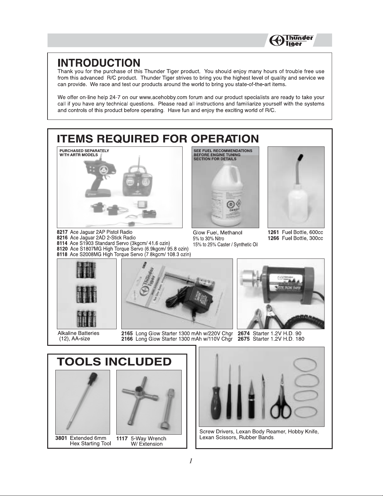
INSTALLING THE RADIO GEAR
1
a
d
g
a. Take out the 4 screws on the chassis securing the plastic servo tray.
b. Install the servos with tap screws. Notice the orientation of the steering and throttle servo output shafts.
c. Install the receiver switch onto the rear of the receiver box with its original screws.
d. Properly plug the connectors/wires into the receiver: steering servo connector/wire into channel 1 slot, throttle servo
connector/wire into channel 2 slot, and battery switch connector/wire into battery slot.
e. Remove the receiver box top's 4 screws and place the receiver and the wires inside the receiver box, thread the receiver
antenna/wire through the box top hole, and reinstall the box top.
f. Thread the receiver antenna/wire through the antenna tube, then install the antenna tube onto the box top hole.
g. Install 4 AA size alkaline batteries in receiver battery box and strap the battery box onto the battery plate with two large
nylon zip-ties.
h. Connect the receiver battery box wire/connector to the receiver switch wire/connector.
i. Install the battery box & plate onto the posts, then use the large body clips to secure the plate onto posts.
b
e
h
c
f
i
2
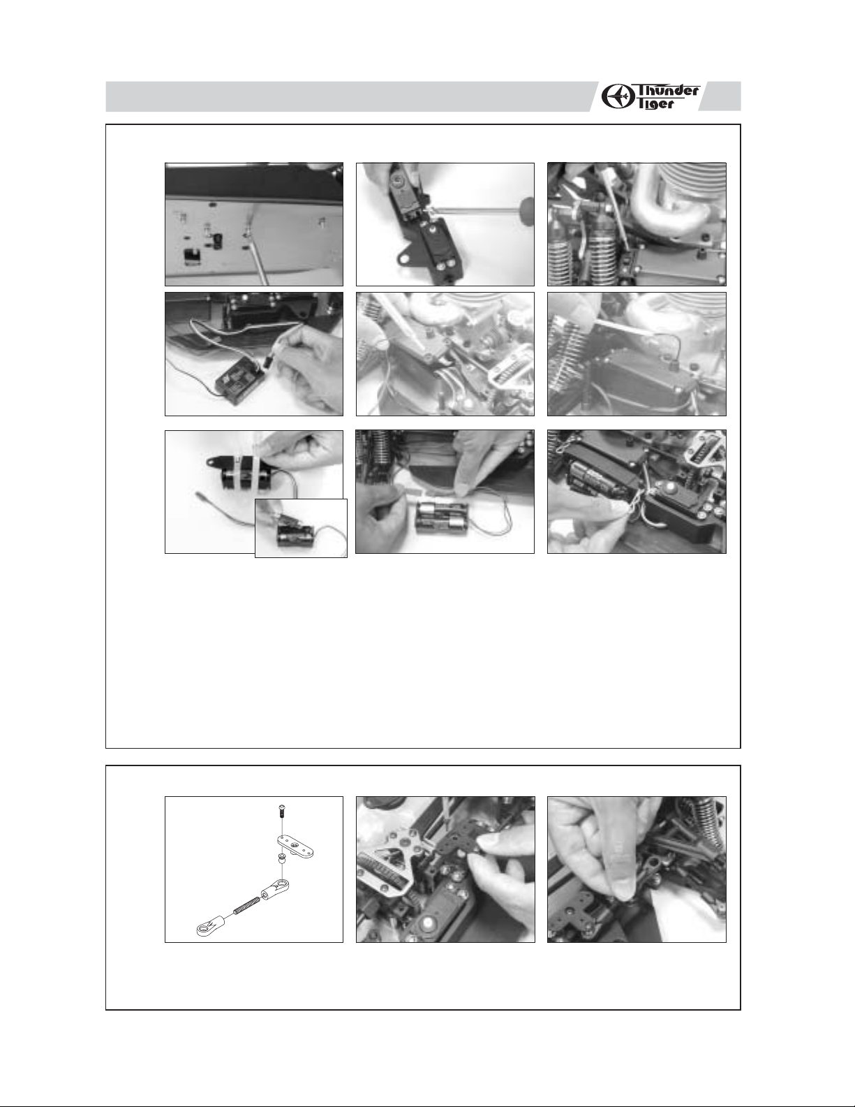
INSTALLING STEERING SERVO LINKAGE
a
a.
Build the steering linkage as shown on the diagram
b.
Install the servo horn onto steering servo output shaft with its original screw.
c.
Pop the tie-end onto the standoff ball on the steering rack.
b
.
2
c

INSTALLING THROTTLE LINKAGE
3
4
a
To brake cam
a.Build the throttle/brake linkages as shown on the diagram.
b.The throttle/brake linkage should appear as shown.
c.Install the servo horn onto throttle sero output shaft.
To engine
carburetor
lever
b
c
CHARGING THE GLOW PLUG IGNITER
Thunder Tiger Optional Part #2165, 1300MAH Glow Starter w/220V Charger.
Thunder Tiger Optional Part #2166, 1300MAH Glow Starter w/110V Charger.
a
b c
d
a. Plug the charger into an AC outlet.
b. Line up the charging adapter with the tip of the glow plug igniter.
c. Pull on the glow plug igniter lever to accept the charging adapter.
d. Plug the charging adapter into the glow plug igniter. At this point, the small red LED indicator on the
charger should light up indicating the charging sequence is in progress.
e. Unplug the glow plug igniter from charger after charging is complete. Pull on the glow plug igniter
lever.
f. Pull the charging adapter out of the glow plug igniter.
Charge the new glow plug igniter for 16 to 24 hours on the first charge. For subsequent charges, charge
it about 12 hours before next use.
NOTE:
If the igniter gets warm or hot during the charge, unplug the igniter from charger immediately. A warm /
hot igniter means the igniter is overcharged. Overcharging can damage the internal battery in the igniter;
thus, shortening its life.
fe
3
 Loading...