


No.6218--F
1/8 4WD NITRO MONSTER TRUCK
JD6224
Thunder Tiger Corporation guarantees this model kit to be free from defects in both material and workmanship. The total monetary value under warranty will in no case exceed the cost of the original kit purchased. This warranty does not cover any components damaged by use or modification. Part or parts missing from this kit must be reported within 60 days of purchase. No part or parts will be sent under warranty without proof of purchase. To receive part or parts under warranty, the service center must receive a proof of purchase and/or the defective part or parts. Should you find a defective or missing part, contact the authorized Thunder Tiger Service/Distributor nearest you. Under no circumstances can a dealer or distributor accept return of a kit if assembly has started.
INTRODUCTION
Thank you for purchasing the Thunder Tiger MTA-4 nitro monster truck. Thunder Tiger strives to bring you the highest level of quality and service we can provide. We race and test our products around the world to bring you state-of-the-art items.
This User Guide contains the steps you will use to prepare and use your new vehicle. Please read all instructions and familiarize yourself with the systems and controls of this product before operating. You should enjoy many hours of trouble free use from this advanced R/C product. We offer on-line help 24-7 on our www.acehobby.com forum and our product specialists are ready to take your call if you have any technical questions. Have fun and enjoy the exciting world of R/C.
ITEMS REQUIRED FOR OPERATION
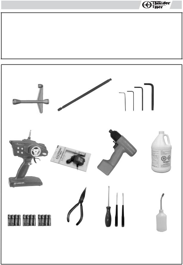
Tools included
MTA-4 Nut Wrench
Items required for operation
Glow Igniter 110/220/240V
3CH pistol radio with hi-torque servos
(Included in the RTR box)
Allen Wrench Set
(5sizes-1.5mm, 2.0 mm, 2.5mm, 3.0mm, 5.0mm)
Fuel (10%-30% only. See Fuel Selection on STEP 15)
AA Batteries (12) |
Needle Nose Pliers |
Phillips Screwdrivers |
|
|
Fuel Bottle |
||
|
|
Slotted Screwdriver |
|
Helpful Items |
|
|
300c.c./600c.c. |
|
|
|
|
Filter Oil |
|
|
|
Thread-Locking Adhesive |
|
|
|
After Run Oil |
|
|
|
1
WARNING
Thank you for purchasing a Thunder Tiger Product. Please read all instructions thoroughly before operation.
1.This product is not a toy. It is a high performance model product. It is important to familiarize yourself with the model, its manual, and its construction before assembly or operation.
2.Do not operate model products in rain, on public roads, near crowds, near airport, or near areas with restricted radio operation.
3.Always keep fuel away from heat, open flame and the reach of children! Only operate in open, well-ventilated area. Store fuel in cool, dry area. Keep the fuel bottle cap tightly closed. Clean up any leak or excess fuel before starting the engine.
4.This product, its parts, and its construction tools can be harmful to your health. Always exercise extreme caution when assembling and/or operating this product. Do not touch any part of model which rotates.
5.Check your radio frequency with the proper operating frequency of the area or country. Always check to see if there are any modelers operating on the same frequency as your are. Also, check your radio for proper operation before operating a mode.
6.Improper operations may cause personal and/or property damage. Thunder Tiger and its distributor have no control over damage resulting from shipping, improper construction, or improper usage.
7.Thunder Tiger assumes and accepts no responsibility for personal and/or property damages resulting from the use of improper building materials, equipment and operations. By the act of assembling or operating this product, the user accepts all resulting liability. If the buyer is not prepared to accept this liability, then he/she should return this kit in new, unassembled, and unused condition to the place of purchase.
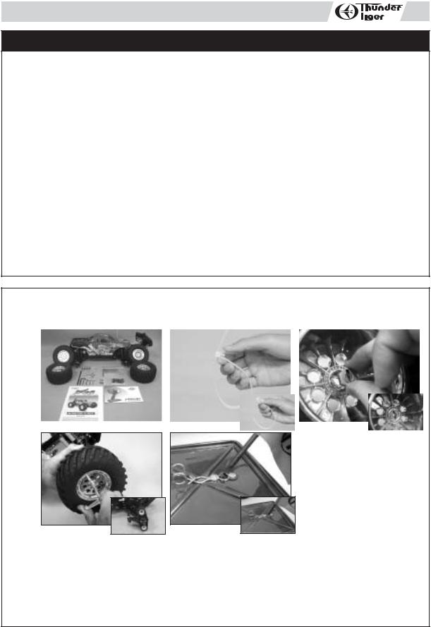
1UNRAPPING THE TRUCK FROM BOX AND INSTALLING THE TIRE & FLAG
a |
|
b |
|
|
c |
|
||
|
|
|
|
|
|
|
|
|
|
|
|
|
|
|
|
|
|
|
|
|
|
|
|
|
|
|
d e
a.Remove the truck, radio, and accessories from box.
b.To unlock zip-tie, press on the small lever. Pull on the zip-tie while keeping the small lever pressed. Pull the zip-tie out completely.
c.Insert the (PD1502) wheel hex driver into both sides of the front/ rear wheel.
d.Install the wheel assembly, lining up the roll pin with the slot in the wheel. Thread on the locknut and washer using nut wrench supplied.
e.Install the flag onto the mount with the attached screw in the bag.
2
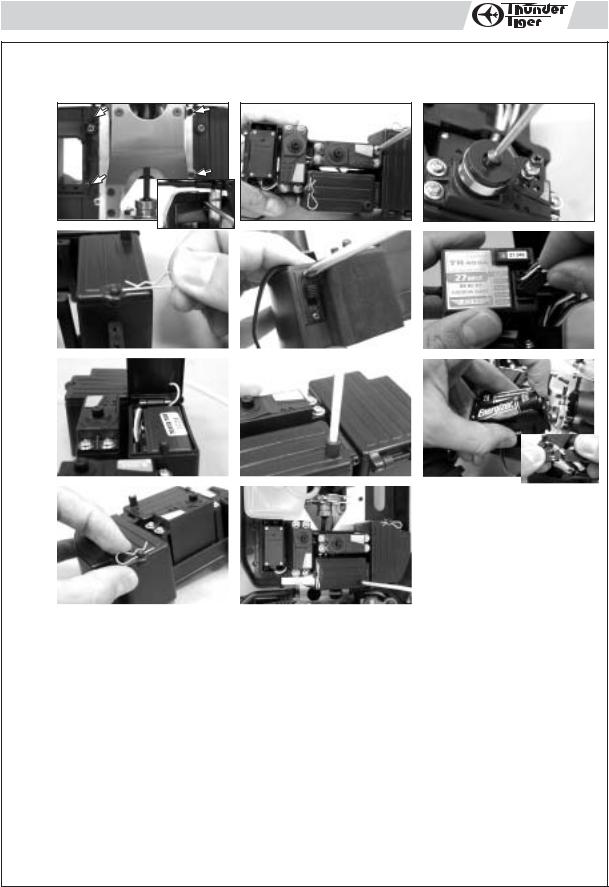
INSTALLING THE RADIO GEAR
2 a |
b |
c |
Skip if already assembled in RTR version
d |
|
e |
|
f |
|
|
|
|
|
g |
|
h |
|
i |
|
|
|
|
|
|
|
|
|
|
|
|
|
|
|
|
|
|
|
|
|
|
|
j |
|
K |
|
|
|
a.Use a Phillips screwdriver to remove two 3x10mm and two 3x14mm Philip screws on the bottom of chassis, and then take out the radio tray from the car.
b.Install the servos with tap screws. Notice the orientation of the steering, throttle and FWD/REV servo output shafts.
c.Install the servo saver onto steering servo output shaft.
d.Take out the large body clip on the receiver box and battery box to open the box top.
e.Install the receiver switch onto the side of the battery box with its original screws.
f.Properly plug the connectors/wires into the receiver, steering servo connector/wire into channel 1 slot, throttle servo connector/wire into channel 2 slot, FWD/REV servo connector/wire into channel 3 slot and battery switch connector/wire into battery slot.
g.Place the receiver and the wires inside the receiver box, thread the receiver antenna/wire through the box top hole, and reinstall the box top with large body clip
h.Thread the receiver antenna/wire through the antenna tube, and then install the antenna tube onto the box top hole.
i.Install 4 AA size alkaline batteries into battery holder and connect the battery holder wire/connector to the receiver switch wire/connector.
j.Install the battery holder into the enclosed battery box with large body clip.
k.Reassemble the radio tray on the chassis with its original screws.
3
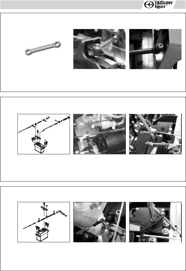
INSTALLING STEERING SERVO LINKAGE
3 |
|
|
|
|
|
a |
|
b |
|
c |
|
|
|
|
|
|
|
Skip if already assembled in RTR version
a.Find the steering linkages in the part bag as shown on the diagram.
b.Install the steering linkage rod onto steering servo saver.
c.Pop the linkage end onto the standoff ball on the steering rack.
INSTALLING THROTTLE/BRAKE LINKAGE
4 a |
b |
c |
Skip if already assembled in RTR version
a.Build the throttle/brake linkages as shown on the diagram.
b.Secure the brake cam lever onto brake cam with setscrew.
c.Install the servo horn onto throttle servo output shaft.
INSTALLING FWD/REV LINKAGE |
|
|
5 a |
b |
c |
a.Build the FWD/REV linkage rod as shown on the diagram.
b.Pop the linkage end onto the standoff ball on the FED/REV shifting gears
c.Install the servo saver onto FWD/REV servo output shaft.
4
 Loading...