


LM158, LM158A, LM258, LM258A
LM358, LM358A, LM358Y, LM2904, LM2904Q
DUAL OPERATIONAL AMPLIFIERS
SLOS068C – JUNE 1976 – REVISED JUL Y 1998
1
POST OFFICE BOX 655303 • DALLAS, TEXAS 75265
D
Wide Range of Supply Voltages:
– Single Supply...3 V to 30 V
(LM2904 and LM2904Q...3 V to 26 V) or
– Dual Supplies
D
Low Supply-Current Drain Independent of
Supply Voltage . . . 0.7 mA Typ
D
Common-Mode Input Voltage Range
Includes Ground, Allowing Direct Sensing
Near Ground
D
Low Input Bias and Offset Parameters:
– Input Offset Voltage ...3 mV Typ
A Versions ...2 mV Typ
– Input Offset Current...2 nA Typ
– Input Bias Current...20 nA Typ
A Versions . . . 15 nA Typ
D
Differential Input Voltage Range Equal to
Maximum-Rated Supply Voltage . . . ±32 V
(LM2904 and LM2904Q...±26 V)
D
Open-Loop Differential Voltage
Amplification . . . 100 V/mV Typ
D
Internal Frequency Compensation
description
These devices consist of two independent, high-gain, frequency-compensated operational amplifiers designed
to operate from a single supply over a wide range of voltages. Operation from split supplies also is possible if
the difference between the two supplies is 3 V to 30 V (3 V to 26 V for the LM2904 and LM2904Q), and V
CC
is at least 1.5 V more positive than the input common-mode voltage. The low supply-current drain is independent
of the magnitude of the supply voltage.
Applications include transducer amplifiers, dc amplification blocks, and all the conventional operational
amplifier circuits that now can be more easily implemented in single-supply-voltage systems. For example,
these devices can be operated directly from the standard 5-V supply used in digital systems and easily provides
the required interface electronics without additional ±5-V supplies.
The LM2904Q is manufactured to demanding automotive requirements.
The LM158 and LM158A are characterized for operation over the full military temperature range of –55°C to
125°C. The LM258 and LM258A are characterized for operation from –25°C to 85°C, the LM358 and LM358A
from 0°C to 70°C, and the LM2904 and LM2904Q from –40°C to 125°C.
logic diagram (each amplifier)
IN+
IN–
OUT
+
–
Please be aware that an important notice concerning availability, standard warranty, and use in critical applications of
Texas Instruments semiconductor products and disclaimers thereto appears at the end of this data sheet.
Copyright 1998, Texas Instruments Incorporated
PRODUCTION DATA information is current as of publication date.
Products conform to specifications per the terms of Texas Instruments
standard warranty. Production processing does not necessarily include
testing of all parameters.
1
2
3
4
8
7
6
5
1OUT
1IN–
1IN+
GND
V
CC
2OUT
2IN–
2IN+
D, JG, P, OR PW PACKAGE
(TOP VIEW)
3212019
910111213
4
5
6
7
8
18
17
16
15
14
NC
2OUT
NC
2IN–
NC
NC
1IN–
NC
1IN+
NC
LM158, LM158A . . . FK PACKAGE
(TOP VIEW)
NC
1OUT
NCNCNC
NC
GND
NC
CC+
V
2IN+
NC – No internal connection
On products compliant to MIL-PRF-38535, all parameters are tested
unless otherwise noted. On all other products, production
processing does not necessarily include testing of all parameters.
LM158, LM158A, LM258, LM258A
LM358, LM358A, LM358Y, LM2904, LM2904Q
DUAL OPERATIONAL AMPLIFIERS
SLOS068C – JUNE 1976 – REVISED JUL Y 1998
2
POST OFFICE BOX 655303 • DALLAS, TEXAS 75265
AVAILABLE OPTIONS
PACKAGED DEVICES
T
A
V
IO(max
)
AT 25°C
SMALL
OUTLINE
(D)
†
CHIP
CARRIER
(FK)
CERAMIC
DIP
(JG)
PLASTIC
DIP
(P)
TSSOP
(PW)
‡
CHIP
FORM
(Y)
°
°
7 mV LM358D — — LM358P LM358PW LM358Y
0°C to 70°C
3 mV — — — LM358AP — —
°
°
5 mV LM258D — — LM258P — —
–
25°C to 85°C
3 mV — — — LM258AP — —
°
°
LM2904D — — LM2904P LM2904PW —
–
40°C to 125°C
7 mV
LM2904QD — — LM2904QP — —
°
°
5 mV LM158D LM158FK LM158JG LM158P — —
–
55°C to 125°C
2 mV — LM158AFK LM158AJG — — —
†
The D package is available taped and reeled. Add the suffix R to the device type (e.g., LM358DR).
‡
The PW package is only available left-end taped and reeled.
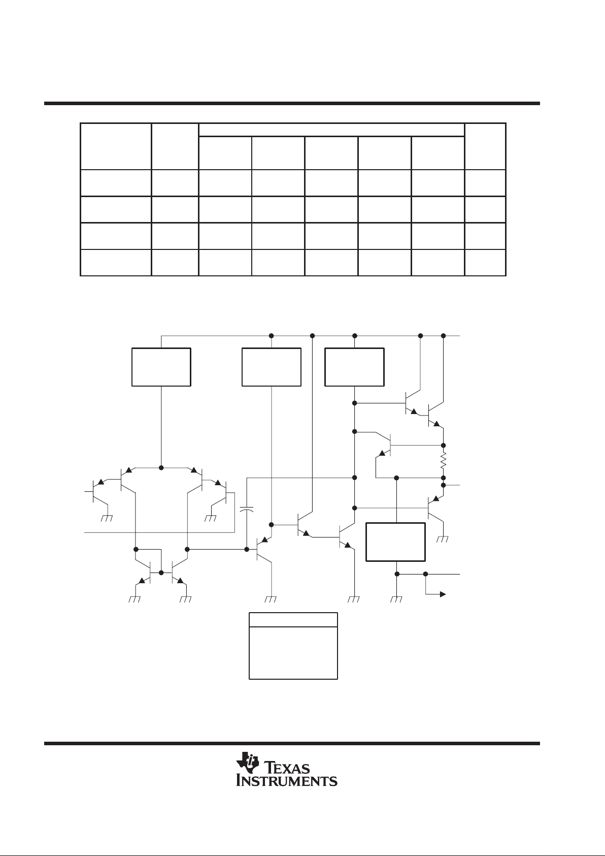
schematic (each amplifier)
V
CC+
OUT
GND (or V
CC–
)
To Other Amplifier
IN–
IN+
≈ 6-µA
Current
Regulator
≈ 6-µA
Current
Regulator
≈ 100-µA
Current
Regulator
≈ 50-µA
Current
Regulator
Epi-FET
Diodes
Resistors
Transistors
Capacitors
COMPONENT COUNT
1
2
7
51
2

LM158, LM158A, LM258, LM258A
LM358, LM358A, LM358Y, LM2904, LM2904Q
DUAL OPERATIONAL AMPLIFIERS
SLOS068C – JUNE 1976 – REVISED JUL Y 1998
3
POST OFFICE BOX 655303 • DALLAS, TEXAS 75265
LM358Y chip information
These chips, when properly assembled, display characteristics similar to the LM358. Thermal compression or
ultrasonic bonding can be used on the doped-aluminum bonding pads. Chips can be mounted with conductive
epoxy or a gold-silicon preform.
Chip Thickness: 15 Typical
Bonding Pads: 4 × 4 Minimum
T
J(max)
= 150°C
Tolerances Are ±10%.
All Dimensions Are in Mils.
No Backside Metallization
Pin (4) is Internally Connected to Backside of Chip.
BONDING PAD ASSIGNMENTS
47
57
(7) (6) (5)
(8)
(4)
(3)
(2)(1)
1IN+
1IN–
1OUT
+
–
(2)
(3)
(1)
V
CC+
(8)
2OUT
2IN+
V
CC–
(4)
+
–
2IN–
(5)
(6)
(7)
 Loading...