

Page 1

Snow Sensor 095
Installation & Operation Manual
095_D
05/13
Snow Melting
Replaces: New
© 2013
095_D - 05/13
1 of 8
A Watts Water Technologies Company
The Snow Sensor 095 is an aerial mounted sensor that detects falling snow and
allows a tekmar Snow Melting Control 653 or 654 to automatically start the snow
melting equipment. System stop is provided by the control’s timer or by manual
disable. The 095 mounts to a nominal 1/2” (16 mm) metal or PVC conduit or pole. The
095 is well suited for adding automatic start to an existing snow melt system.
For use with tekmar Snow Melting Control type: 653 or 654
Introduction
Snow
Sensor
095
Page 2
© 2013 095_D - 05/13
2 of 8
A Watts Water Technologies Company
Installation
Caution
Improper installation and operation of this control could result in damage to
the equipment and possibly even personal injury or death. It is the installer’s
responsibility to ensure that this control is safely installed according to all
applicable codes and standards. Please follow these step-by-step instructions
to gain a full understanding of this device.
Step 1 - Check the Contents
Check the contents of this package. If any of the contents listed are missing or
damaged, please refer to the Limited Warranty and Product Return Procedure on
the back of this brochure and contact your wholesaler or tekmar sales representative
for assistance.
Type 095 includes • One Snow Sensor 095 • One Installation and Operation
Manual 095_D.
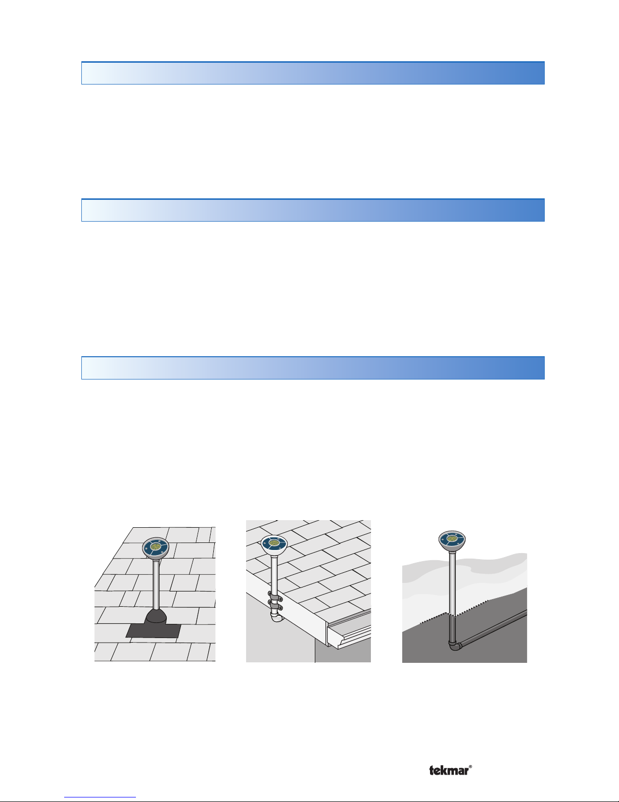
Step 2 - Choosing a Location for the Sensor
The sensor should be installed outside on a nominal 1/2” (16 mm) PVC or rigid
metal conduit pole either on a roof or to the side of the snow melting surface. The
sensor must be located away from trees, building overhangs or other locations
that may interfere with falling snow. Avoid installing in locations where the sensor
may be vandalized. It is best to point the front face of the sensor in the direction
of any prevailing wind.
Roof Mounted
Conduit fastened to
fascia board
Ground Mounted
Conduit run under-
ground with a pole
above surface
Roof Mounted
Ensure water-proof
installation with flashing
boot or similar method
Page 3
© 2013 095_D - 05/13
3 of 8
A Watts Water Technologies Company
Step 3 - Rough In Wiring
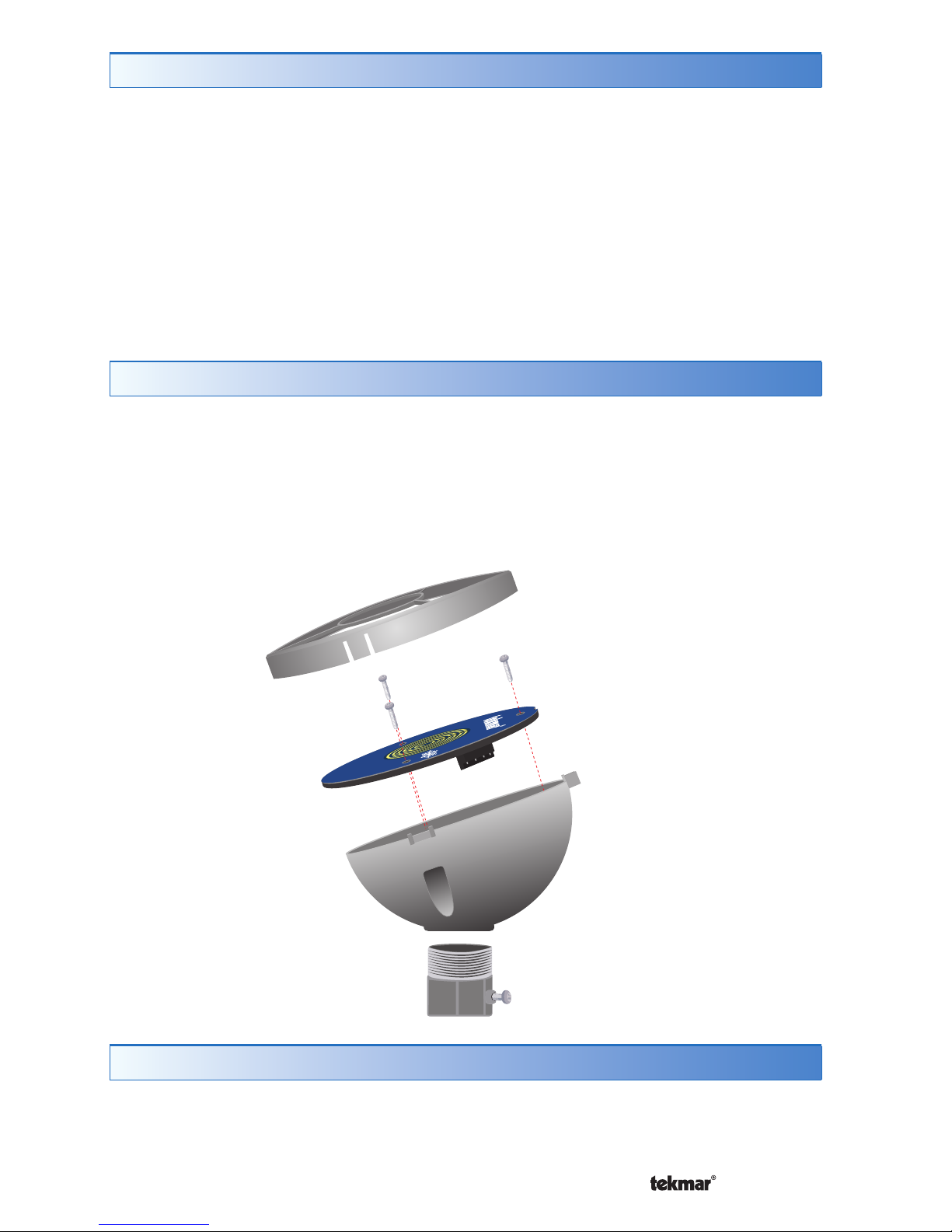
Step 4 - Disassembly
Install a nominal 1/2” (16 mm) PVC or metal conduit from the tekmar Snow Melting
Control to the chosen sensor location. Pull 4 conductor 18 AWG wire from the
sensor location to the control location through the conduit. The maximum wire
length between the sensor and the control is 500’ (150 m).
If using PVC conduit, do not run the wires parallel to telephone or power lines. If the
sensor wires are located in an area with strong sources of electromagnetic noise,
shielded cable or twisted pair should be used. If using shielded cable, one end
of the shield wire should be connected to the Com terminal on the Snow Melting
Control and the other end should remain free. The shield must not be connected
to earth ground.
1. Remove the outer ring by pulling up on the three catches.
2. Remove the three screws.
3. Remove the blue sensor disk from the sensor enclosure.
Avoid scratching any part of the surface of the blue sensor disk.
Scratches will result in corrosion not covered by warranty.
Step 5 - Painting the Sensor
The sensor enclosure is made of an off-white plastic material that is UV stable.
The plastic enclosure may be spray painted to match the color of the building. Do
not paint the blue sensor disk as this will damage the sensor.
Outer Ring
Blue Sensor Disk
Sensor
Enclosure
Conduit Adapter
(not included)
Page 4

© 2013 095_D - 05/13
4 of 8
A Watts Water Technologies Company
Step 7 - Wiring
Remove the wiring terminal block by pulling up from the blue sensor disk. Connect
the 4 conductor wire to the yellow (YEL), blue (BLU), red (RED) and black (BLK)
wiring terminations. If the installed 4 conductor cable uses a different color code,
then make a note of the wire color versus the wiring terminal color names. Push
the wiring terminal plug onto the pins of the blue sensor disk. At the Snow Melting
Control location, connect the corresponding wires to the yellow, blue, red and
black wire terminations.
YEL
BLU
RED
BLK
Snow Sensor 095
Aerial Mounting
Designed & Assembled in Canada
www.tekmarControls.com
Step 6 - Mounting
The conduit pole can be either PVC plastic or rigid metal. The conduit pole should
be mounted plumb using a level.
When using PVC plastic conduit a nominal 1/2” (16mm) PVC male terminal
adapter with locknut is recommended.
When using rigid metal, a nominal 1/2” (16mm) rigid metal conduit adapter with
set screw is recommended.
1. Pull the 4 conductor wire through the conduit.
2. Install the sensor body with conduit adapter to the conduit. For PVC conduit
use PVC cement adhesive. For rigid metal conduit, tighten the set screw until
the conduit adapter is firmly attached to the conduit.
3. Fish the 4 conductor wire though the sensor body and place on top of the
conduit adapter. Point the sensor body towards the prevailing wind direction, if
any. Thread the locknut onto the conduit adapter and screw until tight.
•
•
Page 5

© 2013 095_D - 05/13
5 of 8
A Watts Water Technologies Company
Testing and Troubleshooting
If the Snow Melt Control shows an error message describing a sensor failure,
perform the following test procedure:
The 4 conductor wires at the sensor should be disconnected (unplug wiring
terminal plug).
Use a good quality electrical testing meter with an ohm scale range of 0 to
2,000,000 Ohms.
Using the ohmmeter and standard testing practices, measure the resistance
between:
1. The yellow (YEL) and black (BLK) wiring terminals to measure a 10 kΩ sensor
and use the Temperature vs. Resistance Table to calculate the approximate
temperature reading. Measure the surface temperature of the 095 blue sensor
disk and compare versus the yellow to black temperature reading.
2. Measure the resistance between the blue (BLU) and black (BLK) wiring
terminals. When the sensor surface is clean and dry, the reading should be
2,000,000 Ohms. When the sensor surface is wet it should be between 10,000
and 300,000 Ohms.
3. Measure the resistance between the red (RED) and black (BLK) wiring terminals
This reading should be between 45 to 47 Ohms.
If resistance readings are outside of the normal operating range, the sensor
has failed. The blue sensor disk can be replaced with the part number M3065
“Replacement Kit for Snow Sensor 095”.
•
•
Maintenance
The sensor is installed in a harsh environment. Accumulation of dirt on the surface
of the sensor may affect snow detection. The sensor should be checked on a
periodic basis and, when necessary, cleaned.
1. Remove the outer ring by pulling up on the three catches.
2. A cloth with warm soapy water can be used to clean any dirt.
3. Rinse with water.
4. Align the three notches of the outer ring with the sensor body and push down
until each of the three corners have snapped on tight.
Step 8 - Assembly
1. Align the blue sensor disk tekmar logo with the highest point of the sensor
enclosure body. The blue sensor disk has a notch that ensures the sensor is
installed in the correct position.
2. Insert the three screws into the holes and screw them until tight. Do not over
tighten.
3. Align the three notches of the outer ring with the sensor body and push down
until each of the three corners have snapped on tight.
Page 6

© 2013 095_D - 05/13
6 of 8
A Watts Water Technologies Company
Temperature vs. Resistance Table
Temperature Resistance
°F °C
-50 -46 490,813
-45 -43 405,710
-40 -40 336,606
-35 -37 280,279
-30 -34 234,196
-25 -32 196,358
-20 -29 165,180
-15 -26 139,402
-10 -23 118,018
-5 -21 100,221
0 -18 85,362
5-15 72,918
10 -12 62,465
15 -9 53,658
20 -7 46,218
25 -4 39,913
30 -1 34,558
35 2 29,996
40 4 26,099
45 7 22,763
50 10 19,900
55 13 17,436
60 16 15,311
65 18 13,474
70 21 11,883
75 24 10,501
80 27 9,299
85 29 8,250
Temperature Resistance
°F °C
90 32 7,334
95 35 6,532
100 38 5,828
105 41 5,210
110 43 4,665
115 4 6 4 ,18 4
120 49 3,760
125 52 3,383
130 54 3,050
135 57 2,754
140 60 2,490
145 63 2,255
150 66 2,045
155 68 1,857
160 71 1,689
165 74 1,538
170 77 1,403
175 79 1,281
180 82 1,172
185 85 1,073
190 88 983
195 91 903
200 93 829
205 96 763
210 99 703
215 102 648
220 104 598
225 107 553
Page 7

© 2013 095_D - 05/13
7 of 8
A Watts Water Technologies Company
Technical Data
Snow Sensor 095 Aerial Mounting
Literature 095_C, 095_D
Packaged weight 0.4 lbs (180 g)
Dimensions 1-15/16” H x 3-5/32” O.D. (50 H x 80 O.D. mm)
Enclosure White PVC plastic, UV stable, NEMA type 1
Operating range -40 to 122°F (-40 to 50°C)
Compatible equipment tekmar Snow Melting Control 653, 654
SPECIAL REQUIREMENTS
This sensor must be used with a tekmar Snow Melting Control 653 or 654.
Page 8

All specifications are subject
to change without notice.
8 of 8 095_D - 05/13.
Product design, software and literature are Copyright ©2013 by tekmar Control Systems Ltd.,
A Watts Water Technologies Company. Head Offi ce: 5100 Silver Star Road, Vernon, B.C.
Canada V1B 3K4, 250-545-7749, Fax. 250-545-0650
Web Site
: www.tekmarControls.com
WARNING: This product contains chemicals known to the State of California to cause cancer and birth defects or
other reproductive harm. For more information: www.watts.com/prop65
Limited Warranty The liability of tekmar under this warranty is limited. The Purchaser, by taking receipt
of any tekmar product (“Product”), acknowledges the terms of the Limited Warranty in effect at the time
of such Product sale and acknowledges that it has read and understands same.
The tekmar Limited Warranty to the Purchaser on the Products sold hereunder is a manufacturer’s passthrough warranty which the Purchaser is authorized to pass through to its customers. Under the Limited
Warranty, each tekmar Product is warranted against defects in workmanship and materials if the Product
is installed and used in compliance with tekmar’s instructions, ordinary wear and tear excepted. The passthrough warranty period is for a period of twenty-four (24) months from the production date if the Product is
not installed during that period, or twelve (12) months from the documented date of installation if installed
within twenty-four (24) months from the production date.
The liability of tekmar under the Limited Warranty shall be limited to, at tekmar’s sole discretion: the cost of parts
and labor provided by tekmar to repair defects in materials and / or workmanship of the defective product; or to
the exchange of the defective product for a warranty replacement product; or to the granting of credit limited to
the original cost of the defective product, and such repair, exchange or credit shall be the sole remedy available
from tekmar, and, without limiting the foregoing in any way, tekmar is not responsible, in contract, tort or strict
product liability, for any other losses, costs, expenses, inconveniences, or damages, whether direct, indirect,
special, secondary, incidental or consequential, arising from ownership or use of the product, or from defects in
workmanship or materials, including any liability for fundamental breach of contract.
The pass-through Limited Warranty applies only to those defective Products returned to tekmar during the warranty period. This Limited Warranty does not cover the cost of the parts or labor to remove or transport the defective Product, or to reinstall the repaired or replacement Product, all such costs and expenses being subject to
Purchaser’s agreement and warranty with its customers.
Any representations or warranties about the Products made by Purchaser to its customers which are different
from or in excess of the tekmar Limited Warranty are the Purchaser’s sole responsibility and obligation. Purchaser
shall indemnify and hold tekmar harmless from and against any and all claims, liabilities and damages of any
kind or nature which arise out of or are related to any such representations or warranties by Purchaser to its
customers.
The pass-through Limited Warranty does not apply if the returned Product has been damaged by negligence by
persons other than tekmar, accident, fire, Act of God, abuse or misuse; or has been damaged by modifications,
alterations or attachments made subsequent to purchase which have not been authorized by tekmar; or if the
Product was not installed in compliance with tekmar’s instructions and / or the local codes and ordinances; or if
due to defective installation of the Product; or if the Product was not used in compliance with tekmar’s instructions.
THIS WARRANTY IS IN LIEU OF ALL OTHER WARRANTIES, EXPRESS OR IMPLIED, WHICH THE GOVERNING
LAW ALLOWS PARTIES TO CONTRACTUALLY EXCLUDE, INCLUDING, WITHOUT LIMITATION, IMPLIED WARRANTIES OF MERCHANTABILITY AND FITNESS FOR A PARTICULAR PURPOSE, DURABILITY OR DESCRIPTION OF THE PRODUCT, ITS NON-INFRINGEMENT OF ANY RELEVANT PATENTS OR TRADEMARKS, AND
ITS COMPLIANCE WITH OR NON-VIOLATION OF ANY APPLICABLE ENVIRONMENTAL, HEALTH OR SAFET Y
LEGISLATION; THE TERM OF ANY OTHER WARRANTY NOT HEREBY CONTRACTUALLY EXCLUDED IS LIMITED SUCH THAT IT SHALL NOT EXTEND BEYOND TWENTY-FOUR (24) MONTHS FROM THE PRODUCTION
DATE, TO THE EXTENT THAT SUCH LIMITATION IS ALLOWED BY THE GOVERNING LAW.
Product Warranty Return Procedure All Products that are believed to have defects in workmanship or materials must be returned, together with a written description of the defect, to the tekmar Representative assigned to
the territory in which such Product is located. If tekmar receives an inquiry from someone other than a tekmar
Representative, including an inquiry from Purchaser (if not a tekmar Representative) or Purchaser’s customers,
regarding a potential warranty claim, tekmar’s sole obligation shall be to provide the address and other contact
information regarding the appropriate Representative.
Limited Warranty and Product Return Procedure
 Loading...