

Page 1
- Data Brochure
y
y
e
0
60
y
(
)
D 032
Timer 032
The tekmar Timer 032 is a microprocessor-based timer which can be programmed to provide up to
two occupied and two unoccupied events each day. The timer can be programmed for either a 24 hour
schedule or a 7 day schedule. The internal SPST relay operates based on the schedule programmed by
the user. The user can override any programmed schedule either temporarily or permanently.
In the event of a power loss, the programmed schedule information is permanently retained in memory.
The clock continues to operate for up to four hours using a batteryless backup.
Sequence of Operation
The timer has an internal relay that switches on and off according to the schedule programmed
by the user and the DIP switch located in the back of the timer.
If the DIP switch is set to Relay NO (normally open), the contact is open during an occupied
event and is closed during an unoccupied event. If the timer is to be used in conjunction with
a tekmar reset control, the DIP switch must be set to the Relay NO setting.
If the DIP switch is set to Relay NC (normally closed), the contact is closed during an
occupied event and is open during an unoccupied event.
DIP Switch
12/08
%
NO
2 A
1
ac
4 V
:
r:
NC / Rela
w
ela
ela
Installation
STEP ONE
———————
Check the contents of this package. If any of the contents are missing or damaged, please contact your wholesaler or tekmar sales
representative for assistance.
Type 032 Includes: One Timer 032, Data Brochure D 032
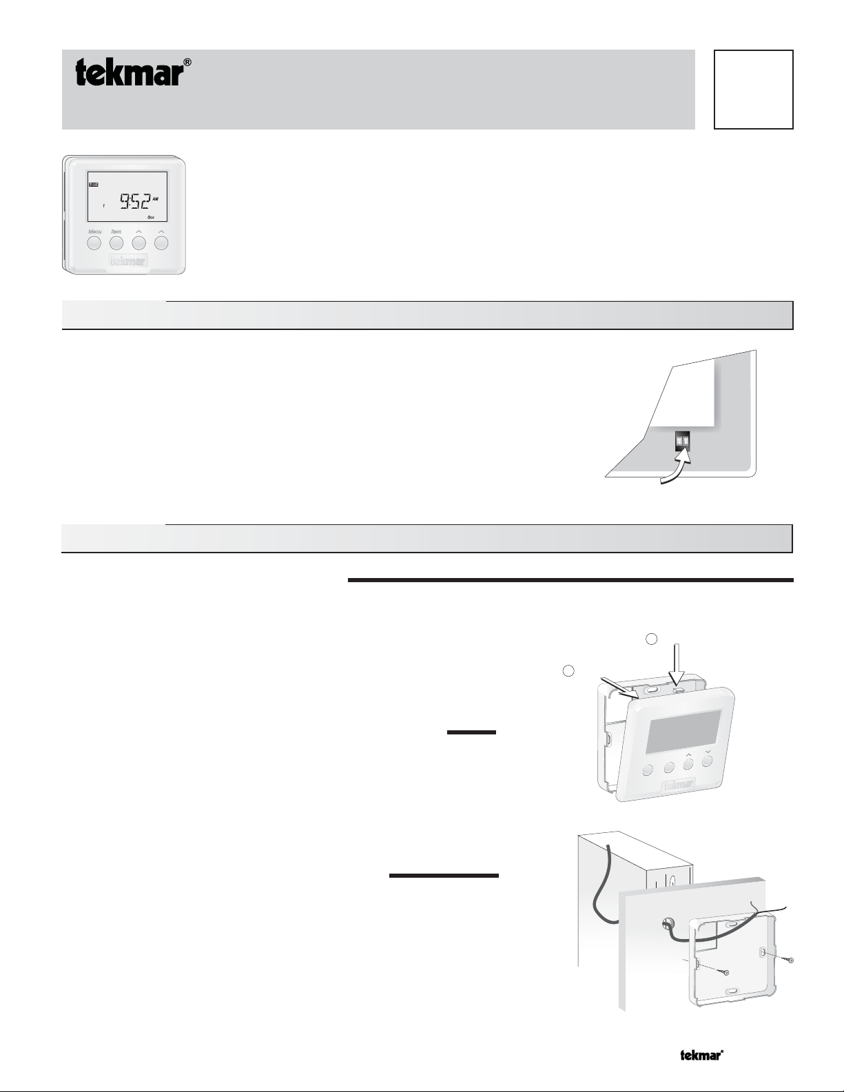
STEP TWO
———————
Place a screwdriver or similar object into the small slot located in the top of
the timer. Push the screwdriver against the plastic tab and pull the top of the
front cover so that it pivots around the bottom edge of the base.
STEP THREE
——————
Mount the base directly to the wall using two #6 1” screws. The screws are
inserted through the mounting holes and must be securely fastened to the
wall. If possible, at least one of the screws should enter a wall stud or similar
surface. If the timer is to be mounted to a 2” x 4” electrical box, order an Adaptor Plate 007. This plate mounts to the electrical box and the timer mounts to
the plate.
GETTING READY
REMOVING THE FRONT COVER
MOUNTING THE BASE
Remove cover
2
M
1
enu
Push tab
Item
#6 1" screws
1 of 4 © 2008 D 032 - 12/08
Page 2

STEP FOUR
———————
ROUGH IN WIRING
• 18 AWG or similar wire is recommended for all 24 V (ac) wiring.
• All wires are to be stripped to ¼” (6mm) to ensure proper connection to the timer.
• Run wires from the 24 V (ac) power to the timer. Use a clean power source to ensure proper operation.
• Run wires from the device to be controlled back to the timer.
34
STEP FIVE
———————
WIRING THE TIMER
Relay
24 V (ac) Power
Connect the 24 V (ac) power to the R and C terminals (1 and 2) of
the timer. This connection provides power to the microprocessor and
display of the timer.
Relay
The Relay terminals (3 and 4) are an isolated output. There is no power
available on these terminals from the timer. This circuit can operate a
low current 24 V (ac) device directly or an external relay to enable a
line voltage or high current device.
STEP SIX
——————
Align the hinges on the bottom of the front cover with the bottom of the
timer mounting base. Pivot the front cover around the bottom hinges and
push the top against the mounting base until it snaps firmly in place.
INSTALLING THE FRONT COVER
24 V (ac)
Class 2
Transformer
1R2
C
Menu
Meets Class B:
Canadian ICES
FCC Part 15
Timer 032
Item
158033
CUS
Relay NC / Relay NO
032
938-08
24 V ± 10% 60 Hz 3 VA
Power:
Relay: 24 V (ac) 2 A
2
Pivot front
cover around
bottom hinges
Align hinges
1
on bottom
of front cover
Settings
SETTING THE TIME
To set the time of day and the day of week, use the following procedure.
Step One: Press and release the
Step Two: Press the
Item
button to set the proper minutes.
Step Three: Press and release the
the
or button to set the proper hour.
Step Four: Press and release the
button to set the proper day.
Step Five: Press and release the
between 12 and 24 hour time.
SETTING THE SCHEDULES
A schedule allows the timer to automatically change between several preset events based on the time of day. The schedule divides
the day into either two or four events. For each event, a different time can be set. To set the time of day at which each event is
to begin, use the following procedure.
Menu
button until the Time Menu is reached.
button. While the minutes are flashing, use the or
Item
button. While the hours are flashing, use
Item
button. While the day is flashing, use the or
Item
button. Use the or button to select
Step One: Press and release the
Step Two: Press and release the
Menu
button until the Schedule (SCHD) Menu is displayed.
Item
button. Use the or button to select the
desired schedule mode. 2 = two events per day (Occ, UnOcc). 4 = four
events per day (Occ 1, UnOcc 1, Occ 2, UnOcc 2).
Step Three: Press and release the
Item
button. Use the or button to select the
schedule, either 7 day or 24 hour.
© 2008 D 032 - 12/08 2 of 4
Page 3

Step Four: Press and release the
Item
button. Use the or button to set the event’s
beginning time. If the event is not required, select the “- - : - -” time. This time is
found between 11:50PM and 12:00AM. Record the event time in the schedule
table found at the bottom of this page for future reference.
Repeat step four until all events have been programmed.
OVERRIDING A SCHEDULE
Either a temporary or permanent override can be selected at anytime. A temporary override is in effect for either 3 hours or until a
different override is selected. A permanent override is in effect until a different override is selected. To select an override, use the
following procedure.
Step One: Press and release the
Step Two: Use the
or button to select the desired override.
Menu
button until the Schedule (SCHD) Menu is displayed.
The timer displays the OVR and Tmpy segments in the display when operating with a temporary override. The OVR and Perm
segments are displayed during a permanent override.
Note: If the None override is selected, the timer uses the programmed schedule.
DISPLAY LIGHTING
The display of the timer has a back light setting. The back lighting can be turned off, turned on or set to operate temporarily for 60
seconds after any button is pressed. To set the operation of the back lighting of the display, use the following procedure.
Step One: Press and release the
Step Two: Press and release the
Step Three: Use the
or button to select the desired back light operation.
Menu
button until the Time Menu is reached.
Item
button until the word LITE is displayed.
Note: If the back light setting is temporary, the first press of a button turns on the back light.
Schedules
FOUR EVENT SCHEDULE
Event
Occ 1
24 Hour
Schedule
Sun
Mon Tues
Wed Thur
Fri
Sat
UnOcc 1
Occ 2
UnOcc 2
TWO EVENT SCHEDULE
Event
Occ
UnOcc
24 Hour
Schedule
Sun
Mon Tues Wed Thur
Fri
Sat
Error Message
E01 The timer was unable to read a piece of information stored in its memory. The timer was required to load the factory settings. The
timer will stop operation until all settings are checked. To clear this error, check all of the settings in the timer.
3 of 4 © 2008 D 032 - 12/08
Page 4

Technical Data
Timer 032
Literature — D 032
Control — Microprocessor-based; This is not a safety (limit) device.
Packaged weight — 0.25 lb. (110 g), Enclosure J, white PVC plastic
Dimensions — 2-7/8” H x 2-7/8 W x 13/16” D (73 x 73 x 21 mm)
Approvals — CSA C US, CSA 22.2 N
Ambient Conditions — Indoor use only, 32 to 122°F (0 to 50°C), < 90% RH non- condensing.
Power supply — 24 V (ac) ±10%, 60 Hz, 3 VA, Class 2
Relay — 24 V (ac) 2 A, Latching, Class 2
The installer must ensure that this control and its wiring are isolated and/or shielded from strong sources of electromagnetic noise. Conversely, this Class B digital apparatus
complies with Part 15 of the FCC Rules and meets all requirements of the Canadian Interference-Causing Equipment Regulations. However, if this control does cause harmful
interference to radio or television reception, which is determined by turning the control off and on, the user is encouraged to try to correct the interference by re-orientating
or relocating the receiving antenna, relocating the receiver with respect to this control, and/or connecting the control to a different circuit from that to which the receiver is
connected.
Cet appareil numérique de la classe B respecte toutes les exigences du Règlement sur le matériel brouilleur du Canada.
Caution The nonmetallic enclosure does not provide grounding between conduit connections. Use grounding type bushings and jumper wires.
Attention Un boîtier nonmétallique n´assure pas la continuité électrique des conduits. Utiliser des manchons ou des fils de accord spécialement conçus pour la mise ·
la terre.
o
24 and UL 873, meets class B: ICES & FCC Part 15
Limited Warranty and Product Return Procedure
Limited Warranty The liability of tekmar under this warranty is limited. The
Purchaser, by taking receipt of any tekmar product (“Product”), acknowledges the terms of the Limited Warranty in effect at the time of such Product sal e and acknowledges that it has read and understands same.
The tekmar Limited Warranty to the Purchaser on the Products sold hereunder is a manufacturer’s pass-through warranty which the Purchaser is
authorized to pass through to its customers. Under the Limited Warranty,
each tekmar Product is warranted against defects in workmanship and
materials if the Product is installed and used in compliance with tekmar’s
instructions, ordinary wear and tear excepted. The pass-through warranty
period is for a period of twenty-four (24) months from the production date if
the Product is not installed during that period, or twelve (12) months from the
documented date of installation if installed within twenty-four (24) months
from the production date.
The liability of tekmar under the Limited Warranty shall be limited to, at tekmar’s
sole discretion: the cost of parts and labor provided by tekmar to repair defects
in materials and/or workmanship of the defective product; or to the exchange
of the defective product for a warranty replacement product; or to the granting
of credit limited to the original cost of the defective product, and such repair,
exchange or credit shall be the sole remedy available from tekmar, and, without
limiting the foregoing in any way, tekmar is not responsible, in contract, tort or
strict product liability, for any other losses, costs, expenses, inconveniences, or
damages, whether direct, indirect, special, secondar y, incidental or consequential, arising from ownership or use of the product, or from defects in workmanship or materials, including any liability for fundamental breach of contract.
The pass-through Limited Warranty applies only to those defec tive Products
returned to tekmar during the warranty period. This Limited Warranty does not
cover the cost of the parts or labor to remove or transport the defective Product,
or to reinstall the repaired or replacement Product, all such costs and expenses
being subject to Purchaser’s agreement and warranty with its customers.
Any representations or warranties about the Products made by Purchaser to its
customers which are different from or in excess of the tekmar Limited Warranty
are the Purchaser’s sole responsibility and obligation. Purchaser shall indemnify and hold tekmar harmless from and against any and all claims, liabilities
and damages of any kind or nature which arise out of or are related to any such
representations or warranties by Purchaser to its customers.
The pass-through Limited Warranty does not apply if the returned Product has
been damaged by ne gligence by persons other than tek mar, accident, fire, Act
of God, abuse or misuse; or has been damaged by modifications, alterations or
attachments made subse quent to purchase which have not been authorized by
tekmar; or if the Product was not installed in compliance with tekmar’s instructions and/or the local codes and ordinances; or if due to defective installation of
the Product; or if the Product was not used in compliance with tekmar’s instruc-
tions.
THIS WARRANTY IS IN LIEU OF ALL OTHER WARRANTIES, EXPRESS
OR IMPLIED, WHICH THE GOVERNING LAW ALLOWS PARTIES TO CONTRACTUALLY EXCLUDE, INCLUDING, WITHOUT LIMITATION, IMPLIED
WARRANTIES OF MERCHANTABILITY AND FITNESS FOR A PARTICULAR
PURPOSE, DURABILITY OR DESCRIPTION OF THE PRODUCT, ITS NONINFRINGEMENT OF ANY RELEVANT PATENTS OR TRADEMARKS, AND ITS
COMPLIANCE WITH OR NON-VIOLATION OF ANY APPLICABLE ENVIRONMENTAL, HEALTH OR SAFETY LEGISL ATION; THE TERM OF ANY OTHER
WARRANTY NOT HEREBY CONTRACTUALLY EXCLUDED IS LIMITED SUCH
THAT IT SHALL NOT EXTEND BEYOND TWENTY-FOUR (24) MONTHS FROM
THE PRODUCTION DATE, TO THE EXTENT THAT SUCH LIMITATION IS
ALLOWED BY THE GOVERNING LAW.
Product Warranty Return Procedure All Products that are believed to have
defects in workmanship or materials must be returne d, together with a written
description of the defect, to the tekmar Representative assigned to the territory
in which such Product is located. If tekmar receives an inquiry from someone
other than a tekmar Representative, including an inquiry from Purchaser (if not
a tekmar Representative) or Purchaser’s customers, regarding a potential warranty claim, tekmar’s sole obligation shall be to provide the address and other
contact information regarding the appropriate Representative.
tekmar Control Systems Ltd., Canada
tekmar Control Systems, Inc., U.S.A.
Head Office: 5100 Silver Star Road
Vernon, B.C. Canada V1B 3K4
(250) 545-7749 Fax. (250) 545 -0650
Web Site: www.tekmarcontrols.com
Product design, software and literature are Copyright © 2008 by:
4 of 4
tekmar Control Systems Ltd. and tekmar Control Systems, Inc.
All specifications are subject to change without notic e.
Printed in Canada. D 032 - 12/08.
 Loading...