

Teac AD-G9320 Owner's Manual
TEAC
Audio/Video
SUlfOund
Receiver
TEAC
~~
O~~I.I.~.
I.I.~~O
C::J
(5
ooo.3S5550e
~
o-o~
~
(5
66
6 :0
(fi
r;~;g;;§;n;~~;;;l
0 @
@=~
OWNER'S
MANUAL
.
Thanks
for
buyingaTEAC.
Read
this
manual
carefullytoget
the
best
performance
from
this
unit
A-·-
A
CAUTION:
TO
REDUCE
THE
RISK
OF
ELECTRIC
SHOCK/DONOT
REMOVE
COVER
(OR
BACK).
NO
USER-SERVICEABLE
PARTS
INSIDE.
REFER
SERVICING
TO
QUALIFIED
SERVICE
PERSONNEL
A
A
The
lightning
flash
with
arrowhead
symbol,
withinanequilateral
triangle,isintendedtoalert
the
usertothe
presenceofuninsulated
"dangerous
voltage"
within
the
producfs
enclosure
that
maybeof
sufficient
magnitudetoconstituteariskofelectric
shocktopersons.
The
exclamation
point
withinanequilateral triangleisintendedtoalert
the
usertothe
presence
of
important
operating
and
maintenance (servicing) instructions
in
the
literature
accompanying
the
appliance.
This
appliance
has
a
serial
number
locatedonthe
rear
panel.
Please
record
the
model
number
and
serial
number
and
retain
them
for
your
records.
Model
number
I
Serial
number
1
WARNING:
TO
PREVENT
FIRE
OR
SHOCK
HAZARD,
DO
NOT
EXPOSE
THIS
APPLIANCE
TO
RAIN
OR
MOISTURE.
IMPORTANT
SAFETY
INSTRUCTIONS
M Note
to
CATV
system
installer:
This
reminderisprovided
to call
the
CA1V
system
instaJler's
attention to Section 820-40ofthe NEe which provides guidelines
for
proper
grounding
and,
in particular, specrries
that
the cable
ground
shall be
connected
to the
grounding
systemofthem
building!asclose
to
the
pointofcable entryaspraetkal.
15}
Lightning-For
added
protection
for
this
product
during
a
lightning storm,orwhen
it is left unattended and unused
for
long
periodsoftime, unplugitfrom the wall
outlet
and disconnect the
antenna
or
cable system.This wi!! prevent
damage
to the
product
due to lightning and power-line surges.
16)
Power
Lines-An
outside
antenna
system
should
not
be
located
in the
vicinity
of
overhead
power
linesorother electric
light
or
power
circuits,orwhere it can fall
into
such
power
lines
or
circuits. When installing an outside antenna system, extreme
care should be taken
to keep
from
touching such
power
lines
or
circuitsascontact
with
them
might
be fatal.
17} Overloading - Do
not
overload
wall
outlets, extension cords,
or
integral convenience receptacles as this can result
in
a risk
of
fireorelectric shock.
18} Object and Liquid
Entry
..
Never push objectsofany kind
into
this
product
through
openingsasthey
may
touch
dangerous
voltage
pointsorshort-out
parts
that
could
result
in a
fire
or
electric
shoc~
Never spill liquidofany
kind on the product.
19)
Servicing·Donot attempt
to
service this
product
yourself
as
openingorremoving
covers
may
expose
youtodangerous
voltage or
other
hazards. Refer all servicingtoqualified service
personnel.
20) Damage Requiring
Service·
Unplug
this
product
from
the
wall
outlet
and
refer
servicingtoqualified
service
personnel
under
the
following
conditions:
a}
When the
power-supply
cordorplug
is damaged.
b}
If
liquid
has
been
spilled,
or
objects
have
fallen
into
the
product.
c}
Ifthe
product
has been
exposed
to rainorwater.
d) If the
product
does
not
operate
normallybyfollowing
the
operating
instructions.
Adjust
only
those
controls
that
are
covered by the operating instructionsasan
improper
adjustment
of
other
controls
may
resultindamage
and
will
often
require
extensive
workbya qualified techniciantorestore the
product
to
its normal operation.
e)ifthe product has been
droppedordamaged in any
way.
f} when the
product
exhibits a
distinct
change in performance-this
indicates
8 need
for
service.
21)
Replacement Parts..When replacement parts are required,
be
sure the service technician has used replacement parts specified
by
the
manufacturerorhave
the
same
characteristicsasthe
original
part.
Unauthorized
substitutions
may
resultinfire,
electric shock,orother
hazards.
22)
Safety Check
..
Upon
completionofany serviceorrepairs to
this
product
ask the service techniciantoperform
safety checks
to determine
that
the
product
is in
proper
operating condition.
23)
Wall or Ceiling
Mounting
- The
product
shouldbemounted
to
a wall
or
ceiLing
onlyasrecommended
by the manufacturer.
24)
Heat-The
product
should be situated
away
from
heat sources
suchasradiators,
heat
registers,
stoves,orother
products
(including amplifiers)
that
produce heat.
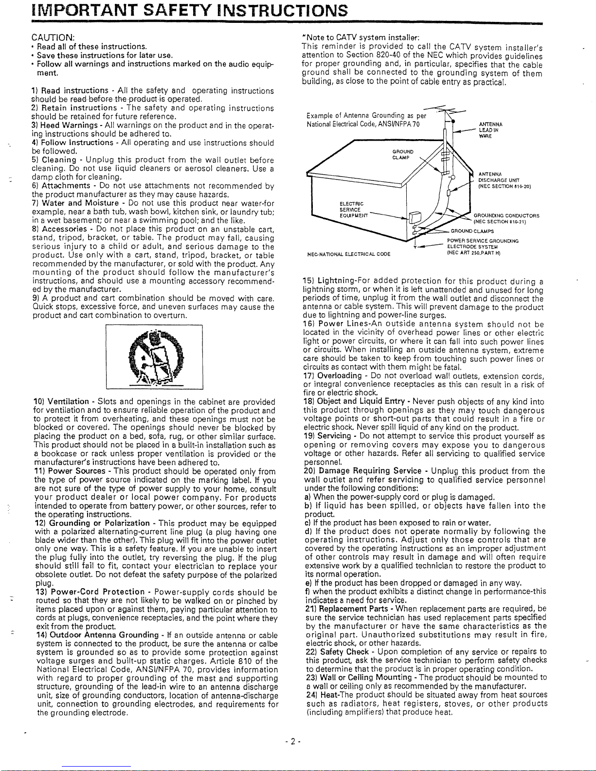
ANTENNA
LEAD
\N
WffiE
ANTENNA
OtSCHAAGE UNIT
(NEe
SECTION 310.20)
MEC-NATIONAl ELECTRICAL CODE
ExampleofAntenna Grounding
as
per
National
Electrical
Code,
ANSVNFPA
70
10}
Ventilation
- Slots and openings in the cabinet are provided
for
ventilation
andtoensure reliable operationofthe
product
and
to
protectitfrom
overheating, and these openings
must
not
be
blocked
or
covered. The
openings
should
never be blocked
by
placing
the
product
on a bed, sofa, rug,orother
sim
ilar
surface.
This
product
should
not
be placed in a built-in installation such
as
a bookcaseorrack unless
proper
ventilationisprovidedorthe
manufacturers
instructions have been adhered to.
11}
Power Sources - This
product
shouldbeoperated
only
from
the
typeofpower
source indicated on the marking
labeL
If
you
are
not
sureofthe
type
of
power
supplytoyour
home,
consult
your
product
dealerorlocal
power
company.
For
products
intendedtooperate
from
battery
power,orother
sources, refer
to
the
operating
instructions.
12)
GroundingorPolarization
-
This
product
may
be equipped
with a polarized alternating-eurrent line plug
(a
plug having one
blade
wider
than the other). This plug
will
fit
into
the
power
outlet
only
one way. This is a safety feature.1fyou
are unable to insert
the
plug
fuBy
into
the
outlet
try
reversing the plug. If the plug
should
still fait
to
fit,
contact
your
electrician
to
replace
your
obsolete outlet. Do
not
defeat the safety purpOseofthe
polarized
plug.
13}
Power-Cord
Protection-Power-supply
cords
should
be
routed so
that
they
are
not
likelytobe walked onorpinched
by
items placed
upon
or
against them, paying particular attention to
cords
at
plugs, convenience receptacles, and the
point
where they
exit
from
the
prod uct.
14)
Outdoor
Antenna
Grounding
-Ifan
outside antennaorcable
system is connected
to
the product, be sure the antennaorcalbe
systemisgroundedsoastoprovide
some
protection
against
voltage
surges
and
built-up
static
charges.
Article
810ofthe
National
Electrical Code,
ANSl/NFPA
70,
provides
information
with
regardtoproper
grounding
of
the
mast
and
supporting
structure,
groundingofthe lead-in
wiretoan
antenna discharge
unit, size
of
grounding
conductors, locationofantenna-dlscharge
unit,
connectiontogrounding
electrodes, and requirements
for
the
grounding
electrode.
CAUTION:
• Read allofthese instructions.
• Save
these
instructions
for
later use.
•
Follow
all
warnings
and instructions marked on
the
audio equip-
ment.
1) Read instructions -
All
the safety and operating instructions
sheukibe
-fea'€iooforethe-pfoduatisG-fJeratee.
2}
Retain
instructions-The
safety
and
operating
instructions
shouldberetained
for
future
reference.
3)
Heed
Warnings
- All
warnings
on the
product
and in the operat-
ing
instructions
shouldbeadhered to.
4)
Follow
Instructions
- All operating and use instructions should
be
followed.
5)
Cleaning-Unplug
this
product
from
the
wall
outlet
before
cleaning. Do
not
use
liquid
cleanersoraerosol cleaners. Use a
damp
cloth
for
cleaning.
6)
Attachments
- Do
not
use attachments not recommended by
the
product
manufacturerasthey
may
cause hazards.
7)
Water
and
Moisture
- Do not use this
product
near water-for
example,
near a bath tub, wash
bowl,
kitchen sink,
or
laundry
tub;
in a
wet
basement;ornear a
swimming
pool; and the like.
8l
Accessories - Do
not
place this
productonan
unstable cart,
stand,
tripod,
bracket,ortable.
The
product
may
fall,
causing
serious
injurytoa
childoradult,
and
serious
damagetothe
product.
Use
only
with
a cart,
stand,
tripod,
bracket,
or
table
recommendedbythe manufacturer,orsold
with
the product.
Any
mountingofthe
product
should
follow
the
manufacturer's
instructions, and
should
use a
mounting
accessory recommend-
edbythe
manufacturer.
9}Aproduct
and cart
combination
should be
moved
with
care.
Quick stops, excessive force, and uneven surfaces
may
cause the
product
and
cart
combination
to overturn.
'-
- 2 •
CONTENTS
IMPORTANT
SAFETY
INSTRUCTIONS
2
PRECAUTIONS
4
CONNECTIONS
5
System
Connections:
, 5
Ceft-nHct1A~the
VH)E·Q
3lNPUT
Jacks 8
Connecting
Antennas I
••••••••••••••••••••••••
8
Connecting Speaker
Systems
9
Connecting
the
AC
Power
9
CONTROLS
AND
INDICATORS
::10
AUDIO
OPERATIONS
,
12
Sleep
Timer
Operation
,.,
,
12
Basic
Operation
12
Audio
Adjustments
13
Radio Reception 14
Preset
Tuning
15
ListeningtoRecords and Compact
Discs
16
Playing MDfTAPE 1 Deck
15-
Playing TAPE 2 Deck
17
Recording a Source , 17
Dubbing
from
TAPE 2
to
MOrrAPE 1
17
VIDEO
OPERATIONS
,
18
Playing Video
Sources
0
••••••••••••••••••••••••
••••••••••••
••
••••••
•••••••••••••••••••••••
18
Recording
withaVideo
Deck
to.
to
18
SURROUND
EFFECTS
19
Avaible
Surround
Modes
19
Speaker
Positioning
20
Speaker
Configuration
20
DELAY
TimelEffect
21
Channel Level
21
Playing
Surround
Sound
,
22
BACK-UP
SySTEM
22
Back-up
Memory
Function
.o
,
••
22
WhentoUse RESET Function ,
22
ABOUT
OSD
(ON
SCREEN
DiSPLAy}
23
REMOTE
CONTROL
UNIT
26
Using
the
Remote
Control
Unit
26
Battery
Installation
,
,26
TEAC
System
Remote-Controlled
Operation
27
Buttons
for
the
OperationofOther
TEAC
Components
, , 28
TROUBLESHOOTING
, , ,
29
SPECiFICATIONS
,
30
- 3 -
PRECAUTIONS
EB.~~;~::rfi~~:~~f~:E~:qp2~~~In~·~~~;41~):9~1:;1d1;tl;:
>;i
.•
:C.~·,:-~,
• Choose the installation location of your unit carefully.
Avoid
placing it in direct
sunlight
or close to a source
of
heat.
Also
avoid
locations
subject
to
vibrations
and
QXGe"ssh/ed-lJ~trhBat,
coldor-moistu-r::a.
• The ventilation holes should not
be
covered.
Make
sure
there
isatleast10em(4inches) of
space
above
and
at
least10em(4inches)ofspace beside the
amplifier/receiver.
Do
not place a
CD
player or other
equipmentontopofthe amplifier/receiver.
• Do
not
open the cabinetasthis
might
result in damage
to
;-
the
cirCUITry
or electrical shock.
Ifaforeign
object
should
get into the
set
contact your dealer.
• When
removing
the
power plug
from
the
wall outlet,
always pull directly on the plug, never yank the cord.
•
Do
not attempt
to
clean the
unit
with
chemical solvents
as
this
might
damage the finish. Use a clean, dry cloth.
• Keep this manual in a safe place
for
future
refernce.
CAUTION Regarding
Placement
To
maintain
proper
ventilation,
be sure
to
leave a
space around
the
unit
(from the largest outer
dimensions including projections) equal to, or
greated
than,
shown
below:
Left and
right
Panels: 10cm
Rear Panel : 10cm
Top
Panel : 10cm
- 4 -
For
U.S.A-------------
TO
THE
USER
This
equipment
has been tested and found to
comply
with
the
limits
for
a
A/V
receiver,
pursuant
to
Part
15
of
tbe
FCC
BuIes.
Ih,Hs-eJjmjts~Je
.d-esi9J1ad
to provide reasonable protection against interference
in a residential area. This
device
generates
and~uses
radio
frequency
energy and
if
not
installed and
-used
in
accordance
with
the
instructions,
if
may
cause
interferenee
torad
io
or
TV rece pti
on.
If
this
unit
does cause interference
with
TV
or
radio reception
you
can
trytocorrect
the
interference
by
one
or
more
of the
following
measures:
a)
Reorient or relocate the receiving antenna.
b) increase
the
separation between the
equipment
and the receiver.
c)
Plug the
equipment
into a different outletsothat
it
is
not
on
the same
circuit
as
the
receiver.
If
necessary,
consult
the
dealeroran
experienced
r
ad
i
orrv
tee
hn
Lci
an for
add
it
ionaI s
ug
9estion
s.
CAUTION
Changesormodifications
to
this
equipment
not
expressly
approved
by
TEAC CORPORATION
for
compliance
could
void
the user's authority to
operate
this
equipment.
The
equipment
draws
nominal
non-operating
power
from
the
AC
outlet
with
its
POWER
switch in
the
STANDBY
position.
Obs{
natstromstallarenskiljerejhela apparaten
fran natet.
For
CANADA
-------------,
AC
POWER
CORD
CONNECTION
CAUTION:
TO PREVENT ELECTRIC SHOCK,
MATCH
WIDE
BLADE
OF
PLUG TO WIDE SLOT, FULLY INSERT.
PourIeCANADA----------,
CORDONDECONNEXION
CA
ATIENTION:
POUR
EV1TER
LES
CHOCS
ELECTRIQUES/
INTRODUIRE LA LAME LA
PLUS
LARGE
DE
LA
FICHE
DANS LA
BORNE
CORRESPONDANTEDELA
PRISEETPOUSSER JUSQU'AU FOND.
CONNECTIONS
~
To
WALL
outlet
'M'!AI
~
WtAt
~
......
@l
~""""',€)-R
t t
R.::
fQd
t
RaQ
Tape
Deck
'WtlI!I
J
L @...-.
R@~c::::SIt~l-~
Left
Right
Front A Speaker
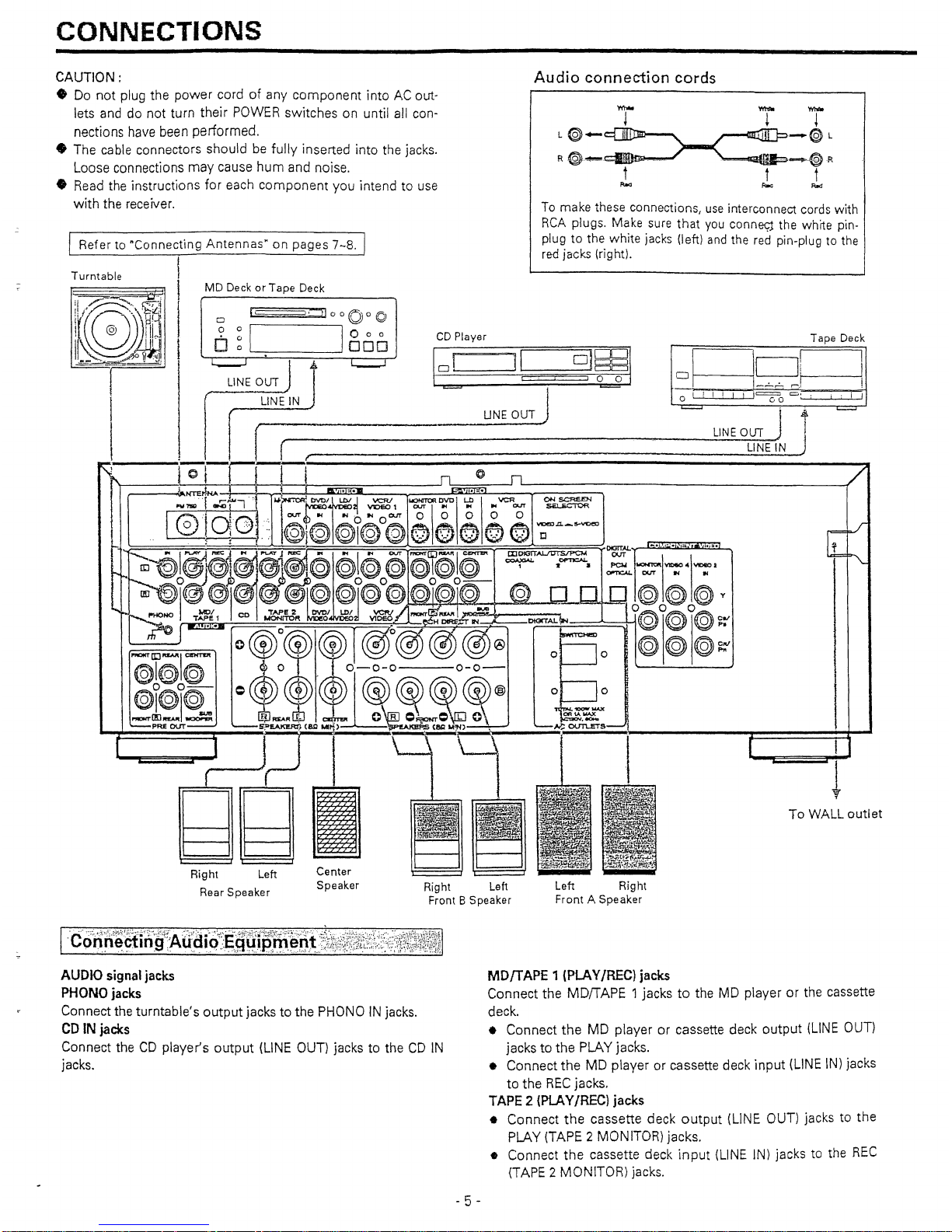
To make these connections,
use
interconnect cords
with
RCA
plugs.
Make
sure that
you
conne<;j the whrte pin-
plugtothe
white
jacks (left)
and
the red pin-plug to the
red jacks (right).
Audio
connection
cords
CD
Player
Right
Left
Front 8 Speaker
Center
Speaker
[l
o
o
Right Left
Rear
Speaker
I . f . (
L1N
i
'N
~
:__
UNEOUT
J I
~ljL:~J
=J
i·
I I
\
lo'-q-11'
. j t .
f_l
I
II
f
~
J
~~{~HA
r-~
..
....,
...,...
~~ij'
J.
VCR!
UONrTOROVDI
~-·I
VCR
~,~
I'V'l"Sl)
-.c:l
I I
t>~
4 V1DE01
OUT
1M
1M
...
OIJT
~I-.rn.
L~..e~Q:
l@!@
@I@O@
6\0
066
~.._~~
I
~~,@I~@t@1@l.l';i@.~.~~.I@@@.I@."I@
~~.
l!£l~I~.IH04IVC:2
o~
Ji)~
SrJ~
0 0 0
0-
UD-oI@)@I'Q,
~~I~~O
@~@@
0 0
ro.....
0
0_
o@o@o@y
. f-HONO
MOl
co
"TAPE 2
DVDI
UJ/
VCPV
/I~retlUM
,
l~
~
~
~
ri5fEf:J..
MONtTOfI
0
V1"",::L£:\'!--'H
OtREZT
IN-'''--t>I<I<TAL(lN
~
~
~
~
_~JCOKTm
Q@)Oev
~
[@r®®0.@06
0
@@@~~
@I@k~
~
0
'.
0-0-0
0-0-
@1@O@am
=~
(1)
?~@~)(G))@)®
°oo~':
=:~R£J~
~~(811~
Q~~
'0\.
F~s
/
J~LJ
9
~
Inn
I
.1
BB
~.BLI~
RefertonConnecting
Antennas"
on pages
7-8.
!
Turntable
I
I i
MD
Deck
or Tape Deck
j
i
CAUTION:
• Do not plug the
power
cord
of
any
component
intoACout-
lets and do
not
turn their POWER switches on until all con-
nections
have
been
performed.
•
The
cable connectors should
be
fully
inserted into the
jacks.
Loose connections
may
cause hum and noise.
• Read the instructions
for
each component you intend to use
with the receiver.
1··Co·nri'~~i·riltAti:~
i9::$Jr~.trn;~~~J~t~t~iW~tfA';,::~:+~:i};~±i~)t~V~!1
AUDIO
signal
jacks
PHONO
jacks
Connect
the turntable's outputjacks to the
PHONOINjacks.
CD
IN
jacks
Connect theCDplayer's output
(LINE
OUT) jacks to the
CD
IN
jacks.
MD/TAPE 1(PLAY/REe) jacks
Connect the
MDIT
APE
1jacks
to
the
MD
playerorthe cassette
deck.
• Connect
the
MD
playerorcassette deck output
(LINE
OUT)
jacks to
the
PLAY
jacks.
•
Connect
the
MD player or cassette deck input
(LINE
iN) jacks
to the
REC
jacks.
TAPE
2 {PLAY/REel jacks
• Connect
the
cassette deck
output
(LINE OUT) jacks to the
PLAY
(TAPE
2
MONITOR)
jacks.
• Connect the cassette deck
input
{LINE
IN) jacks
to
the
REC
(TAPE
2 MONITOR) jacks.
- 5 -
I.
'C
0 Q
n,epti
f.l
g'
.¥i
dep,:E
qu
ipm-erit:'2iti~1itJ~Y£i;~f;~:b';i%i~~tI;1
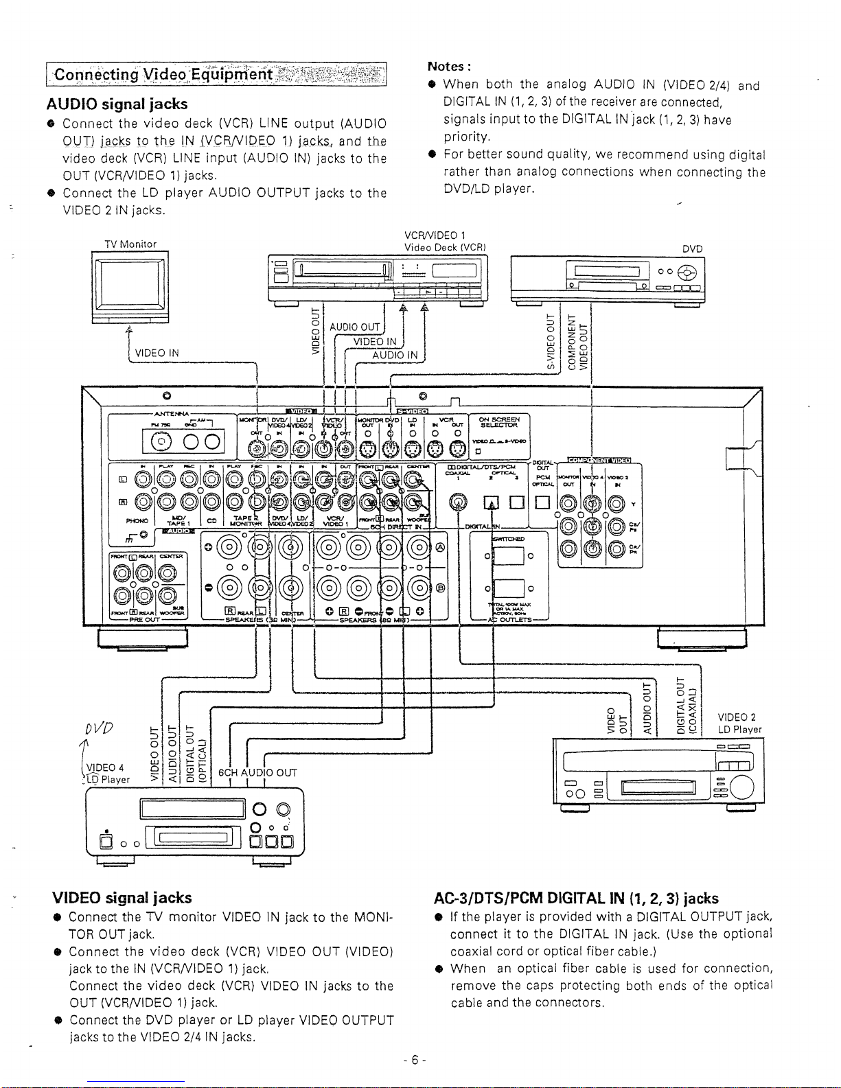
AUDIO
signal jacks
• Connect the
video
deck
(VCR)
LINE output (AUDIO
OVI)
J.QGKS
19
th~
tN
JVCRNIPEO
1}
lacks!
and
th.e
video deck
(VCR)
LINE
input
(AUDIO
IN)
jacks to the
OUT
(VCRN1DEO 1)
jacks.
•
Connect
the
LD
player
AUDIO
OUTPUT
jackstothe
VIDEO 2 IN
jacks.
Notes
:
•
When
both
the
analog
AUDIO
IN {VIDEO 2/4}
and
D1GfTAL
IN
(1,2/
3)ofthe
receiver
are
connected,
signals
input
to the DIGlTALIN'jack
(1,2,3)
have
priority.
• For
better
sound quality, we
recommend
using
digital
rather
than
analog
connections
vvhen
connecting
the
DVD/LD
player
.
TV
Monitor
o
iVIDEO IN
\.
e
@I@I@
00-
@\@j@..,.
~(HJPt£AA
'NOOl"'l:R
PRE
OUT
VCRIVIDEO
1
Video
Deck (VCR)
Dva
Ir:=-·=p~
~'~I
I~'
II~!!
~i
I~===ll~i
II
I Q
Q~7§1
• 1
c:=::J
t
~
~
t-
f
~
z~
o UJ::>
o
zol
UJ
0
010..
0
'v
~J8~1
o
II
tlo
Q
Cooll
'
1\1800
t::I
c::c::J
6[
]~
DVO
1
VIDEO
4
~tQ.
Player
~1~1~
6161S~
o
O.
<t u
w
5}1--
Qj
~
Q
to'
6CH
AUDIO
OUT
>
<i:1
0 _
.1-
~
~
o 0
WI-
C5
a::>
:::>
>0
«
t-
6:J
-1«
<ex
E
~
I
VIDEO
2
CS
k?
LD
Player
VIDEO
signal jacks
•
Connect
the
TV
monitor
VIDEO
IN
jacktothe
MONI-
TOR
OUT
jack.
•
Connect
the
video
deck
(VCR)
VIDEO
OUT
(VIDEO)
jacktothe
IN
(VCRN1DEO
1)
jack.
Connect
the
video
deck
(VCR)
VIDEOINjackstothe
OUT
(VCRNIDEO1)jack.
•
Connect
the
DVD
playerorLD
player
VIDEO
OUTPUT
jackstothe
VIDEO
2/4 IN
jacks.
- 6-
AG-3/DTS/PCM
DIGITAL
IN
(1,
2,3)jacks
•Ifthe
playerisprovided
withaDIGITAL
OUTPUT
jack,
connect it to the DIGITALINjack.
(Use
the optional
coaxial
cordoroptical
fiber
cable.)
•
When
an
optical
fiber
cableisused
for
connection,
remove
the
caps
protecting
both
endsofthe
optical
cable
and
the
connectors.
CONNECTIONS
I·
ConneCti.llgth
e';
PREOQ"rif
acks'~7q*t,i~;J~Wi.~!J~~~E~~1
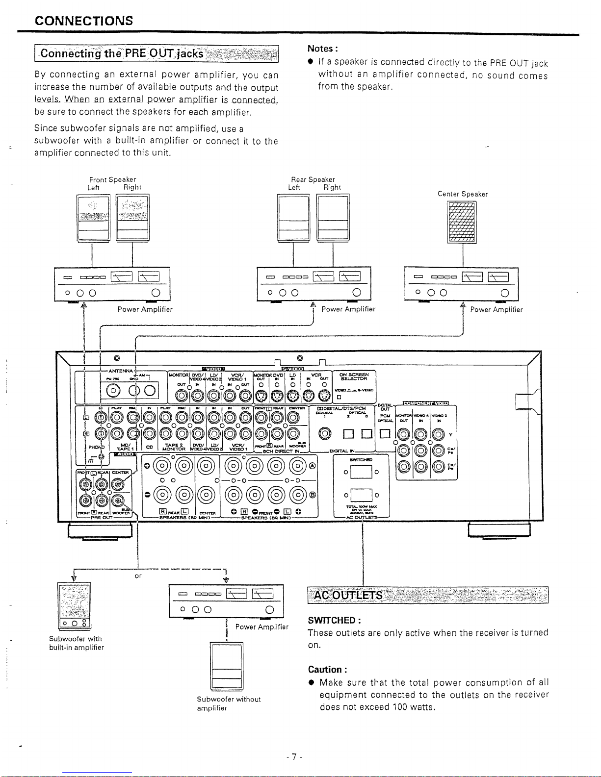
Bye
0 nnectin9 a
next
ern
aI power
amp
I
if
ierI
you
can
increase the number of available outputs
and
the output
leY.eLs.~Wh_enaoe.xtern.gJ
J)
QVYeram.pLifieJ
Ls
.c.Q.onected
l
be
suretoconnect
the
speakers
for
each amplifier.
Since
subwoofer
si gnals are
not
amplifiedruse a
subwoofer
with
a built-in
amplifier
or connectitto the
amplifier
connectedtothis
unit.
Notes :
• If a speakerisconnected directlytothe
PRE
OUT jack
without
an
amplifier
connected/
no
sound
comes
from
the speaker.
000
Front
Speaker
Leh Right
I
Center
Speaker
c:::J
c:::;:::Jt::JO
ts=:l
ts=J
000
0
Rear
Speaker
Left Right
~
~
I
I
c:::J
c=:c:JCJO
[E
[E
000
0
r:;:J
e::t::JCJCJ
[E]
B
o
ck
t·
Power Amplifier
I
J
,--------"
~
i
Power
Amplifier -
1"
Power
Amplifier
I )
I r
r~---------------'
~f-Iel
n@n
I
~~-ANTENNA
t 10 • •
::l_
D
ll
I
~
d1~
~~o'fti~:.r
~1
°r\
;I
;vc~
C:~
! ·0
PQ
@I@I@I@
@ @
000
0
;""'"~""'"
DKlfT"-
~...
•
•••
~~
$I@@I@
@
@I@~;
I@@
@I@I@
~~3
~
,,::"llw:o"l~a
~.I··
@)o\@Ool@@o@I@@I@o@@I@ol@@DDD@@@Y
r
1.<01
I
TAPE'
~
LD/J
YCRI
_rID
__
~
o@O((2t@
.ii~E.'.
:@7@@r@0@@@®
~:Eso
@\@!@:
$1$1
. 0 0
0-0-0
0-0-
@1~01&
=@@@I@@@@®o=g_o
~~~"""""J)
~=I",,':~~~~Ja
0
..:~_
r
r
~
~
Subwoofer
with
built-in
amplifier
or
....
__
...
_-_
...
_,
T
=
~cc661
000
0
- IPower
;;plifier
,
~
=
Subwoofer
without
amplifier
1%~giQ'Q;;[g§t~;:;~t~i~~~ttiti~~t~~i~~~1;f;'~'i~i~R~li;[~~i~:~';;:;':i~,::i~J.~~,t;Mli~;!~1
SWITCHED:
These outlets are
only
active
when
the receiver
is
turned
on.
Caution :
• Make sure
that
the
total
power
consumptionofall
equipment
connectedtothe
outlets
on the receiver
does not exceed 100 watts.
- 7 -
1-
Ccirin~Ct~n
iftheVlD
E
Q:-3J
NPUTJ
~icks::):t:::li.:::l
[
FM
Outdoor
Antenna
""'-A),A,
~bOj
ANTENNA
Outdoor
FM Antenna (750)
.-
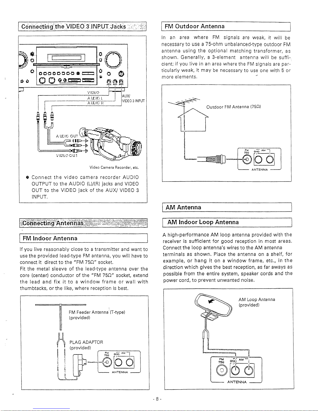
In an area
where
FM
signals
are
weakrit
will
be
necessary to
use
a75-ohm unbalanced-type outdoor
FM
antenna
using
the
optional
matching
transformer,
as
shown.
Generally,a3-element
antenna
witl
be
suffi-
..
cient;ifyou
liveinan area
where
the
FM
signals
are
par-
ticularly
weak{itmay
be
necessary
to
use
one
with5or
more
elements.
1 \ I
\fIDH!
~
. ...J
ALUC
H
!
~
-
~
rr--~~-TJ
~
0 I
o
00000000.
t::I::l 0 0
at>
Ii
o 0
'$r:=tr=:J
~~..~n
11';'
I I
Video Camera Recorder, etc.
•
Connect
the
video
camera
recorder
AUDIO
OUTPUTtothe
AUDIO
(l)!(R) jacks and VIDEO
OUTtothe
ViDEO
jackofthe
AUX/
VIDEO 3
INPUT.
[
AM
Antenna
~(P&~tlQ;ctirig'rA'htg~[~~;tt~~ttI~;~7f'~~~;~~~~1~i~~~~~~~f~
IFM
Indoor
Antenna
If
you
live
repsonably
closetoa
transmitter
and
want
to
use
the
provIded
lead-type
FM
antenna,
you
will
have
to
connectitdirecttothe
IlFM
75(r'
socket.
Fit
the
metal
sleeve
of
the
lead-type
antenna
over
the
core (center)
conductorofthe
"FM
750"
socket,
extend
the
lead
and
fixittoawindow
frame
or
wall
with
thumbtacks,
or
the like,
where
reception
is best.
I
AM
Indoor
Loop
Antenna
A
high-performance
AM
loop
antenna
provided
with
the
receiverissufficient
for
good
reception
in
most
areas.
Connect the
loop
antenna's
wirestothe AM
antenna
terminals
as
shown.
Place
the
antenna
onashelf,
for
example
r
or
hangiton a
window
framer
etc., in
the
direction
which
gives the best reception,asfar aways
as
possible
from
the entire
system,
speaker
cords
and the
power
cord,toprevent
unwanted
noise.
FM Feeder Antenna' (T-type)
(provided)
f~
PLAG
ADAPTOR
I (provided)
~
Wf
~
ofo
AM
=l
~'
w_@[o
q
\
t.
ANTENNA
~_
...
,J
AM
Loop Antenna
(provided)
I
LMb
"'==~-l
ib=r~~~,
~
FM
,..
....
AM-,
@~6J
ANTENNA
- 8 -

CONNECTIONS
I
AM
Outdoor
Antenna
Ifthe
AM
loop antenna provided does not deliver
sufficient
reception
{because
you
are
too
far
from
the
transtnTfter
or
inaconcrete
bunding,
etc.L
it
may
be
necessary
to
use
an
outdoor
AM
antenna.
Use
an
insulated
wire
more
than
15ft(5m)longIstrip
one
end,
and
connect
thistothe
terminalasshown.
The
antenna
window.
For
better
reception,
connect
theGND
terminal
to a
reliable
ground.
Note:
Even
when
usinganoutdoor
AM
antenna,donot
disconnect
the
AM
loop
antenna.
1'~'GQ~h~Cti
ng'Speake{c$yst
ems,~,,:,)}:',i';;}:-;;"';!;;:1':~
Caution:
To
avoid
damage
the
speakers
by
inputtingasudden
hig'h
..
tevtri slgncrl,be
suretoswitch
the
power
off
before
connecting
the
speakers.
Connect
the
cable
from
each
speakertott}e
corresponding
terminal
on
the
rearofthe
receiver.
•
Most
speaker
cables
have
different
markings,
textures
or
colorstohelp
you
tell
the
difference
between
negative
and
positive.
•
Be
suretoconnect
the
positive
(+)
terminal
on
each
speakertothe
positive
(+)
terminal
on
the
receiver.
S
imil
arly,
con
nectthe
negative
(-)
te
rm
inal
on
the
speakertonegative
(-)
terminal
on
the
receiver.
AM
Outdoor
Antenna
~
GND
AM
=1
@[9(j
i
~
AN'~ENNA
~
rh
I
f.
't
J
••••••••
~
I
. -
..
-
- 9 -
Notes:
• Use
speakers
withanominal
impedanceof8
ohrns
or
more.
•
When
using
the
rear
speakers,
be
suretoconnect
themtoboth
channels
(L and R).Ifa speaker is
con-
nectedtoonly
one
channel,nosound
will
be heard.
•
Howtoconnect
(1)
Strip
back
the
cable
covering
by
a
bout
1 cm
and
twist
the
wire
strands
together.
(2)
Turn
the
terminal
cap
counterclockwisetoloosen
it.
The
speaker
terminal
caps cannot be fully removed
from
the
base.
(3)
Insert
the
wire
into
the
terminal
fully
and
turn
the
terminal
cap
clockwisetosecurely
connect
it.
(4)
Make
sureitis
fastened
firm
by
pulling
the
cable
Jightly.
I
&1
r8g:~a!i~~ingR6~:~gre~~~r:i~~~}~~f,~l:~NJit~;$,~&j:!i~tJ~f$~;~t~fil
Be
sure to connect the
power
cordtoan AC
outlet
which
supplies
the
correct voltage.
•
Hold
the
power
plug
when
plugging
or
unplugging
the
power
cord.
 Loading...