


L40E5800US

TCL
SERVICE MANUAL
L40E5800US/RT95L-AP
1. Caution……………………………………………………………
2. specification…………………………………………………………
3. Alignment Procedure…………………………………………………
4.Block diagram……………………………………………………………
5.Scheme Diagram …………………………………………………………
6. Troubleshooting………………………………………………………………
([SORGHGUDZLQJ
This m anual i s t he l atest at t he t ime of pr inting, and doe s not
include the modification which may be made after the printing, by
the constant improvement of product
RISK OF
ELECTRIC
SHOCK DO
NOT
OPEN.
SCHNEIDER ELECTRONICS GMBH-GERMANY
1. CAUTION
CAUTION:
Use of controls, adjustments or procedures other than those specified herein may result in
hazardous radiation exposure.
CA UT ION : TO RE DU CE THE RIS K OF
CA U T IO N
RISK
SHOCK
The lighting flash with arrowhead symbol, with an equilateral triangle is intended to
alert the user to the presence of uninsulated voltage within the products
enclosure that may be of sufficient magnitude to constitute a risk of electric shock to
the person.
The exclamation point within an equilateral triangle is intended to alert the user to the
presence of important operating and maintenance (servicing) instructions in the
literature accompanying the appliance.
ELECTRI
NOT
OPEN.
ELECTR ICAL SHOCK, DO NOT RE MOVE
COVER (OR BACK). NO USER SERVIC EA BLE
PAR TS INS IDE . RE FE R SER VIC ING TO
QUALIFIE D SERVICE PERS ONNEL.
dangerous
WARNING: TO REDUCE RISK OF FIRE OR ELECTRIC SHOCK, DO NOT
EXPOSE THIS APPLIANCE TO RAIN OR MOISTURE.
2

SCHNEIDER ELECTRONICS GMBH-GERMANY
IMPORTANT SAFETY INSTRUCTIONS
CAUTION:
Read all of these instructions. Sa ve these instructions f or later use . Follo w all Warnings and
Instructions marked on the audio equipment.
1. Read Instructions-All the safety and operatinginstructionsshouldbe read beforethe productis operated.
2. Retain Instructions- The safety and operating instructions should be retained for future reference.
3. Heed Warnings- All warnings on the product and in the operating instructions should be adhered to.
4. Follow Instructions- All operating and use instructions should be followed.
FOR YOUR PERSONAL SAFETY
1. When the power cord or plug is damaged or frayed, unplug this television set from the wall outlet and refer servicing to
qualified service personnel.
2. Do not overload wall outlets and extension cords as this can result in fire or electric shock.
3. Do not allow anything to rest on or roll over the power cord, and do not place the TV where power cord is subject to
traffic or abuse. This may result in a shock or fire hazard.
4. Do not attempt to service this television set yourself as opening or removing covers may expose you to dangerous
voltage or other hazards. Refer all servicing to qualified service personnel.
5. Never push objects of any kind into this television set through cabinet slots as they may touch dangerous voltage
points or short out parts that could result in a fire or electric shock. Never spill liquid of any kind on the television set.
6. If the television set has been dropped or the cabinet has been damaged, unplug this television set from the wall outlet
and refer servicing to qualified service personnel.
7. If liquid has been spilled into the television set, unplug this television set from the wall outlet and refer servicing to
qualified service personnel.
8. Do not subject your television set to impact of any kind. Be particularly careful not to damage the picture tube surface.
9. Unplug this television set from the wall outlet before cleaning. Do not use liquid cleaners or aerosol cleaners. Use a
damp cloth for cleaning.
10.1. Do not place this television set on an unstable cart, stand, or table. The television set may fall, causing serious injury
to a child or an adult, and serious damage to the appliance. Use only with a car t or stand recommended by the
manufacturer, or sold with the television set. Wall or shelf mounting should follow the manufacturer s instructions, and
should use a mounting kit approved by the manufacturer.
10.2. An appliance and cart combination should be moved with care. Quick stops, excessive force, and uneven surfaces
may cause the appliance and cart combination to overturn.
3
3
SCHNEIDER ELECTRONICS GMBH-GERMANY
PROTECTION AND LOCATION OF YOUR SET
11. Do not use this television set near water ... for example, near a bathtub, washbowl, kitchen sink, or laundry tub, in a
wet basement, or near a swimming pool, etc.
Never expose the set to rain or water. If the set has been exposed to rain or water, unplug the set from the wall
outlet and refer servicing to qualified service personnel.
12. Choose a place where light (artificial or sunlight) does not shine directly on the screen.
13. Avoid dusty places, since piling up of dust inside TV chassis may cause failure of the set when high humidity persists.
14. The set has slots, or openings in the cabinet for ventilation purposes, to provide reliable operation of the receiver, to
protect it from overheating. These openings must not be blocked or covered.
Never cover the slots or openings with cloth or other material.
Never block the bottom ventilation slots of the set by placing it on a bed, sofa, rug, etc.
Never place the set near or over a radiator or heat register.
Never place the set in enclosure, unless proper ventilation is provided.
a built-in
PROTECTION AND LOCATION OF YOUR SET
15.1. If an outside antenna is connected to the television set, be sure the antenna system is grounded so as to provide some
protection against voltage surges and built up static charges, Section 810 of the National Ele ctrical Code, NFPA No.
70-1975, provides information with respect to proper grounding of the mast and supporting structure, grounding of the
lead-in wire to an antenna discharge unit, size of grounding conductors, location of antenna discharge unit, connection
to grounding electrode, and requirements for the grounding electrode.
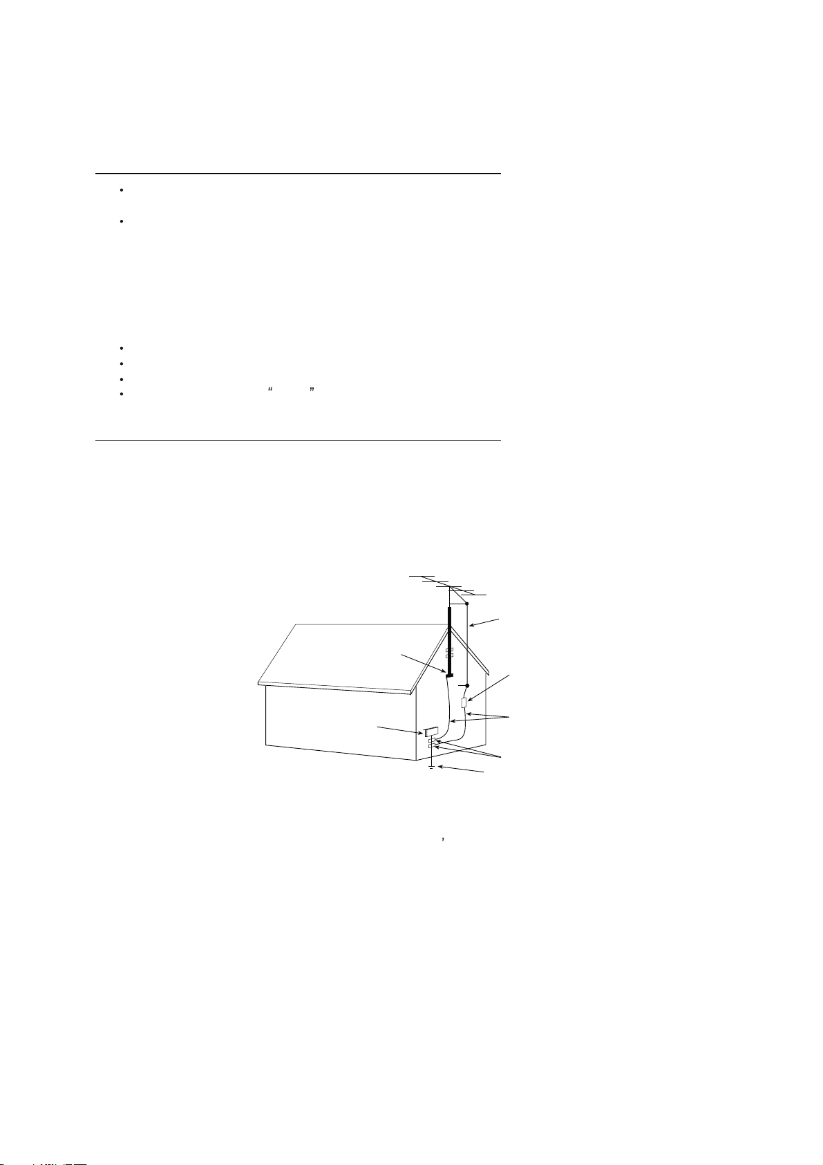
EXAMPLE OF ANTENNA GROUNDING AS PER NATIONAL ELECTRICAL CODE INSTR UCTIONS
EXAMPLE OF ANTENNA GROUNDING AS PER
NATIONAL ELECTRICAL CODE
ANTENNA
LEAD- IN WIRE
GROUND CLAMP
ELECTRIC SERVICE
EQUIPMENT
NEC-NATIONAL ELECTRICAL CODE
ANTENNA DISCHARGE
UNIT (NEC SECTION
810-20)
GROUNDING
CONDUCTORS
(NECSECTION 810-21)
GROUND CLAMPS
POWER SERVICE GROUNDING
ELECTRODE SYSTEM
(NEC ART 250. PART H)
15.2. Note to CATV system installer : (Only for the television set with CATV reception)
This reminder is provided to call the CATV system attention to Ar ticle 820-40 of the NEC that provides
installer s
guidelines for proper grounding and, in particular, specifies that the cable ground shall be connected to the grounding
system of the building, as close to the point of cable entry as practical.
16. An outside antenna system shouldnot be located in the vicinity of overhead power lines or other electric lights or power
circuits, or where it can fall into such power lines or circuits. When installing an outside antenna system, extreme care
should be taken to keep from touching such power lines or circuits as contact with them might be fatal.
17. For added protection for this television set during a lightning storm, or when it is left unattended and unused for long
periods of time, unplug it from the wall outlet and disconnect the antenna. This will prevent damage due to lightning
and power-line surges.
4
4

SCHNEIDER ELECTRONICS GMBH-GERMANY
OPERATION OF YOUR SET
18.
This television set should be operated only from the type of power source indicated on the marking label.If you are not
sure of the type of power supply at your home, consult your television dealer or local power company. For television
sets designed to operate from battery power, refer to the operating instructions.
19. If the television set does not operate normally by following the operating instructions, unplug this television set from the
wall outlet and refer servicing to qualified service personnel. Adjust only those controls that are covered in the operating
instructions as improper adjustment of other controls may result in damage and will often require extensive work by a
qualified technician to restore the television set to normal operation.
20. When going on a holiday : If your television set is to remain unused for a period of time, for instance, when you go on
a holiday, turn the television set and unplug the television set from the wall outlet.
off
IF THE SET DOES NOT OPERATE PROPERLY
21. If youare unable to restorenormal operation by followingthe detailedprocedurein youroperating instructions,
do not attempt any further adjustment. Unplug the set and call your dealer or service technician.
22. Whenever the television set is damaged or fails, or a distinct change in performance indicates a need for
service, unplug the set and have it checked by a professional ser vice technician.
23. It is normal for some TV sets to make occasional snapping or popping sounds, particularly when being
turned on or off. If the snapping or popping is continuous or frequent, unplug the set and consult your
dealer or service technician.
FOR SERVICE AND MODIFICATION
24. Do not use attachments not recommendedby the television set manufacturer as they may cause hazards.
25. When replacementparts are required, be sure the service technician has used replacementparts specified
by the manufacturer that have the same characteristics as the original part. Unauthorized substitutions
may result in fire, electric shock, or other hazards.
26. Upon completion of any service or repairs to the television set, ask the service technician to perform
routine safety checks to determine that the television is in safe operating condition.
5
5
Product Type
LCD Smart TV
Music MP3/WMA
Chassis
RT95L-AP
Picture JPEG/BMP/PNG/GIF
CPU Dual Core A9 1.2GHz
MPEG-(1/2/4)/H.264/H.263
GPU Quad Core IMG544
VC1/VP6/VP8/WMV/DIVX
OS Android 4.2
Memory 12Gb DDR3 / 8GB Flash File No
UI Style Cross UI
OSD Language
English, Arabic, Hebrew, Farsi, Russian,
French, Uzbekistan
PAL B/G、D/K、I Component Video Format YPBPR:up to 1080P
DVB-T、DVB-T2 DVI Video Format Up to XGA for HDMI-PC
AV System
PAL、NTSC
USB Video Format Standard
Channels
000-999
HDMI Video Format up to 2160P
Power Supply
AC 100V-240V 50/60Hz
PC Compatibility Up to SXGA
Power Consumption(TV On)
100W
Power Consumption(Standby)
≤0.5W
Certification
CB Backlight Unit
DLED
Energy Efficiency Level 5
Panel supplier TCL(SDC O/C)
Wired Network Default Aspect Ratio 16:9
Built in wireless module(2T2R 802.11n 300Mbps)
Panel Size (inch) 40"
LED Indicator Status Center of Front,White on Standby Display Resolution UHD(3840x2160)
Brightness (cd/m2) 320(typ.)
Contrast Ratio 5000:1 (Typ.)
Auto Source
Auto、Close、Manual Response Time Typ.8ms
PVR Coming soon
Viewing Angle (H/V)
Typ.178°/Typ.178°(CR≥10)
TimeShift Coming soon
Life Time(Typ.) 30,000hrs
Blue tooth
No
Color 1.07B (Dithered 10bit)
CEC No
Refresh Rate
50/60Hz(4k2k) V by 1
EPG
Yes(Only DTV)
Subtitle Yes (Only DTV)
Parental Control Yes
Sleep Timer Yes
System Update from Internet or USB Yes
Hotel Mode Coming soon
Input Method Smart TV IME
MHL Yes
Teletext No
Nicam No
Lightsensor No
3DTV Type No
3D Display No
3D Format No
Natura Light Technology
Normal、Dynamic、Off
DCC(Dynamic Contrast Control) On/Off
Backlight Adjustable Yes (0~100)
Color Temperature
Normal、Cold、Warm
Picture Mode
Normal、Vivid、Mild、User
Picture Size
Auto、16:9、4:3
Gamma Adjustable
-4 to 4
Comb Filter 3D
Dynamic Noise Reduction 3D
Adaptive Deinterlacing 3D
Motion Compensation Yes
Black Stretch Yes
DLTI Yes
DCTI Yes
Dynamic Skin Correction Yes
Super Resolution UHD 3840x2160
PRODUCT SPECIFICATION RELEASE
Model: L40E5800US/RT95L-AP(ISC)/LVU400NDEL SD9W00 V5
Version:V2.0 Issued On: 2015-03-12
Internet Link
Video
TV System
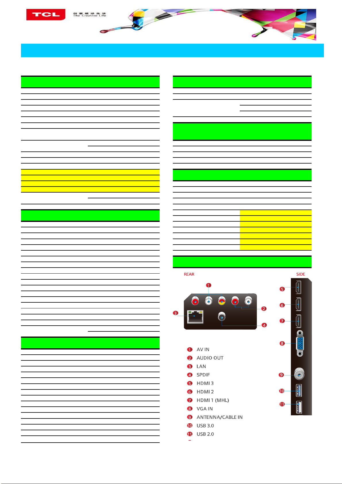
Terminals
Picture
USB Device Media Format
Signal Format Capability
Panel Specification
Basic Information
Basic Function
Speakers Integrated speakers (Bottom side)
Audio Power Output(THD=7%) 2×8W
Smart Volume On / Off
Smart Audio
Normal、Music、Movie、News
Sound Control
Volume、Balance、Track(DTV)
TV placement
Desk Top / Wall Mount
SRS
No
Wide Stereo No
DVSS (Dolby Virtual Surround) No
Dolby MS10(Including DD+)
Headphone No
Digital Audio Output Coaxial (SPDIF)
Youtube/TV Tube Popular VOD,
Twitter Social Apps, Powered by Accedo
Facebook No
Frequency Option
Vimeo Option
GoLive TV Yes /2.0
Zing TV Option Operation Manual English
AccWeather Option Remote Control and batteries RC311 ( with 2 batteries)
App Store 3.0 Special App Store 3DTV Glasses No
Browser Browser
Base Stand Integrated Packaging
Message Box Yes AC power cord 1 pcs
Riptide GP No AV adapter
Integrated Packaging
Entermity Worrior 2 No
Smart Pen No
TV Guard No
E-Sticker Function Introduction Camera CM550S, 02-CM550S-XX2 (option)
Help E-Manual Wall Mount WMB333(option)
TV Voice Option RF Converter(IEC Type to Type F)
EPG YES (Olny DTV)
IP EPG(Guide ON) No
SmartPen&SmartPen Book No
T-cast No
Wireless Keyboard A9000
Wireless Mouse A9000
Game Controller Xuandong
Mechanical Key Specification
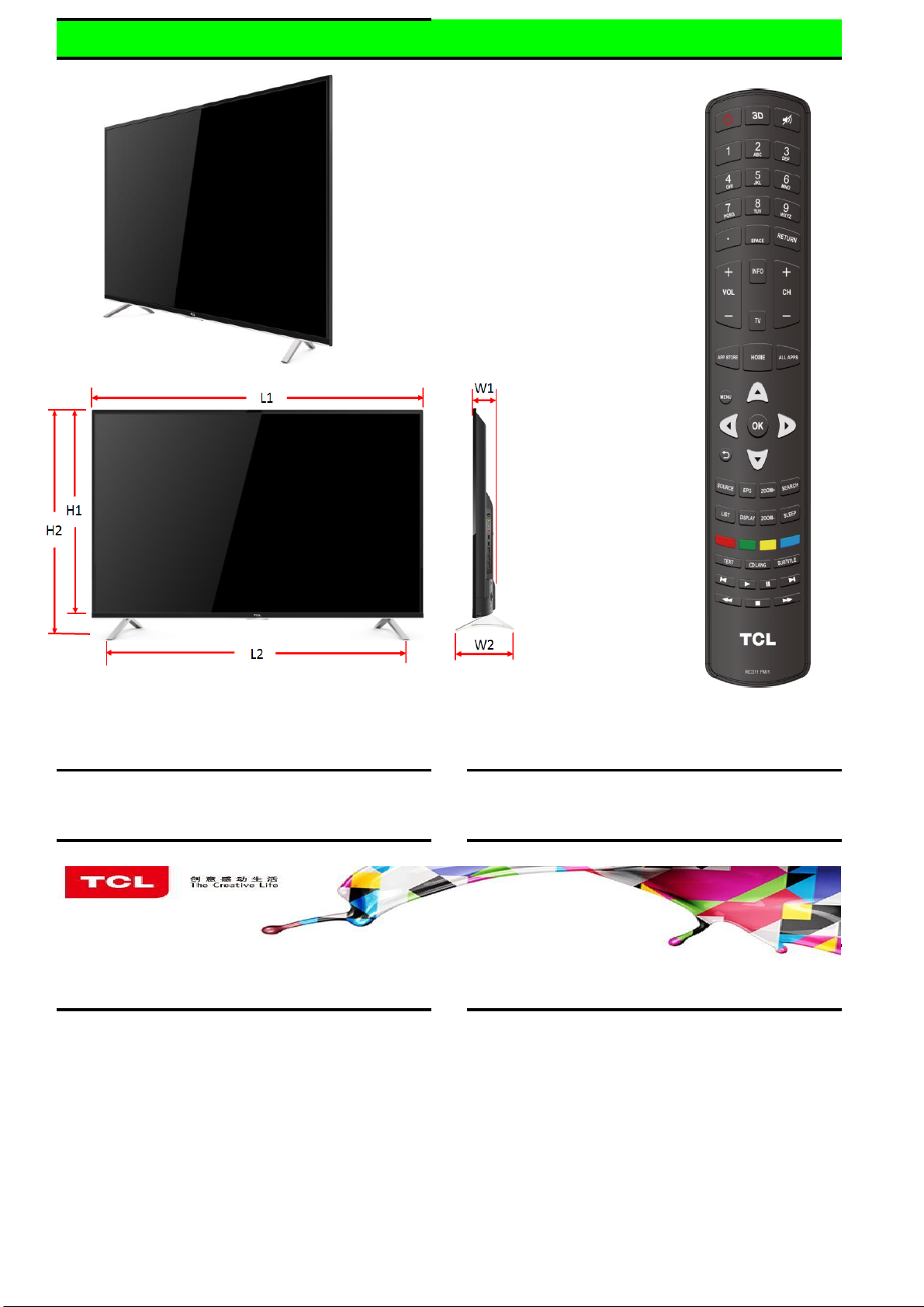
Diagonal size(cm)
102
L1(mm)
917
Slim Edge Design---Up(mm)
13.4
W1(mm)
86
Slim Edge Design---Bottom(mm)
22.5
H1(mm)
537
Slim Edge Design---L&R(mm)
13.4
L2(mm)
731
Carton Dimensions LxWxH(mm)
1105*150*665
W2(mm)
171
Container Loading---20 feet(pcs)
277
H2(mm)
596
Container Loading---40 feet(pcs)
565
Net Weight With Stand(Kg)
8.4
Container Loading--40 feet High (pcs) 658 Net Weight Without Stand (Kg) 8.0
VESA Mounting Dimensions LxH(mm)
100X200
Gross Weight With Packaging(Kg)
11.0
Pre-Installed Application List
nScreen
Connect smart phone to TV and control the
TV with Phone; Push the media files in phone
to TV and enjoy big screen picture quality.
Gesture Control
No
Face Recognize
No
Design and specifications are subject to change without notice!
Sound
Special Function
iCamera
OPTION
Home Cloud
Share video, music, picture files in your home
network
Essential Accessories(Default)
Optional Accessories
No
RF 2.4G and Air mouse No
IR Remote YES
Voice Control No
Remote RC311
Remote Performance and ID Picture
Drafted by:
Approved by:
Remote Performance and ID Picture

Factory Test & Alignment Specification For RT95-AP Series (V1.0)
Content
1. General Description
2. Factory Menu
2.1 Accessing Way
2.2 Factory Menu
2.3 White Balance Menu
3. Design Menu
3.1 Accessing Way
3.2 Design Menu
3.3 Other Menu
3.4 Service Menu
3.5 Param Setting Menu
4. Test & Alignment
4.1 Pre-Conditions and Power Supply Check
...........................................................................................................................................
................................................................................................................................
...........................................................................................................................................
....................................................................................................................................
.......................................................................................................................................
...........................................................................................................................
....................................................................................................................................
........................................................................................................................................
...........................................................................................................................................
.......................................................................................................................................
.........................................................................................................................
...................................................................................................................................
.....................................................................................
3
5
5
6
7
7
8
8
9
9
10
11
11
4.2 Project ID Modification
4.3 Function Test
4.4 LAN/WLAN Test
4.5 SHOP INIT
Appendix
Appendix 1: Warm-up Test
Appendix 2: Software Upgrade
Appendix 3: Network Connection
Appendix 4: White Balance (WB) Adjustment
........................................................................................................................................................
......................................................................................................................................
..........................................................................................................................................
......................................................................................................................
................................................................................................................................
.....................................................................................................................
..............................................................................................................
..........................................................................................................
.....................................................................................
11
12
13
13
14
14
14
15
16
2
Factory Test & Alignment Specification For RT95-AP Series (V1.0)
1. General Description
The information contained in this document is proprietary to TCL SZ FPD lab and shall
not be disclosed by the recipient to third persons without the written permission of the
team leader or GM of R&D.
RT95-AP chassis are designed for Asia & Pacific (AP) market Ready for Smart TV. It
features by its high integration, easy debugging (ADC adjustment free) as well as
convenience in terms of maintenance. Fast software upgrade through USB disk
facilitates both manufacture and after-sale service. Meantime, a variety of functions
involved in Factory Main Menu can not only bring benefits for production, but also
satisfy various demands of customers.
Note: Factory Main Menu (FMM) is divided into Factory menu, Design menu. Factory Menu
covers all indispensable functions during manufacture such as White Balance Adjustment,
USB Upgrading etc., while Design Menu includes Service Menu, Shop Menu, Hotel Menu,
Param Setting, Other Setting etc. Shop Setting(menu) contains many choices for default
settings after manufacture. Some settings like Param Setting and Other Setting is
exclusively used by R&D engineer, anyone else shouldn’t change the settings in the menu.
When you wish to learn the product information like project ID, project name, chassis name,
software version, release date, you can access to Service Menu. In addition, in Hotel Menu,
we also provide a great deal of useful functions for specific applications in hotel.
The main chip is from RealTek and supports below features matrix:
Class
Inputs
&
Outputs
RF Input
(PAL/DVB/DVB-T2)
HDMI
(480i/p, 576i/p, 720p up to 1080i/p, with
HDCP)
VGA 1
VGA audio Shares audio sockets with YPbPr (L+R )
Composite Video Input(HDTV) YPbPr(RCA*3)
Component Audio Input L+R(RCA*2)
AV Input Shares Video(Pr) and audio sockets with YPbPr
Item
CABLE&ANTENNA
RT95
2*HDMI
3
Factory Test & Alignment Specification For RT95-AP Series (V1.0)
Mini interface
USB
(Video, audio and picture)
2 (USB 2.0) + 1 (USB 3.0)
SD
(Secure Digital Memory Card)
1
MHL Shares with one HDMI1
PCMCIA 1
SPDIF output 1*RCA
HEADPHONE 0
NETWORK RJ45 socket
Functions
Internet
The software for U802 can be programed by RTICEv4_Basic.
Every set has its unique HDCP key which is purchased from suppliers or HDCP
Once in a while, the software of main board may be upgraded. Please pay attention to
Inputs
&
Outputs
Audio Out
WIFI
Others Serial connector Multiplexing VGA
U802
U802
IC Details
&
Position
Main program
Mboot
EEPROM U804
(Support online upgrade)
(Support online upgrade)
Note:
certification authority. Please check HDCP function in the process of production.
use the latest software before production.
4
Factory Test & Alignment Specification For RT95-AP Series (V1.0)
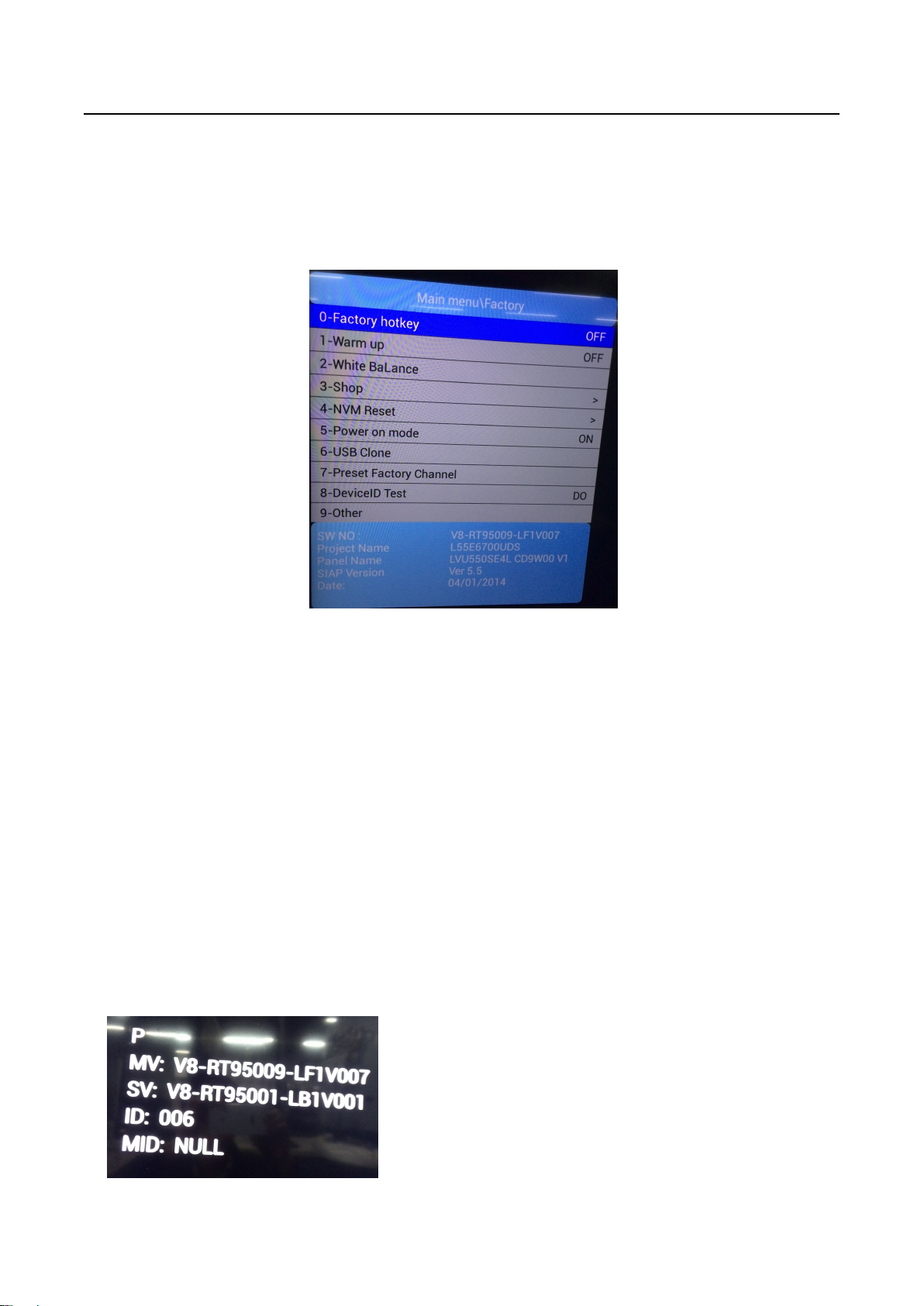
2. Factory Menu
P (Production/Factory mode flag)
MV (Mboot SW Version)
SV (Main SW Version)
ID (Project ID)
MID
Factory Menu is mainly used for factory production and satisfies various demands of customers. It covers
all indispensable functions during manufacture such as White Balance, Warm up, Shop, NVM Reset,
USB Clone etc
.
2.1 Accessing Way
a. When the Factory hotkey item of Factory Menu is disabled (OFF), press Menu button of remote
control, then select TV Settings/Picture/Professional Setting, make sure the cursor stop on
Contrast item submenu. Finally, press 9, 7, 3, 5 consecutively.
b. When the Factory hotkey item of Factory Menu is enabled (ON, you can see the flashing Factory
Captions Info on the lower left corner), press Back button of remote control.
Press RCU “OK” key to enter the submenu.
Press RCU “Right” or “Left” key to change the values.
Press RCU “Right” or “Left” key run the function.
Press RCU “Back” or “Menu” key exit the Factory menu.
Factory Captions Info:
While “FactoryKey” is enabled, there is some toggled display information relative to MV, SV, ID, MID, to
facilitate 100% quick screening without accessing to whatever else menu:
5

Factory Test & Alignment Specification For RT95-AP Series (V1.0)
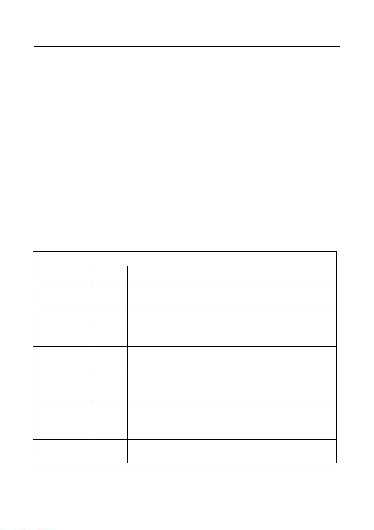
Factory Menu
Name
Default Description
Factory hotkey OFF
Factory Menu shortcut button switch
The item must be disabled (OFF) after production
Warm up OFF
Aging mode, mainly used for factory aging.
Press “Menu” key on keyboard to exit the burning mode.
See Appendix 1 “Warm-up Test”
White Balance ..
White Balance Adjustment ( see details below)
Shop >
It is crucial that the function is executed after production aim to clear information
of production process, ensure user cannot access to Factory Menu after
executing the item.
NVM Reset >
Restore default value except WB, ADC data.
Power On Mode STANDBY
ON: the set will power on after switching on power.
STB: the set will remain standby status after switching on power.
Last: the set will turn to the status in which it lies when last switching off.
If without requirement from certain customer, by default, the Setting should be
STANDBY
USB Clone ..
Select to choose the things you want to clone.
Preset Factory
Channel
..
Preset the channel table of factory. To preset the channel table of certain factory,
first, choose the corresponding factory name. Then press OK button of remote
control and wait OK is displayed on the screen.
DeviceID test DO
Test device ID.
Other
Project Information
SW NO. device info
Version information of Main Software
Project Name device info
Product model
SIACP Version device info
Serial port remote control protocol
Date device info
Release date and time of main software
2.2 Factory Menu
6

Factory Test & Alignment Specification For RT95-AP Series (V1.0)
button on remote control to select certain item and OK to adjust White Balance.
3. Design Menu
Design Menu includes Service Menu, Shop
Menu, Hotel Menu, Param Setting, Other etc.
Shop menu contains many choices for default
settings after manufacture. Some settings like
Param Setting and Other Menu is exclusively
used by R&D engineer, anyone else shouldn’t
change the settings in the menu. When you wish
to learn the product information like project ID,
project name, chassis name, software version,
release date, you can access to Service Menu. In
addition, in Hotel Menu, we also provide a great
deal of useful functions for specific applications in
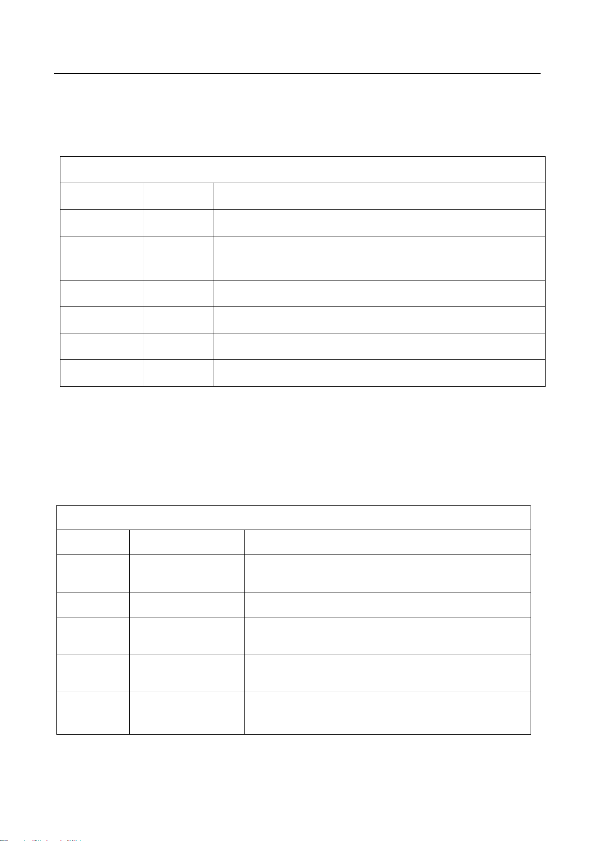
White Balance
Name Default
Description
Source ATV Press RCU left/right key to change the TV source.
Color normal
Select color temperature you intend to adjust Three groups of
color temperature: normal, Cool, Warm are available.
R gain
0-255
Gain of R channel ( cannot be changed after auto calibration)
G gain
0-255
Gain of G channel ( cannot be changed after auto calibration)
B gain
0-255
Gain of B channel ( cannot be changed after auto calibration)
R offset
128
Disabled, keep the default value
G offset
128
Disabled, keep the default value
B offset
128
Disabled, keep the default value
White Balance
init
>
White Balance Initalization. Before WB adjustment, this item should be
executed.
2.3 White Balance Menu
Press the
hotel.
7
Factory Test & Alignment Specification For RT95-AP Series (V1.0)
Design Menu
Name
Default Description
Design Mode
hotkey
OFF
Design Menu shortcut button switch
The item must be disabled (OFF) after production
Factory menu
..
Access to Factory Menu
Other
..
The item includes a number of functions offering convenience for R&D engineer
to solve problems. It is exclusively used by R&D except Hotel Service OnOff
Service menu
..
Provide many useful information for after sale service
Please reference to SERVICE MENU submenu
Param setting
..
Include sound parameter, picture parameter, SSC, DBC, CI Card, Overscan,
WIFI CHECK and USB FILE. Please reference to PARAM SETTING submenu.
SHOP Menu
..
Contain many options which can be chosen according to the requirements of
customers as default settings when leave factory.
See details below.
Hotel menu
..
Include special functions which bring benefits to hotel management. The item is
accessible only when Hotel Service OnOff item is enabled (ON).
3.1 Accessing Way
a. When the Design mode hotkey item is disabled(OFF), press Menu button of remote control, then
select TV Settings/ Picture/ Professional Setting, make sure the cursor stop on Contrast item
submenu, press 1, 9, 5, 0 consecutively.
b. When the Design mode hotkey item of Design Menu is enabled (ON, you can see the flashing
Factory Captions Info on the lower left corner), press Back button of remote control.
Press RCU OK key to enter the submenu.
Press RCU Right/Left key to change the values.
Press RCU Right/Left key run the function.
Press RCU Back/Menu key exit the Factory menu.
Design Captions Information is the same to Factory Captions Info.
3.2 Design Menu
8
Factory Test & Alignment Specification For RT95-AP Series (V1.0)
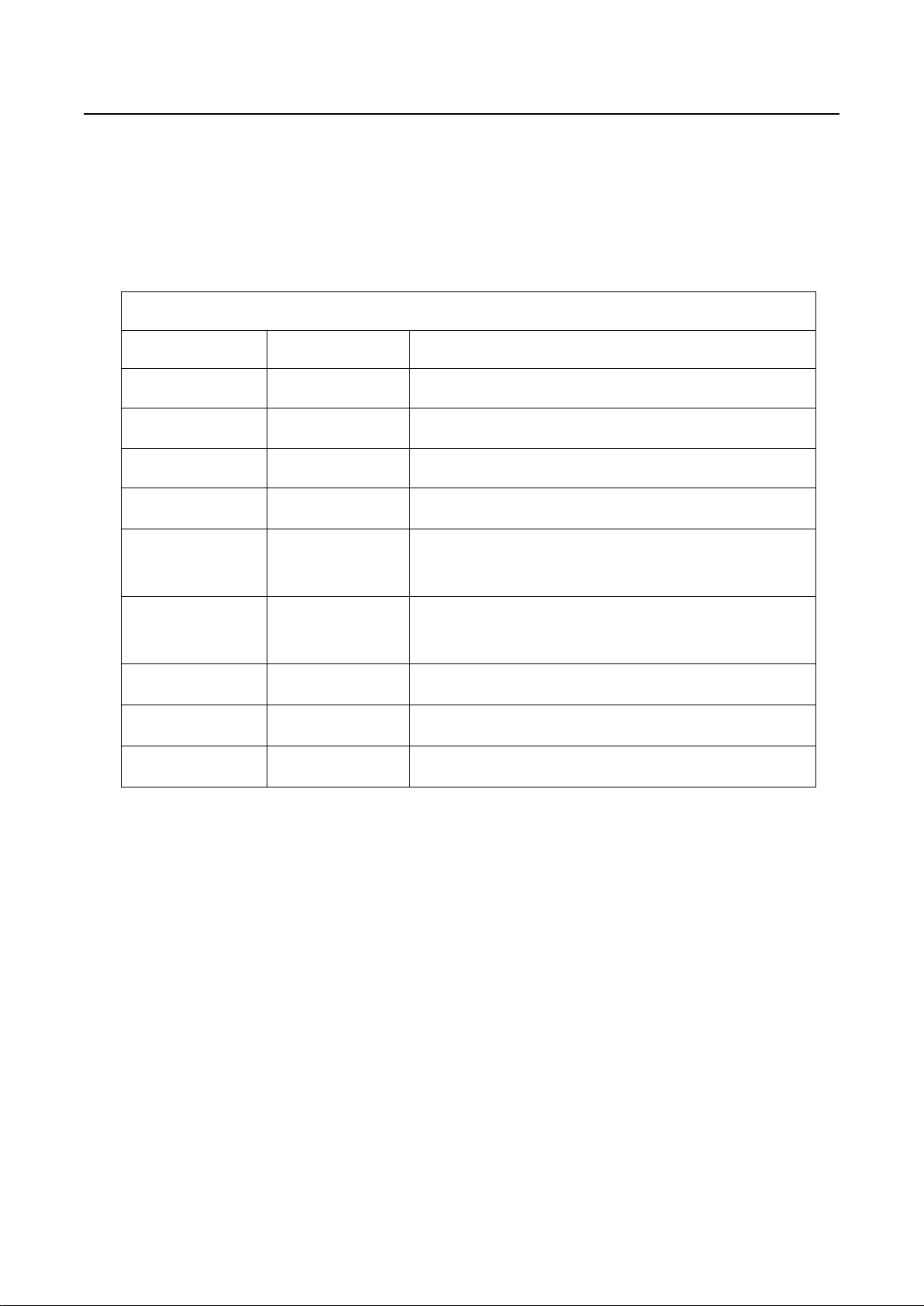
Other Menu
Name Default
Description
TestPattern >
Switch the TV source into test pattern, and restarting TV is the only way to excit.
UartEnable OFF
The switch of VGA serial port information.
The item must be disabled (OFF) after production.
DeviceID ..
Show the device id of TV.
MAC ..
Show the MAC address of TV.
HuanID ..
Show the Huan id of TV.
ClientType ..
Show the Client type information.
Service Menu
Name
Default Description
Project ID
1
Select project parameters, depending on the BOM
description.
Hardware
RTK2995
mainboard Chassis
Software
V8-RT95009-LF1V007
version number of Main Software
Bootloader
V8-RT95001-LB1V001
version number of bootcore
USB Update
..
Update the software by USB disk,
detailed description see Appendix 2 “Software Update”
3.3 Other Menu
The Other Menu contains some TV basic information, with which we can check the TV setting before
production.
3.4 Service Menu
Service Menu contains some basic information of the device, such as Project ID, Hardware, Software
version, USB Update etc. This menu is especially useful for after-sale service.
9
Factory Test & Alignment Specification For RT95-AP Series (V1.0)
Param setting Menu
Name
Default Description
Sound Curve ..
Exclusively used by R&D
Sound Setting ..
Set sound mode, balance, sound scene, etc.
Picture Curve ..
Exclusively used by R&D
Picture Setting ..
Set picture mode, brightness, contrast, backlight, etc.
SSC Adjust ..
Spread Spectrum clocking.
Exclusively used by R&D.
DBC ON
Dynamic Backlight Control.
Exclusively used by R&D.
CI Card ON
Common interface Card switch.
WIFI CHEAK ..
Check the WIFI link
USB FILE ..
Access the USB file
3.5 Param Setting Menu
Param Setting menu contains sound parameter, picture parameter, SSC, DBC, CI Card, Overscan, WIFI
CHECK and USB FILE. But it is exclusively used by R&D engineer, anyone else shouldn’t
change the settings in the menu.
10

Factory Test & Alignment Specification For RT95-AP Series (V1.0)
4. Test & Alignment
All tests and measurements mentioned hereafter have to be carried out at a normal mains voltage
All voltages have to be measured with respect to ground, unless otherwise stated
All final tests have to be done on a complete set including LCD panel in a room with temperature of
The Picture Performance assessment such as White Balance (luminance and colour temperature)
Position Value Test Point
UD60 1.5V 1V5_DDR
U101 2.5V ±1% 2V5
U102 3.3V ±1% 3V3
LD90 12V±10% 12V
LD80 5V±5% 5V
LDA0 1.15V±5% 1V15
UT2 3.3V ±1% TU_3V3
UX2 3.3V ±1% 3V3_DEMO
According to the requirement of order, we suggest take the below steps to finish the appropriate settings.
Note:
(100 ~ 240 VAC)
25+/-7°C
has to be performed into subdued lighted room after at least 60min of warm-up in order to avoid any
temperature drift influence (colorimetry vs time).
4.1 Pre-Conditions and Power Supply Check
Before power-on, please check the board according to the relevant block diagram and circuit diagram,
and make sure that no serious issue or mistake can destroy the board. For example, the output of DC/DC
and LDO should not be shorted to ground.
Supply a suited voltage and power-on, then check the voltage according to the relevant block diagram,
circuit diagram and voltage spec, the error should be less than 5%, for example, the voltage for main chip
(+3V3, +2.5V, VDDC1V15, 1V5_DDR, etc.), the voltage for TUNER (TU_3V3), the voltage for amplifier
(AMP_VCC), etc.
4.2 Project ID Modification
There are different ID stored in the EMMC depending on different Panels settings and Models features,
but there’s only one key branching Project ID able to ensure normal display. And when you power on the
TV set, you should make sure the Project ID is accord with the BOM description. If not, you need to
modify the ID. There is two methods to modify the ID:
11
 Loading...