

TC electronic Konnekt Live Owner's Manual
User’s Manual
English Version
Konnekt Live


1 Read these instructions.
2 Keep these instructions.
3 Heed all warnings.
4 Follow all instructions.
5 Do not use this apparatus near water.
6 Clean only with dry cloth.
7 Do not block any ventilation openings. Install in accordance
with the manufacturer's instructions.
8 Do not install near any heat sources such as radiators, heat
registers, stoves, or other apparatus (including amplifiers)
that produce heat.
9 Do not defeat the safety purpose of the polarized or
grounding-type plug. A polarized plug has two blades with
one wider than the other. A grounding type plug has two
blades and a third grounding prong. The wide blade or the
third prong are provided for your safety. If the provided plug
does not fit into your outlet, consult an electrician for
replacement of the obsolete outlet.
10 Protect the power cord from being walked on or pinched
particularly at plugs, convenience receptacles, and the point
where they exit from the apparatus.
11 Only use attachments/accessories specified by the
manufacturer.
12 Use only with the cart, stand, tripod, bracket, or
table specified by the manufacturer, or sold with the
apparatus. When a cart is used, use caution when
moving the cart/apparatus combination to avoid
injury from tip-over.
13 Unplug this apparatus during lightning storms or when
unused for long periods of time.
14 Refer all servicing to qualified service personnel. Servicing
is required when the apparatus has been damaged in any
way, such as cord or plug is damaged, liquid has been
spilled or objects have fallen into the apparatus, the
apparatus has been exposed to rain or moisture, does not
operate normally, or has been dropped.
• This equipment should be installed near the socket
outlet and disconnection of the device should be easily
accessible.
• To completely disconnect from AC mains, disconnect the
power supply cord from the AC receptacle.
• The mains plug of the power supply shall remain readily
operable.
• Do not install in a confined space.
• Do not open the unit – risk of electric shock inside.
Caution:
You are cautioned that any change or modifications not expressly
approved in this manual could void your authority to operate this
equipment.
Service
• There are no user-serviceable parts inside.
• All service must be performed by qualified personnel.
Warning!
• To reduce the risk of fire or electrical shock, do not expose
this equipment to dripping or splashing and ensure that no
objects filled with liquids, such as vases, are placed on the
equipment.
• This apparatus must be earthed.
• Use a three wire grounding type line cord like the one
supplied with the product.
• Be advised that different operating voltages require the use
of different types of line cord and attachment plugs.
• Check the voltage in your area and use the correct type.
See table below:
Voltage Line plug according to standard
110-125V UL817 and CSA C22.2 no 42.
220-230V CEE 7 page VII, SR section
107-2-D1/IEC 83 page C4.
240V BS 1363 of 1984.
Specification for 13A fused
plugs and switched and
unswitched socket outlets.
The lightning flash with an arrowhead symbol within
an equilateral triangle is intended to alert the user to
the presence of uninsulated “dangerous voltage”
within the product's enclosure that may be of sufficient
magnitude to constitute a risk of electric shock to persons.
The exclamation point within an equilateral triangle is
intended to alert the user to the presence of important
operating and maintenance (servicing) instructions in
the literature accompanying the product.
IMPORTANT SAFETY INSTRUCTIONS
a

EMC/EMI
This equipment has been tested and found to comply
with the limits for a Class B Digital device, pursuant to
part 15 of the FCC rules.
These limits are designed to provide reasonable
protection against harmful interference in residential
installations. This equipment generates, uses and can
radiate radio frequency energy and, if not installed and
used in accordance with the instructions, may cause
harmful interference to radio communications. However,
there is no guarantee that interference will not occur in a
particular installation. If this equipment does cause
harmful interference to radio or television reception,
which can be determined by turning the equipment off
and on. The user is encouraged to try to correct the
interference by one or more of the following measures:
• Reorient or relocate the receiving antenna.
• Increase the separation between the equipment and
receiver.
• Connect the equipment into an outlet on a circuit
different from that to which the receiver is
connected.
• Consult the dealer or an experienced radio/TV
technician for help.
For Customers in Canada:
This Class B digital apparatus complies with Canadian
ICES-003.
Cet appareil numérique de la classe B est conforme à la
norme NMB-003 du Canada.
Certificate of Conformity
TC Electronic A/S, Sindalsvej 34, 8240
Risskov, Denmark, hereby declares on own
responsibility that the following product:
Konnekt Live
that is covered by this certificate and
marked with CE-label conforms with
following standards:
EN 60065 Safety requirements for mains
(IEC 60065) operated electronic and
related apparatus for household
and similar general use
EN 55103-1 Product family standard for
audio,video, audio-visual and
entertainment lighting control
apparatus for professional use.
Part 1: Emission.
EN 55103-2 Product family standard for
audio, video, audio-visual and
entertainment lighting control
apparatus for professional use.
Part 2: Immunity.
With reference to regulations in following
directives:
73/23/EEC, 89/336/EEC
Issued in Risskov, April 2007
Mads Peter Lübeck
Chief Executive Officer
EMC / EMI & CERTIFICATE OF CONFORMITY
b

TC Electronic, Sindalsvej 34, DK-8240 Risskov – info@tcelectronic.com Manual revision 1.2English Version
INTRODUCTION
Safety Instructions . . . . . . . . . . . . . . . . . . . . . .a
EMC/EMI & Certificate of Conformity . . . . . . . .b
Table of contents . . . . . . . . . . . . . . . . . . . . . . .3
Introduction . . . . . . . . . . . . . . . . . . . . . . . . . . . .4
Konnekt LIVE features . . . . . . . . . . . . . . . . . . .5
Quick Setup guide . . . . . . . . . . . . . . . . . . . . . .6
Konnekt Live & and Ableton Live . . . . . . . . . . .7
OVERVIEW
Front panel overview . . . . . . . . . . . . . . . . . . . .8
Rear panel overview . . . . . . . . . . . . . . . . . . . .11
SETUP EXAMPLES
Setup examples - LIVE . . . . . . . . . . . . . . . . .12
Setup examples - Turntable . . . . . . . . . . . . . .13
CONTROL PANEL
Mixer Page . . . . . . . . . . . . . . . . . . . . . . . . . . .14
Preset management . . . . . . . . . . . . . . . . . . . .17
Setup Page . . . . . . . . . . . . . . . . . . . . . . . . . . .18
Routing modes . . . . . . . . . . . . . . . . . . . . . . .24
Konnekt WDM driver . . . . . . . . . . . . . . . . . . .25
System Settings . . . . . . . . . . . . . . . . . . . . . . .26
Firmware update . . . . . . . . . . . . . . . . . . . . . . .29
Reset to Default . . . . . . . . . . . . . . . . . . . . . . .29
Fabrik C Live . . . . . . . . . . . . . . . . . . . . . . . . .30
Fabrik R Live . . . . . . . . . . . . . . . . . . . . . . . . .42
Resonance Filter . . . . . . . . . . . . . . . . . . . . . .48
The Konnekt Tuner . . . . . . . . . . . . . . . . . . . . .52
APPENDIX
Bus Power Notes . . . . . . . . . . . . . . . . . . . . . .54
ASIO channel names . . . . . . . . . . . . . . . . . . .55
Signal Flow . . . . . . . . . . . . . . . . . . . . . . . . . .56
FAQ . . . . . . . . . . . . . . . . . . . . . . . . . . . . . . . .57
Shortcut keys . . . . . . . . . . . . . . . . . . . . . . . . .57
DICE background . . . . . . . . . . . . . . . . . . . . . .57
Technical Specifications . . . . . . . . . . . . . . . . .58
TABLE OF CONTENTS
3

4
INTRODUCTION
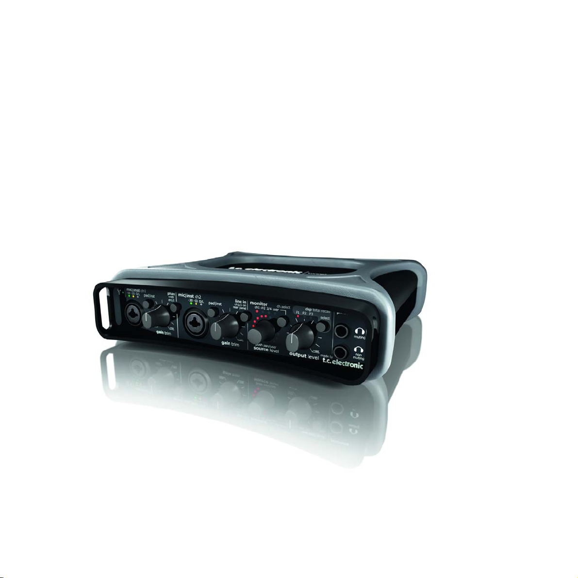
Congratulations on your purchase of the Konnekt LIVE
To call Konnekt Live an intriguing interface for live performers is merely scratching the surface. Whereas most audio
interfaces on the live laptop performance scene are designed for recording purposes TC Electronic’s interface raises the bar
and offers clear-cut playback advantages to live laptop performers.
Imagine a master compressor, a Finalizer that puts you in full control of your output. Add to that Konnekt Live’s extensive
output routing that enhances the audio passing through via its optimized analog output section. Bundled with Ableton Live
software and a suite of built-in DSP effects, you won’t find a more versatile interface for your live performance.
Typically, real-time, high quality output processing puts heavy demands on your CPU. Not so with Konnekt Live. Since all
DSP processing takes place inside Konnekt Live, all you have to worry about is being creative - your computer is left with
plenty of headroom for other tasks.
Konnekt Live - studio-quality output, road-sturdy control and unsurpassed DSP effects for the digital artist
Studio-quality sound
At its most basic, the sound quality of Konnekt Live takes your performance to the next level. Whether you run pre-recorded
tracks, effects, plug-ins or live inputs through it, Konnekt Live easily outperforms other audio interfaces, compact mixers or
budget rack units on the scene. You can think of this interface as a high quality yet compact mixer that integrates perfectly
with balanced or unbalanced systems, big PA rigs and active speaker systems alike.
DSP effects inside
Konnekt Live houses a suite of advanced effects, including DSP, under its hood that were designed with your toughest
performance requirements in mind. The effects quality so far only known from recording studios is now within reach for
your live setup.
Fabrik C Live
Compression with extensive output options – the perfect Finalizer for any venue. Its unique MINT (Meta Intuitive Navigation
Technology) user interface allows you to respond intuitively to what you hear, taking the bore right out of tweaking tons of
parameters and settings
Fabrik R Live
Add up to 9 classic reverb algorithms for breathtaking effects and vocal reverb on loops, pre-recorded tracks, live vocals,
instruments or keyboards
ResFilter
Lo-cut/hi-cut filter that offers you ultra fat filtering effects. Throw in resonance, 6, 12 and 24 slopes for even more
stunning sounds. Its inter-communication-bus facilitates controlling and tweaking multiple plug-ins and parameters from
one plug-in, cross-fading between two plug-ins etc.

5
KONNEKT LIVE FEATURES
• Outstanding IMPACT™ mic pre-amps
• True Hi-Z inputs
• Front panel control of internal mixer parameters
• Analog volume control for perfect integration with
powered speakers
• Network up to 4 units via the TC NEAR™ 1394
FireWire based network to get more inputs, outputs
and effects channels
• Full feature direct monitoring – With effects and also
between networked units
• Intuitive control panel with automatic input detection
• 3 DSP programs for total recall of internal routing,
mixer and effects settings
• XLR to RCA jacks with RIAA filter for direct
connection of turntable
• FireWire bus powered
• DICEII digital interface chip with JETtm Jitter
Elimination Technology
• Low latency drivers: WDM, ASIO and CoreAudio
(including Intel Macs)
• Dual headphone outputs, one with auto speaker
muting
• 24-bit/192kHz sampling rate
• Sample accurate MIDI
• 14/14 I/O: 2 mic/inst/line, 2 line inputs and 4 line
outputs, 8 ADAT and 2 S/PDIF (optical and
coaxial) inputs and outputs
• Built-in real-time DSP effects; Fabrik R Live reverb
and Fabrik C Live channel strip based on MINT™
• VST integration of Fabrik R Live and Fabrik C Live
• Native ResFilter included
• Assimilator Konnekt included
• Ableton Live 6 TC Electronic edition included
• Built-in Tuner displayed both via TC Near Control
panel and front panel lightring.
Sturdy design
Its sturdy, road-ready casing is designed for the rigors of live performing and the life on the road. It fits right under your
laptop and its heavy rubber frame serves as a solid grip on tilted or slippery surfaces allowing this baby to take a serious
amount of gravitational punishment before it gives in to the laws of physics.
Versatility
If you crave that old school touch, stay tuned: Konnekt Live comes with a turntable cable and an on-board RIAA plug-in.
The selection of RIAA filters gives you studio-quality vinyl ripping to mix in with your own music or mash-ups. Konnekt
Live’s MIDI I/O allows you to plug an external MIDI controller right into the loop without a USB MIDI interface. Assign the
front panel light ring as a MIDI controller for tweaking optional parameters if you like to loop in a more tangible grip of
things.

6
Up and running in 10 minutes
This quick-guide will help you set up the Konnekt
Live in a typical application. For further details
please refer to later sections of this manual.
Unpacking
• Open the box from the top and remove cabling.
• Lift out styrofoam insert, then using both hands lift
out Konnekt.
• Remove plastic bag from Konnekt.
• Inspect your Konnekt for signs of transit damage.
• In the unlikely event of this having occurred, inform
the carrier and the supplier.
• Keep all the packaging if damage has occurred, as
this will show evidence of excessive handling force.
• It is also a good idea to keep the packaging if possible
for future transportation.
Check contents
The package should contain the following items:
• Konnekt audio interface
• Power supply
• FireWire cable
• XLR to RCA jacks for connecting a turntable
• CD with software etc.
• Safety Instructions
Computer Requirements
Mac OS
• PowerPC (1 GHz or faster) or Intel CPU
• 256 MB RAM
• FireWire (IEEE 1394) port*
• OS X 10.3.9
Windows
• Pentium 4, 1.6 GHz or faster
• 256 MB RAM
• FireWire (IEEE 1394) port*
• Windows XP
* We recommend running Konnekts on a dedicated FireWire bus.
If your computer has one or more FireWire connections on the
chassis they will typically run on the same FireWire bus. You may
connect the Konnekt to one of these. If you intend to run more
FireWire devices simultaneously, such as e.g. an external hard drive,
we recommend running this device on a separate bus.
This would typically be on an installed FireWire PCI card. Note that
such a FireWire PCI card typically has 3 ports but these also operate
on a single bus.
Software installation
• We recommend installing the software before
connecting the Konnekt.
• Refer to the Konnekt Installation Guide supplied in
the package and on the Konnekt CD.
• If you are familiar with software installation
procedures in general you may simply insert the
accompanying CD-ROM in your computer’s CD drive
and follow the instructions.
TC Near control panel
If Konnekt drivers are installed correctly you are able to
open the TCNear control panel.
On W
indows computers:
Press: Start/Programs/TC Electronic/TC Near
The TC Near can also be accessed via the Windows
Control panel.
On Mac computers:
/Applications/TC Near
You may also start the application from System
Preferences.
QUICK SETUP GUIDE

KKoonnnneekktt LLiivvee ccoommeess wwiitthh aa ssppeecciiaall eeddiittiioonn ooff AAbblleettoonn LLiivvee
ffoorr TTCC EElleeccttrroonniicc..
The following is a quick reference
guide to setting up Konnekt Live with Ableton Live.
For instructions on using Ableton Live please refer
to the reference manual for Ableton Live integrated
within the program.
• Install Ableton Live from the CD.
• Open Ableton Live.
• Go to: Options/Preferences/Audio.
In this menu - select ASIO as driver type and TC Near
as Audio Device.
• Go to: Options/Preferences/File Folder
• Set the “Use VST Plug-Ins Custom folder to “on”.
Note that if you have created and installed your VST
plug-ins in a different folder than the default, you
must browse and select that folder first.
• Konnekt Live is now setup as the default audio device
for Ableton Live and Ableton Live is setup to use
Fabrik C Live, Fabrik R Live, ResFilter and Assimilator
Konnekt.
77
KONNEKT LIVE & ABLETON LIVE
phan line in
muting
non
muting
ch.select
push pan/userpush pan/userpush pan/user
+48V ch1/2 on
ch1/2
rear panel
ch1 ch2 3/4 user
mic|inst ch1 mic|inst ch2
monitor
phones
gain trim
gain trim
source level output level
made by
dsp total recall
P1 P2 P3
select
max max maxmin min min
-30-30 -10-10 O/LO/L
pad|inst pad|inst
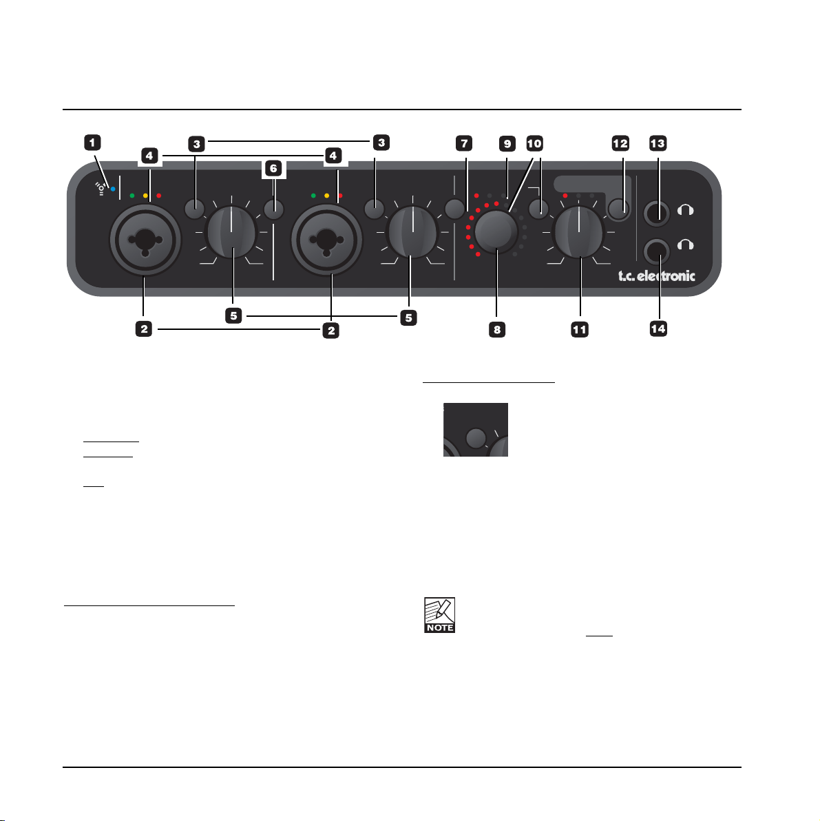
1 FireWire/Power LED indicator
When Konnekt is hooked up via FireWire, the blue
LED can indicate the following:
Steady lit:
Sufficient power
Flashing: Uploading firmware, hardware error or
FireWire communication error.
Off: The Konnekt has no connection to the
driver, maybe because the driver is not
installed.
2 Mic/Inst ch1/ch2 on Combo XLR/Jack
Combo XLR/Jack inputs. Both XLR and 1/4 inch jack
can be used with this connector.
The XLR connection (balanced)
Connect a microphone and your signal is processed via
the IMPACT™ mic pre-amps.
- For condenser microphones activate phantom power.
see also (6) on the following page.
- The Input LEDs (4) indicate the level of the input
signal. If the red O/L LED (overload) is lit, your signal
is too “hot” and you should press “PAD/INT” to
attenuate the signal by 20 dB.
The 1/4 jack connection
- Press PAD/INST to activate this circuit.
The 1/4 “jack part” of the connector is a high quality HiZ circuit that is designed especially for connecting a
passive guitar pick-up system (e.g. Strat-type) directly.
The jack inputs on the front panel are unbalanced. If you
wish to connect balanced equipment using TRS jacks you
should connect via the line inputs on the rear panel.
Important!
If you use the 1/4 jack part of the Combo jack/xlr
connection PAD/INST must
be set to “in”
position.
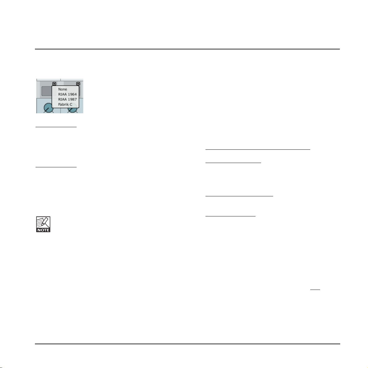
Connecting a turntable
A turntable can be connected to the Mic/Inst inputs by
using the supplied RCA to XLR cable. With a turntable
connected a RIAA filter must be inserted.
L
pad|inst
FRONT PANEL OVERVIEW
8
FRONT PANEL OVERVIEW
9
Both RIAA 1964 and RIAA 1987 formats are supported.
Select between the two RIAA formats via the mixer page.
RIAA filter 1964
The RIAA filter 1964 gently enhances the low-end
frequencies with 6 dB per descending octave. The high
end frequencies are attenuated also with 6 dB per octave.
Around 1 kHz the level is left untouched.
RIAA filter 1987
The RIAA 1987 is a variation of the original 1964 filter.
In this type a soft cut in the low-end frequencies has
been added to reduce rumble and acoustic feedback.
Depending on you specific application you may prefer one
or the other.
RIAA filters are not available at 192 kHz.
3 Pad/Inst selectors
The PAD/INSTRUMENT selector can attenuate the
input sensitivity by 20 dB. If you cannot attenuate the
signal sufficiently using the GAIN/TRIM knob you
should use the -20 dB position. This is typical when
connecting line-level instruments.
Use PAD (out-position) when a turntable is connected via
RIAA converter cables.
4 Input LEDs
Three input level indicators. -30 dB, -10 dB and 0 dB.
First adjust the Gain Trim so the 0 dB LED is only lit
at absolute peaks. Then reduce the Gain Trim slightly
so the 0 dB LED is never lit.
5 Gain/Trim
Use this control to set the appropriate input level.
(see previous paragraph).
6 Phantom Power +48V
The XLR part of the Combo XLR/Jack connections
features +48V phantom power when this switch is
pressed. Phantom power is used to power line-drivers
and condenser microphones.
Ther
e are three main types of microphones
Condenser microphone
- phantom power required
except for some models that use proprietary power
supplies or built-in batteries. Please check the
microphone's manufacturer specifications for details.
Electrodynamic microphone
- phantom power is not
required but does no harm to the microphone.
Ribbon microphones- phantom power could damage
the microphone. Search advice and documentation
from the manufacturer of the microphone!
Only the condenser type requires phantom power.
It is however no problem combining a condenser
microphone in e.g. ch. 1, with a standard
electrodynamic microphones (such as e.g. a Shure
SM57) in ch. 2. Nor is it any problem to activate
phantom power and use a condenser microphone to
one of the inputs and connect a guitar using a 1/4
jack to the other input, as phantom power only
concerns the XLR connections.
7 Line In - ch 1/2 on rear panel
This switch alternates between using the front panel
inputs or rear panel inputs for channels 1/2.
Rear panel inputs are line inputs.
Connect a TV, a radio tuner or any secondary
device that you don’t use in music production to
Line inputs 1/2 on the rear panel. Use the “Line
In” switch to alternate between front and rear
panel inputs.
8 Source Level (push to control Pan)
Controls the level or pan-position of the selected
channel. The lightring shows the level or pan position
of the selected channel.
By default the Source Level knob controls the source
level of the selected channel. Press once and turn the
knob to pan the signal. Leave the knob untouched for
1 second and it will automatically return to volume
control function.
9 Monitor LEDs
Indicate which channel is monitored. Select channels
using the Ch. Select button.
10 Ch. Select
The LED lightring around the SOURCE level knob
indicates the source level of channel you have
selected or the pan position if the Source Level knob
(8) has been pushed.
Select between monitoring the following channels:
Ch 1 - Front or rear panel input channel 1*
Ch 2 - Front or rear panel input channel 2*
Select between channel 1/2 front and
rear panel using the Line in switch on the
front panel.
Ch 3/4 - Channels 3/4 on rear panel
User - The Setup page allows you to setup which
channel/channels are monitored when
“User” is selected. The options will vary
depending on the connected devices.
line in
ch1/2 on
rear panel
m
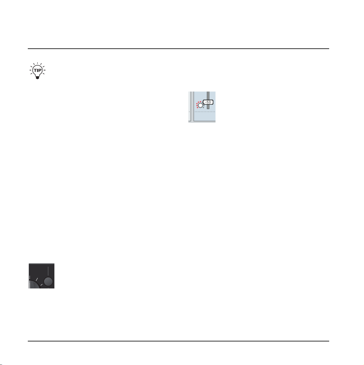
It is also possible to assign a level control of a channel to
the LED lightring via the Mixer page on the TC Near
computer user-interface by pressing the lightring icon on
the channel of your choice:
11 Output level
Sets the output level of analog outputs 1-2 and of the
headphone outputs.
12 DSP Total Recall
Three program settings can be stored in locations P1,
P2 and P3. These programs are total recall presets
recalling settings from both mixer page, setup page
and plug-in pages. Total recall of Fabrik plug-in
settings does not apply when routing is set to plug-in
mode.
13 Phones muting
Connect a set of headphones here. Main outputs will
be muted.
14 Phones non-muting
Connect a set of headphones here. Signal is still
passed to Main outputs.
FRONT PANEL OVERVIEW
10
11
line outputss/pdifMIDI
adat|optical
line inputs
DI
DO
ch1|main Lch3(L) ch3(L) ch1(L)
ch2|main Rch4(R) ch4(R) ch2(R)
in
bus powered
firewire
DI
DO
out
power
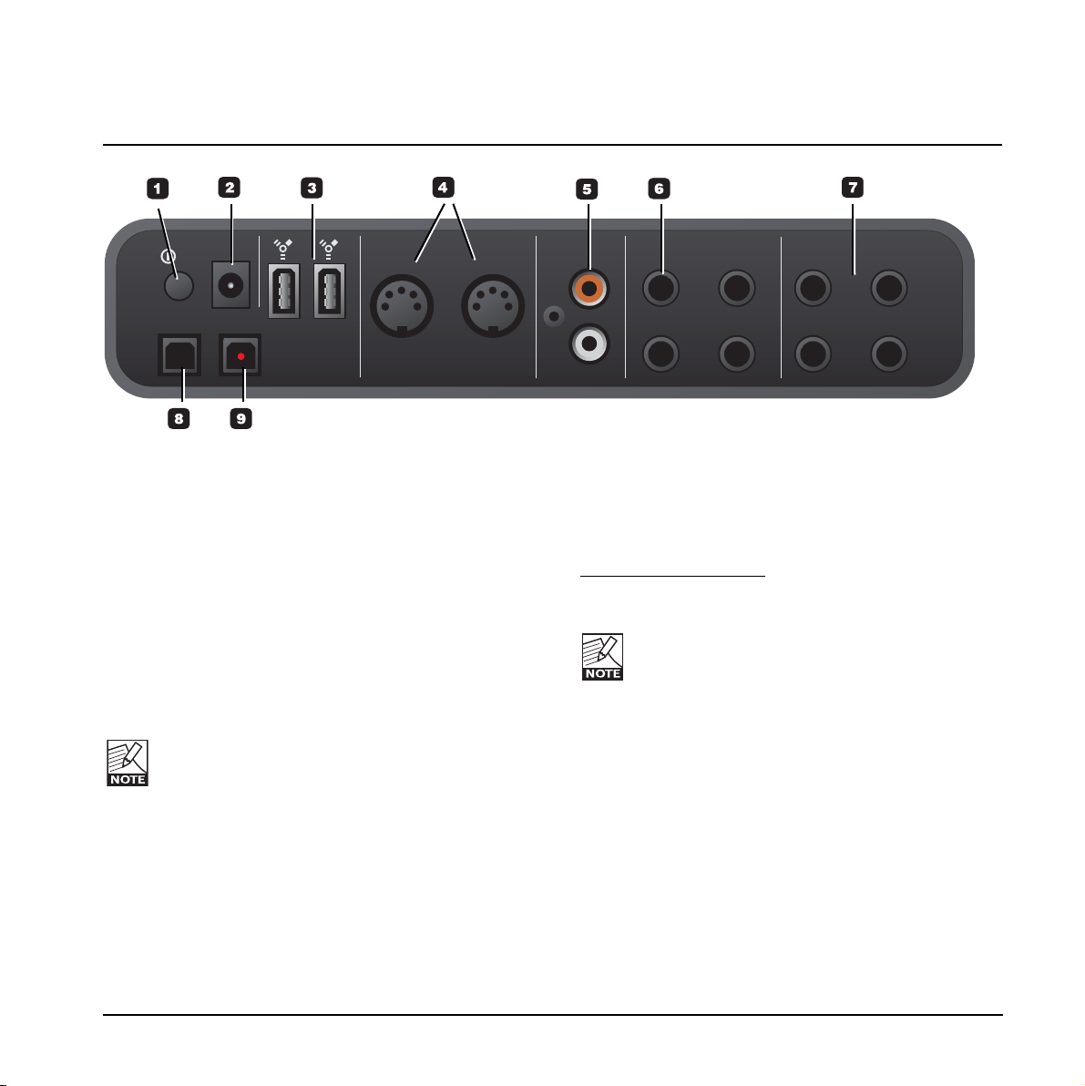
REAR PANEL OVERVIEW
1 Power Switch
On/off switch for the unit.
2 Power In
Konnekt can be bus-powered from the computer’s
FireWire port. Check your computer’s specifications. If
more than one Konnekt is used or your computer
delivers insufficient power on the FireWire port - use
the supplied 12VDC power supply.
3 FireWire connectors
IEEE 1394 connectors for connecting to a computer
and/or linking multiple Konnekt units. Konnekt can be
bus-powered* from the computer’s FireWire port.
Check your computer’s specifications.
Before plugging the firewire connectors, make
sure that plugs are positioned correctly.
* Please read the section regarding bus-power on page
55.
4 MIDI In/Out
Standard MIDI in/out. MIDI out is automatically set to
MIDI thru in stand alone mode.
When Konnekt is used in stand-alone mode, MIDI out
always acts as MIDI thru.
5 Digital in/out - Coaxial S/PDIF
24 bit digital in/out on S/PDIF. In addition to standard
I/O it is possible to insert e.g. an external digital
effects unit and use this as a send effect.
6 Line Outputs (balanced)
1/4 inch jack outputs for:
- Main Left (ch 1) and Main Right (ch 2).
- Left (ch 3) and Right (ch 4)
When connecting Main outs to a device (e.g.
active speakers) with balanced inputs: “ground”
and “cold” must be connected.
- On XLR type plugs this is pins 1 and 3.
- On Jack type plugs it is “sleeve” and “ring”.
7 Line Inputs (balanced)
- Ch 1 (L)
- Ch 2 (R)
- Ch 3 (L)
- Ch 4 (R)
8 DI - Digital In
Optical S/PDIF or ADAT Toslink for up to 8 channels of
digital in, depending on format and sample rate.
9 DO - Digital Out
Optical S/PDIF or ADAT for up to 8 channels of digital
out.
12
SETUP EXAMPLES - “LIVE”
line outputss/pdifMIDI
adat|optical
line inputs
DI
DO
ch1|main Lch3(L) ch3(L) ch1(L)
ch2|main Rch4(R) ch4(R) ch2(R)
in
buspowered
firewire
DI
DO
out
power
phan linein
muting
non
muting
ch.select
pushpan/userpushpan/userpushpan/user
+48V ch1/2on
ch1/2
rearpanel
ch1ch2 3/4 user
mic|inst ch1 mic|inst ch2
monitor
phones
gaintrim
gaintrim
sourcelevel output level
madeby
dsptotal recall
P1 P2 P3
select
max max maxmin min min
-30-30 -10-10 O/LO/L
pad|inst pad|inst
KEYBOARD for MIDI recalls
and additional live keys
MIDI OUT
Amp
PA SYSTEM
Headphones
level
Output 3/4
FRONT
REAR
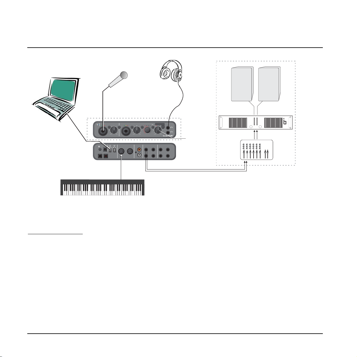
This example illustrates how Konnekt integrates perfectly
in a live setup. The objects in a live setup could be:
Elements in this setup:
• DAW/laptop as source for playing audio-files.
• Headphones for undisturbed monitoring using the
OUTPUT level control as separate headphones level.
• Microphone for vocals utilizing Konnekt IMPACT™
pre-amps and e.g. the Fabrik C channel strip.
• MIDI keys for additional keyboards and/or program
changes.
• Distribution to PA (amp-speakers) using the SOURCE
level control as separate level control.
Connect all devices according to the illustration above.
Remember to activate phantom power if you are using a
condenser microphone. Also note that outputs 3/4 in this
setup are used as main outs to PA.
Advantage of this setup
This setup enables you to route different signals to the
headphones and PA system via the DAW. This is useful
for numerous purposes. E.g. for excellent cue monitoring
for DJs as well as individual level control of the two
signals.
SETUP EXAMPLES - TURNTABLE
13
line outputss/pdifMIDI
adat|optical
line inputs
DI
DO
ch1|main Lch3(L) ch3(L) ch1(L)
ch2|main Rch4(R) ch4(R) ch2(R)
in
buspowered
firewire
DI
DO
out
power
phan line in
muting
non
muting
ch.select
pushpan/userpushpan/userpushpan/user
+48V ch1/2 on
ch1/2
rearpanel
ch1ch2 3/4 user
mic|inst ch1 mic|inst ch2
monitor
phones
gaintrim
gaintrim
sourcelevel output level
madeby
dsptotal recall
P1 P2 P3
select
max max maxmin min min
-30-30 -10-10 O/LO/L
pad|inst pad|inst
Amp
PA SYSTEM
Headphones
level
Output 3/4
Out level to PA
Ch select set to “3/4”
FRONT
REAR
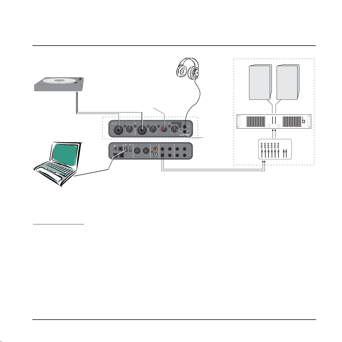
This example illustrates how a turntable can be connected to
Konnekt Live using the supplied XLR to RCA cable.
Elements in this setup
:
• Turntable for vinyl.
• DAW/laptop as recording device.
• Headphones for monitoring.
• Distribution to amp and speakers using the SOURCE
level control as separate level control.
Connections
Connect all devices according to the illustration above.
• The turntable is connected to the XLR inputs on the
frontpanel using the RCA to XLR cables.
• PAD/Inst selectors must be set in “out” (PAD)
position.
• Select RIAA 1964 or RIAA 1987 via the TC Near
Control panel.
• Outputs 3/4 are used as main outs to amp and
speakers.
CONTROL PANEL - MIXER PAGE
14
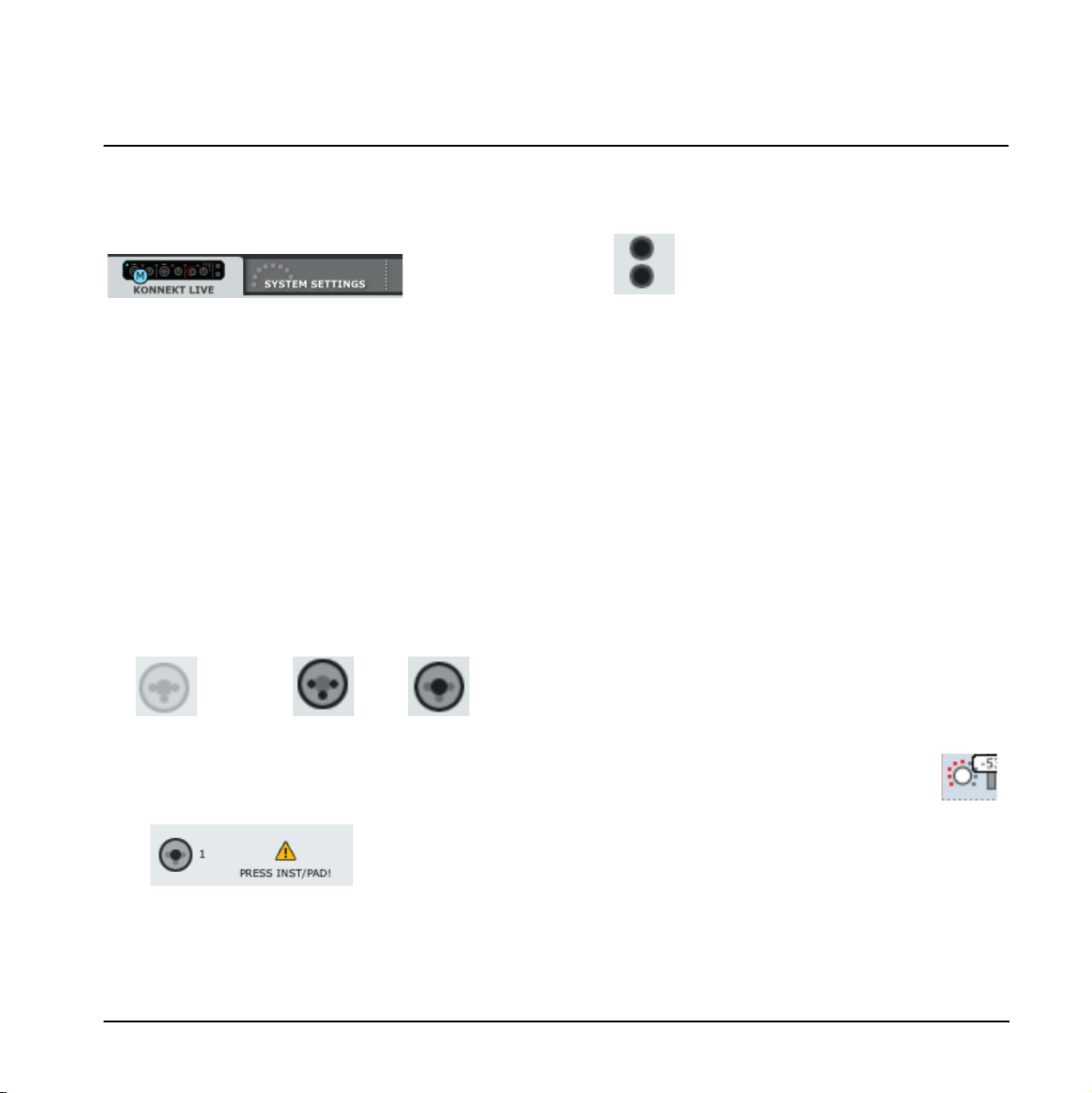
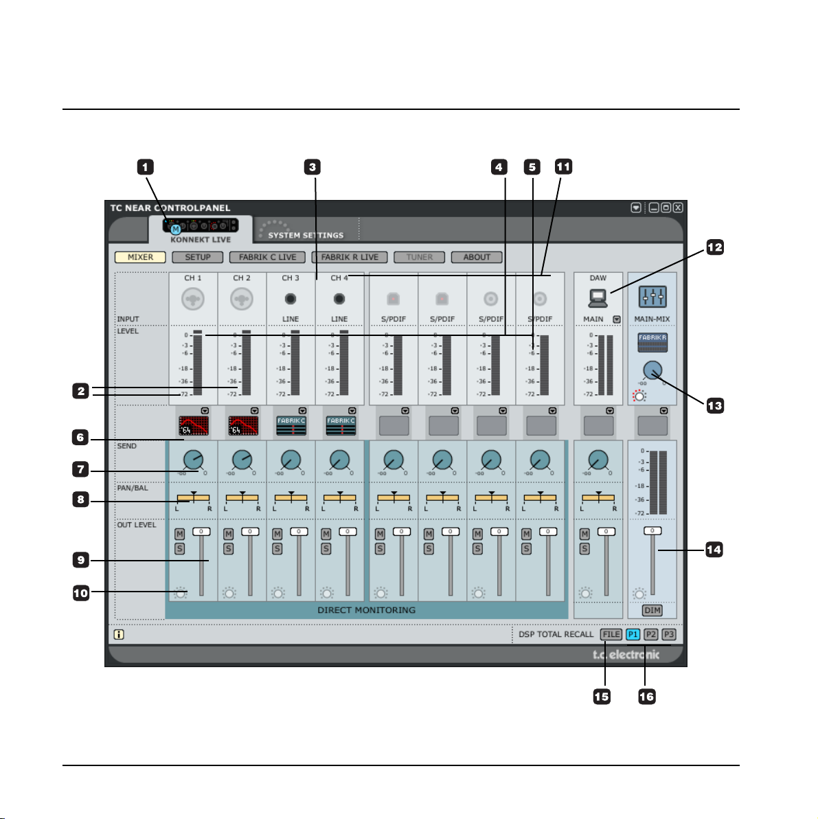
1 The Konnekt select tabs
Use the select tabs to switch between the Konnekts in
your setup and the System Settings page.
Channels1/2 & 3/4
2 Channels 1/2 - mono/stereo
The illustration on the previous page shows channels
1/2 in dual mono mode. The channels may be linked
to one stereo channel via the Setup page. This will
change the appearance of these channels. Please
refer to the description of the Setup page on the
following pages for details.
3 Ch1/Ch2 auto-sensing input
Channel 1/2 connections on the front panel are autosensing. They automatically detect whether you have
connected an XLR (microphone) or 1/4” jack
(instrument), and indicate this graphically.
These are the options
Nothing connected Mic/XLR Inst./jack
When an instrument jack is plugged you must press
Inst/Pad to activate the input. This is also indicated on
the setup page:
All Channels
4 Input Meters
These meters indicate the level of the signal present
on the input channels. Best signal to noise ratio is
achieved when the input signal only occasionally
peaks at “0”. Adjust the level on the sending device.
5 Clip LED (RED)
When the Clip LED is lit the signal is too hot. Reduce
the level on the sending device to compensate.
6 Fabrik C Live and RIAA symbols
Fabric C Live and RIAA filters can be selected via the
drop-down menu.
7 Send
Use the SEND knobs to send signal from each
channel to the Fabrik R Live (reverb).
To actually hear the reverb make sure that Fabrik R
Live is active.
8 Pan
Pan left/right using the left mouse button.
Press Ctrl+Shift and left mouse button to center.
9 Out Level
Master out level.
10 lightring Assignment
All faders with the “lightring” indication can be
assigned to the “source” controller on the front panel.
When assigned, the lightring on the front panel
displays the fader position.
CONTROL PANEL - MIXER PAGE
15
Ch3/Ch4
Connections for line channels 3/4 are located on the
rear panel.
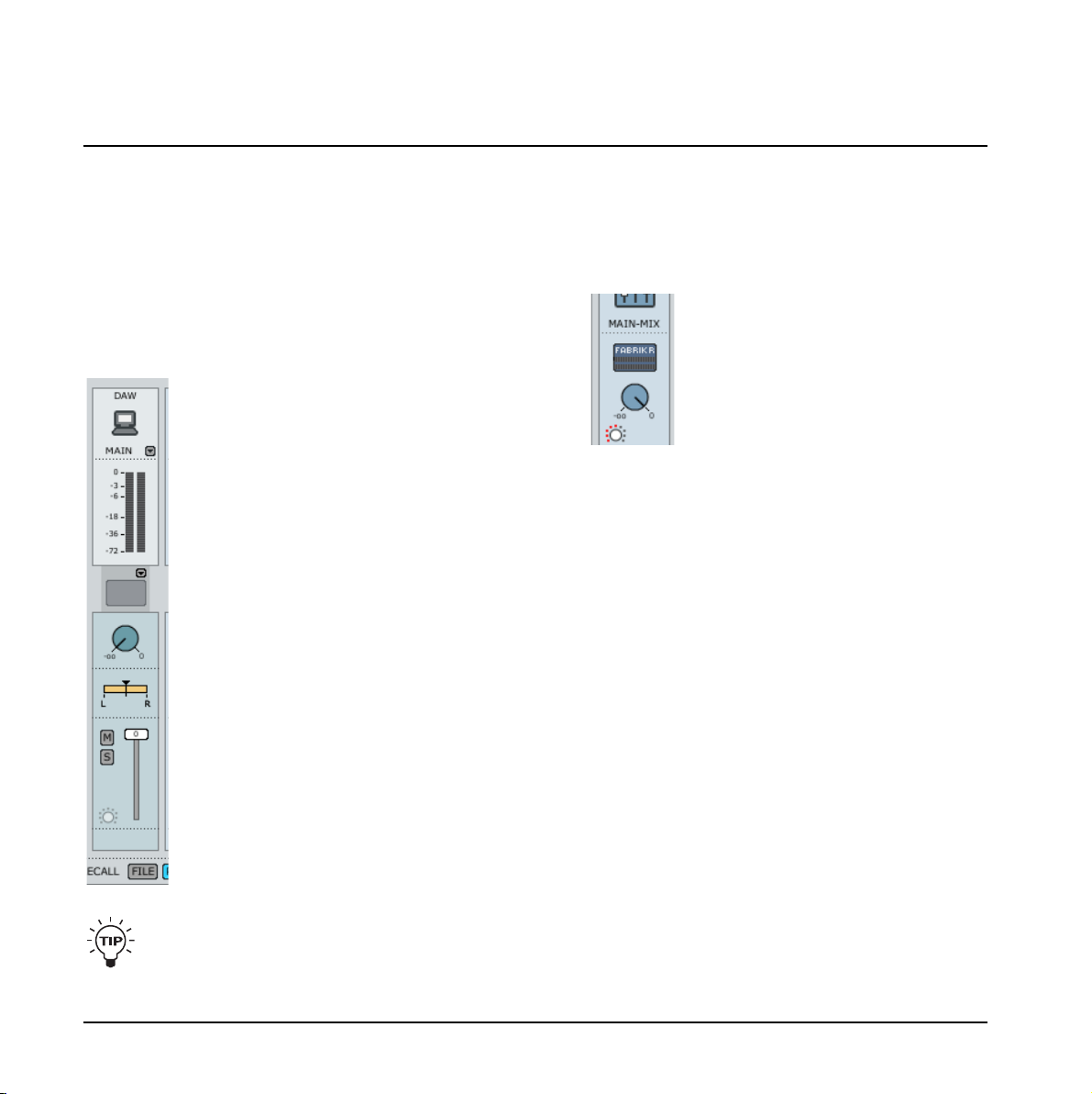
12 DAW Main - meters and fader
This section of the mixer handles the
monitoring of the main outputs from
your DAW. Having the controls at this
place allows you to mix the channels
with the DAW signal, right here on the
Mixer page instead of having to switch
between the programs.
13 Effect Return level - Fabrik R Live
The reverb plug-in Fabrik R Live is set up on a bus
that you can send to from each channel. The return
level of this bus is set using this Effect Return level
controller.
14 Monitor Mixer - Main Out level
This is where you set the output level for the monitor
mixer. The output from the mixer can be sent to any
of the physical outputs (Line 1+2, 3+4, S/PDIF or
ADAT).
THE CONTROL PANEL - MIXER PAGE
16
You can instantly mute a channel by holding
ctrl+shift and click on the fader handle.
11 Digital Channels
The configuration of the digital channels is set via the
Setup page. Please refer to the description on the
following pages.
 Loading...