

Page 1

OPERATOR'S
MANUAL
Model PH61 Heat Treatment
Thick Syrup Shake Freezer
Original Operating Instructions
048119TS 8/5/06 (Original Publication)
(Updated 9/18/14)
Page 2

Complete this page for quick reference when service is required:
Taylor Distributor:
Address:
Phone:
Fax:
E-mail:
Service:
Parts:
Date of Installation:
Information found on the data label:
Model Number:
Serial Number:
Electrical Specs: Voltage Cycle
Phase
Maximum Fuse Size: A
Minimum Wire Ampacity: A
E 2006 Carrier Commercial Refrigeration, Inc.
048119TS
Any unauthorized reproduction, disclosure, or distribution of copies by any person of any portion of this
work maybe a violation of Copyright Law of the United States of Americaand other countries, could result
in the awarding of Statutory Damages of up to $250,000 (17 USC 504) for infringement, and may result
in further civil and criminal penalties. All rights reserved.
Taylor Company
a division of Carrier Commercial Refrigeration, Inc.
750 N. Blackhawk Blvd.
Rockton, IL 61072
Page 3

Table of Contents
Section 1 To the Installer 1............................................
Section 2 To the Operator 4...........................................
Section 3 Safety 6....................................................
Section 4 Operator Parts Identification 8...............................
Model PH61 8..........................................................
Beater and Door Assembly 10.............................................
X57028-XX Pump A. - Mix Simplified 12....................................
Accessories 13..........................................................
Syrup Valve 14..........................................................
X44127 Brush Kit Assembly 15............................................
Section 5 Important: To the Operator 16.................................
Symbol Definitions 16....................................................
Power Switch 17.........................................................
Liquid Crystal Display 17..................................................
Indicator Lights 17.......................................................
Reset Mechanism 17.....................................................
Operating Screen Descriptions 18..........................................
Operator Menu 21.......................................................
Section 6 Operating Procedures 24.....................................
Equipment Set Up 24.....................................................
Daily Closing Procedures 35..............................................
Daily Opening Procedures 38..............................................
Syrup Calibration & Priming 40............................................
Closing Procedures 43...................................................
Draining Product From the Freezing Cylinder 43.............................
Brush Cleaning 47.......................................................
Sanitizing the Syrup Lines 48..............................................
Pump Tube Replacement 49..............................................
PH61 Thick Syrup Table of Contents
Page 4

Table of Contents - Page 2
Section 7 Important: Operator Checklist 52..............................
During Cleaning and Sanitizing 52.........................................
Troubleshooting Bacterial Count: 52........................................
Regular Maintenance Checks: 52..........................................
Winter Storage 53........................................................
Section 8 Troubleshooting Guide 54....................................
Section 9 Parts Replacement Schedule 60...............................
Section 10 Limited Warranty on Equipment 61............................
Section 11 Limited Warranty on Parts 63.................................
Wiring Diagram 66.......................................................
Note: Continuing research results in steady improvements; therefore, information
in this manual is subject to change without notice.
Note: Only instructions originating from the factory or its authorized translation
representative(s) are considered to be the original set of instructions.
E 2006 Carrier Commercial Refrigeration, Inc.
(Updated September, 2014)
048119TS
Any unauthorized reproduction, disclosure, or distribution of copies by any person of any portion of this
work may be a violation of Copyright Law of the United States of Americaand other countries, couldresult
in the awarding of Statutory Damages of up to $250,000 (17 USC 504) for infringement, and may result
in further civil and criminal penalties.
All rights reserved.
Taylor Company
a division of Carrier Commercial Refrigeration, Inc.
750 N. Blackhawk Blvd.
Rockton, IL 61072
PH61 Thick Syrup Table of Contents
Page 5
Section 1 To the Installer
The following information has been included in the
manual as safety and regulatory guidelines. For
complete installation instructions, please see the
Installation Checklist.
Installer Safety
cause severe injuries.
Site Preparation
This unit has many sharp edges that can
In all areas of the world, equipment should
be installed in accordance with existing local codes.
Please contact your local authorities if you have any
questions.
Care should be taken to ensure that all basic safety
practices are followed during the installation and
servicing activities related to the installation and
service of Taylor® equipment.
S Only authorized Taylor service personnel
should perform installation, maintenance,
and repairs on Taylor equipment.
S Authorized service personnel should consult
OSHA Standard 29CFRI910.147 or the
applicable code of the local area for the
industry standards on lockout/tagout
procedures before beginning any installation
or repairs.
S Authorized service personnel must ensure
that the proper protective equipment (PPE)
is available and worn when required during
installation and service.
S Authorized service personnel must remove
all metal jewelry, rings, and watches before
working on electrical equipment.
Review the area where the unit will be installed.
Make sure that all possible hazards to the installer,
user, and the unit have been addressed.
For Indoor Use Only: This unit is designed to
operate indoors, under normal ambient
temperatures of 70°-75°F (21°-24°C). The unit has
successfully performed in high ambient
temperatures of up to 104°F (40°C) at reduced
capacities.
This unit must NOT beinstalledinanarea
where a water jet or hose can be used. NEVER use
a water jet or hose to rinse or clean the unit. Failure
to follow this instruction may result in electrocution.
This unit must be installed on a level surface
to avoid the hazard of tipping. Extreme care should
be taken in moving this unit for any reason. Two or
more persons are required to safely move this unit.
Failure to comply may result in personal injury or
damage to the unit.
The main power supply(s) to the unit must
be disconnected prior to performing any installation,
maintenance, or repairs. Failure to follow this
instruction may result in personal injury or death
from electrical shock or hazardous moving parts as
well as poor performance or damage to the unit.
PH61 Thick Syrup To the Installer
The authorized installer should inspect the unit for
damage and promptly report any damage to the
local authorized Taylor distributor.
This unit is made using USA sizes of hardware. All
metric conversions are approximate and vary in size.
131212
1
Page 6
Air Cooled Units
DO NOT obstruct the unit's air intake and discharge
openings:
Air cooled units require a minimum of 6” (152 mm)
of clearance around all sides of the freezer. Failure
to allow adequate clearance can reduce the
refrigeration capacity of the freezer and possibly
cause permanent damage to the compressors.
In all other areas of the world, the unit should be
installed in accordance with the existing local codes.
Please contact your local authorities.
Each unit requires one power supply for each data
label on the unit. Check the data label(s) on the unit
for branch circuit overcurrent protection or fuse,
circuit ampacity, and other electrical specifications.
Refer to the wiring diagram provided inside of the
electrical box for proper power connections.
Water Connections
(Water Cooled Units Only)
An adequate cold water supply must be provided
with a hand shut-off valve. On the rear of the unit,
two 3/8” I.P.S. water connections for inlet and outlet
have been provided for easy hook-up. 1/2” inside
diameter water lines should be connected to the
machine. (Flexible lines are recommended, if local
codes permit.) Depending on local water conditions,
it may be advisable to install a water strainer to
prevent foreign substances from clogging the
automatic water valve. There will be only one water
“in” and one water “out” connection. DO NOT install
a hand shut-off valve on the water “out” line! Water
should always flow in this order: first, through the
automatic water valve; second, through the
condenser; and third, through the outlet fitting to an
opentrapdrain.
A back flow prevention device is
required on the incoming water connection side.
Please refer to the applicable National, State, and
local codes for determining the proper configuration.
Electrical Connections
In the United States, this unit is intended to be
installed in accordance with the current edition of the
National Electrical Code (NEC), ANSI/NFPA 70
which governs the installation of the unit at the local
governmental level.
The purpose of the NEC code is the practical
safeguarding of persons and property from hazards
arising from the use of electricity. This code contains
provisions considered necessary for safety.
FOLLOW YOUR LOCAL ELECTRICAL CODES!
CAUTION: THIS UNIT MUST BE
PROPERLY GROUNDED! FAILURE TO DO SO
CAN RESULT IN SEVERE PERSONAL INJURY
FROM ELECTRICAL SHOCK!
An equipotential grounding lug is provided with
this unit. Some countries require the grounding lug
be properly attached to the rear of the frame by the
authorized installer. The installation location is
marked by the equipotential bonding symbol (5021
of IEC 60417-1) on both the removable panel and
the unit's frame.
S Stationary appliances which are not
equipped with a power cord and a plug or
another device to disconnect the appliance
from the power source must have an all-pole
disconnecting device with a contact gap of
at least 3 mm installed in the external
installation.
S Appliances that are permanently connected
to fixed wiring and for which leakage
currents may exceed 10 mA, particularly
when disconnected or not used for long
periods, or during initial installation, shall
have protective devices such as a GFI, to
protect against the leakage of current,
installed by the authorized personnel to the
local codes.
2
PH61 Thick SyrupTo the Installer
Page 7
S Supply cords used with this unit shall be
oil-resistant, sheathed flexible cable not
lighter than ordinary polychloroprene or
other equivalent synthetic
elastomer-sheathed cord (Code designation
60245 IEC 57) installed with the proper cord
anchorage to relieve conductors from strain,
including twisting, at the terminals and
protect the insulation of the conductors from
abrasion.
If the supply cord is damaged, it must be
replaced by an authorized Taylor service
technician in order to avoid a hazard.
Beater Rotation
Beater rotation must be clockwise as viewed
looking into the freezing cylinder.
To correct the rotation on a three-phase unit,
interchange any two incoming power supply lines at
unit's main terminal block only.
To correct rotation on a single-phase unit, change
the leads inside the beater motor. (Follow the
diagram printed on the motor.)
Refrigerant
In consideration of our environment, Taylor
uses only HFC refrigerants. The HFC refrigerant
used in this unit is R404A. This refrigerant is
generally considered non-toxic and non-flammable,
with an Ozone Depleting Potential (ODP) of zero (0).
However, any gas under pressure is potentially
hazardous and must be handled with caution.
NEVER fill any refrigerant cylinder completely with
liquid. Filling the cylinder to approximately 80% will
allow for normal expansion.
Use only R404A refrigerant that conforms
to the AHRI standard 700 specification. The use of
any other refrigerant may expose users and
operators to unexpected safety hazards.
Refrigerant liquid sprayed onto the skin may
cause serious damage to tissue. Keep eyes and skin
protected. If refrigerant burns should occur, flush
immediately with cold water. If burns are severe,
apply ice packs and contact a physician
immediately.
Taylor reminds technicians to be aware of
and in compliance with local government laws
regarding refrigerant recovery, recycling, and
reclaiming systems. For information regarding
applicable local laws, please contact your local
authorized Taylor distributor.
Electrical connections are made directly to the
terminal block provided in the main control box
located under the upper left side panel on the
countertop unit, or behind the service panel on the
console units.
It is recommended that beater rotation be performed
by an authorized Taylor service technician.
PH61 Thick Syrup To the Installer
conjunction with polyolester oils are extremely
moisture absorbent. When opening a refrigeration
system, the maximum time the system is open must
not exceed 15 minutes. Cap all open tubing to
prevent humid air or water from being absorbed by
the oil.
3
WARNING: R404A refrigerants used in
131212
Page 8
Section 2 To the Operator
The freezer you have purchased has been carefully
engineered and manufactured to give you
dependable operation. When properly operated and
cared for, it will produce a consistent quality product.
Like all mechanical products, this machine will
require cleaning and maintenance. A minimum
amount of care and attention is necessary if the
operating procedures outlined in this manual are
followed closely.
This Operator's Manual should be read
before operating or performing any maintenance on
your equipment.
The Model PH61 will NOT eventually compensate
and correct for any errors during the set-up or filling
operations. Thus, the initial assembly and priming
procedures are of extreme importance. It is strongly
recommended that personnel responsible for the
equipment's operation, both assembly and
disassembly, study these procedures in order to be
properly trained.
When your machine is delivered or if it has been in
the OFF position for more than 24 hours,
disassemble the freezer following procedures found
on page 43. Follow assembly procedures on
page 24 to re-assemble your machine.
Note: Your Taylor warranty is valid only if the parts
are authorized Taylor parts, purchased from the
local authorized Taylor Distributor, and only if all
required service work is provided by an authorized
Taylor service technician. Taylor reserves the right
to deny warranty claims on units or parts if
non-Taylor approved parts or incorrect refrigerant
were installed in the unit, system modifications were
performed beyond factory recommendations, or it is
determined that the failure was caused by abuse,
misuse, neglect, or failure to follow all operating
instructions. For full details of your Taylor Warranty,
please see the Limited Warranty section in this
manual.
During the heat treatment process, the product is
brought to a temperature sufficient to destroy
bacteria and is returned to a standby temperature.
The special control system will insure that the
product is heated and maintained at the set
temperature for the full 30 minutes. This time is
required to insure that bacteria is destroyed. If the
freezer was unable to complete the heating cycle,
the LCD will read:
“HEAT TREAT CYCLE FAILURE - FREEZER
LOCKED - PRESS SEL KEY”.Ifthisisthecase,or
if you require technical assistance, please contact
your local authorized Taylor Distributor.
Dairy products are susceptible to
bacterial contamination due to improper product
handling. Therefore, be sure to use clean
sanitary conditions when handling mix.
The machine must be disassembled, cleaned,
sanitized, and lubricated every two weeks.
ALWAYS FOLLOW LOCAL HEALTH CODES.
In the event you should require technical assistance,
please contact your local authorized Taylor
Distributor.
131212
If the crossed out wheeled bin symbol is
affixed to this unit, it signifies that this unit is
compliant with the EU Directives as well as other
similar end of life legislation in effect after August
13, 2005. Therefore, it must be collected separately
after its use is completed, and cannot be disposed
as unsorted municipal waste.
The user is responsible for returning the unit to the
appropriate collection facility, as specified by your
local code.
For additional information regarding applicable local
disposal laws, please contact the municipal waste
facility and/or local authorized Taylor distributor.
4
PH61 Thick SyrupTo the Operator
Page 9

Compressor Warranty Disclaimer
The refrigeration compressor(s) on this unit are
warranted for the term stated in the Limited
Warranty section in this manual. However, due to
the Montreal Protocol and the U.S. Clean Air Act
Amendments of 1990, many new refrigerants are
being tested and developed, thus seeking their way
into the service industry. Some of these new
refrigerants are being advertised as drop-in
replacements for numerous applications. It should
be noted that in the event of ordinary service to this
unit's refrigeration system, only the refrigerant
specified on the affixed data label should be
used. The unauthorized use of alternate refrigerants
will void your Taylor compressor warranty. It is the
unit owner's responsibility to make this fact known to
any technician he employs.
It should also be noted that Taylor does not warrant
the refrigerant used in its equipment. For example, if
the refrigerant is lost during the course of ordinary
service to this unit, T aylor has no obligation to either
supply or provide replacement refrigerant either at
billable or unbillable terms. Taylor will recommend a
suitable replacement if the original refrigerant is
banned, obsoleted, or no longer available during the
five (5) year Taylor warranty of the compressor.
From time-to-time Taylor may test new refrigerant
alternates. Should a new refrigerant alternate prove,
through Taylor's testing, that it would be accepted as
a drop-in replacement for this unit, then the
disclaimer in this “Compressor Warranty Disclaimer”
section will not apply to the use of the alternate
refrigerant approved by Taylor.
To find out the current status of an alternate
refrigerant as it relates to your compressor warranty,
call Taylor or your local authorized Taylor distributor.
Be prepared to provide the Model/Serial Number of
the unit in question.
Note: Continuing research results in steady
improvements; therefore, information in this
Operator Manual is subject to change without notice.
131212
PH61 Thick Syrup To the Operator
5
Page 10
Section 3 Safety
We, at Taylor Company, are concerned about the
safety of the operator at all times when they are
coming in contact with the unit and its parts. Taylor
makes every effort to design and manufacture
built-in safety features to protect both operators and
service technicians.
Installing and servicing refrigeration equipment can
be hazardous due to system pressure and electrical
components. Only trained and qualified service
personnel should install, repair, or service
refrigeration equipment. When working on
refrigeration equipment, observe precautions noted
in the literature, tags and labels attached to the unit,
and other safety precautions that may apply. Follow
all safety code requirements. Wear safety glasses
and work gloves.
IMPORTANT - Failure to adhere to the
following safety precautions may result in
severe personal injury or death. Failure to
comply with these warnings may also damage
the unit and/or its components. Such damage
may result in component replacement and
service repair expenses.
DO NOT operate the unit without reading
this entire Operator Manual first. Failure to follow all
of these operating instructions may result in damage
to the unit, poor performance, health hazards,
personal injury, or death.
This unit is to be used only by trained
personnel. It is not intended for use by children or
people with reduced physical, sensory, or mental
capabilities, or lack of experience and knowledge.
Where limited equipment operation is allowed for
public use, such as a self-serve application,
supervision or instruction concerning the use of the
appliance by a person responsible for their safety is
required. Children should be supervised to ensure
that they do not play with the appliance.
S All repairs should be performed by an
authorized Taylor service technician.
S The main power supplies to the unit must be
disconnected prior to performing installation,
repairs, or maintenance.
S DO NOT operate the unit unless it is
properly grounded.
S DO NOT operate the unit with larger fuses
than specified on the unit's data label.
S Units that are permanently connected to
fixed wiring and for which leakage currents
may exceed 10 mA, particularly when
disconnected or not used for long periods,
or during initial installation, shall have
protective devices such as a GFI, to protect
against the leakage of current, installed by
the authorized personnel to the local codes.
S Stationary units which are not equipped with
a power cord and a plug or another device
to disconnect the appliance from the power
source must have an all-pole disconnecting
device with a contact gap of at least 3 mm
installed in the external installation.
S Supply cords used with this unit shall be
oil-resistant, sheathed flexible cable not
lighter than ordinary polychloroprene or
other equivalent synthetic
elastomer-sheathed cord (Code designation
60245 IEC 57) installed with the proper cord
anchorage to relieve conductors from strain,
including twisting, at the terminals and
protect the insulation of the conductors from
abrasion.
If the supply cord is damaged, it must be
replaced by an authorized Taylor service
technician in order to avoid a hazard.
Failure to follow these instructions may result in
electrocution. Contact your local authorized Taylor
Distributor for service.
131212
6
PH61 Thick SyrupSafety
Page 11
An equipotential grounding lug is provided with
this unit. Some countries require the grounding lug
be properly attached to the rear of the frame by the
authorized installer. The installation location is
marked by the equipotential bonding symbol (5021
of IEC 60417-1) on both the removable panel and
the unit's frame.
DO NOT use a water jet to clean or rinse
the unit. Failure to follow these instructions may
result in serious electrical shock.
S DO NOT allow untrained personnel to
operate this unit.
S DO NOT operate the unit unless all service
panels and access doors are restrained with
screws.
S DO NOT remove any internal operating
parts (including, but not limited to, freezer
door, beater, or scraper blades), unless all
control switches are in the OFF position.
Failure to follow these instructions may result in
severe personal injury, especially to fingers or
hands, from hazardous moving parts.
practical experience with the unit, in particular as far
as safety and hygiene are concerned.
Cleaning and sanitizing schedules are
governed by your state or local regulatory agencies
and must be followed accordingly. Please refer to
the cleaning section of this Operator Manual for the
proper procedure to clean this unit.
This unit is designed to maintain product
temperature under 41_F(5_C). Any product being
added to this unit must be below 41_F(5_C). Failure
to follow this instruction may result in health hazards
and poor freezer performance.
DO NOT draw product during the HEAT
cycle because of high product temperatures.
WARNING!
Some consumers are highly allergic to
strawberries. In some severe cases,
strawberry allergic reactions can cause
death. When serving shakes, make sure
the draw handle is closed automatically by
the portion control device and that the
white spot is visible.
This unit has many sharp edges that can
cause severe injuries.
S DO NOT put objects or fingers in the door
spout. This may contaminate the product
and cause severe personal injury from blade
contact.
S USE EXTREME CAUTION when removing
the beater assembly. The scraper blades
are very sharp.
This unit must be placed on a level surface.
Extreme care should be taken when moving the unit
for any reason. Two or more persons are required to
safely move this unit. Failure to comply may result in
personal injury or damage to the unit.
Access to the service area of the unit must
be restricted to persons having knowledge and
DO NOT obstruct air intake and discharge openings:
6” (152 mm) minimum air space on all sides. Failure
to follow this instruction may cause poor freezer
performance and damage to the machine.
For Indoor Use Only: This unit is designed to
operate indoors, under normal ambient
temperatures of 70_-75_F(21_-24_C). The unit has
successfully performed in high ambient
temperatures of up to 104_F(40_C) at reduced
capacities.
DO NOT run the unit without product. Failure to
follow this instruction can result in damage to the
unit.
NOISE LEVEL: Airborne noise emission does not
exceed 78 dB(A) when measured at a distance of
1.0 meter from the surface of the unit and at a
height of 1.6 meters from the floor.
PH61 Thick Syrup Safety
7
Page 12
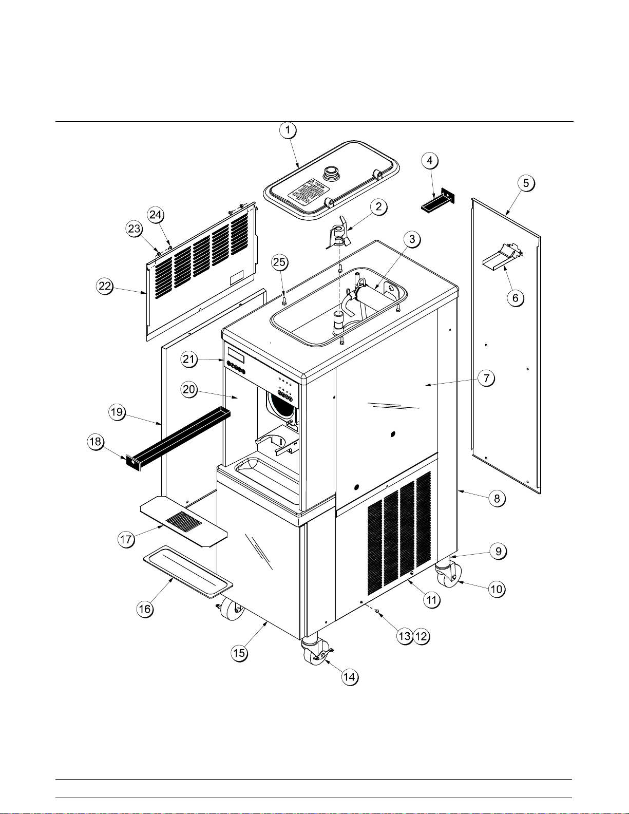
Section 4 Operator Parts Identification
Model PH61
140612
Figure 1
8
PH61 Thick SyrupOperator Parts Identification
Page 13
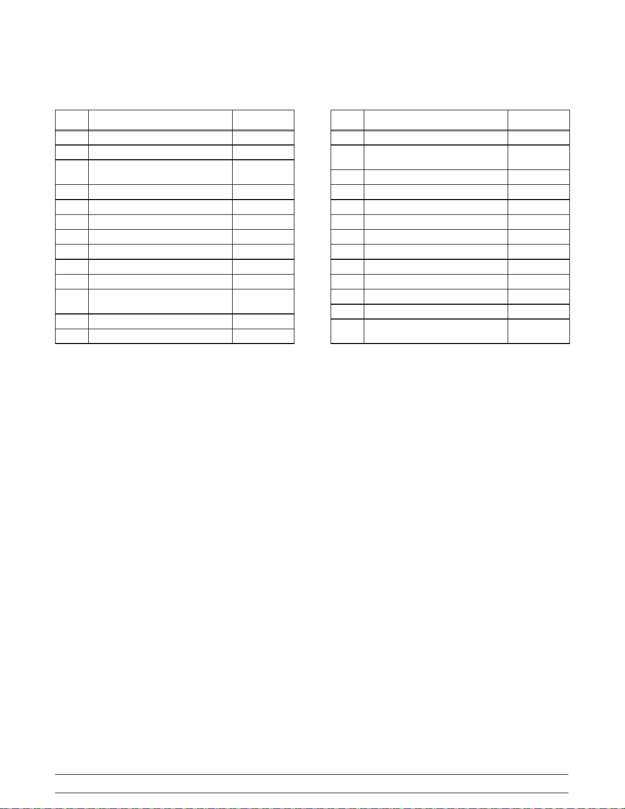
Model PH61-Thick Syrup Parts Identification List
ITEM DESCRIPTION PART NO.
1 KIT A.-COVER-HOPPER X65369
2 AGITATOR X44797
3 PUMP A.-MIX SIMPLIFIED
SHAKE
4 PAN-DRIP-HT 048204
5 PANEL-REAR 048203
6 GUIDE A.-DRIP PAN-MIX PUMP X48228
7 PANEL-SIDE-UPPER-RIGHT 056013
8 TRIM-REAR CORNER RIGHT 045517
* TRIM-REAR CORNER LEFT 045516
9 ADAPTOR A.-CASTER X18915
10 CASTER-SWV 5/8 STEM - 4”
WHEEL
11 PANEL-LOWER·SIDE·RIGHT 034680
12 SCREW-1/4-20X3/8·RHM-SS 011694
X57028-XX
018794
ITEM DESCRIPTION PART NO.
13 FASTENER-CLIP 1/4-20 U 045865
14 CASTER-4" SWV 5/8 STEM
W/BRAKE
15 DOOR A.-SYRUP CABINET X45325
16 TRAY-DRIP 14-7/8L X 5-1/8 SG 013690
17 SHIELD-SPLASH·15"L 022763
18 PAN A.-DRIP X28142
19 PANEL A.-LOWER SIDE X24397-SER
20 PANEL A.-FRONT X55436
21 DECAL-DEC 052280
22 PANEL-SIDE-UPPER-LEFT 056012
23 WASHER-PLASTIC PIVOT 013808
24 SCREW-10-24X1/2TORX TRUS 002077
25 PIN-RETAINING-HOPPER
COVER
*NOT SHOWN
034081
043934
140612
PH61 Thick Syrup Operator Parts Identification
9
Page 14
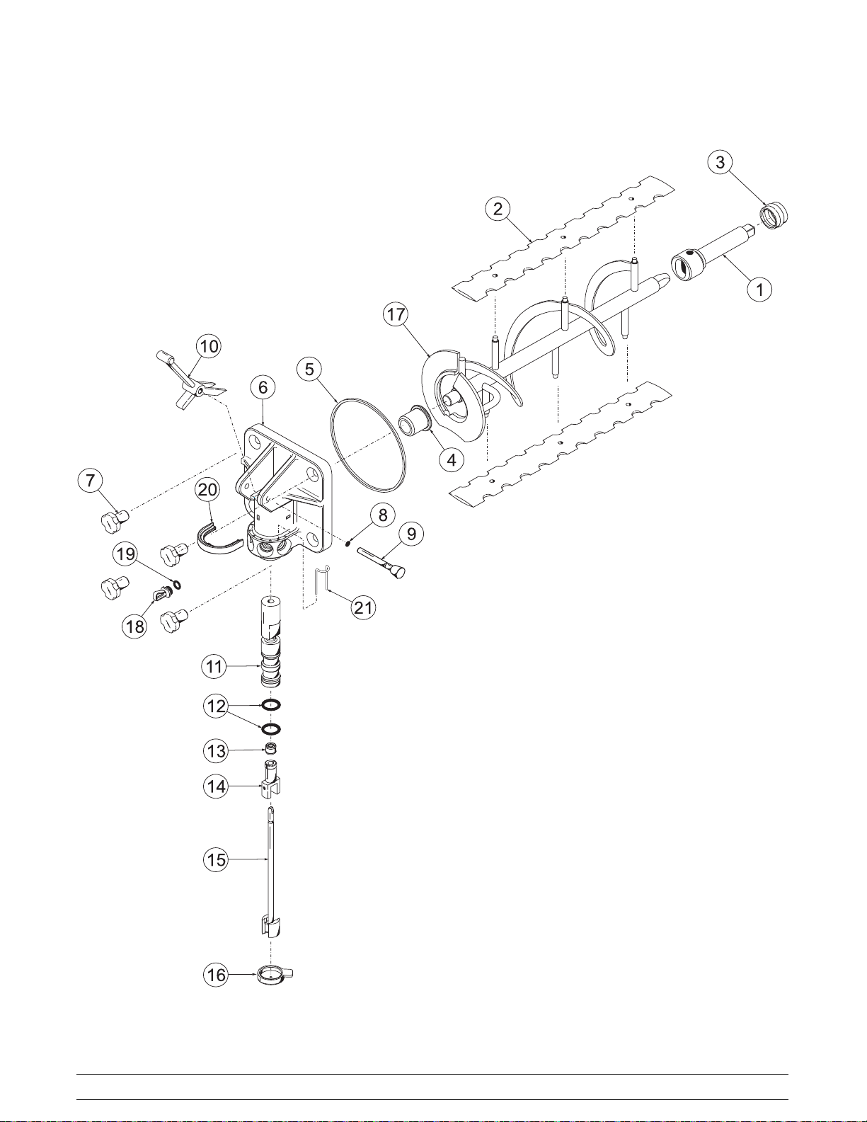
Beater and Door Assembly
Figure 2
10
PH61 Thick SyrupOperator Parts Identification
Page 15
Beater & Door Assembly
ITEM DESCRIPTION PART NO.
1 Shaft-Beater 050985
2 Scraper Blade 041103
3 Drive Shaft Seal 032560
4 Front Bearing 055605
5 O-Ring - Freezer Door 033493
6 Door-TTS Shake 055937
7 Handscrew (Stud Nut)-Shake 034034
8 O-Ring - Pivot Pin 016272
9 Pivot Pin A. X22820
10 Draw Valve Handle 034003
11 Draw Valve Assembly X42210
ITEM DESCRIPTION PART NO.
12 O-Ring - Draw Valve 020571
13 Seal-SpinnerShaft 036053
14 Driven Spinner 034054
15 Blade A.-Spinner X41895
16 Restrictor Cap 033107
17 Beater Assembly- Shake X50958
18 Plug-SyrupPort 053867
19 O-Ring-Syrup Port Plug (Green) 053890
20 Retainer-Valve Pin 054690
21 Retainer-Syrup Valve 054599
PH61 Thick Syrup Operator Parts Identification
11
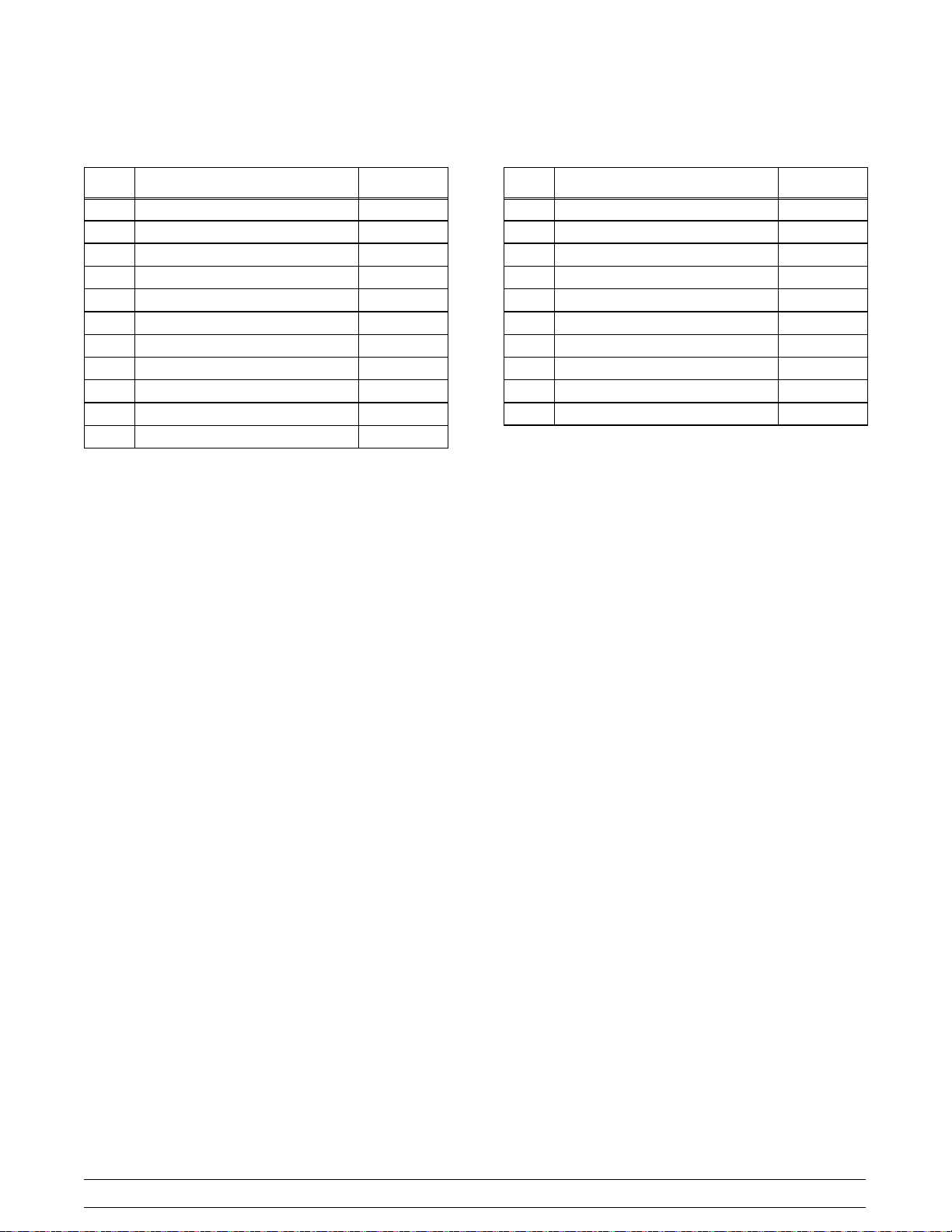
Page 16
X57028-XX Pump A. - Mix Simplified
Figure 3
ITEM DESCRIPTION PART NO.
1-7 PUMP A.-MIX SIMPLIFIED
SHAKE
1 CYLINDER-PUMP HOPPER
SHAKE
2 PIN-RETAINING X55450
3 PISTON-PUMP-SIMPLIFIED 053526
4 O-RING-PKG *50 TO BAG* 020051
5 CAP-VALVE BODY SHAKE 056873-14
6 GASKET-SIMPLIFIEDPUMP
VALVE
7 ADAPTOR-MIX INLET-SHAKE-
BLUE
8 O-RING-PKG *50 TO BAG* 016132-SER
9 PIN-COTTER-HAIRPIN-1/8DIA 044731
X57028-14
057944
053527
054944
ITEM DESCRIPTION PART NO.
10 SHAFT A.-DRIVE-MIX PUMP-
HOPPER
10a CRANK-DRIVE-HOPPER MIX
PUMP
10b SHAFT-DRIVE-MIX
PUMP-HOPPER
10c O-RING-PKG *25 TO BAG* 048632
10d O-RING-PKG *25 TO BAG* 008904
11 CLIP-RETAINER-MIX PUMP 044641
12 TUBE A.-FEED-HOPPER-
SHAKE
13 RING-CHECK-FEED-TUBE 056524
14 SLEEVE A.-MIX PUMP X44761
X41947
039235
041948
X56522
140612
12
PH61 Thick SyrupOperator Parts Identification
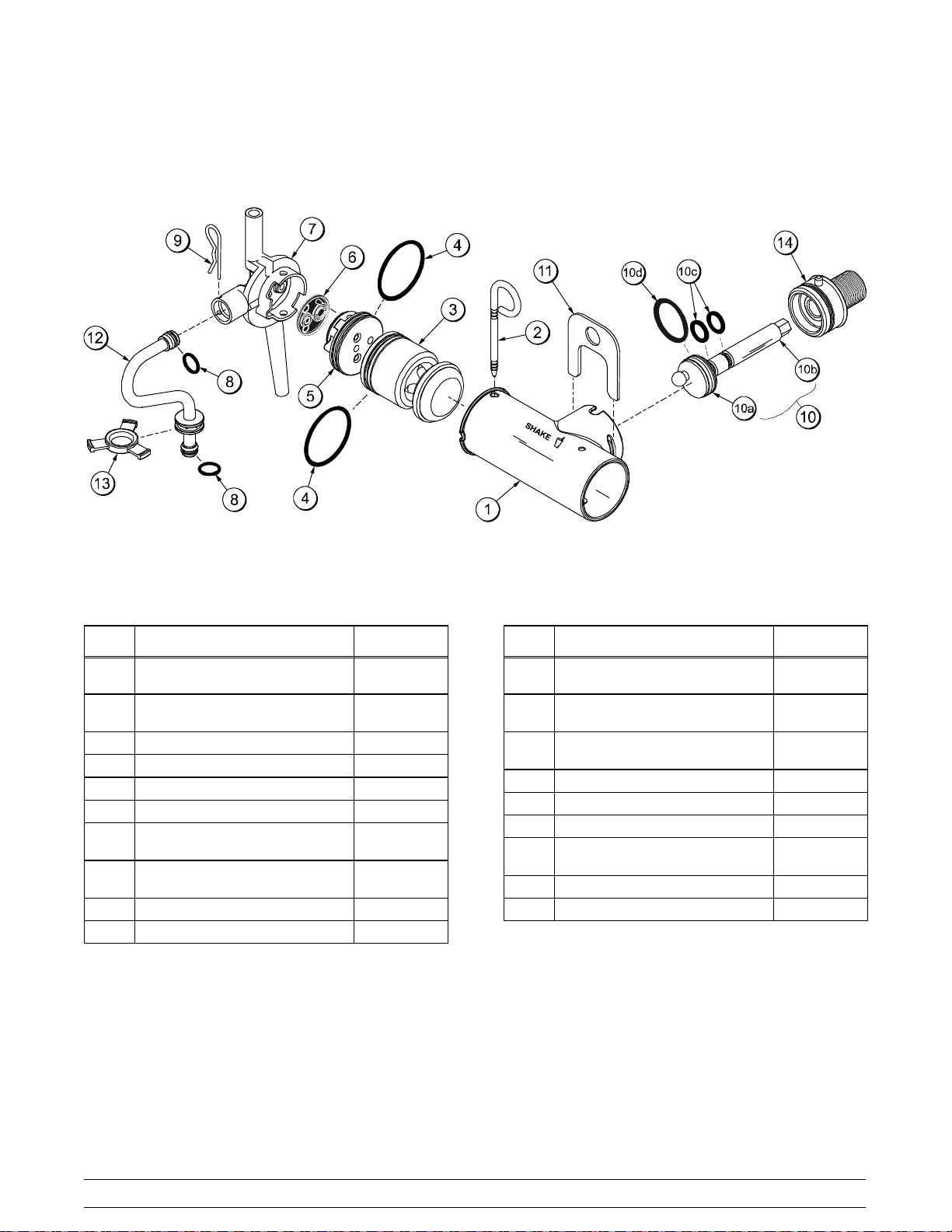
Page 17
Accessories
L
U
B
E
1
R
2
HI
3
KAY-5
Sanitizer/Cleaner
KEEPOUT OF REACH OF CHILDREN
FOR INSTITUTIONALUSE ONLY
CAUTION
1 OZ (28.4 g)
®
4
5
6
Figure 4
ITEM DESCRIPTION PART NO.
1 SANITIZER KAY-5 (125 PACKS) 041082
2 LUBRICANT-TAYLOR HI-PERF. 048232
3 PAIL-10 QT. 013163
4 BOTTLE A.-SQUEEZE 044818
5 TOOL-SHAFT-DRIVE PUMP
HPR/LVB
6 TOOL-SHAFT-DRIVE PUMP HPR 057167
047919
PH61 Thick Syrup Operator Parts Identification
ITEM DESCRIPTION PART NO.
*7 KIT A.-PARTS TRAY SIMPL PMP
(consists of 056525 & 044118)
*8 KIT A.-ACCESSORY PH61 X48127
*9 KIT-TUNE UP SIMPL PUMP X49463-64
*10 KIT A.-RETAINER HOLDER X54560
*11 KIT A.-PERISTALTIC PUMP X54978
*12 KIT A.-SYRUP PLUG KIT TTS X58474
*NOT SHOWN
13
X58447
140718
Page 18
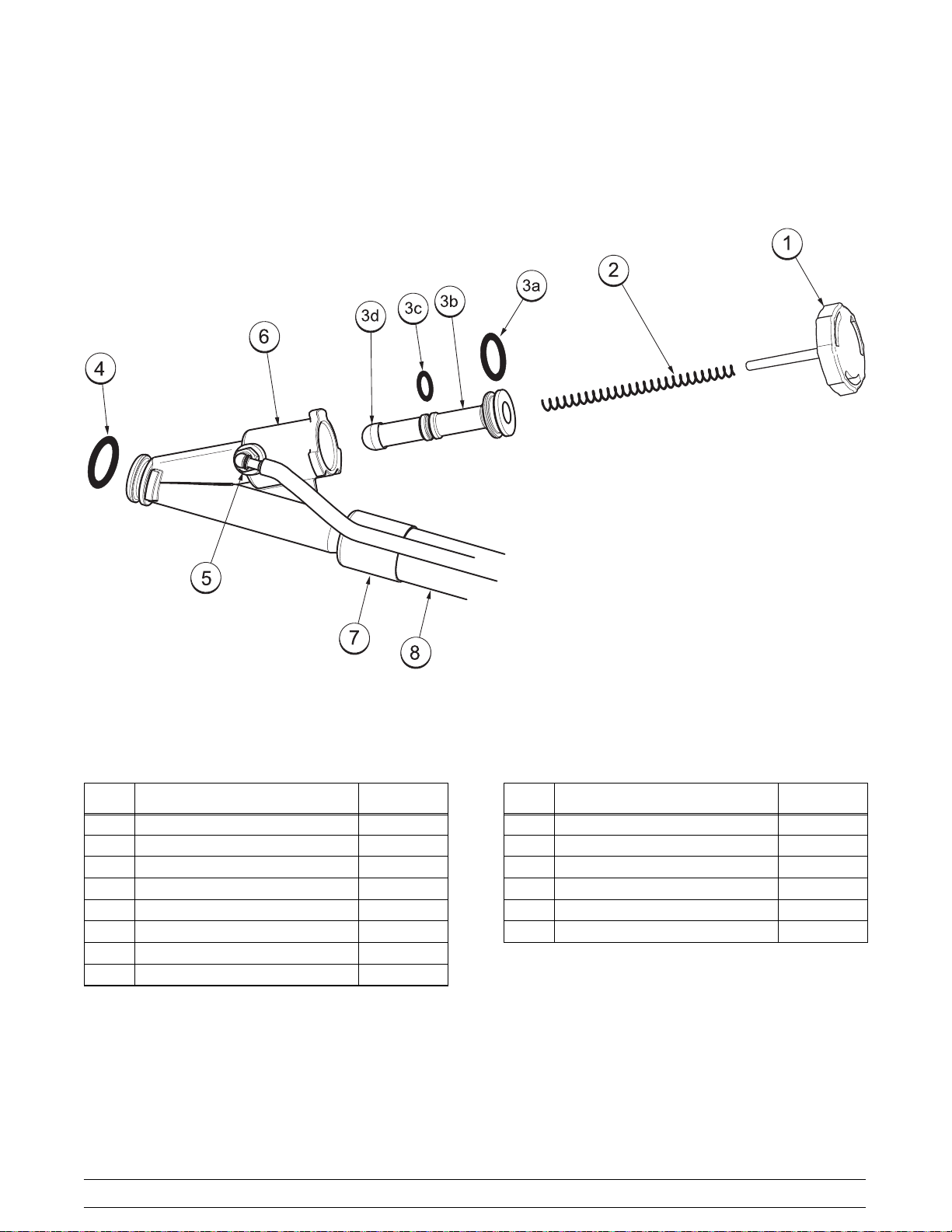
Syrup Valve
ITEM DESCRIPTION PART NO.
1-6 Valve-Syrup 053874
1 Cap-Syrup Valve 053874-001
2 Spring-Syrup Valve 053874-003
3 Plunger-Syrup Valve w/Seals 053874-009
3a O-Ring-Syrup Valve Plunger L 053874-007
3b Plunger-Syrup 053874-002
3c O-Ring-Syrup Valve Plunger S 053874-006
3d Seal-SyrupValve Plunger 053874-008
Figure 5
14
ITEM DESCRIPTION PART NO.
4 O-Ring-11MM x 2MM 053890
5 Fitting-Syrup Valve 053874-004
6 Body-SyrupValve 053874-005
7 Ferrule-.625ID Brass 053036
8 Tube-Twinned Syrup 054580-86
* KitA.-Repair Valve 054595
*Not Shown
PH61 Thick SyrupOperator Parts Identification
Page 19
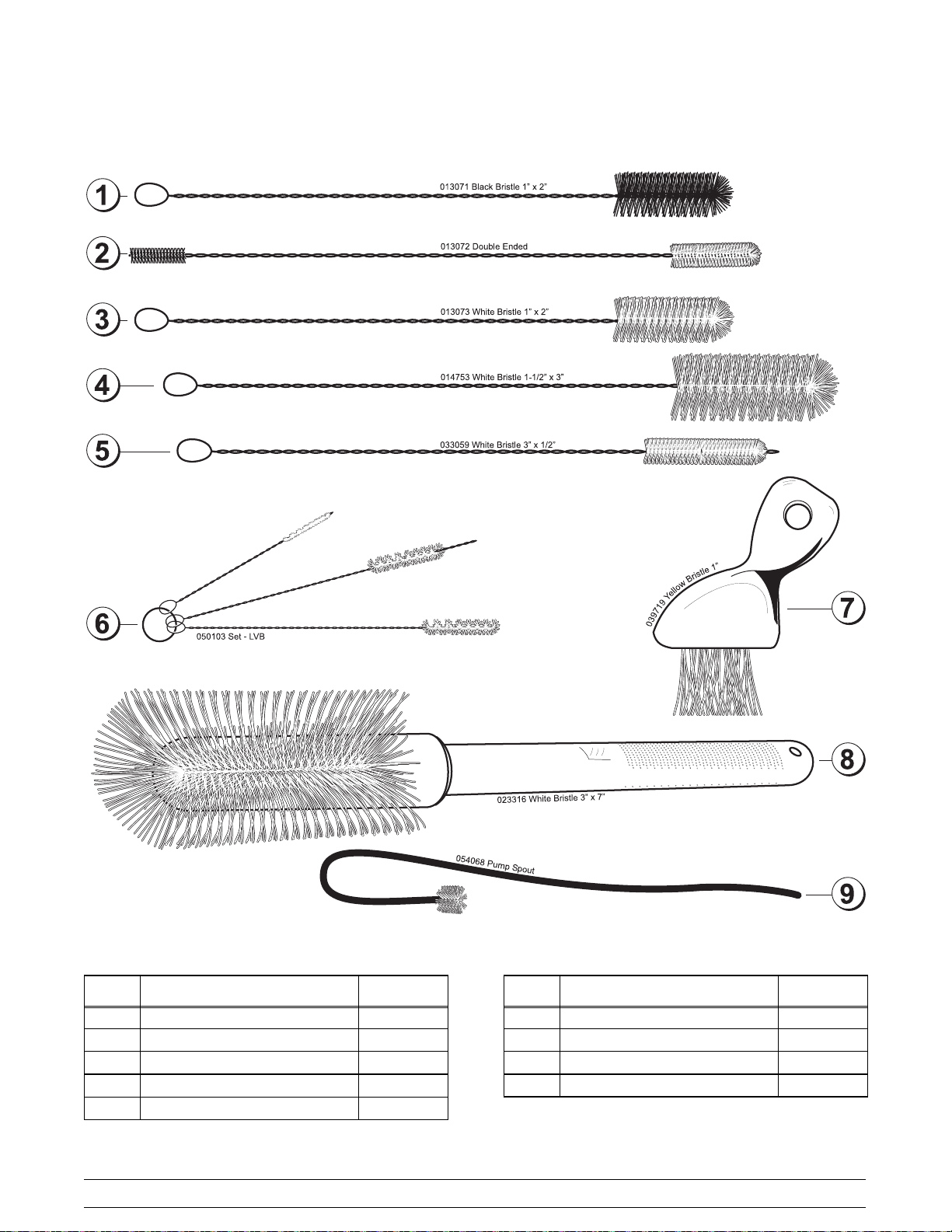
X44127 Brush Kit Assembly
Figure 6
ITEM DESCRIPTION PART NO.
1 Black BristleBrush 013071
2 Double End Brush 013072
3 WhiteBristleBrush(1”x2”) 013073
4 White Bristle Brush (1-1/2” x 3”) 014753
5 White Bristle Brush (1/2” x 3”) 033059
PH61 Thick Syrup Operator Parts Identification
ITEM DESCRIPTION PART NO.
6 Brush Set (3) 050103
7 Yellow Bristle Brush 039719
8 White Bristle (3” x 7”) 023316
9 Brush-Pump Spout 054068
15
Page 20
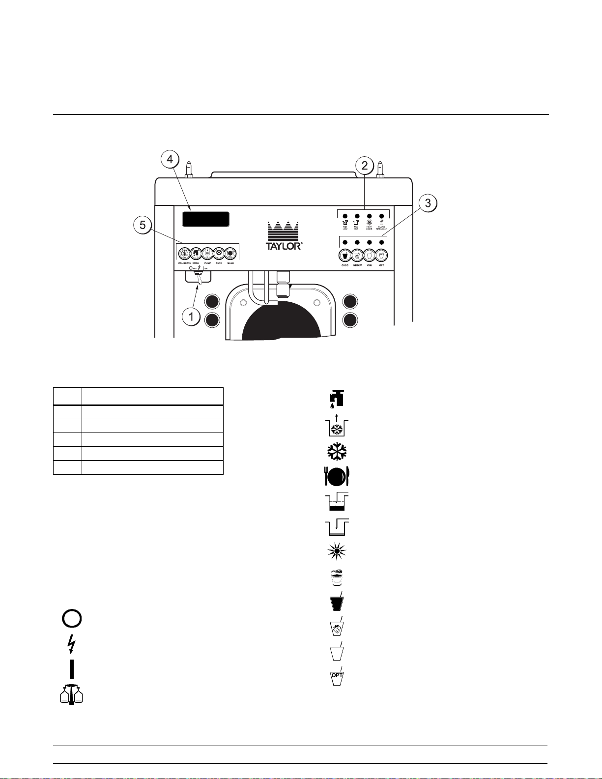
Section 5 Important: To the Operator
Item Description
1 Power Switch
2 Indicator Lights
3 Flavor Selector Keypad
4 Liquid Crystal Display
5 Keypads
Symbol Definitions
To better communicate in the International arena,
the words on many of our operator switches and
buttons have symbols to indicate their functions.
Your Taylor equipment is designed with these
International symbols.
The following chart identifies the symbol definitions
used on the operator switches.
=OFF
=POWER
=ON
= WASH
=PUMP
=AUTO
=MENU
=MIXLOW
= MIX OUT
= HEAT MODE
= CLEAN MANUALLY/BRUSH CLEAN
= CHOCOLATE
= STRAWBERRY
= VANILLA
= OPTIONAL
=CALIBRATE
16
PH61 Thick SyrupImportant: To the Operator
Page 21

Power Switch
The power switch is located under the control panel
on the left hand side of the unit. When placed in the
ON position, the power switch allows softech panel
operation.
Liquid Crystal Display
The Liquid Crystal Display (LCD) is located on the
front control panel. The LCD is used to show in what
mode the freezer is operating and whether or not
there is sufficient mix.
Indicator Lights
MIX LOW - When the MIX LOW light begins to
flash, it indicates the mix hopper has a low supply of
mix and should be refilled as soon as possible. The
word “LOW” will also display on the LCD indicator
next to the word “MIX”.
MIX OUT - When the MIX OUT light begins to flash,
it indicates the mix hopper has been almost
completely exhausted and has an insufficient supply
of mix to operate the freezer. The word “OUT” will
also display on the LCD indicator next to the word
“MIX”. At this time, the AUTO mode is locked out
and the freezer will be placed in the STANDBY
mode. To initiate the refrigeration system, add mix to
the mix hopper and press the AUTO keypad. The
freezer will automatically begin operation.
HEAT MODE - When the HEAT MODE light is
flashing, it indicates that the freezer is in the process
of a heat cycle.
CLEAN MANUALLY - When the CLEAN
MANUALLY light is flashing, it indicates that the
machine must be disassembled and brush cleaned
within 24 hours.
When all four indicator lights are flashing, this
signifies a locked condition. Once a hard lock
condition has been remedied, two lights will remain
flashing until the mix low and mix out conditions
have been satisfied. During a soft lock condition, all
four lights will stop flashing once the unit has been
placed in a heat cycle.
Reset Mechanism
The reset button is located in the right side panel.
The reset mechanism protects the beater motor
from an overload condition. Should an overload
occur, the reset mechanism will trip. To properly
reset the freezer, place the power switch in the OFF
position. Press the reset button firmly. Turn the
power switch to the ON position. Clear the fault.
Press the WASH keypad and observe the freezer's
performance. Open the side access panel to check if
the beater motor is turning the drive shaft in a
clockwise (from the operator end) direction without
binding.
Note: Do not use metal objects to press
the reset button. Failure to follow this instruction
may result in serious electrical shock.
If the beater motor is turning properly, press the
WASH keypad to cancel the cycle. Press the AUTO
keypad to resume normal operation. If the freezer
shuts down again, contact a service technician.
PH61 Thick Syrup Important: To the Operator
17
Page 22

Operating Screen Descriptions
When the machine is powered the system will
initialize. The screen will display “INITIALIZING”.
There will be four types of data the system will
check: LANGUAGE, SYSTEM DATA, CONFIG
DATA, and LOCKOUT DATA. During the
INITIALIZING... LANGUAGE screen, the alarm will
be on. If the system data, configuration data, or
lockout history data has become corrupt, the
following screen will alert the operator that the
system settings may have been changed.
NVRAM FAULT
RESET TO DEFAULTS
PRESS SEL KEY
POWER SWITCH OFF
-=-=-=-=-=UNIT CLEANED
When the power switch is set in the ON position, the
system mode of operation screen is displayed. In
this example, the machine is ON, but no mode of
operation has been selected. The second line of the
display indicates whether there is a sufficient supply
of mix in the hopper or if there is a LOW or OUT mix
condition. The third line of the display shows the
temperature of the mix hopper. After pressing the
AUTO keypad, the last line of the display shows the
month and date (MM = month, DD = day) that the
machine needs to be disassembled and brush
cleaned.
Once the system has initialized the SAFETY
TIMEOUT screen is displayed and the alarm is
turned on.
SAFETY TIMEOUT
ANY KEY ABORTS
This screen will be displayed, with the alarm on, for
60 seconds or until any keypad is pressed.
After the safety timeout has been completed, and
the power switch is OFF, one of the following
screens is displayed.
The first screen is displayed if the machine is not in
a brush clean state. If any of the requirements for a
brush clean have not been met, the time displayed
will remain at 5:00 minutes. When all the
requirements for a brush cleaning are met, and the
five minutes expire, the screen will change to the
second screen, which is the standard power switch
OFF screen.
MODE: OFF
HOPPER TEMP: 35.5F
UNIT CLEANED
The next display indicates the freezer is operating in
two different modes. The following information is
given:
The machine is operating in the WASH and PUMP
modes, the temperature of the mix hopper is 40_F
(4.4_C), and the machine needs to be brush cleaned
on October 31st.
MODE: WSH-PMP
HOPPER TEMP: 40.0 F
BRUSH CLEAN ON: 10/31
The following displays pertain to the HEAT cycle:
While in the heating phase, you will see this display.
It shows the present temperature of the hopper.
TIME: 4:40
HOPPER: 62.1
BARREL: 67.7
POWER SWITCH OFF
18
MODE: HEAT
PHASE: HEAT
HOPPER TEMP: 140.0 F
BRUSH CLEAN ON: MM/DD
PH61 Thick SyrupImportant: To the Operator
Page 23

The mix temperature must be raised above 151_F
(66.1_C) within 90 minutes or the freezer will be
locked in STANDBY, and the cycle failure display
will appear.
In the example, the hopper temperature is 140_F
(60_C). The phase shows that the machine is in the
heat phase of the heat treatment cycle.
When the heating phase is complete, the freezer
goes into the holding phase of the cycle. The holding
phase will hold the temperature above 151_F
(66.1_C) for a minimum of 30 minutes.
In this example, the hopper temperature is 151_F
(66.1_C).
Hard Lock: There are two causes for a hard lock:
1. Fourteen days have elapsed since the last
brush cleaning. The following screen will be
displayed.
14 DAY TIMEOUT
CLEANING REQ'D
FREEZER LOCKED
PRESS SEL KEY
2. There has been a thermistor failure (freezing
cylinder, hopper, or glycol) during the heat
treatment process.
MODE: HEAT
PHASE: HOLD
HOPPER TEMP: 151.0 F
BRUSH CLEAN ON: MM/DD
The final phase of the heat treatment cycle is the
cooling phase. Now the freezer must cool the mix
below 41_F(5_C). If the product fails to cool in two
hours, the freezer will lock out.
This example illustrates that the temperature is
being lowered, but has not yet reached the set point.
MODE: HEAT
PHASE: COOL
HOPPER TEMP: 55.0 F
BRUSH CLEAN ON: MM/DD
The entire heat treatment cycle must be completed
in four hours.
When the entire heat cycle has been completed, the
normal display will appear, showing the machine in
the STANDBY mode. The machine may now be
placed in the AUTO mode or left in the STANDBY
mode.
SYSTEM FAULT
SERVICE REQ'D
FREEZER LOCKED
PRESS SEL KEY
All four LED's on the front of the freezer will light.
Press the SEL keypad.
The next display is the screen which will appear
after the failure message. To comply with health
codes, heat treatment system freezers must
complete a heat treatment cycle daily, and must
also be brush cleaned every 14 days. Brush
cleaning is the normal disassembly and cleaning
procedures. Failure to follow these guidelines will
cause the control to lock the freezer out of the
AUTO mode. Press the WASH keypad.
NO AUTO OPERATION
ALLOWED UNTIL
BRUSH CLEANING
PRESS WASH KEY
The next display is the screen which will appear
after the brush cleaning message and illustrates that
the control is in the OFF mode and the machine
needs to be disassembled and brush cleaned.
MODE: STANDBY
HOPPER TEMP: 41.0 F
BRUSH CLEAN ON: MM/DD
PH61 Thick Syrup Important: To the Operator
19
MODE: OFF
HOPPER TEMP: 45.0 F
FREEZER LOCKED
Page 24

Soft Lock: If a heat treatment cycle has not been
initiated within the last 24 hours, all four LED's on
the front of the machine will light and a message will
appear on the LCD. Line 3 of the LCD will indicate
the reason the message appears. Following are the
variable messages which will appear on line 3:
1. POWER SWITCH OFF: Power switch was in
the OFF position.
2. MIX OUT PRESENT: There was mix out
condition present.
3. AUTO OR STANDBY OFF: The unit was not
in the AUTO or STANDBY mode.
4. NO HEAT CYCLE TRIED: A heat treatment
cycle was not attempted in the last 24 hours.
(AUTO HEAT TIME was advanced, or a power
loss was experienced at the time the cycle was
to occur, or a heat cycle failure not due to a
thermistor failure.)
Press the SEL keypad to advance to the next
display.
When one of these messages appears, automatic
freezer operation cannot take place until the freezer
is disassembled and brush cleaned or has
completed a heat treatment cycle. The next display
will instruct the operator to start a heat treatment
cycle manually (by pressing the AUTO keypad), or
to disassemble and brush clean the freezer. If the
AUTO keypad is pressed, the freezer will
automatically start the heat treatment cycle and only
the heat cycle LED will light.
NO AUTO OPERATION
ALLOWED. PRESS
AUTO FOR HEAT CYCLE
WASH TO BRUSH CLEAN
NO HEAT TREAT START
BECAUSE
VARIABLE MESSAGE
PRESS SEL KEY
If the following screen appears, a soft lock has
occurred during the heat treatment cycle.
HEAT TREAT CYCLE
FAILURE
FREEZER LOCKED
PRESS SEL KEY
If the temperature of the product has not fallen
below 41_F(5_C) by the end of the COOL cycle, the
following screen will appear.
PRODUCT OVER TEMP
FREEZER LOCKED
PRESS SEL KEY
If the WASH keypad is pressed, the next display will
appear and the freezer will have to be disassembled
and brush cleaned.
MODE: OFF
HOPPER TEMP: 41.0F
FREEZER LOCKED
Once the freezer is unlocked by starting a heat
treatment cycle, only the heat cycle LED will light. If
the freezer is unlocked by brush cleaning, the mix
low and mix out LED's will light.
20
PH61 Thick SyrupImportant: To the Operator
Page 25

Operator Menu
The OPERATOR MENU is used to enter the
operator function displays. To access the
OPERATOR MENU, simply press the MENU
keypad. The cursor will flash over the letter “A”
indicating that this is screen “A”. To select a different
screen, use the arrow keypads and move the cursor
to the desired screen selection and press the SEL
keypad.
OPERATOR MENU
BCDEFGHIJ
EXIT FROM MENU
<--- ---> SEL
Screen “B” is FAULT DESCRIPTION. The fault
description will indicate if there is a fault with the
freezer and the side of the freezer where the fault
occurred. To clear the tone for any faults which have
been corrected, press the left arrow keypad. To see
if there is more than one fault per cylinder, press the
SEL keypad. When the last fault is displayed, the
control will return to the OPERATOR MENU. To
return to the main screen, move the cursor to “A”
and press the SEL keypad again. Listed below are
the variable messages which will appear, along with
thecorrectiveaction:
1. NO FAULT FOUND: There was no fault found
in the freezer. Nothing will appear on the
screen after this variable message appears.
A
7. GLYCOL THERM BAD: Place the power
switch in the OFF position. Call service
technician.
8. HOPPER OVER TEMP: The hopper
temperature has risen too high as follows. Clear
the tone.
a. The hopper temperature reaches 41_F
(5_C) or higher after a power failure.
b. The hopper temperature has not fallen
below 41_F(5_C) by the end of the COOL
phase in the heat cycle.
9. BARREL OVER TEMP: The barrel temperature
has risen too high as follows. Clear the tone.
a. The barrel temperature reaches 41_F
(5_C) or higher after a power failure.
b. The barrel temperature has not fallen
below 41_F(5_C) by the end of the COOL
phase in the heat cycle.
10. POWER FAILURE: This message will appear
in the FAULT DESCRIPTION if a power failure
has occurred. Clear the tone.
FAULT DESCRIPTION
VARIABLE MESSAGE
CLR SEL
2. BEATER OVERLOAD: Press the reset button
firmly. Clear the tone.
Screen “C” is SET CLOCK. This screen will display
the current date and time. The date and time may
3. CHK REFRIG SYS PSI: Place the power
switch in the OFF position. Wait 5 minutes for
the machine to cool. Place the power switch in
the ON position. Clear the tone.
4. COMP ON TOO LONG: Place the power
switch in the OFF position. Call service
technician. Clear the tone.
only be changed after the freezer has been manually
brush cleaned but before it has been placed in the
AUTO mode. Move the cursor under the number
you wish to change. Press the plus keypad to
increase the number; press the minus keypad to
decrease the number. When the desired time and
date appears, press the SEL keypad once to return
to the OPERATOR MENU.
5. HOPPER THERM BAD: Place the power
switch in the OFF position. Call service
technician.
6. BARREL THERM BAD: Place the power
switch in the OFF position. Call service
SET CLOCK
10:21 AM 11/07/2006
-<--- ---> +++ --- SEL
technician.
PH61 Thick Syrup Important: To the Operator
21
Page 26

If an illegal date is entered, the following screen will
appear. The correct date must be entered before
leaving this display.
SET CLOCK
10:34 AM 02/30/2006
- - INVALID DATE
<--- ---> +++ --- SEL
Screen “D” is SYSTEM INFORMATION. The first
screen will indicate the software version used in the
unit.
Screen “F” is CURRENT CONDITIONS. This screen
gives the viscosity of the product and the hopper
and barrel temperatures. The last line of the display
is the compressor countdown safety timer. The
safety timer prevents the compressor from running
more than 11 minutes (other than during the cooling
phase of the heat treatment cycle).
Press the SEL keypad once to view the SERVINGS
COUNTER screen.
VISC HOPPER BARREL
0 38.5 28.5
SOFTWARE VERSION
PH61 Control UVC2
Version 2.00
SEL
Press the SEL keypad to view the second screen of
the SYSTEM INFORMATION display. This screen
will indicate the Bill of Material number and serial
number for the unit. Press the SEL keypad once to
return to the Operator Menu.
B.O.M. PH6158BAGS
S/N K0000000
SEL
Screen “E” is AUTO HEAT TIME. This screen is
used to set the time of day in which the heat
treatment cycle will start. Move the cursor under the
number you wish to change. Press the plus keypad
to increase the number; press the minus keypad to
decrease the number. When the desired time
appears, press the SEL keypad once to return to the
OPERATOR MENU.
AUTO HEAT TIME
TIME: 12:00 AM
--
<--- ---> +++ --- SEL
TIME C 11:00 11:00
The SERVINGS COUNTER screen indicates the
number of times the draw switch has closed
(number of draws) since the last brush cleaning or
since the last serving counter reset. A maximum of
32,767 draws can be recorded; an additional draw
will cause the counter to restart at zero. Pressing the
MENU keypad/SEL will return the display to the
Operator Menu.
SERVINGS COUNTER
DRAWS
12
SEL
Draws are counted during the AUTO mode of
operation only.
Screen “G” is HEAT CYCLE DATA. The information
from the previous heat treatment cycles can be
obtained through this screen. The most recent heat
treatment cycle data will be shown first; press the
plus keypad to scroll through the remaining heat
cycle displays. If a heat treatment cycle failure
should occur, a 2 character message will appear on
the second line of the screen. Press the SEL keypad
once to return to the OPERATOR MENU.
22
PH61 Thick SyrupImportant: To the Operator
Page 27

Listed below are the variable messages which could
appear:
HT Failure in the heating phase.
CL Failure in the cooling phase.
TT Failure in meeting total heat treatment cycle
time requirement.
MO Mix out condition.
OP Operator interruption.
PF Power failure. (If a power failure occurs, but
the heat treatment cycle does not fail, an
asterisk (*) will appear on the third line of the
display.)
BO Beater overload.
HO High pressure cut-out.
TH Failed thermistor probe.
PS Power switch placed in the OFF position.
ML Mix Low Condition.
14 14 Day Timeout Occurred.
RC Heat Cycle Record Cleared.
Screen “H” is the LOCKOUT HISTORY. This screen
displays a history of the last 40 hard locks, soft
locks, and brush clean dates. Page numbers are
indicated in the upper right hand corner. Page 1
always contains the most recent failure. Press the
PUMP keypad to cycle through the pages.
The second line of the screen displays the date and
time a failure occurs. The third line indicates the
reason for a failure, or will indicate a successful
brush cleaning has occurred. Some failures occur
for multiple reasons. When this occurs, a page will
be generated for each reason. Press the SEL
keypad once to return to the Operator Menu, or
twice to return to the Main Screen.
LOCKOUT HISTORY 1
11/21/06 02:08
SOFTLOCK ABORT
+++ - - - SEL
11/07 02:00 05:09
HEAT OVER COOL XX
01:09 00:45 01:14
TEMP AT END 38.5 1
Pressing the left arrow keypad on any HEAT CYCLE
DATA screen will cause the extended data screen to
be displayed. This screen shows the hopper, barrel,
and glycol temperatures, and the amount of time the
freezer spent in the phases of the heat cycle when
the heat cycle completed, or was terminated.
HOPPER BARREL GLYCOL
151.0 134.5 178.0
PHASE TIME: 1:20 1
Screen “I” is the SERVICE MENU. This screen can
only be accessed by a service technician.
Screen “J” is the STANDBY MODE. To place the
freezer in the STANDBY mode, move the cursor
under the word “yes”. Press the SEL keypad to
execute the command. Pressing the SEL keypad
again will return you to the main screen. To exit the
STANDBY mode and place the unit in AUTO, press
the AUTO keypad once. Pressing the AUTO keypad
again will place the unit in the OFF mode.
STANDBY MODE
STANDBY YES NO
---
<--- ---> SEL
PH61 Thick Syrup Important: To the Operator
23
Page 28

Section 6 Operating Procedures
Equipment Set Up
Evaluate the condition of lights and screen
messages (Hard Lock or Soft Lock, etc.) before
performing opening procedures. If all four LED's on
the front of the unit are lit, the unit is locked.
(See Figure 7.)
Figure 7
Freezing Cylinder Assembly
Make sure the power switch is in the
OFF position. Failure to follow this instructionmay
result in severe personal injury from hazardous
moving parts.
With the parts tray available:
Step 1
Before installing the shake beater drive shaft,
lubricate the groove on the beater drive shaft. Slide
the beater drive shaft boot seal over the small end of
the beater drive shaft and engage into the groove on
the shaft. Heavily lubricate the inside portion of the
boot seal and also lubricate the flat end of the boot
seal that comes in contact with the rear shell
bearing.
Apply an even coat of lubricant to the shaft. DO
NOT lubricate the square end. (See Figure 8.)
Note: When lubricating parts, use an approved food
grade lubricant (example: Taylor Lube HP).
We begin our instructions at the point where we
enter the store in the morning and find the parts
disassembled and laid out to air dry from the
previous night's cleaning.
These opening procedures will show you how to
assemble these parts into the freezer, sanitize them,
and prime the freezer with fresh mix in preparation
to serve your first portion.
If you are disassembling the machine for the first
time or need information to get to the starting point
in our instructions, turn to the Closing Procedures on
page 43, and start there.
Figure 8
24
PH61 Thick SyrupOperating Procedures
Page 29

Note: To ensure that the mix does not leak out of
the back of the freezing cylinder, the middle section
of the boot seal should be convex or extend out from
the seal. If the middle section of the boot seal is
concave or extending into the middle of the seal,
turn the seal inside out. (See Figure 9.)
Step 4
If blades are in good condition, place each scraper
blade over the holding pins on the beater assembly.
(See Figure 11.)
Figure 9
Step 2
Install the beater drive shaft through the rear shell
bearing in the freezing cylinder and engage the
square end firmly into the drive shaft coupling. Be
sure the drive shaft fits into the drive coupling
without binding. (See Figure 10.)
Figure 10
Step 3
Check scraper blades for any nicks or signs of wear.
If any nicks are present, replace the blades.
Figure 11
Note: The holes in the scraper blade must fit over
the pins to prevent damage.
Step 5
Hold the blades on the beater assembly. Insert the
back of the beater assembly into the freezing
cylinder and connect the drive hole with the drive
shaft. (See Figure 12.)
Figure 12
Note: Scraper blades should be replaced every 6
months.
PH61 Thick Syrup Operating Procedures
Note: When properly seated, the beater will not
protrude beyond the front of the freezing cylinder.
25
Page 30

Step 6
Place the freezer door o-ring into the groove on the
back of the freezer door. DO NOT lubricate the
o-ring. Lubricate the outside diameter of the front
bearing. Slide the front bearing into the door hub.
(See Figure 13.)
11272
Figure 13
Step 7
Install the freezer door. Position the freezer door on
the 4 studs on the front of the freezing cylinder.
Install the handscrews. Tighten equally in a
criss-cross pattern to insure the door is snug. Do
not over-tighten. (See Figure 14.)
Step 8
Assemble the draw valve spinner assembly. Inspect
draw valve o-rings for cuts or nicks. (Replace if cut
or nicked.) If draw valve o-rings are in good
condition, slide the 2 o-rings into the grooves of the
draw valve and lubricate. (See Figure 15.)
Figure 15
Step 9
Lubricate the outer diameter of the spinner shaft
seal. Fill the cups on each end of the seal with
lubricant. Insert the spinner shaft seal into the
bottom of the draw valve as far as it will go. The
spinner shaft seal should fit into the seal groove
located inside the draw valve cavity.
Important: Inspect to see that the spinner shaft
seal is correctly installed in the groove. A worn,
missing, or improperly installed spinner shaft seal
will cause product leakage out the top of the draw
valve. (See Figure 16)
11062
Figure 14
26
Figure 16
PH61 Thick SyrupOperating Procedures
Page 31

Step 10
Lubricate the smaller end of the driven spinner.
(See Figure 17.)
Figure 17
Step 11
Squeezing the split end together, insert the driven
spinner through the metal opening of the draw valve
until it snaps into place. (See Figure 18.)
Figure 19
Step 13
Insert the draw valve spinner assembly from the
bottom until the slot in the draw valve which accepts
the draw handle comes into view. (See Figure 20.)
Figure 18
Step 12
Lubricate the inside of the freezer door spout, top
and bottom. (See Figure 19.)
Figure 20
Step 14
Install and lubricate the pivot pin o-ring.
(See Figure 21.)
Figure 21
PH61 Thick Syrup Operating Procedures
27
Page 32

Step 15
With the stopping tab of the draw handle facing
down, slide the fork of the draw handle into the slot
of the draw valve. Secure the draw handle with the
pivot pin. (See Figure 22.)
Figure 22
Step 16
Lubricate the shaft of the spinner blade up to the
groove. (See Figure 23.)
Step 17
Insert the spinner blade shaft from the bottom, into
the center of the driven spinner, and up through the
draw valve cavity until the shaft appears at the top of
the draw valve. The spinner blade must be aligned
and engaged to the driven spinner at the bottom.
This allows the spinner shaft to raise high enough to
be engaged into the spinner coupling at the top.
(See Figure 24.)
Figure 24
Step 18
Raise the locking collar of the spinner coupling and
insert the spinner shaft into the cavity of the coupling
until the locking collar can drop into the locked
position. (See Figure 25.)
Figure 23
28
Figure 25
PH61 Thick SyrupOperating Procedures
Page 33

Step 19
Snap the restrictor cap over the end of the door
spout. (See Figure 26.)
Step 23
Install the front drip tray and splash shield under the
door spout. (See Figure 28.)
Figure 28
Figure 26
Step 20
Insert the syrup valve retainers and push them
down. Install the syrup valve pin retainer.
(See Figure 27.)
Figure 27
Mix Hopper Assembly
With the parts trays available:
Step 1
Inspect the rubber pump parts. O-rings and gasket
must be in 100% good condition for the pump and
entire machine to operate properly. The o-rings and
gasket cannot properly serve their intended function
if nicks, cuts, or holes in the material are present.
Replace any defective parts immediately and
discard the old.
Step 2
Assemble the piston. Slide the red o-ring into the
groove of the piston. DO NOT lubricate the o-ring.
(See Figure 29.)
Step 21
Slide the long drip pan into the hole in the front
panel.
Step 22
Slide the short drip pan into the hole in the rear
panel.
PH61 Thick Syrup Operating Procedures
29
Figure 29
Page 34

Step 3
Apply a thin layer of lubricant to the inside of the
pump cylinder at the retaining pin hole end.
(See Figure 30.)
R
B
U
E
L
15130
Step 5
Assemble the valve cap. Slide the red o-ring into the
groove of the valve cap. DO NOT lubricate the
o-ring. (See Figure 32.)
15109
Figure 30
Step 4
Insert the piston into the retaining pin hole end of the
pump cylinder. (See Figure 31.)
15118
Figure 31
Figure 32
Step 6
Slide the pump valve gasket into the holes on the
cap. DO NOT lubricate the gasket. (See Figure 33.)
15110
Figure 33
30
PH61 Thick SyrupOperating Procedures
Page 35

Step 7
Insert the valve cap into the hole in the mix inlet
adapter. (See Figure 34.)
Step 9
Secure the pump parts in position by sliding the
retaining pin through the cross holes located at one
end of the pump cylinder. (See Figure 36.)
Figure 34
Step 8
Insert the mix inlet assembly into the pump cylinder.
(See Figure 35.)
Figure 35
Note: The adapter must be positioned into the
notch located at the end of the pump cylinder.
Figure 36
Note: The head of the retaining pin should located
at the top of the pump when installed.
Step 10
Assemble the feed tube assembly. Slide the check
ring into the groove of the feed tube.
(See Figure 37.)
15120
Figure 37
PH61 Thick Syrup Operating Procedures
31
Page 36

Step 11
Install one red o-ring on each end of the mix feed
tube, and thoroughly lubricate. (See Figure 38.)
15121
Step 13
Slide the large black o-ring and the two smaller
black o-rings into the grooves on the drive shaft.
Thoroughly lubricate the o-rings and shaft. DO NOT
lubricate the hex end of the shaft. (See Figure 40.)
Figure 38
Step 12
Lay the pump assembly, pump clip, feed tube, cotter
pin and agitator in the bottom of the mix hopper for
sanitizing. (See Figure 39.)
Figure 39
Figure 40
Step 14
Install the hex end of the drive shaft into the drive
hub at the rear wall of the mix hopper.
(See Figure 41.)
Figure 41
Note: For ease in installing the pump, position the
ball crank of the drive shaft in the 3 o'clock position.
32
PH61 Thick SyrupOperating Procedures
Page 37

Sanitizing
Step 6
Step 1
Prepare 2.5 gallons (9.5 liters) of an approved 100
PPM sanitizing solution (example Kay-5®)
WARM WATER AND FOLLOW THE
MANUFACTURER'S SPECIFICATIONS.
Step 2
Pour the sanitizing solution over all parts in the
bottom of the mix hopper and allow it to flow into the
freezing cylinder.
Note: You have just sanitized the mix hopper
and parts; therefore, be sure your hands are
clean and sanitized before going on in these
instructions.
Step 3
Using the white hopper brush, clean the mix level
sensing probes, the mix hopper, mix inlet hole, the
outside of the agitator drive shaft housing, the
agitator, the air/mix pump, pump clip, mix feed tube
and cotter pin.
Step 4
Prepare another 2.5 gallons (9.5 liters) of an
approved 100 PPM sanitizing solution (example
Kay-5®)
MANUFACTURER'S SPECIFICATIONS.
. USE WARM WATER AND FOLLOW THE
. USE
CAUTION!
Install the pump end of the mix feed tube and
secure with the cotter pin. Failure to follow this
instruction could result in sanitizer spraying on the
operator.
Step 7
Pour the sanitizing solution into the mix hopper. The
sanitizing solution should be within 1” (25 mm) of the
top of the hopper.
Step 8
Using the white hopper brush, scrub the exposed
sides of the hopper.
Step 9
Place the power switch to the ON position.
Step 10
Press the WASH key. This will cause the sanitizing
solution in the freezing cylinder to come in contact
with all areas of the freezing cylinder. Allow the
sanitizing solution to agitate for five minutes.
(See Figure 43.)
Step 5
Install the air/mix pump assembly at the rear of the
mix hopper. To position the pump on the drive hub,
align the drive slot in the piston with the drive crank
of the drive shaft. Secure the pump in place by
slipping the pump clip over the collar of the pump,
makingsure the clip fits into the grooves in the
collar. (See Figure 42.)
Figure 42
Figure 43
Step 11
With a pail beneath the door spout, open and close
the draw valve six times.
Step 12
Press the PUMP key to sanitize the inside of the
air/mix pump.
Step 13
Open the draw valve and draw off all the remaining
sanitizing solution.
PH61 Thick Syrup Operating Procedures
33
Page 38

Step 14
Press the WASH and PUMP keys to stop the WASH
and PUMP modes. Close the draw valve.
(See Figure 44.)
Step 17
Return to the freezer with a small amount of
sanitizing solution. With a pail below the door spout,
dip the door spout brush into the sanitizing solution
and brush clean the syrup ports in the freezer door,
door spout, bottom of the driven spinner and spinner
blade, and syrup line fittings.
To assure sanitary conditions are maintained, brush
clean each item for a total of 60 seconds, repeatedly
dipping the brush in sanitizing solution.
Step 18
With the syrup port brush, brush each syrup port
hole10to15times.Dipthebrushinsanitizing
solution before brushing each port.
Figure 44
Note: Be sure your hands are clean and
sanitized before going on in these instructions.
Step 15
Place the agitator on the agitator drive shaft
housing. (See Figure 45.)
Figure 45
Note: If the agitator paddle should stop turning
during normal operation, with sanitized hands,
remove the agitator from the agitator drive shaft
housing and brush clean with sanitizing solution.
Install the agitator back onto the agitator drive shaft
housing.
Step 16
Removethe restrictor cap.
Step 19
Fill the squeeze bottle with sanitizing solution. With a
pail beneath the door, insert the tube end of the
squeeze bottle into the syrup port, and squeeze the
bottle firmly. This action will force solution out of the
adjacent port and down around the spinner.
This procedure should be performed for at least 10
seconds per port.
Step 20
Install the syrup valves and the restrictor cap.
Priming
Note: Evaluate the condition of LED's (lights) and
screen messages before performing priming
procedures. If all 4 LED's are flashing, the unit is
locked.
Step 1
With a mix pail beneath the door spout, open the
draw valve. Pour 2-1/2 gallons (9.5 liters) of FRESH
mix into the mix hopper and allow it to flow into the
freezing cylinder. This will force out any remaining
sanitizing solution. When only mix is flowing from the
door spout, close the draw valve.
34
PH61 Thick SyrupOperating Procedures
Page 39

Step 2
When mix stops bubbling down into the freezing
cylinder, remove the cotter pin from the outlet fitting
of the mix pump. Remove the mix feed tube. Insert
the outlet end of the mix feed tube into the mix inlet
hole in the mix hopper. Place the inlet end of the mix
feed tube into the outlet fitting of the mix pump.
Secure with the cotter pin. (See Figure 46.)
Figure 46
Step 3
Install the shake cup holder. (See Figure 47.)
Step 4
Press the AUTO key. (See Figure 48.)
Figure 48
Step 5
Fill the hopper with fresh mix and place the mix
hopper cover in position.
Use only FRESH mix when priming the freezer.
CAUTION: When drawing product, allow the
draw handle to close automatically. Manually
closing the draw handle will damage the syrup
valve and cause serious syrup flavor carryover.
Figure 47
Daily Closing Procedures
This procedure must be done at the close of
business.
Important: The level of mix in the mix hopper must
be above the mix low probe. (The mix low light must
not be ON.)
Note: If the CLEAN MANUALLY light is flashing, do
not add mix. The machine must be disassembled
and brush cleaned within 24 hours.
PH61 Thick Syrup Operating Procedures
35
Page 40

The freezer must be in the AUTO or STANDBY
mode before the HEAT cycle may be started.
(See Figure 49.)
MODE: AUTO
MIX: OK
HOPPER 40.0F
BRUSH CLEAN ON: MM/DD
Figure 49
Step 1
Remove the hopper cover, shake cup holder, front
drip tray, splash shield, and all three drip pans (two
from the rear panel and one from the front panel).
Make sure your hands are clean and sanitized
before performing these next steps.
Note: Pressing the CAL key will stop agitator
movement for 10 seconds. The agitator will
automatically restart after 10 seconds.
Step 8
Prepare a small amount of an approved 100 PPM
sanitizing solution (example Kay-5®). USE WARM
WATER AND FOLLOW THE MANUFACTURER'S
SPECIFICATIONS.
Step 9
Sanitize the syrup hole plugs, spout cap, spout cap
o-ring, rear drip pan, agitator, and hopper cover.
Step 10
Install the agitator back onto the agitator drive shaft
housing. Replace the hopper cover. (See Figure 50.)
12156
Step 2
Remove the agitator from the mix hopper and the
restrictor cap from the freezer door spout.
Step 3
Take the agitator, hopper cover, shake cup holder,
drip pans, front drip tray, splash shield and restrictor
cap to the sink for further cleaning and sanitizing.
Take the syrup hole plugs, spout cap, and spout cap
o-ring to the sink for further cleaning and sanitizing.
Step 4
Rinse these parts in cool, clean water.
Step 5
Prepare a small amount of an approved 100 PPM
cleaning solution (example Kay-5®)
. USE WARM
WATER AND FOLLOW THE MANUFACTURER'S
SPECIFICATIONS.
Step 6
Brush clean the parts.
Step 7
Place the restrictor cap, front drip tray, shake cup
holder and splash shield on a clean, dry surface to
air-dry overnight or until the heating cycle is
complete.
Figure 50
Important: If you do not install the agitator correctly,
the machine will fail the heat cycle and will lock out
in the morning.
Step 11
Remove the syrup lines from the freezer door.
Step 12
Return to the freezer with a small amount of
cleaning solution. With a pail below the door spout,
dip the door spout brush into the cleaning solution
and brush clean the syrup ports in the freezer door,
door spout and bottom of the driven spinner, spinner
blade, and syrup line fittings. (See Figure 51.)
Figure 51
36
PH61 Thick SyrupOperating Procedures
Page 41

Note: To assure sanitary conditions are maintained,
brush each item for a total of 60 seconds, repeatedly
dipping the brush in cleaning solution.
Step 13
With the syrup port brush, brush each syrup port
hole 10 to 15 times. Dip the brush in the cleaning
solution before brushing each port. (See Figure 52.)
Figure 52
Step 16
Place the spout cap o-ring in the spout cap. Fill the
spout cap with sanitizing solution. While holding the
draw valve closed, install the spout cap over the end
of the door spout. This will cause sanitizing solution
to back flow through the syrup ports.
(See Figure 54.)
Step 14
With sanitized hands, remove the syrup valve pin
retainer and the syrup valve retainers. Brush clean
the empty orifices. Replace the syrup valve retainers
and install the syrup valve pin retainer.
Step 15
Fill the squeeze bottle with cleaning solution. With a
pail beneath the door, insert the tube end of the
squeeze bottle into the syrup valve retainer holes
and the syrup port, and squeeze the bottle firmly.
This action will force solution out of the adjacent port
and down around the spinner. This procedure should
be performed for at least 10 seconds per port.
(See Figure 53.)
Figure 54
Step 17
Install the syrup hole plugs in the syrup ports in the
freezer door. (See Figure 55.)
Figure 55
Step 18
Remove, clean and reinstall the long drip pan
Figure 53
PH61 Thick Syrup Operating Procedures
through the front panel.
37
Page 42

Step 19
Install the short drip pan in the rear panel.
Step 20
Use a clean, sanitized towel and wipe down the
freezer door and area around the bottom of the
freezer door.
The heat cycle will start when the clock on the
machine reaches the AUTO HEAT TIME set in the
Operator Menu (see page 21).
There are 3 phases of the heat cycle: Heating,
Holding and Cooling. Each phase has a time limit. If
any one of the three phases fail to reach the proper
temperatures within the time limit, the cycle will
automatically abort and return to the STANDBY
mode. The LCD will display the message: HEAT
TREAT CYCLE FAILURE - FREEZER LOCKED PRESS SEL KEY. The product may not be safe to
serve. The freezer will be locked out (softlock) of the
AUTO mode. The operator will be given the option
of pressing the AUTO key which will begin a new
heat cycle, or pressing the WASH key which will
place the freezer into the OFF mode to allow a
brush clean of the machine.
Note: Once the heating cycle has started, it cannot
be interrupted. The heating cycle will take a
maximum of 4 hours to complete with a full hopper.
DO NOT attempt to draw product or
disassemble the unit during the HEAT cycle. The
product is hot and under extreme pressure.
When the heating cycle is complete, the control will
return to the STANDBY mode.
Daily Opening Procedures
Evaluate the condition of LED's (lights) and screen
messages (Hard Lock or Soft Lock, etc.) before
performing opening procedures. As indicated in the
illustration below, 4 flashing LED's, indicate a
“locked” condition. (See Figure 56.)
Figure 56
Set-Up - Complete The Following
Make sure your hands are clean and sanitized
before performing these next steps.
Step 1
When the heating cycle is complete, the normal
display will appear, showing the machine in the
STANDBY mode.
Step 2
Prepare a small amount of an approved 100 PPM
sanitizing solution (example Kay-5®)
WATER AND FOLLOW THE MANUFACTURER'S
SPECIFICATIONS.
Step 3
Remove the syrup hole plugs and spout cap with
o-ring from the freezer door. Sanitize the restrictor
cap, syrup hole plugs, spout cap and o-ring, shake
cup holder, front drip tray and splash shield, in this
solution.
. USE WARM
38
PH61 Thick SyrupOperating Procedures
Page 43

Step 4
Return to the freezer with a small amount of
sanitizing solution. With a pail below the door spout,
dip the door spout brush into the sanitizing solution
and brush clean the syrup ports in the freezer door,
door spout, bottom of the driven spinner and spinner
blade, and syrup line fittings. (See Figure 57.)
Step 6
Fill the squeeze bottle with sanitizing solution. With a
pail beneath the door, insert the tube end of the
squeeze bottle into the syrup port, and squeeze the
bottle firmly. This action will force solution out of the
adjacent port and down around the spinner. This
procedure should be performed for at least 10
seconds per port. (See Figure 59.)
Figure 57
Note: To assure sanitary conditions are maintained,
brush clean each item for a total of 60 seconds,
repeatedly dipping the brush in sanitizing solution.
Step 5
With the syrup port brush, brush each syrup port
hole10to15times.Dipthebrushinsanitizing
solution before brushing each port. (See Figure 58.)
Figure 58
Figure 59
Step 7
Install the restrictor cap on the freezer door spout.
(See Figure 60.)
Figure 60
Step 8
Using a clean, sanitized towel, wipe down the
freezer door and area around the bottom of the
freezer door.
PH61 Thick Syrup Operating Procedures
39
Page 44

Step 9
Install the shake cup holder.
Step 10
Raise a syrup valve retainer. Install the syrup valve.
Push the syrup valve retainer down to hold the valve
in place. Repeat this procedure for each syrup valve.
(See Figure 61.)
Figure 61
Step 11
When ready to resume normal operation, press the
AUTO key. (See Figure 62.)
Syrup Calibration & Priming
Syrup Calibration
Calibrating the syrup flow should be performed
weekly when the syrup system is cleaned. It is vital
that the correct amount of syrup be incorporated into
the mix to obtain a quality shake. To determine the
rate of syrup flow, you will need a calibration cup
indicating fluid ounces. The proper rate of syrup flow
is 1 fl. oz. (30 ml.) of syrup in 7 seconds.* Once this
rate is set, the correct amount of syrup will be
blended with the shake base regardless of the size
of shake served. Please note that syrup calibration
is critical when changing the promotional 4th flavor
syrup. (See Figure 63.)
Figure 62
Note: This step should be performed approximately
15 minutes prior to serving product.
40
Figure 63
PH61 Thick SyrupOperating Procedures
Page 45

Calibration Procedure
Step 1
Disconnect the syrup valve from the freezer
door. Raise the syrup valve retainer and pull the
valve straight out. (See Figure 64.)
Figure 64
Step 3
Push the corresponding syrup flavor key. The light
should be illuminated. (See Figure 66.)
Figure 66
Step 4
Press the CAL (calibrate) key. A message will
appear on the LCD (liquid crystal display). Press the
WASH key to start the pump and to prime the syrup
line. When a steady stream of syrup is flowing into
the cup, press the CAL key again to stop the pump.
Step 5
Hold the small portion of the syrup calibration cup
under the syrup valve. (See Figure 67.)
Step 2
Hold an empty cup under the syrup valve.
(See Figure 65.)
Figure 65
Figure 67
Step 6
Press the CAL key. A message will appear on the
LCD.
Step 7
Press the AUTO key to start the pump and to
dispense syrup for 7 seconds. The pump will
automatically stop. If the amount of syrup delivered
is 1 fluid oz. (30 ml.), the syrup pump is properly
calibrated.
PH61 Thick Syrup Operating Procedures
41
Page 46

Step 8
If less than 1 fluid oz. (30 ml.) of syrup was
delivered, turn the corresponding syrup adjustment
knob clockwise to increase the syrup flow.
If more than 1 fluid oz. (30 ml.) of syrup was
delivered, turn the corresponding syrup adjustment
knob counterclockwise to decrease the syrup flow.
(Note: The adjustment is very sensitive.)
The syrup adjustment knobs are mounted at the top
of the syrup cabinet, in the same order as the syrup
containers (chocolate, strawberry, vanilla and the
4th flavor). (See Figure 68.)
Syrup Priming
The purpose of priming the syrup line is to eliminate
any air in the syrup delivery system. Each time a
syrup container is drained or replaced, prime the
syrup system until all the air has been removed and
the syrup flow is uniform.
Step 1
Retrieve a full syrup container from the dry storage
area.
Step 2
Shake the syrup container prior to opening it. Open
the full syrup container.
Step 3
Pull the feed tube from the empty syrup container
and clean the outside of the feed tube with a clean,
sanitized towel.
Step 4
Place the feed tube into the full syrup container and
replace the syrup container in the syrup cabinet.
Step 5
Dispose of the empty syrup container.
Figure 68
Step 9
Repeat steps 5 through 7 until 1 fluid oz. (30 ml.) of
syrup is delivered.
Step 10
Repeat steps 1 through 8 for each syrup flavor.
Step 11
Clean the calibration cup.
Note: Whenever a particular syrup line is not used,
the syrup hole plug found in the spare parts kit must
be installed. Place the syrup hole plug o-ring into the
groove of the syrup hole plug, and lubricate.
Step 6
Prime the syrup line by removing the syrup valve
from the freezer and hold it over an empty cup.
Step 7
Push the corresponding syrup flavor key. The light
should be illuminated. (See Figure 69.)
Figure 69
Step 8
Press the CAL key. A message will appear on the
LCD.
42
PH61 Thick SyrupOperating Procedures
Page 47

Step 9
Press the WASH key to start the pump and to prime
the syrup line.
Step 10
When a steady stream of syrup is flowing from the
syrup valve, and all the air has been removed from
the syrup line, press the CAL key again to stop the
pump.
Note: There is a black prime button mounted at the
top of the syrup cabinet (one per flavor) which
speeds up the priming process. After the WASH key
has been pressed, press and hold the corresponding
black prime button in the syrup cabinet until the
syrup flow out of the line is consistent and all air
bubbles have been removed from the line.
(See Figure 70.)
Draining Product From the
Freezing Cylinder
Step 1
Cancel automatic operation by pressing the AUTO
key. (See Figure 71.)
Figure 71
Figure 70
Closing Procedures
This Procedure Must Be Completed Every Two
Weeks!
FOLLOW YOUR LOCAL HEALTH CODES.
To disassemble the PH61, the following items will be
needed:
S Two cleaning and sanitizing pails
S Necessary brushes (provided with freezer)
S Cleaning solution
S Sanitizing solution
S Clean, sanitized towels
S Parts trays
Step 2
Remove the shake cup holder. Set it aside for
cleaning later with all parts.
Step 3
Remove the hopper cover and agitator. Take these
parts to the sink to wash, rinse and sanitize.
Step 4
With a pail under the door spout, press the WASH
and PUMP keys. Open the draw valve and start to
drain the product from the freezing cylinder and mix
hopper. (See Figure 72.)
Figure 72
PH61 Thick Syrup Operating Procedures
43
Page 48

Step 5
When the flow of product stops, press the WASH
and PUMP keys, cancelling the WASH and PUMP
modes, and close the draw valve. Discard this
product. (See Figure 73.)
Figure 73
Step 6
Remove the locking clip, mix feed tube, pump clip
and the assembled air/mix pump. Place the parts
into the parts tray.
Figure 74
Note: Do not brush clean the mix inlet hole while
the machine is in the WASH mode.
Step 2
With a pail beneath the door spout, press the WASH
key. (See Figure 75.)
Step 7
Remove the syrup lines from the freezer door by
raising the syrup valve retainers and pulling the
valves straight out of the door.
Rinsing
Step 1
Pour two gallons (7.6 liters) of cool, clean water into
the mix hopper. With the white hopper brush, scrub
the mix hopper, mix level sensing probes and the
outside of the agitator drive shaft housing. Using the
double ended brush, brush clean the mix inlet hole.
(See Figure 74.)
Figure 75
Step 3
Open the draw valve on the freezer door. Drain all
the rinse water from the door spout, close the draw
valve, and press the WASH key, cancelling the
wash cycle.
Step 4
Repeat this procedure using clean, warm water, until
the water being discharged is clear.
140718
44
PH61 Thick SyrupOperating Procedures
Page 49

Cleaning and Sanitizing
Disassembly
Step 1
Prepare 2.5 gallons (9.5 liters) of an approved 100
PPM cleaning solution (example Kay-5®)
WARM WATER AND FOLLOW THE
MANUFACTURER'S SPECIFICATIONS.
Step 2
Pour the cleaning solution into the hopper and allow
it to flow into the freezing cylinder.
Step 3
Using the white hopper brush, clean the mix hopper,
mix level sensing probes and the outside of the
agitator drive shaft housing. Using the double ended
brush, clean the mix inlet hole.
Note: Do not brush clean the mix inlet hole while
the machine is in the WASH mode.
Step 4
Press the WASH key. This will cause the cleaning
solution in the freezing cylinder to come in contact
with all areas of the freezing cylinder.
Step 5
Place an empty pail beneath the door spout.
. USE
Note: Failure to remove the parts specified below
for brush cleaning and lubrication will result in
damage to the machine. These parts must be
removed every 14 days or the machine will lock out
and will not operate.
Be sure the power switch is in the OFF
position. Failure to follow this instruction may result
in severe personal injury from hazardous moving
parts. (See Figure 76.)
Step 6
Open the draw valve on the freezer door and draw
off all the solution.
Step 7
Once the cleaner stops flowing from the door spout,
close the draw valve and press the WASH key,
cancelling the wash mode.
Step 8
Prepare 2.5 gallons (9.5 liters) of an approved 100
PPM sanitizing solution (example Kay-5®)
WARM WATER AND FOLLOW THE
MANUFACTURER'S SPECIFICATIONS.
Repeat steps 2 through 7 with the sanitizing
solution.
. USE
Figure 76
In order for the control to recognize that the unit has
been brush cleaned, the following criteria must be
met.
S All freezing cylinder and hopper
temperatures must be above 60_F(16_C).
S The mix out and mix low probes must not be
satisfied.
S The power switch must remain in the OFF
position for at least 5 minutes.
Note: These criteria must be met
simultaneously. These criteria will be met when the
unit is properly brush cleaned.
PH61 Thick Syrup Operating Procedures
45
Page 50

The following screen is displayed if the machine is
not in a brush clean state. (See Figure 77.) If any of
the requirements for a brush clean have not been
met, the time displayed will remain at 5:00 minutes.
POWER SWITCH OFF
OUT TIME: 4:40 OUT
68.5 HOPPER 62.1
69.5 BARREL 67.7
Figure 77
When all the requirements for a brush cleaning are
met, and the five minutes expire, the screen will
change to the second screen, which is the standard
power switch OFF screen. (See Figure 78.)
POWER SWITCH OFF
-=-=-=-=-=UNIT CLEANED
Figure 78
With the parts tray available for the shake side,
remove the following parts and place in the parts
tray:
Step 1
Remove the syrup lines from the syrup ports, and
remove the restrictor cap from the bottom of the
door spout.
Step 2
Remove the spinner blade from the bottom of the
door spout by lifting up the locking collar on the
spinner coupling and pulling down the blade.
Step 3
Remove the handscrews, freezer door, beater
assembly with drive shaft seal and scraper blades
from the freezing cylinder.
Step 4
Remove the drive shaft seal from the drive shaft of
the beater assembly.
When the power switch is set in the ON position, the
system mode of operation screen is displayed. In
this example, the machine is ON, but no mode of
operation has been selected. The second line of the
display indicates whether there is a sufficient supply
of mix in the hopper or if there is a LOW or OUT mix
condition. The third line of the display shows the
temperature of the mix hopper. After pressing the
AUTO keypad, the last line of the display shows the
month and date (MM = month, DD = day) that the
machine needs to be disassembled and brush
cleaned. (See Figure 79.)
STANDBY :MODE: WSH-PMP
OUT :MIX: LOW
40.0F HOPPER 40.0F
BRUSH CLEAN ON: 10/31
Figure 79
Note: The Manual Clean LED will begin flashing 24
hours prior to a 14 day lock-out. The four mode
LED's will return to their normal function when the
unit is unlocked.
Step 5
Remove the freezer door o-ring, front bearing, pivot
pin, draw handle and draw valve spinner assembly.
Remove o-ring from pivot pin.
Step 6
Disassemble the draw valve spinner assembly.
Remove the driven spinner by grasping the draw
valve and pulling the driven spinner out. Remove the
spinner shaft seal.
Step 7
Remove the 2 o-rings from the draw valve.
Note: To remove o-rings, use a clean, sanitized
towel to grasp the o-ring. Apply pressure in an
upward direction until the o-ring pops out of its
groove. With the other hand, push the top of the
o-ring forward and it will roll out of the groove and
can easily be removed. If there is more than one
o-ring to be removed, always remove the rear o-ring
first. This will allow the o-ring to slide over the
forward o-rings without falling into the open grooves.
46
PH61 Thick SyrupOperating Procedures
Page 51

Step 8
From the pump cylinder, remove the retaining pin,
valve cap, piston, and the feed tube. Remove all
o-rings and the check ring.
Step 9
Remove the pump drive shaft from the drive hub in
the rear wall of the mix hopper.
Step 10
Remove the 2 small o-rings and 1 large o-ring from
the drive shaft.
Note: If the drip pans are filled with an excessive
amount of mix, it is an indication that the drive shaft
seal(s), or o-ring(s) should be replaced or properly
lubricated.
Brush Cleaning
Step 1
Prepare a sink with 2.5 gallons (9.5 liters) of an
approved 100 PPM cleaning solution (example
Kay-5®)
MANUFACTURER'S SPECIFICATIONS.
Make sure all brushes provided with the freezer are
available for brush cleaning.
Step 2
Thoroughly brush clean all disassembled parts and
parts trays in the cleaning solution, making sure all
lubricant and mix film is removed. Be sure to brush
all surfaces and holes, especially holes in the pump
valve body and the small syrup holes in the freezer
door.
Step 3
Rinse all parts with clean, warm water, one tray at a
time, including the tray.
Step 4
Return to the freezer with a small amount of
cleaning solution. Using the black brush, clean the
rear shell bearings at the back of the freezing
cylinder. (See Figure 80.)
. USE WARM WATER AND FOLLOW THE
Figure 80
Step 5
Using the black brush, clean the drive hub openings
in the rear wall of the mix hopper. (See Figure 81.)
Figure 81
Step 6
Using the double end brush, brush clean the syrup
line fittings.
Step 7
Prepare a sink with 2.5 gallons (9.5 liters) of an
approved 100 PPM sanitizing solution (example
Kay-5®)
MANUFACTURER'S SPECIFICATIONS. Repeat
step 3 with the sanitizing solution.
Step 8
Sanitize all parts in the sanitizing solution for a
minimum of 1 minute.
Step 9
Place disassembled parts on clean and sanitized
parts trays.
Step 10
Wipe all exterior surfaces of the freezer with a clean,
sanitized towel.
. USE WARM WATER AND FOLLOW THE
PH61 Thick Syrup Operating Procedures
47
Page 52

Sanitizing the Syrup Lines
The syrup lines must be sanitized weekly.
Step 1
Prepare 2.5 gallons (9.5 liters) of an approved 100
PPM sanitizing solution (example Kay-5®)
WARM WATER AND FOLLOW THE
MANUFACTURER'S SPECIFICATIONS.
Step 2
Remove the syrup feed tubes from the syrup
containers. Wipe the outside of the feed tubes with a
clean, sanitized towel.
Step 3
Place the syrup feed tubes in the pail of sanitizing
solution. To avoid contamination, cover the syrup
containers with a plastic wrap.
Step 4
Select a flavor from the control panel and remove
the corresponding syrup valve from the door. Place
the valve in a pail located under the draw valve.
. USE
Step 9
Disassemble the syrup valve. To remove the syrup
valve cap, push down and turn counterclockwise.
Push the valve plunger out of the syrup valve.
(See Figure 82.)
Step 5
Press the CAL key on the control panel to enter the
calibration mode.
Step 6
Press the WASH key on the control panel to start
the flow of sanitizing solution through the syrup line.
Step 7
Allow the sanitizing solution to flow until all of the
syrup is flushed from the line.
Step 8
Press the CAL key on the control panel to stop the
flow of sanitizing solution
Figure 82
Step 10
Using a clean, sanitized towel, gently wipe any syrup
and lubricant from the plunger.
48
PH61 Thick SyrupOperating Procedures
Page 53

Step 11
Using the white end of the double-ended brush,
scrub the inside of the syrup valve body and syrup
line to remove any residual particles.
Pump Tube Replacement
Step 12
Using a shake cup filled with sanitizing solution,
rinse the syrup valve body thoroughly.
Step 13
Lubricate the two o-rings on the plunger lightly with
Taylor Lube HP.
Step 14
Reinstall the plunger into the valve body and install
the cap and spring assembly. Push down on the cap
and turn it clockwise until it locks. (The cap will
click.)
Step 15
Repeat steps 3-13 for all syrup flavors.
Step 16
Remove the syrup feed tubes from the pail of
sanitizing solution and allow them to drain.
Step 17
Replace all of the syrup feed tubes into the syrup
containers. Ensure syrup lines match their
respective flavors.
Step 18
Select a flavor. Press the CAL key on top of the
control panel to enter the calibration mode.
The pump tubes should be replaced annually.
Pump Tube Removal
Step 1
Prepare 2.5 gallons (9.5 liters) of an approved 100
PPM cleaning solution (example Kay-5®)
WARM WATER AND FOLLOW THE
MANUFACTURER'S SPECIFICATIONS.
Step 2
Remove the syrup feed tubes from the syrup
containers. Wipe the outside of the feed tubes with a
clean, sanitized towel.
Step 3
Remove the syrup jugs and the pump cover tray
from inside the cabinet.
. USE
Step 19
Press the WASH key on the control panel to start
the flow of syrup.
Step 20
Allow the syrup to flow until all of the sanitizing
solution) is flushed from the line.
Step 21
Press the CAL key on the control panel to stop the
flow of syrup.
Step 22
Install the valve into the shake door.
Step 23
Repeat steps 15-21 for all syrup flavors.
Step 24
Clean the syrup cabinet interior with a clean,
sanitized towel. Spray resistant areas with sanitizing
solution.
Step 4
Place the syrup feed tubes in the pail of cleaning
solution. To avoid contamination, cover the syrup
containers with a plastic wrap.
Step 5
Select a flavor from the control panel and remove
the corresponding syrup valve from the door. Place
the valve in a pail located under the draw valve.
Step 6
Press the CAL key on the control panel to enter the
calibration mode.
Step 7
Press the WASH key on the control panel to start
the flow of cleaning solution through the syrup line.
PH61 Thick Syrup Operating Procedures
49
Page 54

Step 8
Allow the cleaning solution to flow until all of the
syrup is flushed from the line.
Step 9
Press the CAL key on the control panel to stop the
flow of cleaning solution.
Step 10
Once the line is free of syrup, remove the syrup feed
tube from the cleaning solution. Run the pump until
the syrup line is free from liquid.
Step 11
Prepare 2.5 gallons (9.5 liters) of an approved 100
PPM sanitizing solution (example Kay-5®)
WARM WATER AND FOLLOW THE
MANUFACTURER'S SPECIFICATIONS.
Step 12
Repeat steps 3 through 10 using the sanitizing
solution.
Step 13
Open the pump by pushing up on the hinged cover.
(See the arrow in Figure 83.)
. USE
Step 14
Grasp the pump tube by both ends and remove it
from the pump body. (See Figure 84.)
Figure 83
Figure 84
Step 15
Remove the clips from their respective collars.
Step 16
Remove the fittings from the pump tube.
50
PH61 Thick SyrupOperating Procedures
Page 55

Pump Tube Installation
Step 1
Lubricate the o-rings on the syrup line fittings with
Taylor Lube HP. (See Figure 85.)
Step 4
Using your hands, rotate the pump rollers so they
are in the 10 and 2 o'clock position.
Step 5
Place the tube assembly into the pump body. (Make
sure the syrup lines are pushed through the rear of
the cabinet.)
Step 6
Push down on the top of the pump to close it.
Step 7
Replace the pump cover tray and the syrup jugs.
Figure 85
Step 2
Press the fittings into the new pump tube.
Step 3
Install the clips into their respective collars.
Step 8
Prime the syrup lines.
Step 9
Calibrate the syrup system according to the
instructions on page 40.
PH61 Thick Syrup Operating Procedures
51
Page 56

Section 7 Important: Operator Checklist
During Cleaning and Sanitizing
ALWAYS FOLLOW LOCAL HEALTH CODES.
Cleaning and sanitizing schedules are governed by
your State or local regulatory agencies and must be
followed accordingly. The following check points
should be stressed during the cleaning and
sanitizing operations.
CLEANING AND SANITIZING MUST BE
PERFORMED EVERY 14 DAYS.
(Note: Syrup Lines Must Be Sanitized Weekly)
Troubleshooting Bacterial Count:
j 1. Thoroughly clean and sanitize machine
regularly, including complete disassembly and
brush cleaning.
j 2. Use all brushes supplied for thorough
cleaning. The brushes are specially designed
to reach all mix passageways.
j 3. Use the white bristle brush to clean the mix
inlet hole which extends from the mix hopper
down to the rear of the freezing cylinder.
j 7. Temperature of mix in mix hopper and walk-in
cooler should be below 40_F. (4.4_C.).
j 8. Discard remaining mix from freezer during
“Closing Procedures”.
Regular Maintenance Checks:
j 1. Rotate scraper blades to allow both sides of
the knife edge to wear evenly. This will
contribute to self-sharpening and help
maintain fast, efficient freezing.
j 2. Replace scraper blades that are bent,
damaged, or worn down.
j 3. Before installing beater, be certain that
scraper blades are properly attached over the
beater pins.
j 4. Dispose of o-rings and seals if they are worn,
torn, or fit too loosely, and replace with new
ones.
j 5. Check rear shell bearing for signs of wear
(excessive mix leakage in rear drip pan) and
be certain it is properly cleaned.
j 6. Using a screwdriver and cloth towel, keep the
rear shell bearing and the female drive socket
free of lubricant and mix deposits.
j 7. Follow all lubricating procedures as outlined in
“Assembly”.
j 4. Use the black bristle brush to thoroughly
clean the rear shell bearing located at the rear
of the freezing cylinder and the drive hub
opening in the rear wall of the mix hopper. Be
sure to have a generous amount of cleaning
solution on the brush.
j 5. Properly prepare the cleaning and sanitizing
solutions. Read and follow label directions
carefully. Too strong of a solution may
damage the parts and too weak of a solution
will not do an adequate job of cleaning or
sanitizing.
j 6. Thoroughly clean and sanitize the syrup lines
at least once a week.
j 8. On air cooled units, check the condenser for
accumulation of dirt and lint. Dirty condensers
will reduce the efficiency and capacity of the
machine. Condensers and filters should be
cleaned monthly. Remove the rear panel to
gain access to the condenser. Use a soft
brush to clean between the fins of the
condenser. Never use screwdrivers or other
metal probes to clean between the fins.
j 9. On water cooled units, check the water lines
for kinks or leaks. Kinks can occur when the
machine is moved back and forth for cleaning
or maintenance purposes. Deteriorated or
cracked water lines should be replaced only
by an authorized Taylor technician.
52
PH61 Thick SyrupImportant: Operator Checklist
Page 57

Winter Storage
If the place of business is to be closed during the
winter months, it is important to protect the freezer
by following certain precautions, particularly if the
building is to be left unheated and subject to freezing
conditions.
Disconnect the freezer from the main power source
to prevent possible electrical damage.
On water cooled freezers, disconnect the water
supply. Use air pressure to blow out any water
remaining in the condensers. This is extremely
important. Failure to follow this procedure may
cause severe and costly damage to the refrigeration
system.
Your local Taylor Distributor can perform this service
for you.
Wrap detachable parts of the freezer such as beater
assembly and freezer door, and place in a protected,
dry place. Rubber trim parts and gaskets can be
protected by wrapping with moisture-proof paper. All
parts should be thoroughly cleaned of dried mix or
lubrication accumulations which attract mice and
other vermin.
081111
PH61 Thick Syrup Important: Operator Checklist
53
Page 58

Section 8 Troubleshooting Guide
Problem Probable Cause Corrective Action
All four LED's are
flashing.
Soft lock message
appears on LCD.
The freezer is locked. See soft lock and hard lock information.
More than 24 hours since
the last HEAT cycle.
The power switch is in
the OFF position.
The freezer is not in the
AUTO mode.
Mix out condition. The level of mix in the mix hopper must be above the
The agitator is not
installed.
The agitator is not
rotating.
An equipment fault has
occurred.
The freezer must go through a HEAT cycle every 24
hours. The freezer must now be disassembled and
brush cleaned or placed in a heat cycle.
The power switch must be in the ON position. The
freezer must now be disassembled and brush cleaned or
placed in a heat cycle.
The freezer must be in the AUTO mode. Freezer must
now be disassembled and brush cleaned or placed in a
heat cycle.
mix low probe. The freezer must now be disassembled
and brush cleaned or placed in a heat cycle.
The agitator must be cleaned and installed before
starting the HEAT cycle. The freezer must now be
disassembled and brush cleaned.
The agitator must be cleaned before starting the HEAT
cycle. Disassemble the freezer and brush clean.
See Screen “H” in the Operator's Menu to determine the
cause.
Hard lock message
appears on the LCD.
No product is being
dispensed.
A barrel or hopper
thermistor is faulty.
More than 14 days since
the last brush cleaning.
Low on mix. The MIX
OUT light is ON.
The power switch is in
the OFF position.
Freeze-up in mix inlet
hole.
Beater motor is out on
reset.
Call a service technician.
The freezer must be disassembled and brush cleaned
every 14 days.
Add mix to the mix hopper.
Place the power switch to ON and press the AUTO key.
Call service technician.
Clear the tone. Allow the beater motor to cool. Place the
power switch to OFF. Press the reset button firmly,
place the power switch to ON and press the WASH key.
Open the side access panel and observe that the drive
shaft is turning CLOCKWISE as viewed from the front of
the machine. Press the AUTO key to return to the AUTO
mode. If the beater motor should go OFF on reset again,
call service technician.
54
PH61 Thick SyrupTroubleshooting Guide
Page 59

Problem Corrective ActionProbable Cause
No product is being
dispensed. (Cont'd.)
The product is too thick. Not enough syrup - 1 fl.
Product is too soft. Too much syrup - 1 fl. oz.
Air/mix pump is
incorrectly assembled or
improperly lubricated.
The mix pump ball crank
is broken.
The pump motor is not
activated.
oz. (30 ml.) in 7 seconds.
Insufficient mix in the
freezing cylinder.
Improper priming
procedures.
Air/mix pump incorrectly
assembled.
The viscosity control is
set too cold.
Freeze-up in mix inlet
hole.
(30 ml.) in 7 seconds.
Follow assembly procedures carefully.
Call service technician.
Push the reset button. The draw valve must be fully
opened to activate the pump motor.
Calibrate the syrups. Check that the syrup jugs have an
adequate syrup supply.
Check the air/mix pump assembly.
Drain the freezing cylinder and re-prime the machine.
Follow assembly procedures carefully.
Call service technician.
Call service technician.
Calibrate syrups.
Outdrawing capacity of
freezing cylinder.
Inadequate air space. Minimum of 6” (152 mm) air space around all sides.
Dirty condenser or air
filters on air cooled units.
Inadequate water supply
on water cooled units.
Bad scraper blades. Replace the scraper blades.
The viscosity control is
set too warm.
Air passage is blocked in
the pump.
Continuous draw rate is approximately one 16 oz. (473
ml.) shake by volume every 15-20 seconds.
Clean regularly.
Check the water supply. Check the water lines for leaks
or kinks.
Call service technician.
Brush clean the pump components and reassemble.
PH61 Thick Syrup Troubleshooting Guide
55
Page 60

Problem Corrective ActionProbable Cause
The mix in the hopper is
too warm.
The mix in hopper is too
cold.
Product is collecting on
top of draw valve.
Product is collecting on
top of the freezer door.
Excessive mix leakage
from the bottom of door
spout.
Excessive mix leakage
into the long drip pan.
Hopper cover is not in
position.
The agitator is not
installed.
The hopper temperature
is out of adjustment.
The hopper temperature
is out of adjustment.
Inadequate lubrication of
spinner shaft or seal.
Spinner shaft seal is
missing or worn.
The top o-ring on draw
valve is improperly
lubricated or worn.
Bottom o-ring on draw
valve is improperly
lubricated or worn.
The seal on drive shaft is
improperly lubricated or
worn.
Clean the hopper cover and place in position.
Clean the agitator and install.
Call service technician.
Call service technician.
Lubricate properly.
Install or replace the spinner shaft seal.
Lubricate properly or replace the o-ring.
Lubricate properly or replace the o-ring.
Lubricate properly or replace the seal.
The seal is installed
inside-out on the drive
shaft.
Worn or missing o-rings
on pump drive shaft.
Inadequate lubrication of
the drive shaft.
The drive shaft and
beater assembly work
forward.
Worn rear shell bearing. Call service technician.
Gear box out of
alignment.
Install correctly.
Install or replace the o-rings.
Lubricate properly.
Call service technician.
Call service technician.
56
PH61 Thick SyrupTroubleshooting Guide
Page 61

Problem Corrective ActionProbable Cause
The drive shaft is stuck
in the drive coupling.
Freezing cylinder walls
scored.
Spinner shaft will not
rotate to blend mix and
syrup.
Mix and lubricant
collected in drive
coupling.
Rounded corners of drive
shaft, drive coupling or
both.
Gear box is out of
alignment.
Missing or worn front
bearing.
Broken beater pins. Repair or replace the beater assembly. When installing
Gear box is out of
alignment.
Flexible coupling is
broken.
Pin is missing in quick
disconnect of spinner
coupling.
Brush clean the rear shell bearing area regularly.
Call service technician.
Call service technician.
Install or replace the front bearing.
scraper blades, be sure they are properly attached over
the pins.
Call service technician.
Call service technician.
Call service technician.
Large adjustments are
necessary to receive 1 fl.
oz. (30 ml.) in 7 seconds.
Pump will not operate in
the PUMP mode.
Spinner motor is out on
thermal overload.
The pump tube has
collapsed.
Syrup lines are not
matched with syrup
flavor.
The plunger is sticking in
the syrup valve.
Plugged syrup line fitting
at freezer door
connection.
Verify that the proper
syrup selection was
made.
Pump motor is not
activated.
The membrane switch is
defective.
Allow the spinner motor to cool. Also check lubrication
on spinner shaft. Properly align the motor and lubricate
properly.
Replace the pump tube.
Match the color of the syrup pick-up tube and cap with
the correct syrup jug.
Clean the valve.
Clean the syrup line fitting.
Make the proper syrup selection.
Push the reset button.
Call service technician.
PH61 Thick Syrup Troubleshooting Guide
57
Page 62

Problem Corrective ActionProbable Cause
Machine will not run
when in the AUTO mode.
Air compressor runs too
often for normal usage.
Liquid Crystal Display is
blank.
Machine is unplugged. Plug into wall receptacle.
Beater motor is out on
reset.
Circuit breaker OFF or
blown fuse.
Low on mix. The MIX
OUT light is ON.
Water is turned OFF on
water cooled units.
Air leak in the system. Use a soap solution to locate the leak and repair.
Machine is unplugged. Plug into wall receptacle.
Circuit breaker is OFF or
blown fuse.
Clear the tone. Allow the beater motor to cool. Place the
power switch to OFF. Press the reset button firmly.
Place the power switch to ON, and press the WASH
key. Open the side access panel and observe that the
drive shaft is turning CLOCKWISE as viewed from the
front of the machine. Press the AUTO key to return to
the AUTO mode. If the beater motor should go OFF on
reset again, call service technician.
Turn the breaker ON or replace the fuse, and clear the
fault.
Add mix to the mix hopper and press the AUTO key.
Turn water ON, and clear the fault.
Turn the circuit breaker ON or replace the fuse, and
clear the fault.
Product is not feeding
into the freezing cylinder.
The draw handle does
not close.
Product “popping” when
drawn.
Freezer shuts off, but
fault tone continues.
Component failure. Call service technician.
LCD intensity needs
adjusting.
The mix inlet hole is
frozen up.
Mix is on the sensing
eye.
Pump assembled
incorrectly.
Fault has occurred in the
freezer.
Inadequate air clearance
around the freezer.
Call service technician.
The hopper temperature needs adjustment. Call service
technician.
Clean the sensing eye.
Assemble and lubricate according to instructions in this
manual.
Verify condition in the Operator's Menu “fault” screen.
Clear fault accordingly.
Minimum of 6” (152 mm) air space around all sides to
prevent recirculation of warm air.
58
PH61 Thick SyrupTroubleshooting Guide
Page 63

Problem Corrective ActionProbable Cause
Syrup flows constantly,
or not at all. Difficult to
calibrate syrups.
Shakes have air bubbles
in them.
Mix low and mix out
probes are not
functioning.
Syrup lines are clogged. Disassemble and clean the syrup valves. Flush syrup
lines with warm water and sanitize weekly.
The pump tube has
collapsed.
The syrup valve plunger
is stuck.
Syrup valves are
clogged.
Milkstone build-up in the
hopper.
Replace the pump tube.
Disassemble and clean the syrup valve.
Disassemble and clean the syrup valves.
Clean hoppers thoroughly.
PH61 Thick Syrup Troubleshooting Guide
59
Page 64

Section 9 Parts Replacement Schedule
PART
DESCRIPTION
Scraper Blade-Shake X
Drive Shaft Seal X
Freezer Door O-Ring-Shake X
Front Bearing X
Draw Valve O-Ring X
Spinner Shaft Seal-Shake X
Pivot Pin O-Ring X
Restrictor Cap-Shake X
Mix Feed Tube O-Ring X
Pump O-Ring X
Mix Inlet Tube O-Ring X
Mix Feed Tube Check Ring X
Air Inlet Fitting Seal X
Pump Drive Shaft O-Ring X
EVERY
3MONTHS
EVERY
6MONTHS
ANNUALLY
Pump Valve Gasket X
White Bristle Brush, 3” x 7” Inspect & Replace
if Necessary
Peristaltic Pump Tubes Inspect & Replace
if Necessary
White Bristle Brush, 1-1/2” x 2” Inspect & Replace
if Necessary
White Bristle Brush, 1” x 2” Inspect & Replace
if Necessary
Black Bristle Brush, 1” x 2” Inspect & Replace
if Necessary
Double-Ended Brush Inspect & Replace
if Necessary
Door Spout Brush Inspect & Replace
if Necessary
Brush Set (3) Inspect & Replace
if Necessary
Minimum
Minimum
Minimum
Minimum
Minimum
Minimum
Minimum
Minimum
60
PH61 Thick SyrupParts Replacement Schedule
Page 65

Section 10 Limited Warranty on Equipment
TAYLOR COMPANY LIMITED WARRANTY ON FREEZERS
Taylor Company, a division of Carrier Commercial Refrigeration, Inc. (“Taylor”) is pleased to provide this limited
warranty on new Taylor-branded freezer equipment available from Taylor to the market generally (the “Product”)
to the original purchaser only.
LIMITED WARRANTY
Taylor warrants the Product against failure due to defect in materials or workmanship under normal use and
service as follows. All warranty periods begin on the date of original Product installation. If a part fails due to
defect during the applicable warranty period, Taylor, through an authorized Taylor distributor or service agency,
will provide a new or re-manufactured part, at Taylor’s option, to replace the failed defective part at no charge for
the part. Except as otherwise stated herein, these are Taylor’s exclusive obligations under this limited warranty
for a Product failure. This limited warranty is subject to all provisions, conditions, limitations and exclusions listed
below and on the reverse (if any) of this document.
Product
Soft Serve
Frozen Yogurt
Shakes
Smoothies
Frozen Beverage
Batch Desserts
1. If the date of original installation of the Product cannot be verified, then the limited warranty period begins
ninety (90) days from the date of Product manufacture (as indicated by the Product serial number). Proof of
purchase may be required at time of service.
2. This limited warranty is valid only if the Product is installed and all required service work on the Product is
performed by an authorized Taylor distributor or service agency, and only if genuine, new Taylor parts are
used.
3. Installation, use, care, and maintenance must be normal and in accordance with all instructions contained in
the Taylor Operator’s Manual.
Insulated shell assembly Five (5) years
Refrigeration compressor
(except service valve)
Beater motors Two (2) years
Beater drive gear Two (2) years
Printed circuit boards and
Softech controls beginning
with serial number H8024200
Parts not otherwise listed in
this table or excluded below
LIMITED WARRANTY CONDITIONS
Part Limited Warranty Period
Five (5) years
Two (2) years
One (1) year
4. Defective parts must be returned to the authorized Taylor distributor or service agency for credit.
5. The use of any refrigerant other than that specified on the Product’s data label will void this limited warranty.
LIMITED WARRANTY EXCEPTIONS
This limited warranty does not
1. Labor or other costs incurred for diagnosing, repairing, removing, installing, shipping, servicing or handling of
defective parts, replacement parts, or new Products.
2. Normal maintenance, cleaning and lubrication as outlined in the Taylor Operator’s Manual, including cleaning
of condensers.
PH61 Thick Syrup Limited Warranty on Equipment
cover:
131212
61
Page 66

3. Replacement of wear items designated as Class “000” parts in the Taylor Operator’s Manual.
4. External hoses, electrical power supplies, and machine grounding.
5. Parts not supplied or designated by Taylor, or damages resulting from their use.
6. Return trips or waiting time required because a service technician is prevented from beginning warranty
service work promptly upon arrival.
7. Failure, damage or repairs due to faulty installation, misapplication, abuse, no or improper servicing,
unauthorized alteration or improper operation or use as indicated in the Taylor Operator’s Manual, including
but not limited to the failure to use proper assembly and cleaning techniques, tools, or approved cleaning
supplies.
8. Failure, damage or repairs due to theft, vandalism, wind, rain, flood, high water, water, lightning, earthquake
or any other natural disaster, fire, corrosive environments, insect or rodent infestation, or other casualty,
accident or condition beyond the reasonable control of Taylor; operation above or below the electrical or
water supply specification of the Product; or components repaired or altered in any way so as, in the
judgment of the Manufacturer, to adversely affect performance, or normal wear or deterioration.
9. Any Product purchased over the Internet.
10. Failure to start due to voltage conditions, blown fuses, open circuit breakers, or damages due to the
inadequacy or interruption of electrical service.
11. Electricity or fuel costs, or increases in electricity or fuel costs from any reason whatsoever.
12. Damages resulting from the use of any refrigerant other than that specified on the Product’s data label will
void this limited warranty.
13. Any cost to replace, refill or dispose of refrigerant, including the cost of refrigerant.
14. ANY SPECIAL, INDIRECT OR CONSEQUENTIAL PROPERTY OR COMMERCIAL DAMAGE OF ANY
NATURE WHATSOEVER. Some jurisdictions do not allow the exclusion of incidental or consequential
damages, so this limitation may not apply to you.
This limited warranty gives you specific legal rights, and you may also have other rights which vary from
jurisdiction to jurisdiction.
LIMITATION OF WARRANTY
THIS LIMITED WARRANTY IS EXCLUSIVE AND IS IN LIEU OF ALL OTHER WARRANTIES, CONDITIONS
AND/OR REMEDIES UNDER THE LAW, INCLUDING ANY IMPLIED WARRANTIES OR CONDITIONS OF
MERCHANTABILITY OR FITNESS FOR A PARTICULAR PURPOSE. THE ORIGINAL OWNER'S SOLE
REMEDY WITH RESPECT TO ANY PRODUCTS SHALL BE REPAIR OR REPLACEMENT OF DEFECTIVE
COMPONENTS UNDER THE TERMS OF THIS LIMITED WARRANTY. ALL RIGHTS TO CONSEQUENTIAL
OR INCIDENTAL DAMAGES (INCLUDING CLAIMS FOR LOST SALES, LOST PROFITS, PRODUCT LOSS,
PROPERTY DAMAGES OR SERVICE EXPENSES) ARE EXPRESSLY EXCLUDED. THE EXPRESS
WARRANTIES MADE IN THIS LIMITED WARRANTY MAY NOT BE ALTERED, ENLARGED, OR CHANGED
BY ANY DISTRIBUTOR, DEALER, OR OTHER PERSON, WHATSOEVER.
LEGAL REMEDIES
The owner must notify Taylor in writing, by certified or registered letter to the following address, of any defect or
complaint with the Product, stating the defect or complaint and a specific request for repair, replacement, or other
correction of the Product under warranty, mailed at least thirty (30) days before pursuing any legal rights or
remedies.
Taylor Company
a division of Carrier Commercial Refrigeration, Inc.
750 N. Blackhawk Blvd.
Rockton, IL 61072, USA
62
PH61 Thick SyrupLimited Warranty on Equipment
Page 67

Section 11 Limited Warranty on Parts
TAYLOR COMPANY LIMITED WARRANTY ON TAYLOR GENUINE PARTS
Taylor Company, a division of Carrier Commercial Refrigeration, Inc. (“Taylor”) is pleased to provide this limited
warranty on new Taylor genuine replacement components and parts available from Taylor to the market generally
(the “Parts”) to the original purchaser only.
LIMITED WARRANTY
Taylor warrants the Parts against failure due to defect in materials or workmanship under normal use and service
as follows. All warranty periods begin on the date of original installation of the Part in the Taylor unit. If a Part fails
due to defect during the applicable warranty period, Taylor, through an authorized Taylor distributor or service
agency, will provide a new or re-manufactured Part, at Taylor’s option, to replace the failed defective Part at no
charge for the Part. Except as otherwise stated herein, these are Taylor’s exclusive obligations under this limited
warranty for a Part failure. This limited warranty is subject to all provisions, conditions, limitations and exclusions
listed below and on the reverse (if any) of this document.
Part's Warranty Class Code or Part
Class 103 Parts¹ Three (3) months
Class 212 Parts² Twelve (12) months
Class 512 Parts Twelve (12) months
Class 000 Parts No warranty
Taylor Part #072454 (Motor-24VDC *C832/C842*) Four (4) years
LIMITED WARRANTY CONDITIONS
1. If the date of original installation of the Part cannot be otherwise verified, proof of purchase may be required
at time of service.
2. This limited warranty is valid only if the Part is installed and all required service work in connection with the
Part is performed by an authorized Taylor distributor or service agency.
3. The limited warranty applies only to Parts remaining in use by their original owner at their original installation
location in the unit of original installation.
4. Installation, use, care, and maintenance must be normal and in accordance with all instructions contained in
the Taylor Operator’s Manual.
5. Defective Parts must be returned to the authorized Taylor distributor or service agency for credit.
6. This warranty is not intended to shorten the length of any warranty coverage provided pursuant to a separate
Taylor Limited Warranty on freezer or grill equipment.
Limited Warranty Period
7. The use of any refrigerant other than that specified for the unit in which the Part is installed will void this
limited warranty.
1, 2
Except that Taylor Part #032129SER2 (Compressor-Air-230V SERV) and Taylor Part #075506SER1
(Compressor-Air-115V 60HZ) shall have a limited warranty period of twelve (12) months when used in Taylor
freezer equipment and a limited warranty period of two (2) years when used in Taylor grill equipment.
131212
PH61 Thick Syrup Limited Warranty on Parts
63
Page 68

LIMITED WARRANTY EXCEPTIONS
This limited warranty does not
1. Labor or other costs incurred for diagnosing, repairing, removing, installing, shipping, servicing or handling of
defective Parts, replacement Parts, or new Parts.
2. Normal maintenance, cleaning and lubrication as outlined in the Taylor Operator’s Manual, including cleaning
of condensers or carbon and grease buildup.
3. Required service, whether cleaning or general repairs, to return the cooking surface assemblies, including
the upper platen and lower plate, to an operational condition to achieve proper cooking or allow proper
assembly of release sheets and clips as a result of grease build-up on the cooking surfaces, including but
not limited to the platen and plate, sides of the shroud or top of the shroud.
4. Replacement of cooking surfaces, including the upper platen and lower plate, due to pitting or corrosion (or
in the case of the upper platen, due to loss of plating) as a result of damage due to the impact of spatulas or
other small wares used during the cooking process or as a result of the use of cleaners, cleaning materials
or cleaning processes not approved for use by Taylor.
5. Replacement of wear items designated as Class “000” Parts in the Taylor Operator’s Manual, as well as any
release sheets and clips for the Product’s upper platen assembly.
6. External hoses, electrical power supplies, and machine grounding.
7. Parts not supplied or designated by Taylor, or damages resulting from their use.
8. Return trips or waiting time required because a service technician is prevented from beginning warranty
service work promptly upon arrival.
cover:
9. Failure, damage or repairs due to faulty installation, misapplication, abuse, no or improper servicing,
unauthorized alteration or improper operation or use as indicated in the Taylor Operator’s Manual, including
but not limited to the failure to use proper assembly and cleaning techniques, tools, or approved cleaning
supplies.
10. Failure, damage or repairs due to theft, vandalism, wind, rain, flood, high water, water, lightning, earthquake
or any other natural disaster, fire, corrosive environments, insect or rodent infestation, or other casualty,
accident or condition beyond the reasonable control of Taylor; operation above or below the gas, electrical or
water supply specification of the unit in which a part is installed; or Parts or the units in which they are
installed repaired or altered in any way so as, in the judgment of Taylor, to adversely affect performance, or
normal wear or deterioration.
11. Any Part purchased over the Internet.
12. Failure to start due to voltage conditions, blown fuses, open circuit breakers, or damages due to the
inadequacy or interruption of electrical service.
13. Electricity, gas or other fuel costs, or increases in electricity or fuel costs from any reason whatsoever.
14. Damages resulting from the use of any refrigerant other than that specified for the unit in which the Part is
installed will void this limited warranty.
15. Any cost to replace, refill or dispose of refrigerant, including the cost of refrigerant.
16. ANY SPECIAL, INDIRECT OR CONSEQUENTIAL PROPERTY OR COMMERCIAL DAMAGE OF ANY
NATURE WHATSOEVER. Some jurisdictions do not allow the exclusion of incidental or consequential
damages, so this limitation may not apply to you.
This limited warranty gives you specific legal rights, and you may also have other rights which vary from
jurisdiction to jurisdiction.
64
PH61 Thick SyrupLimited Warranty on Parts
Page 69

LIMITATION OF WARRANTY
THIS LIMITED WARRANTY IS EXCLUSIVE AND IS IN LIEU OF ALL OTHER WARRANTIES, CONDITIONS
AND/OR REMEDIES UNDER THE LAW, INCLUDING ANY IMPLIED WARRANTIES OR CONDITIONS OF
MERCHANTABILITY OR FITNESS FOR A PARTICULAR PURPOSE. THE ORIGINAL OWNER'S SOLE
REMEDY WITH RESPECT TO ANY PRODUCTS SHALL BE REPAIR OR REPLACEMENT OF DEFECTIVE
PARTS UNDER THE TERMS OF THIS LIMITED WARRANTY. ALL RIGHTS TO CONSEQUENTIAL OR
INCIDENTAL DAMAGES (INCLUDING CLAIMS FOR LOST SALES, LOST PROFITS, PRODUCT LOSS,
PROPERTY DAMAGES OR SERVICE EXPENSES) ARE EXPRESSLY EXCLUDED. THE EXPRESS
WARRANTIES MADE IN THIS LIMITED WARRANTY MAY NOT BE ALTERED, ENLARGED, OR CHANGED
BY ANY DISTRIBUTOR, DEALER, OR OTHER PERSON, WHATSOEVER.
LEGAL REMEDIES
The owner must notify Taylor in writing, by certified or registered letter to the following address, of any defect or
complaint with the Part, stating the defect or complaint and a specific request for repair, replacement, or other
correction of the Part under warranty, mailed at least thirty (30) days before pursuing any legal rights or remedies.
Taylor Company
a division of Carrier Commercial Refrigeration, Inc.
750 N. Blackhawk Blvd.
Rockton, IL 61072, USA
PH61 Thick Syrup Limited Warranty on Parts
65
Page 70

BROWN
ENCLOSURES
RED
BLUE
ORANGE
GREEN/WHITE
CHOCOLATE
BROWN/WHT
M
AIR SOL.
STRAWBERRY
AIR SOL.
VANILLA
AIR SOL.
AIR SOL.
SPARE
INTERFACE BOARD
POWER TRANSFORMER
ON
COM
PURPLE
PURPLE
YELLOW
MIX
LOW
PROBE
GREEN/YELLOW
OFF
NO
NC
HOPPER
RED
WHITE/RED
WHITE/GREEN
DRAW
SWITCH
PROBE
GROUND
YELLOW
MIX
OUT
BLACK
BLACK
BLACKBLACK
BLACK
1 2 3
---THERMISTOR PROBES---
BLACK
ON
POWER
OFF
SWITCH
DPDT
BLACK/WHITE
REMOVE THIS WIRE
WHEN ADDING THE
OPTIONAL DRIAN TIMER
BLACK
BLACK BLACK BLACK
SHAKE COMPRESSOR
PTC CRANKCASE HEATER
RED
RED
YELLOW
YELLOW
WHITE/BLACK
BLACK
BROWN
RED/WHT
WHITE
BLUE
LIGHT
M
SE
BLACK
ORANGE
ORANGE/WHT
M
RED
M
SYRUP PUMP DETAIL
BLUE
M
BLUE/WHT
GREEN/YELLOW
BLACK
WHITE/GREEN
BEATER
MOTOR
OVERLOAD
SWITCH
L2
1L ENIL
EMI FILTER
LOAD
L1
L2
240V
BLACK
ORANGE
NOT
SYRUP SELECT KEYPAD
CONNECTED
RED
WHITE
16V
RED
BLUE
RED
BLUE
RED
WHITE/RED
BLACK
YELLOW
BLACK
GLYCOLHOPPERBARREL
COMPRESSOR
HIGH PRESSURE
LIMIT SWITCH
BLACK
BLACK
ONE SIDE OF A
TWO WIRE CORD
BLACK BLACK
RED
CLEAR
BLACK
RIBBON CABLE
RIBBON
CABLE
THIS END
SHIELD CUT
5V CABLE
RIBBON CABLE
5V CABLE
NO CONNECTION
RIBBON
CABLE
RED
A
BLUE
B
J1
1 234 567 8 9
J14
W5
W4
W3
10
W2
1 2 345678
J10
RIBBON CABLE
J12
J11
RIBBON
CABLE
WITH PERSONALITY PCB A.
J9
WHITE
J8
315
BLACK
BLACK
BLACK
OPTIONAL
DRAIN
TIMER
L1 T1
COMPRESSOR
CONTACTOR
RED
c
2014 Carrier Commercial Refrigeration, Inc.
RIBBON CABLE
RIBBON CABLE
J2
1 2
J1
UNIVERSAL CONTROL PCB A.
J7
RIBBON
CABLE
INTERFACE PCB A.
1 2 34567
SERIAL PORT
CABLE
RIBBON
J2
W1
YELLOW
WHITE
J3
WHITE
GND
BLACK
+5V
GREEN
RED
J4
1 2 4
3
J3
J5
J1
3421
BROWN
BLACK
BLUE
L2
J6
J7
WHITE
COMPRESSOR
7
1 2 3 456
WHITE/RED
BLACK
YELLOW\BLUE
PURPLE
ORANGE
RED
COMPRESSOR
CONTACTOR
COIL
WHITE
YELLOW
WHITE
WHITE
BLACK/WHITE WHITE
ACCUMULATOR
DRAIN SOLENOID
123
M
COMPRESSOR
CONTACTOR
WHITE
1 2
78
1 2 345 6
L1
ORANGE
T2
T3 L3
13 14
YELLOW/BLACK
YELLOW
J3
J5
J11J10
PORTION
CONTROL
BLACK
CLEAR
COUPLING
CONTROL
BLK
BROWN/WHITE
WHITE
L2
SENSOR
TORQUE
SENSOR
FUSE
GLYCOL
MOTOR
SE
DETAIL
AGITATOR MOTOR
RIBBON CABLE
J4
J6
J9
BROWN
RED
BLUE
0RANGE
15A
BLACK
NOT
BLACK
CONNECTED
M
YELLOW
RED
BLUE
GLYCOL
HEATER
PUMP
BLACK
GRN/YEL
WHITE
WHITE
M
RED
YELLOW/BLACK
BLACK
YELLOW
MODE SELECT KEYPAD
IN
MODE INDICATOR LED'S SYRUP INDICATOR LED'S
RIBBON CABLE
LCD DISPLAY
RIBBON CABLE
5V CABLE
SHIELD DRAIN
WIRE-CONNECTED
TO BLACK WIRE
BLACK
DRAW LOCK
AIR SOLENOID
BLACK
WHITE
BROWN
RED
BLUE
ORANGE
SYRUP CONTROL
POWER TRANSFORMER
24V
YELLOW
ORN
240V
WHITEWHITE
BLACK
GRN/YEL
BLACK
M
YELLOW
AGITATOR
MOTOR
BEATER MOTOR
4 3
FAN MOTOR
BLACK
STARTER
WHITE
WHITE
L1 T1
MIX PUMP
OVERLOAD
MIX
PUMP
MOTOR
START
RELAY
WHITE
M
BLK
PURPLE
BLACK
BLACK WHITE WHITE
CONDENSER
RELAY
YELLOW
ORN
COIL
WHITE
BLACK
GLYCOL
HEATER
RELAY
MOTOR DETAIL
ALTERNATE AGITATOR
OUT
RIBBON
CABLE
WHT/GRA
WHT WHITE
AIR COMPRESSOR
MOTOR
SWITCH
RED
YELLOW
BROWN
GROUND FRAME SECURELY
NOTE:
1. STATIC ELECTRICITY MAY CAUSE
DAMAGE TO SOLID STATE COMPONENTS.
ELIMINATE STATIC ELECTRICITY BY TOUCHING
GROUNDED UNIT BEFORE HANDLING SOLID STATE
COMPONENTS.
2. RED WIRE ON RIBBON CABLES
MUST BE CONNECTED TO PIN 1
AT EACH END.
GREEN/YELLOW
GRN/YEL
WHITE
GRN/YEL
WHITE/RED
RED
M
BEATER
MOTOR
STARTER
COIL
YELLOW
T2
T3 L3
BEATER MOTOR
STARTER
L1
BLACK
WHITEWHITE
M
M
M
M
WHITE
WHITE
GRN/YEL
ORANGE
WHITE ORANGE
GRN/YEL
BLACK
L2
BLACK
GRN/YEL
IN OUT
CHOCOLATE
STRAWBERRY
VANILLA
SPARE
M
GRN/YEL
BLACK
M
SPINNER
MOTOR
BLUE
WHITE
2 3
4
BEATER
MOTOR
M
GLYCOL HEATER
WATER COOLED UNITS DO NOT
HAVE BROWN WIRE AND CAPACITOR
TERMINAL BLOCK
AIR SOL.
AIR SOL.
AIR SOL.
AIR SOL.
BLUE
L2 L3
BLACK BLACK
BLACK
BLACK
BLACK
GRN/YEL
EQUIPO-
EXTERNAL
TENTIAL
GROUND
GROUND
N
WHITE
BLACK
ELECTRICAL
GREEN/YELLOW
BLACK
BLACK
BLACK
Taylor Company
Model PH61TS
054356-58
05/14
 Loading...