

Page 1
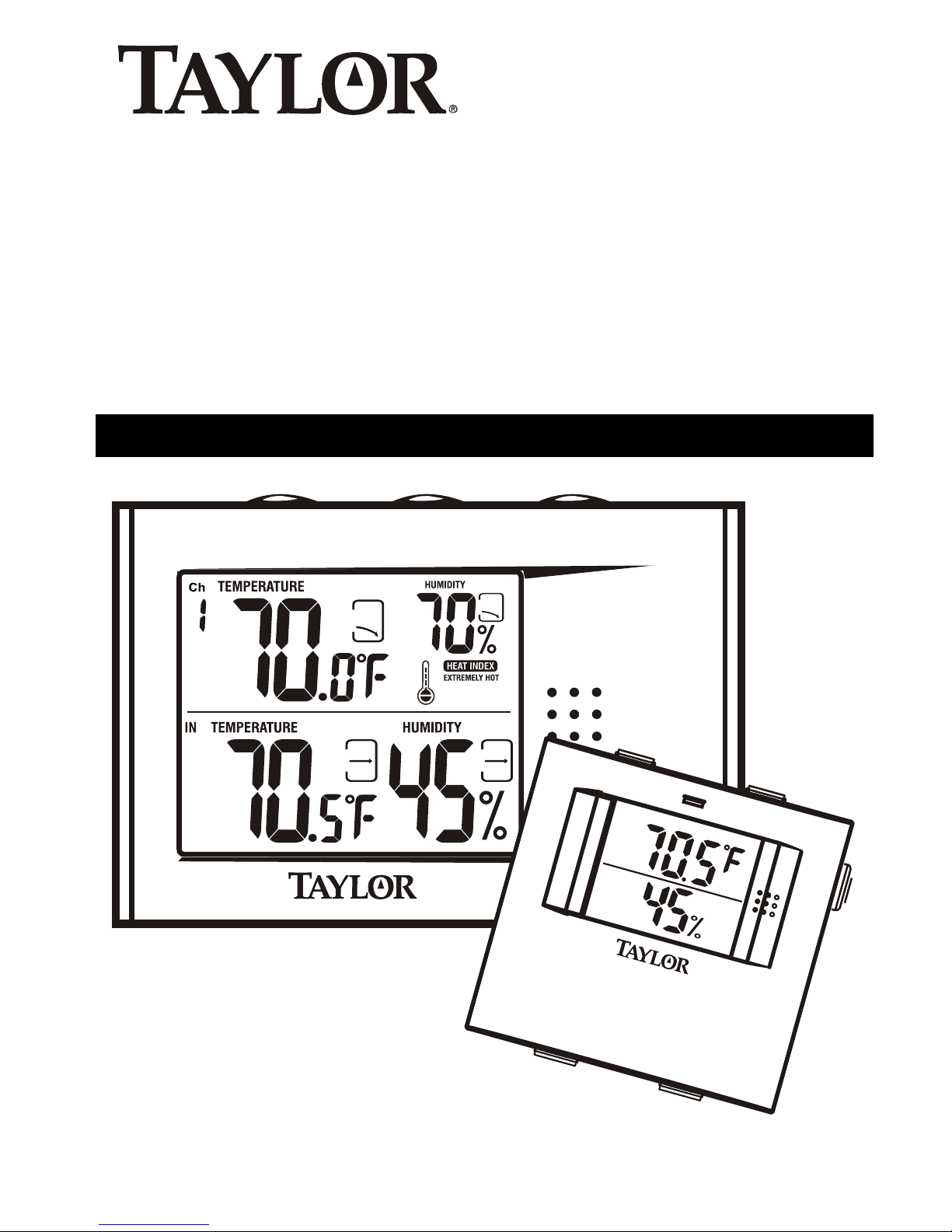
Instruction Manual
Digital Wireless
Weather System
Thermometer, Hygrometer and
Heat Index with Remote Sensor
Leading the Way in Accuracy™
1458
Page 2
Congratulations on your purchase of the Taylor®
Digital Wireless Weather System: Thermometer &
Hygrometer with Remote Sensor. This state-of-the
art measurement instrument is engineered and
designed to meet the highest quality standards…to
assure you uncompromising accuracy and
consistently dependable, convenient performance.
In order to optimize its function, please read this
instruction manual carefully before use…and keep
it handy for future reference.
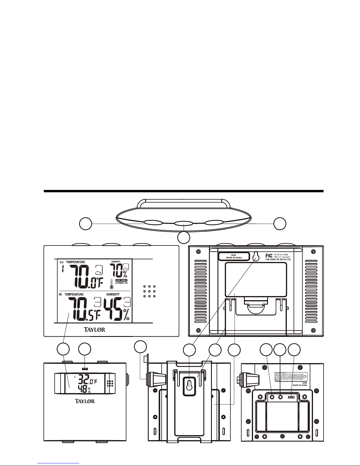
Description of Parts
A
N
H
N
E
C
L
E
O
D
M
R
A
E
L
C
C H
TM
°F/ °C
1 2 3
CHANNEL
1
3
Receiver Unit
Remote Unit
1
2
478
6
5
9
11
12
01
Page 3

2
Main Features & How to Access Functions
1 - LCD Display
Receiver unit displays the temperature, humidity and
heat index readings of up to three remote sensors (with
additional remote unit purchases - see How To Set Up
Your Wireless Thermometer section of this manual) and
indoor temperature and humidity at its location. Temp
Trend / Humidity Trend graphs chart upward, downward
and steady conditions.
Each remote unit displays the indoor or outdoor
temperature, humidity and heat index at its individual
location.
2 - LED Indicator (Remote Unit)
Flashes when remote sensor transmits a reading.
3 - Channel Button (Receiver Unit)
Press to select channel 1, 2, or 3 to display remote
temperature. Hold 3 seconds to delete current channel.
Dashes will replace channel setting. To set a new
channel, slide channel switch on the remote unit. Press
TM button and the selected channel will appear on the
receiver unit display.
4 - Channel Switch (Remote Unit)
Slide to designate the remote sensor channel 1, 2, or 3.
5 - Mode Button Dual Function (Receiver Unit)
1) Max/Min Memory: Press and release to view daily
high temperature for 5 seconds. Press and release again
to view daily low temperature for 5 seconds.
2) F/C Selection: Hold 3 seconds to set temperature
measurement to F° or C° scale.
Page 4

6 - Clear Button (Receiver Unit)
To delete Max/Min Memory record, press while the
respective values are displayed on the readout.
7 - F°/C° Button (Remote Unit)
Press to select F° or C° temperature scale.
Note: Temperature scale selected on receiver unit will
control what is displayed.
8 - TM Button (Remote Unit)
Press to send a transmission signal to receiver unit.
9 - Battery Compartment
The receiver unit and the remote unit each require 2AA
Alkaline batteries (see Battery Installation in How To Set
Up Your Wireless Thermometer section of this manual).
10 - Table Stand
Allows stable placement of units on a flat surface. To
access on both the receiver and remote units, pull
bottom of stand out from housing.
11 - Wall Mount
The receiver features a recessed key hole and the remote
features a detachable holder with a key hole slot to
secure each unit to a wall.
12 - Cable Jack (Remote Unit)
For use with optional, additional remote sensor unit(s) only
sold separately(Model 1459). Plug sensor probe of 11-foot
cable into jack to measure temperature in liquids (aquarium,
swimming pool, hot tub, etc.)
Main Features (continued)
3
Page 5
Ch
IN
TEMPERATURE
MAX
MIN
HUMIDITY
TEMPERATURE
MAX
MIN
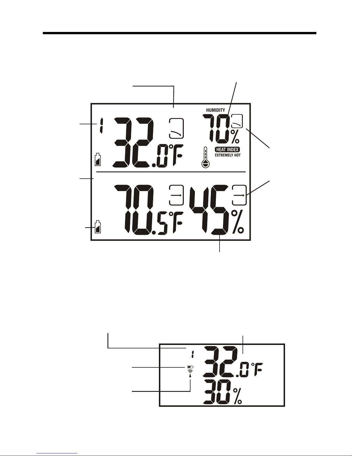
Display Information
(Receiver Unit)
(Remote Unit)
4
Channel
icon
Channel icon
Signal
Transmitting
icon
Low
Battery
indicator icon
Low Battery
indicator icon
Indoor
icon
Max / Min
Memory Mode
icon
Temp Trend/
Humidity
Trend graphs
Current temperature / measurement
scale, humidity and heat index at
remote location of
selected channel
Current temperature / measurement
scale and humidity at remote location
Current temperature / measurement
scale and humidity at receiver
location of selected channel
C H
Page 6

How To Set Up Your Wireless Thermometer
5
• Place the receiver unit as close as possible to
the remote unit. This will ensure easy synchronization between the transmission and reception of
signals as you set up your wireless thermometer.
After set up is completed, position the receiver
unit and remote unit within effective transmission
range which, in usual circumstances, is 100 feet.
Note: The effective range is vastly affected by the
nearby building materials and where the receiver
and remote units are positioned. Try various set ups
for the best results. Shorten the distance between
receiver and remote units when necessary.
Important: Though the remote unit is weather
proof, it should be placed away from direct
sunlight, rain, snow and should never be
submerged in water. Also please note that
below 32ºF / 0ºC the LCD readout on the remote
unit may begin to fail display. When this
happens the remote will still transmit correct
temperature readings to the receiver unit but
can not be viewed at the remote location. When
the temperature rises above 32ºF / 0ºC the
display will begin to function normally again.
Page 7

Battery Installation
6
For the initial installation, insert the
batteries into the receiver unit first,
then the remote unit:
Receiver
1. Lift off the battery compartment cover, located
on the back of the unit.
2. Insert 2 AA alkaline batteries as indicated by
the polarity symbols marked inside the battery
compartment.
3. Replace the battery compartment cover.
'A
A
'
'AA
'
Page 8

Remote
1. Lift off the bracket stand, located on the back
of the unit, to access the battery compartment
cover.
2. Remove the 4 screws that secure the battery
compartment cover and then remove the
cover.
3. Select the Channel setting by sliding the CH
switch to Channel 1 to register the first
sensor, included in this package.
Note: Maximum 3 remote sensor units can be
registered. Should you purchase one or two additional
remote units (Model 1459, sold separately) to expand
your thermometer monitoring capabilities to multiple
locations, slide the CH switch to Channel 2 to register the
second sensor and select Channel 3 to register the third
sensor.
4. Insert 2 AA alkaline batteries as indicated by
the polarity symbols marked inside the
battery compartment.
Battery Installation (continued)
7
°F/°C
1 2 3
CHANNEL
TM
AA'
'
'AA
'
Page 9

Battery Installation (continued)
How to Read Temperatures and Other Displays
8
Important: When the temperature falls below
freezing point, the batteries of outdoor units may
freeze, lowering their voltage supply and effective
range. Use Lithium batteries to insure operation
below 10°F (-12° C).
5. Press the F/C button to select the desired
temperature measurement scale.
6. The remote will automatically send a
transmission to the receiver. The red LED
Indicator light will flash when a signal is
transmitted. Remote unit temperature
updates will then be transmitted at 2 minute
30 second intervals.
Note: If dashes are still displayed on the
receiver unit, press the TM button to send a
transmission.
7. Replace the battery compartment cover,
replace and tighten screws and reattach the
bracket stand.
• The top half of the receiver display will show
the temperature, humidity and heat index of
one remote unit (set to Channel 1). If more
than one remote unit is set, simply press the
Channel button on the receiver unit until it
correlates to the designated channel of the
second /third remote location(s).
Page 10

How to Read Temperatures and Other Displays (continued)
9
•The bottom half of the receiver display will show
indoor temperature and humidity at its location.
•The Temp Trend/Humidity Trend graphs on top &
bottom of the receiver unit display show an Up
symbol when the temperature increases more
than 1 degree (humidity 3%), a Steady symbol
when temperature change is less than 1 degree
(humidity less than 3%), or a Down symbol
when the temperature decreases more than 1
degree (humidity 3%) for 60 minutes in the
remote and receiver locations.
•To view high/low daily temperatures (Max/Min
Memory) press Mode button on the receiver unit
(see Features & How to Access Functions section
of this manual).
•The Heat Index combines temperature and
relative humidity for an “apparent” temperature,
or how hot it actually feels. As the heat index
rises, so do the risks of heat disorders.
Classification
Heat Index
Temp Range
General Effect on
People at High Risk
Extremely
Hot
Very Hot
Hot
Very Warm
130ºF or
Higher
105ºF to
129ºF
90ºF to
104ºF
80ºF to
89ºF
Heat or Sunstroke highly likely
with continued exposure.
Sunstroke, heat cramps, or heat
exhaustion likely, and heatstroke
possible with prolonged exposure
and/or physical activity.
Sunstroke, heat cramps, or heat
exhaustion possible with prolonged
exposure and/or physical activity.
Fatigue possible with prolonged
exposure and/or physical activity.
Page 11

Trouble-Shooting
10
Disconnected Signals
• If the receiver unit does not receive a
transmission from a remote unit channel for 1
hour, the display will show dashes. To correct this
problem:
1. Go to the remote location of that channel to
check that the unit is properly positioned,
within the appropriate transmission range.
2. If new batteries are faulty on the initial
installation, install fresh batteries. If you did
not notice the Low Battery icon warning and
the product performed correctly after initial
set up, the batteries have lost their charge.
Replace batteries (see steps for Battery
Installation in the How To Set Up Your
Wireless Thermometer section of this
manual.)
3. Check to make sure the transmission path is
clear of obstacles and interference.
Battery Replacement (continued)
Note: When replacing batteries in the remote unit,
remember to clear the corresponding channel of
the receiver unit by 1) pushing the channel button
to select the respective channel; 2) holding the
channel button for 3 seconds to clear the
registration.
• When the batteries on the receiver unit or the
remote unit are low, the Low Battery Indicator
icon will light up on the relevant displays.
Follow the steps for Battery Installation in the
How To Set Up Your Wireless Thermometer
section of this manual.
Page 12

Trouble-Shooting (continued)
11
Disconnected Signals (continued)
Note: This equipment has been tested and found
to comply with the limits for a Class B digital
device, pursuant to Part 15 of the FCC Rules.
These limits are designed to provide reasonable
protection against harmful interference in a
residential installation. This equipment
generates, uses and can radiate radio frequency
energy and, if not installed and used in
accordance with the instructions, may cause
harmful interference to radio communications.
However, there is no guarantee that interference
will not occur in a particular installation. If this
equipment does cause harmful interference to
radio or television reception, which can be
determined by turning the equipment off and on,
the user is encouraged to try to correct the
interference by one or more
of the following measures:
--Reorient or relocate the receiving antenna.
--Increase the separation between the equipment
and receiver.
Modifications not authorized by the manufacturer
may void users authority to operate this device.
Page 13

Trouble-Shooting (continued)
12
Transmission Collision
Signals from other household devices, such as doorbells,
home security systems and entry controls, may interfere.
This is normal and does not affect the general
performance of this product. The transmission will resume
once the interference recedes.
Precautions
This Wireless Thermometer & Hygrometer with Remote
Sensor is engineered to give you years of satisfactory
service if you handle it carefully, following these
guidelines:
1. The receiver is intended for indoor use only. It is
not sealed against moisture and could be damaged
if used outdoors.
2. Do not immerse the unit in water. If you spill
liquid on it, dry immediately with a soft, lint-free
cloth.
3. Do not clean the unit with abrasive or corrosive
materials. This may scratch plastic parts and
corrode electronic circuits.
4. Do not subject unit to excessive force, shock, dust,
temperature or humidity. This may result in
malfunction, shorter electronic life span, damaged
battery or distorted parts.
5. Do not tamper with the unit's internal components.
Doing so will invalidate the warranty on this
product and may cause damage. The unit contains
no user-serviceable parts.
6. Do not mix old and new batteries.
7. Always read the instruction manual before
operating this product.
Page 14

Specifications
13
Range of temperature measurement:
Receiver unit (indoor only):
32°F to 122°F (0°C to 50°C)
Remote unit: -4°F to 140°F (-20°C to 60°C)*
Using Sensor Probe Cable:
-58°F to 158ºF (-50°C to 70ºC)**
Humidity Range (1459 Only): 20% to 99% (if
humidity drops below 20% the humidity display
will stay at the last reading until the humidity rises
within the mentioned range)
Transmission: Max. 30M (100 ft.)
open area, RF434 MHz
Resolution: 0.1 degree for temperature
1% for humidity
Battery life: 1 year (alkaline batteries recommended)
Heat Index Classifications
Extremely Hot: 130°F or higher (55°C or higher)
Very Hot: 105°F - 129°F (40°C - 54°C)
Hot: 90°F - 104°F (32°C - 39°C)
Very Warm: 80°F - 89°F (26°C - 31°C)
*Important: To extend outdoor temperature range
to -40°F to 140°F (-40°C to 60°C) use 2 AA Lithium
batteries.
** Using the sensor probe cable will allow you to
keep the unit in a warmer place with out using
Lithium batteries.
Page 15

One Year Warranty
14
This product is warranted against defects in
materials or workmanship for one (1) year from
date of original purchase. It does not cover
damages or wear resulting from accident, misuse,
abuse, commercial use, or unauthorized
adjustment and/or repair.
Should this product require service (or
replacement at our option) while under warranty,
do not return to retailer. Please pack the item
carefully and return it prepaid, along with store
receipt showing date of purchase and a note
explaining reason for return to:
Taylor Precision Products
2220 Entrada Del Sol
Las Cruces, New Mexico 88001
www.taylorusa.com
There are no express warranties except as listed
above. This warranty gives you specific legal rights,
and you may have other rights which vary from
state to state.
Page 16

15
Made to our exact specifications in China.
© 2005 Taylor Precision Group, LLC and its
affiliated companies, all rights reserved. Taylor is
a registered trademark of Taylor Precision
Products Group, LLC and its affiliated companies.
CP1458-7.05
 Loading...