

Page 1

Model C005
Refrigerated Dairy Dispenser
Operating Instructions
067852--M
7/23/09
Page 2

Complete this page for quick reference when service is required:
r
Taylor Distributor:
Address:
Phone:
Fax:
E-mail:
Service:
Parts:
Date of Installation:
Information found on the data label:
Model Number:
Serial Number:
Electrical Specs: Voltage Cycle
Phase
Maximum Fuse Size: A
Minimum Wire Ampacity: A
E July, 2009 Taylo
All rights reserved.
067852-M
Taylor Company
The word Taylor and the Crown design
are registered trademarks in the United States
of America and certain other countries.
a division of Carrier Commercial Refrigeration, Inc.
750 N. Blackhawk Blvd.
Rockton, IL 61072
Page 3

Table of Contents
Section 1 Safety 1....................................................
Section 2 To the Installer 3............................................
Installing the Dairy Dispenser 5...........................................
Section 3 Operator Parts Identification 6...............................
Section 4 Important: To the Operator 7.................................
Power Switch 8.........................................................
Product Level Reset Button 8.............................................
Temperature Adjustment 9...............................................
Product Temperature Indicator 9..........................................
Indicator Lights 9.......................................................
Cappuccino and Latté Selections 10........................................
Clean/Lockout Feature 10.................................................
Product Selection 10.....................................................
Calibration 11...........................................................
Section 5 Operating Procedures 12.....................................
Starting the Dispenser 12.................................................
Set Up Tanks 13.........................................................
Assembly and Start Up 14................................................
Dispensing Product 16....................................................
Recipe Settings 19.......................................................
Model C005 Table of Contents
Page 4

Table of Contents - Page 2
Section 6 Cleaning and Main ten ance 20.................................
Cleaning Procedure 20...................................................
Disassembly/Cleaning 20.................................................
Equipment Cleaning and Maintenance Schedule 22..........................
Section 7 Troubleshooting Guide 23....................................
General Troubleshooting 23...............................................
Section 8 Parts List 25.................................................
Wiring Diagram 28.......................................................
Note: Continuing research results in steady improvements; therefore,information
in this manual is subject to change without notice.
E July, 2009 Taylor
All rights reserved.
067852--M
Taylor Company
The word T aylor and the Crown design
are registered trademarks in the United States
of America and certain other countries.
a division of Carrier Commercial Refrigeration, Inc.
750 N. Blackhawk Blvd.
Rockton, IL 61072
Table of Contents Model C005
Page 5
Section 1 Safety
We at Taylor are concerned about the safety of the operator when he or she comes in
contact with the dispenser and its parts. Taylor has gone to extreme efforts to design and
manufacture built-in safety features to protect both you and the service technician. As an
example, warning labels have been attached to the dispenser to further point out safety
precautions to the operator.
IMPORTANT-F ailu re to adhereto thefo llo wingsafetyprecautions mayresult
in severe personal injury or death. Failure to comply with these warnings may
damage the machine and its components. Component damage will result in part
replacement expense and service repair expense.
To Op erate Safely:
DO NOT operate the dispenser without reading this operator's manual. Failure to
follow this instruction may result in equipment damage, poor dispenser performance,
health hazards, or personal injury.
DO NOT operatethedispenser unless itisproperly grounded. Failure to followthis
instruction may result in electrocution.
Always plug the dispenser into an approved electrical outlet. Do not touch the
dispenser with wet hands. Failure to follow this instruction may result in electrocution.
Do not immerse the dispenser in water. Failure to follow this instruction may result
in electrocution.
Observe the same safety precautions with the dispenser that you would with any
electrical appliance. Failure to follow this instruction may result in electrocution.
Allrepairs mustbe performedbya qualifiedservicetechnicianwiththemain power
supply to the dispenser disconnected. Failure to follow this instruction may result in
electrocution. Contact your local authorized Taylor Distributor for service.
DO NOT operate the dispenser unless all service panels and access doors are
restrainedwithscrews. Failuretofollowthisinstructionmay resultinelectrocution.Contact
your local authorized Taylor Distributor for service.
Model C005 Safety
1
Page 6

This dispensing unit must be placed on a level surface. Use caution when moving
the unit. Failure to comply may cause the unit to tip over, and result in personal injury.
DO NOT obstructairintakeand discharge openings: Minimum of 1” (25.4 mm) at ther ear
and 4” (102 mm) under the unit for adequate air flow across the condenser.
NOISE LEVEL: T his unit meets the airborne noise emission standard according to the
applicable European Directive.
If the crossed out wheeled bin symbol is affixed to this product, it signifies thatthis
product iscompliant with the EUDirectiveas well as other similar legislationin effect after
August13,2005. Therefore, itmust be collectedseparately after itsuse is completed,and
cannot be disposed as unsorted municipal waste.
The user is responsible for returning the product to the appropriate collection facility, as
specified by your local code.
For additional information regarding applicable local laws, please contact the municipal
facility and/or local distributor.
Safety Model C005
2
Page 7
Section 2 To the Installer
Overview
The dairydispenser Model C005dispensesthree productsin different volumesfor coffee,
cappuccino, and latté products. The dispenser issupplied with a cord and grounding type
plug.
Specifications
Capacity: 2 tanks x 1.5 gallons (whole milk, skim milk), 1 tank x 2.5 gallons (cream)
Weight: 95 lbs., Crated Weight: 101 lbs.
Dimensions: 25” D x 12-1/2” W x 27” H
Electrical Requirements
ElectricalRequirements:120V, AC, 15 amp., single phase, 60 mHz, supplied with NEMA
cord and plug 5-15P.
The dispenser includes a micro controller and must be operated on grounded electrical
wiring at all times. A qualified technician must complete any electrical servicing. Servicing
of the dispenser by unauthorized personnel makes the warranty null and void.
It is recommended that this dispenser be plugged into an electrical surge protector,
selected by a qualified service technician, for added protection against power surges,
which could damage an electrical/electronics component. An electrical surge event may
cause the unit to shut down. Such an event would require service by a qualified service
technician if the dispenser was not adequately protected.
In the United States, this equipment is intended to be installed in accordance with the
National Electrical Code (NEC), ANSI/NFPA 70-1987. In all other areas of the world,
equipment shouldbe installed in accordancewiththe existing localcodes.Pleasecontact
your local authorities. The purpose of the NEC code is the practical safeguarding of
persons and property from hazards arising from the use of electricity. This code contains
provisions considered necessary for safety. Compliance therewith and proper
maintenance will result in an installation essentially free from hazard!
FOLLOW YOUR LOCAL ELECTRICAL CODES!
CAUTION:THIS EQUIPMENTMUSTBE PROPERLYGROUNDED!FAILURETO
DO SO CAN RESULT IN SEVERE PERSONAL INJURY FROM ELECTRICAL SHOCK!
Model C005 To the Installer
3
Page 8

Air Clearance
Always allow a minimum of 1” (25.4 mm) at the rear and 4” (102 mm) under the unit for
adequate air flow across the condenser.
Refrigeration Servicing
The temperature is set at the factory to maintain the product within the range of 35_Fto
41_F(1.7_Cto5.0_C).
Warranty
One year on parts and labor, excluding wear items.
CAUTION: Warranty is valid only if required service work is provided by an Authorized
Taylor Service Technician.
Note: Taylor reserves the right to deny warranty claims on equipment or parts if a
non-approved refrigerant was installed in the machine, system m odifications were
performed beyond factory recommendations, or it is determined that the failure was
caused by neglect or abuse.
Compressor Warranty Disclaimer
The refrigeration compressor on this machine is warranted for one year. However, dueto
the Montreal Protocol and the U.S. Clean Air Act Amendments of 1990, many new
refrigerants are being tested and developed, thus seeking their way into the service
industry.Some ofthese newrefrigerantsare beingadvertised asdrop-in replacementsfor
numerous applications. It should be noted that, in the event of ordinary service to this
machine'srefrigerationsystem, onlythe refrigerantspecified onthe affixeddata plate
shouldbe used.The unauthorized useof alternate refrigerantswill voidyourcompressor
warranty. It will be the owner's responsibility to make this fact known to any technician he
employs.
It should also be noted that Taylor does not warrant the refrigerant used in its equipment.
For example,ifthe refrigerant islostduring the course ofordinaryservice to thismachine,
Taylor has no obligation to either supply or provide its replacement either at billable or
unbillable terms.
Taylor will continue to monitor the industry and test new alternates as they are being
developed. Should a new alternate prove, through our testing, that it would be accepted
as a drop-in replacement, then the above disclaimer would become null and void. To find
out thecurrentstatus of an alternaterefrigerant as it relates toyour compressor warranty,
call the local Taylor Distributor. Be prepared to provide the Model/Serial Number of the
freezer in question.
To the Installer Model C005
4
Page 9
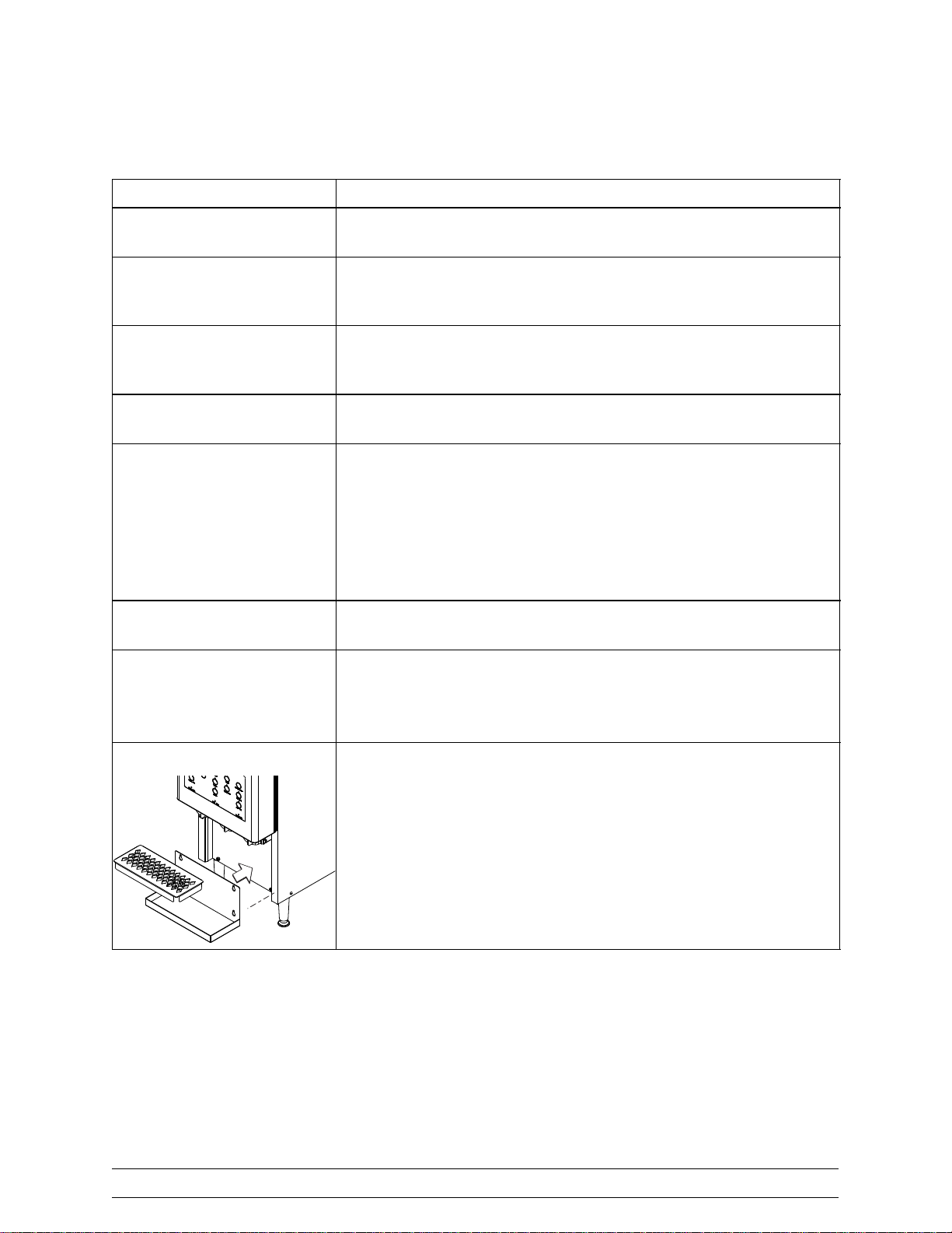
Installing the Dairy Dispenser
Step Action
1 Place the dairy dispenser where it will best serve your
operation.
2 Make sure that counters, platforms, and shelves are strong
enough to support the weight of the dispenser and full
containers of product ( 139 lbs. [63 kg.]).
3 Maintain a minimum of 1” (25.4 mm) at the rear and 4”
(102 mm) under the unit for adequate air flow across the
condenser.
4 Place the dispenser at a convenient height for the operator
to access the keys and cups.
5 DO NOT remove the legs from the dispenser or allow
the dispenser to sit directly on the counter.
Adequate air flow under the machine is necessary for
proper operation.
Make sure the legs at the four corners of the dispenser are
firmly attached.
Removal of the legs violates the warranty.
6 Make sure the unit is level. (Adjust the legs to ensure the
dispenser is level and does not rock on the counter.)
7 Plug the power cord into the proper electrical outlet (NEMA
5-15P).
Allow the unit to run for twenty minutes prior to filling
with product.
8 Install the drip tray and the splash shield.
Model C005 To the Installer
5
Page 10
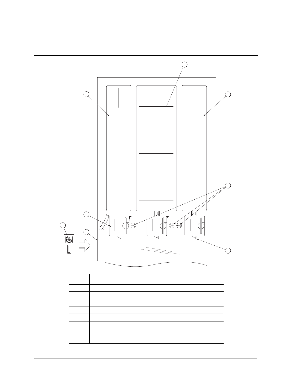
Section 3 Operator Parts Identification
0
B
A
C
5
3
FULL
3
FULLFULL
4
CREAMWHOLE MILK SKIM MILK
2
3
2
2
1
1
F
1
D
H
G
E
ITEM DESCRIPTION
A PRODUCT TANK 1-1/2 GAL (WHOLE MILK)
B PRODUCT TANK 2-1/2 GAL (CREAM)
C PRODUCT TANK 1-1/2 GAL (SKIM MILK)
D PRODUCT DISPENSING VALVE DOOR
E DISPENSING TUBE
F RESET BUTTONS
G POWER SWITCH
H TEMPERATURE ADJUSTMENT (± 2 DEGREES)
Operator Parts Identification Model C005
6
Page 11

Section 4 Important: To the Operator
ITEM DESCRIPTION
1 EXTRA PORTIONKEY (1/2 OZ.)
2 PORTION SIZE KEYS
3 1ST RECIPE MODIFIER SELECT KEY
4 1ST RECIPE MODIFIER SELECT INDICATOR
5 2ND RECIPE MODIFIER SELECT KEY
6 2ND RECIPE MODIFIER SELECT INDICATOR
7 3RD RECIPE MODIFIER (LATTÉ) SELECT KEY
8 3RD RECIPE MODIFIER (LATTÉ) SELECT INDICATOR
9 4TH RECIPE MODIFIER (CAPPUCCINO) SELECT KEY
10 4TH RECIPE MODIFIER (CAPPUCCINO) SELECT INDICATOR
11 5TH RECIPE MODIFIER SELECT KEY
12 5TH RECIPE MODIFIER SELECT INDICATOR
13 PRODUCT SELECT KEYS
14 PRODUCT SELECT/MIX LOW INDICATORS
15 PRODUCT CONTAINER “CLEAN” INDICATORS
16 POWER INDICATOR
17 PRODUCT LEVEL INDICATOR
18 PRODUCT TEMPERATURE INDICATOR
Model C005 Important: To the Operator
7
Page 12

Power Switch
The power switch is located on the left side of the unit. When the unit is plugged into a
receptacle and the power switch is placed in the ON position, the powerindicator light will
illuminate. The cabinet will start cooling and the control is powered up. The power switch
is left in the ON position during normal operations.
Product Level Reset Button
Eachproduct tank hasaseparate resetbutton.The reset buttonsarelocated next toeach
product dispensing valve door. These buttons are used to reset the control when a
particulartank isrefilled, andtoinstructthecontrolof thelevel ofmix inthe particulartank.
Each tank can b e refilled, reset and cleaned independently of each other.
The product tanks must be filled to the half gallon increments indicated on the tanks. The
operator hasthree product level optionswhen filling theWHOLEand SKIMmilk tanks: 1/2
gallon, 1 gallon, or 1-1/2 gallons. The operator has five product level options when filling
the CREAM tank: 1/2 gallon, 1 gallon, 1-1/2 gallons, 2 gallons, and 2-1/2 gallons.
When each product tank is refilled, the operator must press the corresponding product
level reset button to match the fill level. The product level selected is displayed on the
productlevelindicatoronthefrontpaneldisplay.Theindicatorcorresponds tothe filllevels
as noted below.
WHOLE and SKIM Milk
Product Tank Levels
Level 3 = 1-1/2 Gallons
Level 2 = 1 Gallon
Level 1 = 1/2 Gallon
IMPORTANT: The operator must ensure that the level of product/dairy in the tank
corresponds to the number shown on the product level indicator. FAILURE TO
FOLLOW THIS INSTRUCTION WILL RESULT IN INCORRECT PORTIONING!
Theproductlevel indicator hasan automatic time-out feature.Theindicator display willgo
blank if approximately 6 seconds pass between presses of the reset button. The product
level indicator automatically starts the level sequence over again if the reset button is
pressed two more times after the lowest number has been reached.
Note: Don't press the reset button unless the tank has been refilled or the tank has been
cleaned.
Product Tank Levels
Level 5 = 2-1/2 Gallons
Level 4 = 2 Gallons
Level 3 = 1-1/2 Gallons
Level 2 = 1 Gallon
Level 1 = 1/2 Gallon
CREAM
Important: To the Operator Model C005
8
Page 13

Temperature Adjustment
The temperature is set at the factory to maintain the product within the range of 35_Fto
41_F(1.7_Cto5.0_C). The oper ator has the capability to make a slight adjustment (± 2_)
to the cabinet temperature. (Note: The product temperature must NOT exceed
41_F / 5.0_C). The temperature adjustment screw is located above the power switch.
Before a temperature adjustment is made, make sure the product temperature has been
tested several times throughout the day (24 hour minimum).
Product Temperature Indicator
The product temperature indicator displays the product temperature.
(IMPORTANT: Allow the unit to operate for three or more hours before comparing the
product temperature to the display.)
Indicator Lights
Power
This light will illuminate when power is supplied to the unit, and the power switch is in the
“ON” position.
3rd Recipe Modifier Key (from left side) - Latté
This light will illuminate when a Latté drink is selected.
4th Recipe Modifier Key (from left side) - Cappuccino
This light will illuminate when a Cappuccino drink is selected.
5th Recipe Modifier Key (from left side)
This light will illuminate when a drink is selected.
Whole Milk
This light will illuminate when whole milk is selected.
Cream
This light will illuminate when cream is selected.
Skim Milk
This light will illuminate when skim milk is selected.
Product Low Level
Eachproduct lightalso servesas theproduct “LOW”light.Whenthecontrol sensesa“low”
condition (approximately 30 oz. until empty) for a particular product, the corresponding
light will flash.
Model C005 Important: To the Operator
9
Page 14

Product Out Level
Eachproductlightalso servesastheproduct “OUT”light.Whenthe controlsensesan“out”
conditionfor aparticular product,thecor respondinglight willilluminate andproduct willnot
dispense.
Clean
Each product container has its own “CLEAN” indicator light. Each product container has
to be removed for cleaning at least every 72 hours. Otherwise, that particular product will
lockout and not dispense product.
Cappuccino and Latté Selections
These are the 3rd and 4th recipe modifier keys, located in the center row of the display.
Note: The Cream product is not an option with these two beverages.
Clean/Lockout Feature
To assure that NSF food safety standards are adhered to, a 72 hour lockout feature is
provided. To minimize the amount of product discarded in this process, the following two
features have been added:
1. The “CLEAN” light associated with each product tank will begin to flash 68 hours
after the last cleaning (four hours prior to the lockout).
2. Each product tank will have its own lockout interval. This allows cleaning of
individual product tanks.
To reset the 72 hour lockout feature:
S Place the power switch in the ON position.
S Open the dispensing door.
S Discard the remaining product.
S Clean the tank, lid, and funnel.
S Install a new product tube.
Product Selection
Recipe Base Select
Thebase selectionforthe 5threcipemodifierkeyisactivatedbya mountedswitch,located
inside the lower front of the unit.
Toggle Switch Position: UP = Coffee Base (Default):
- Small = 4 oz., Medium = 6 oz., Large = 8 oz.,
Toggle Switch Position: DOWN = Neutral Base:
- Small = 3 oz., Medium = 4.5 oz., Large = 6 oz.
When the unit leaves the factory, the base selected is the coffee base (toggle switch is in
the UP position). This is indicated by the green indicator light which illuminates when the
5th recipe modifier key is selected.
Important: To the Operator Model C005
10
Page 15

To change to the neutral base, perform the following steps:
1. Place the power switch in the OFF position.
2. Unplug the unit from the wall receptacle.
3. Remove the lower front control panel.
4. Flip the toggle switch to the DOWN position.
5. Install the lower front control panel.
6. Plug the unit into the wall receptacle.
7. Place the power switch in the ON position.
The unit is now set for the neutral base product. This state is indicated by the amber
indicator light which illuminates when the 5th recipe modifier key is selected.
Calibration
Tools Needed: scale (grams and/or ounces) and small coffee cups
IMPORTANT: Calib ration is by weight, not volume.
Before starting calibration, the dispenser should be sanitized and NEW tubes installed,
prior toaddingthe product. The dispensermusthave the product(s) to be calibrated reset
totheir highestfilllevels.The dispensermust notbeinamixlow, mixout,lock outwarning,
or lock out condition.
1. Place the power switch in the ON position.
2. Press and hold the EXTRA key for approximately 4 seconds. The letters “CA” will
be displayed for 5 seconds. This indicates that the machine is in the Calibration
mode. When the “CA" disappears, the calibration process can begin.
3. Place a small coffee cup under the spout to be calibrated.
4. Select the product (beverage type, if applicable) and the size to be calibrated.
The p roduct or beverage indicator will illuminate.
5. Press the WHOLE MILK reset button.
6. Measure the amount dispensed (+/- 10%) compared to the recipe.
Note: Ifcalibrationis required,presstheSKIMreset buttonto increasethe amount.Press
theCREAMreset buttonto decreasetheamount. Thedisplaywill increment ordecrement
with each button press. Each press of the button counts as approximately 2 grams.
7. If adjustments were made, place the small coffee cup under the spout and press
the WHOLE MILK reset button.
8. Measure the amount dispensed.
9. Press and hold the EXTRA key for approximately 5 seconds and release. The
letters “DN” (done) will appear on the display for approximately 5 seconds.
10. The display will go blank and the unit is r eturned to normal operation.
Model C005 Important: To the Operator
11
Page 16

Section 5 Operating Procedures
We begin our instructions at the point where the parts are disassembled and laid out.
The following steps will explain how to clean, sanitize, assemble and install the
components for the product dispenser.
If youaredisassembling the unitforthe first time or need informationto getto this starting
point in our instructions, turn to page 20, “Disassembly” and start there.
Starting the Dispenser
Step Action
1 Make sure the unit is plugged into a receptacle. Place the
power switch in the “ON” position.
2 The machine is powered when plugged into a receptacle
and the power indicator light is illuminated.
3 Allow the machine to refrigerate for 20 minutes before
loading product. The unit must maintain the compartment
temperature between 35_Fto41_F(1.6_Cto5.0_C).
Operating Procedures Model C005
12
Page 17

Set Up Tanks
Step Action
1 Prepare the 3 compartment sink with an approved 100
2 Thoroughly wash, rinse, sanitize and air dry all tanks, lids,
3 Install the dispensing tubes onto the product tank's
PPM cleaning/sanitizing solution (example: Kay-5r). USE
WARM WATER AND FOLLOW THE MANUFACTURER'S
SPECIFICATIONS.
and funnels.
adaptors/spouts.
Model C005 Operating Procedures
13
Page 18

Assembly and Start Up
Step Action
1 With the compartment door open, open the product
2 With sanitized hands and/or clean gloves on, install the
dispensing valve doors.
product tank, tank covers, tank funnels and dispensing
tubes. (Be sure the tanks are placed in their appropriate
locations.)
3 Close the product dispensing valve doors onto the
dispensing tubes.
Push and turn the key clockwise to “Close/Lock” the
dispensing valve door in place.
4 Close the compartment door.
Operating Procedures Model C005
14
Page 19

Assembly and Start Up (Continued)
Step Action
5 Install the drip tray and the splash shield.
6 Fill each product tank through the lid/funnel with the
appropriate product and proper amount.
7 Label each tank with a 72 hour shelf life.
8 Push the reset button the appropriate number of times to
indicate the fill level for each product. The product indicator
light will stay illuminated for 6 seconds.
The reset display indicator will indicate the number of 1/2
gallons selected in each tank. (Example: Level 5 = 2-1/2
gallons, Level 4 = 2 gallons, Level 3 = 1-1/2 gallons,
Level 2 = 1 gallon, Level 1 = 1/2 gallon.)
Model C005 Operating Procedures
15
Page 20

Dispensing Product
Theproductand volumeto bedispensed areselected bypressingthekeysontheselector
keypad on the compartment door.
To dispense product, follow these steps:
Step Action
1 Place a cup under the appropriate dispensing tube and
press the product key (Whole Milk, Cream or Skim Milk) to
be dispensed.
2 Select the type of beverage. If no selection is made, the
unit will default to “Hot or Iced Coffee” recipes.
Operating Procedures Model C005
16
Page 21

Step Action
3 Press the portion size key to be dispensed (S, M, L, or XL).
(Note: XL is not a valid selection for the 5th recipe modifier
key.)
4 Remove the cup.
Model C005 Operating Procedures
17
Page 22

If additional product is desired, follow these steps:
Step Action
1 Press the product key (Whole Milk, Cream or Skim Milk).
2 Press the “Extra” key.
1/2 oz. of product selected will be dispensed.
Operating Procedures Model C005
18
Page 23

Recipe Settings
Recipe Modifier Key Extra Small Medium Large Extra
Large
None (Defaults to Coffee) 0.5 1 1.5 2 2.5
1(Future)
2(Future)
3 (Whole or Skim, No Cream) 0.5 6 9 12 14
4 (Whole or Skim, No Cream) 0.5 4 6 8 10
5 (Toggle Switch Up) 2 4 6 8
5 (Toggle Switch Down) 2 3 4.5 6
Note: The recipe modifier keys are the unlabeled keys located in the center row of the
display. The modifier keys 1 - 5 are counted from left to right.
Model C005 Operating Procedures
19
Page 24

Section 6 Cleaning and Maintenance
Cleaning Procedure
ALWAYS FOLLOW LOCAL HEALTH CODES!
To disassemble and clean the unit, the following items will be needed:
S Brushes (provided) - 1 tank brush, 1 tank spout brush, 1 valve brush
S Cleaner/Sanitizer (example: Kay-5r)
S Sanitizer spray bottle (provided)
S Single service hand towels
Disassembly/Cleaning
Step Action
1
2 Open the compartment door.
3 Open the product dispensing valve door. Allow the product
to empty into a container and discard the remaining
product.
4 Repeat Step 3 for the remaining two product tanks.
5 Take the product tanks, product tank covers, tank funnels,
and the drip tray (if applicable) to the 3 compartment sink
for cleaning.
PLACE THE POWER SWITCH IN THE
“OFF” POSITION. Failure to follow this
instruction may result in electrocution.
Cleaning and Maintenance Model C005
20
Page 25

Disassembly (Continued)
Step Action
6 Prepare the 3 compartment sink with an approved 100
7 Remove the dispensing tubes from the product tanks, and
8 Thoroughly brush clean all disassembled parts. Make sure
9 Rinse and place all parts in the cleaning/sanitizing solution
PPM cleaning/sanitizing solution (example: Kay-5r). USE
WARM WATER AND FOLLOW THE MANUFACTURER'S
SPECIFICATIONS.
discard. (Note: dispensing tubes must be discarded at
least every 72 hours.)
all product film is removed.
for one minute.
10 Place all cleaned parts on a clean, dry surface to air dry.
11 With an approved cleaning/sanitizing solution in the
sanitizer spray bottle and a small valve brush, thoroughly
spray and brush clean the plunger spout area and the
product dispensing valve door.
12 With a single service hand towel, wipe down the interior
and exterior of the dispenser.
Model C005 Cleaning and Maintenance
21
Page 26

Equipment Cleaning and Maintenance Schedule
Frequency Equipment Procedure
Every 4 hours Dairy Verify that the product temperatures are
between 35_Fto41_F(1.7_Cto5.0_C).
Every four hours, dispense a small amount
(approx. 2 oz.) of dairy product into a coffee
cup and check the temperature with an
approved Atkins thermometer. Repeat the
process for all three dairy products (whole
milk, cream and skim milk).
Every 24 hours Exterior of
machine
Wipe down the exterior of the machine.
IMPORTANT: Due to the function of the
control, always wipe the d isp lay panel from
top to bottom.
Every 72 hours Tank Wash, rinse, sanitize, and air dry all tanks, lids
and funnels.
Discard used dispensing tubes. Never
reuse dispensing tubes.
Keep a supply of dispensing tubes on hand.
Every 72 hours Plunger spout
area and
product
dispensing
valve door
With an approved cleaning/sanitizing solution
in the sanitizer spray bottle and a small valve
brush, thoroughly spray and brush clean the
plunger spout area and the product
dispensing valve door.
Every 72 hours All Dairy All products in the tank have a maximum shelf
life of 72 hours.
When cleaning the product tanks, discard
the used dispensing tubes and all
remaining dairy product in the tanks.
Every 72 hours Dispensing
Replace all used tubes every 72 hours.
tubes
Every 72 hours Refrigerated
product
compartment
Use a sanitized single service hand towel to
wipe the inside of the product compartment
until all condensation is removed and the
compartment is clean.
Cleaning and Maintenance Model C005
22
Page 27

Section 7 Troubleshooting Guide
General Troubleshooting
Problem Probable Cause Remedy
1. Dispenser will not
operate.
2. Dispenser will not
refrigerate.
3. Dispenser will not
dispense product.
a. Unit is not plugged in. a. Plug unit into
receptacle.
b. Power switch is in the
OFF position.
a. Unit is not plugged in. a. Plug unit into
b. Power switch is in the
OFF position.
a. No product is in the
unit.
b. The dispensing tube is
obstructed or kinked.
c. 72 hour lockout. c. Clean the unit, per
b. Place the power switch
in the ON position. The
power indicator light will
illuminate.
receptacle.
b. Place the power switch
in the ON position. The
power indicator light will
illuminate.
a. Add product to the unit.
b. Clear the obstruction or
kink.
instructions.
4. Frost builds up on the
inside of the cabinet.
5. Improper amount of
product is being
dispensed.
Model C005 Troubleshooting Guide
a. Door is open too often. a. Adjust fill levels
properly.
b. Door gasket is not
sealing.
a. The wrong product was
placed in the tank.
b. Check product
temperature.
23
b. Call service technician.
a. Make sure the
appropriate product is in
the tank.
b. Product added to the
dispenser must be
below 41°F (5.0°C).
Page 28

General Troubleshooting (Continued)
Problem Probable Cause Remedy
5. Improper amount of
product is being
c. Unit was reset
improperly.
dispensed. (Cont'd.)
d. Dispensing tube is not
centered in spout.
e. Dispensing tube is
restricted.
6. Actuator valve is sticky. a. Product is on the
actuator valve solenoid.
b. Faulty actuator valve
solenoid.
7. Product temperature is
too warm.
a. Compartment door is
open too often.
b. Warm product was
placed in the dispenser.
c. Add product and reset
the unit properly.
d. Align the tube properly
or replace the tube.
e. Clear dispensing tube
of restriction.
a. Clean the valve area
with cleaning/sanitizing
solution and a brush.
b. Call service technician.
a. Adjust fill levels properly
so tanks do not need
frequent re filling.
b. Product added to the
dispenser must be
below 41°F (5.0°C).
c. Compartment door
c. Call service technician.
gasket is not sealing.
d. Cabinet temperature is
d. Call service technician.
set too warm.
8. Dispenser is leaking
product.
9. Dispensing door will not
latch.
a. Dispensing tube is not
centered in spout.
b. The valve door was not
shut properly.
a. Dispensing tube is not
centered in spout.
a. Align the tube properly
or replace the tube.
b. Make sur e the valve
door is shut properly.
a. Align the tube properly
or replace the tube.
Note: Note:If theabovesuggestions don'tresolve the problem,pleasecontact yourlocal
Taylor Service Company.
Troubleshooting Guide Model C005
24
Page 29

Section 8 Parts List
UPDATE
REMARKS PARTS
CLASS
QTY. WARR.
NUMBER
DESCRIPTION PART
FASTENER A. *C005* 1/4 TURN X57070 3 103
HARNESS-WIRE *C005* LO VOLT #1 057350 1 103
HINGE-DOOR-DISPENSING *C005* 055877 3 103
RETAINER-PUSH ON *C005* 056797 3 103
SCREW-10-32X1/2FLAT HD-SS 043074 3 000
ACTUATOR-24 VOLT-1/4-20 *C005* 056511-03 3 103 SOLENOID
+ MARKER-WIRE #1 018520 1 000
+ MARKER-WIRE #2 018521 1 000
+ MARKER-WIRE #3 018522 1 000
+ PLUNGER-ACTUATOR-DISPENSER 055889 3 103
+ SPACER-5/16-18 UNC *C005* 057845 3 000
+ SPRING-COMP.ACTUATOR *C005* 055888 3 000
BLOCK A.-DISPENSING *C005* X56502 1 103
BOTTLE-WASH-PLASTIC 044818 1 000
BRUSHWITHRING 058643 1 000
BRUSH-SET CREAMER 058642 1 000
COMPRESSOR PL50F 055613-12 1 103
+ CAPACITOR-START 80UF/220V 055953 1 103
+ RELAY-START-COMPRESSOR-PL50F 055954 1 103
CONDENSER-AC 9X8 -2 ROW 029797 1 103
CORD-POWER-125V-15A-95”L-SO 042936-12 1 103
COVER-MIX TANK-NARROW *C005* 058078 2 103 K3051747/UP
COVER-MIX TANK-WIDE *C005* 058079 1 103 K3051747/UP
DEFLECTOR-AIR/WATER-BASEPAN 056540 1 103
DIAGRAM-WIRING *C005* 056850-12 1 000
DOOR A.-CREAMER *C005* X55892 1 103 K2048437/UP
+ GASKET-DOOR-FOAM C005 R70023 1.5' 000 REPLACES 057841
+ HINGE-CABINETDOOR *C005* 056447 2 103
DOOR A.-CAPTIVE SCREW *C005* X55879 3 103
+ Available Separately
Model C005 Parts List
25
SWITCH-PUSHBUTTON-SPST MOM 056702 3 103
DRYER-CAP. TUBE .021 ID X 9FT 055522 1 000
FAN-EVAPORATOR 3000RPM 105CFM 028534-12 1 103
Page 30

UPDATE
REMARKSWARR.
CLASS
QTY.PART
NUMBER
DESCRIPTION PARTS
FILTER-CORCOM 6EH1 040140-001 1 103
FUNNEL-MIX TANK-NARROW *C005* 058080 2 103 K3051747/UP
FUNNEL-MIX TANK-WIDE *C005* 058081 1 103 K3051747/UP
HARNESS-COFFEE-COOLATTA LOVOLT 058484 1 103 J6 TO LOCKOUT
HARNESS-WIRE *C005* HI VOLT 057349 1 103 J2 TO RESETS
+ Available Separately
HARNESS-WIRE *C005* LO VOLT #2 057351 1 103 J5 Control board to Actuator Solenoids/Relay
HOOK-MAGNETIC 058644 1 103 XXX
INDICATOR-DIGITAL TEMP-SOLAR 056615 1 103 DOOR
+ SCREW-6X1/2 TYPE A-SS-TRUSS HD 022427 2 000
LABEL-OPERATION 065669 1 000
LABEL-INST-FILLDAIRY 065670 1 000
LEG-4” 3/8-16 STUD 036397 4 103
OVERLAY-CONTROL 065629 1 000
PANEL-FRONT-CONTROL *C005* 055914 1 103 UPPER
PANEL-FRONT-CONTROL-CREAMER 056531 1 103 LOWER
PANEL-REAR *C005* 055915 1 103
PCB A.-CONTROL *C005* CREAMER X57838-SER 1 103 K3025267/UP
CHIP-SOFTWARE *C005* CREAMER X40822 1 103
PCB A.-CONTROL-CREAMER X57839-SER 1 103
POTENTIOMETER A. *C005* X57071 1 103 FINE TEMP CONTROL ADJUSTMENT
RELAY-DPDT-24VDC-25A@208/308V 054703-05 1 103 FAN MOTOR & COMPRESSOR
SANITIZER KAY-5 125 PACKETS 041082 1 000
SHIELD-SPLASH *C005* 055920 1 103
SWITCH-ROCKER *370*POWER/LIGHT 048093 1 103
TANK-MIX-1.5 GAL *C005* 057969 2 103 K3051747/UP
TANK-MIX-2.5 GAL *C005* 057968 1 103 K3051747/UP
TRANS.-100VA 120/208/240 PRI 079800 1 103
TRAY-DRIP-SS *C005* 055919 1 103
+ SCREW-SHOULDER 10-32X3/8X.078 057386 2 000
TUBE-DISPENSING *C005* 056579 1 000
VALVE-ACCESS-1/4 MFLX1/4 S-90 047016 1 103
Parts List Model C005
26
Page 31

UPDATE
REMARKSWARR.
CLASS
QTY.PART
NUMBER
DESCRIPTION PARTS
+ CAPACITOR-START 60UF-220/275V 047703 1 103
COMPRESSOR PL35G 055187-27 1 512 220-240V 50HZ 1PH
+ RELAY-START-COMPRESSOR-PL35G 055358 1 103
220-240V 50 HZ 1PH
+ Available Separately
DIAGRAM-WIRING *C005* 056850-40 1 000 220-240V 50HZ 1PH
KIT A.-MOTOR-FAN X62253-27 1 103 220-240V 50HZ 1PH
INSTRUCTION-WEEEEND OF LIFE 064371-INS
Model C005 Parts List
27
Page 32

Model C005
056850--12
Rev . 7/09
 Loading...