

Page 1

OPERATOR’S
MANUAL
Model C001 & C002
Custard Freezers
Original Operating Instructions
055073 - M 5/28/08 (Original Publication)
(Updated 9/22/14)
Page 2

Complete this page for quick reference when service is required:
Taylor Distributor:
Address:
Phone:
Fax:
E-mail:
Service:
Parts:
Date of Installation:
Information found on the data label:
Model Number:
Serial Number:
Electrical Specs: Voltage Cycle
Phase
Maximum F use Size: A
Minimum Wire Ampacity: A
E 2008 Carrier Commercial Refrigeration, Inc.
055073-M
Any unauthorized reproduction, disclosure, or distribution of copies by any person of any portion of this work
may be a violation of Copyright Law of the United States of America and other countries, could result in the
awarding of Statutory Damages of up to $250,000 (17 USC 504) for infringement, and may result in further
civil and criminal penalties.
All rights reserved.
Taylor Company
a division of Carrier Commercial Refrigeration, Inc.
750 N. Blackhawk Blvd.
Rockton, IL 61072
Page 3

Table of Contents
Section 1 To th e Installer 1............................................
Installer Safety 1........................................................
Site Preparation 1.......................................................
Air Cooled Units 1.......................................................
Water Connections (Water Cooled Units Only) 2............................
Electrical Connections 2.................................................
Dasher (Beater) Rotation 3...............................................
Refrigerant 3...........................................................
Section 2 To the Operator 4...........................................
Section 3 Safety 5....................................................
Section 4 Operator Parts Identification 8...............................
C001 Exploded View 8..................................................
C002 Exploded View 10..................................................
Dasher (Beater) and Door Assembly 12.....................................
Accessories 13..........................................................
Section 5 Important: To the Operator 14.................................
C001 14................................................................
C002 15................................................................
Symbol Definitions 16....................................................
Section 6 Operating Procedures 17.....................................
Assembly 17............................................................
Sanitizing 20............................................................
Priming for Continuous Run 21............................................
Stopping a Continuous Run for a Short Period of Time 22.....................
To Restart the Continuous Run: 22.........................................
Closing Procedure 22....................................................
Draining Product From The Freezing Cylinder 23............................
Rinsing 23..............................................................
Cleaning 24.............................................................
Table of Contents Models C001 & C002
Page 4

Table of Contents - Page 2
Disassembly 24..........................................................
Brush Cleaning 24.......................................................
Section 7 Important: Operator Checklist 26..............................
During Cleaning and Sanitizing 26.........................................
Troubleshooting Bacterial Count 26........................................
Regular Maintenance Checks 26...........................................
Winter Storage 27........................................................
Section 8 Troubleshooting Guide 28....................................
Section 9 Parts Replacement Schedule 31...............................
Section 10 Limited Warranty on Equipment 32............................
Section 11 Limited Warranty on Parts 34.................................
Wiring Diagrams 37......................................................
Note: Continuing research results in steady improvements; therefore, information
in this manual is subject to change without notice.
Note: Only instructions originating from the factory or its authorized translation
representative(s) are considered to be the original set of in structions.
E 2008 Carrier Commercial Refrigeration, Inc. (Original Publication)
(Updated September, 2014)
055073- M
Any unauthorized reproduction, disclosure, or distribution of copies by any person of any portion of this work
may be a violation of Copyright Law of the United States of America and other countries, could result in the
awarding of Statutory Damages of up to $250,000 (17 USC 504) for infringement, and may result in further
civil and criminal penalties.
All rights reserved.
Taylor Company
a division of Carrier Commercial Refrigeration, Inc.
750 N. Blackhawk Blvd.
Rockton, IL 61072
Table of Contents Models C001 & C002
Page 5
Section 1 To the Installer
The following information has been included in the
manual as safety and regulatory guidelines. For
complete installation instructions, please see the
Installation Checklist.
Installer Safety
In all areas of the world, equipment should be
installed in accordance with existing local codes.
Please contact your local authorities if you have any
questions.
Care should be taken to ensure that all basic safety
practices are followed during the installation and
servicing activities related to the installation and
service of Taylor equipment.
S Only authorized Taylor service personnel
should perform installation and repairs on the
equipment.
S Authorized service personnel should consult
OSHA Standard 29CFRI910.147 or the
applicable code of the local area for the
industry standards on lockout/tagout
procedures before beginning any installation
or repairs.
S Authorized service personnel must ensure
that the proper PPE is available and worn
when required during installation and service.
S Authorized service personnel must remove all
metal jewelry, rings, and watches before
working on electrical equipment.
Site Preparation
Review the area where the unit will be installed before
uncrating the unit. Make sure all possible hazards to
the user or equipment have been addressed.
For Indoor UseOnly: This unit is designed to operate
indoors, under normal ambient temperatures of
70_-75_F(21_-24_C). The freezer has successfully
performed in high ambient temperatures of
104_(40_C) at reduced capacities.
This unit must NOT be installed in an area
where a water jet or hose can be used. NEVER use a
water jet or hose to rinse or clean the unit. Failure to
follow this instruction may result in electrocution.
This unit must be installed on a level surface
to avoid the hazard of tipping. Extreme care should be
taken in moving this equipment for any reason. Two or
more persons are required to safely move this unit.
Failure to comply may result in personal injury or
equipment damage.
Uncrate the unit and inspect it for damage. Report any
damage to your Taylor Distributor.
This piece of equipment is made in the USA and has
USA sizes of hardware. All metric conversions are
approximate and vary in size.
The main power supply(s) to the freezer must
be disconnected prior to performing any repairs.
Failure to follow this instruction may result in personal
injury or death from electrical shock or hazardous
moving parts as well as poor performance or damage
to the equipment.
Note:Allrepairsmustbeperformedbyan
authorized Taylor Service Technician.
This unit has many sharp edges that can
cause severe injuries.
Models C001 & C002 To the Installer
Air Cooled Units
DO NOT obstruct air intake and discharge openings:
Air cooled units require a minimum of 3” (76 mm) of
clearance around all sides of the freezer. Install the
deflector provided to prevent recirculation of warm air.
Failure to allow adequate clearance can reduce the
refrigeration capacity of the freezer and possibly
cause permanent damage to the compressors.
131122
1
Page 6
Water Connections
(Water Cooled Units Only)
An adequate cold water supply must be provided with
a hand shut- off valve. On the underside rear of the
base pan, two 1/2” (13 mm) I.P.S. water connections
for inlet and outlet have been provided for easy
hook- up. 1/2” (13 mm) inside diameter water lines
should be connected to the unit. (Flexible lines are
recommended, if local codes permit.) Depending on
local water conditions, it may be advisable to install a
water strainer to prevent foreign substances from
clogging the automatic water valve. There will be only
one water “in” and one water “out” connection. DO
NOT install a hand shut- off valve on the water “out”
line! Water should always flow in this order: first,
through the automatic water valve; second, through
the condenser; and third, through the outlet fitting to an
opentrapdrain.
A back flow prevention device is required
on the incoming water connection side. Please
refer to the applicable National, State, and local codes
for determining the proper configuration.
Electrical Connections
In the United States, this equipment is intended to be
installed in accordance with the National Electrical
Code (NEC), ANSI/NFPA 70- 1987. The purpose of
the NEC code is the practical safeguarding of persons
and property from hazards arising from the use of
electricity. This code contains provisions considered
necessary for safety. Compliance therewith and
proper maintenance will result in an installation
essentially free from hazard!
In all other areas of the world, equipment should be
installed in accordance with the existing local codes.
Please contact your local authorities.
FOLLOW YOUR LOCAL ELECTRICAL CODES!
Each freezer requires two dedicated electrical
connections. Check the data label(s) on the freezer for
branch circuit overcurrent protection or fuse, circuit
ampacity and electrical specifications. Refer to the
wiring diagram provided inside of the electrical box, for
proper power connections.
CAUTION: THIS EQUIPMENT MUST BE
PROPERLY GROUNDED! FAILURE TO DO SO
CAN RESULT IN SEVERE PERSONAL INJURY
FROM ELECTRICAL SHOCK!
This unit is provided with an equipotential
grounding lug that is to be properly attached to the rear
of the frame by the authorized installer. The installation
location is marked by the equipotential bonding
symbol (5021 of IEC 60417-1) on both the removable
panel and the equipment’s frame.
S Stationary appliances which are not equipped
with a power cord and a plug or another device
to disconnect the appliance from the power
source must have an all-pole disconnecting
device with a contact gap of at least 3 mm
installed in the external installation.
S Appliances that are permanently connected to
fixed wiring and for which leakage currents
may exceed 10 mA, particularly when
disconnected or not used for long periods, or
during initial installation, shall have protective
devices such as a GFI, to protect against the
leakage of current, installed by the authorized
personnel to the local codes.
S Supply cords used with this unit shall be
oil-resistant, sheathed flexible cable not
lighter than ordinary polychloroprene or other
equivalent synthetic elastomer-sheathed cord
(Code designation 60245 IEC 57) installed
with the proper cord anchorage to relieve
conductors from strain, including twisting, at
the terminals and protect the insulation of the
conductors from abrasion.
If the supply cord is damaged, it must be
replaced by an authorized Taylor service
technician in order to avoid a hazard.
131021
2
Models C001 & C002To the Installer
Page 7
Dasher (Beater) Rotation
Dasher rotation must be clockwise as viewed
looking into the freezing cylinder. As a safety feature,
the dasher will not operate without the freezer door in
place.
Note: The following procedures must be
performed by an authorized Taylor service
technician.
To correct the rotation on a three- phase unit,
interchange any two incoming power supply lines at
freezer main terminal block only.
To correct rotation on a single- phase unit, change the
leads inside the dasher motor. (Follow the diagram
printedonthemotor.)
Electrical connections are made directly to the
terminal block. The terminal block is provided in the
control box located behind the lower front panel.
Refrigerant
In consideration of our environment, Taylor
proudly uses only earth friendly HFC refrigerants. The
HFC refrigerant used in this unit is R404A. This
refrigerant is generally considered non-toxic and
non-flammable, with an Ozone Depleting Potential
(ODP) of zero (0).
However, any gas under pressure is potentially
hazardous and must be handled with caution.
NEVER fill any refrigerant cylinder completely with
liquid. Filling the cylinder to approximately 80% will
allow for normal expansion.
Use only R404A refrigerant that conforms to
the AHRI standard 700 specification. The use of any
other refrigerant may expose users and operators to
unexpected safety hazards.
Refrigerant liquid sprayed onto the skin may
cause serious damage to tissue. Keep eyes and skin
protected. If refrigerant burns should occur, flush
immediately with cold water. If burns are severe, apply
ice packs and contact a physician immediately.
Taylor reminds technicians to be cautious of
government laws regarding refrigerant recovery,
recycling, and reclaiming systems. If you have any
questions regarding these laws, please contact the
factory Service Department.
WARNING: R404A refrigerant used in
conjunction with polyolester oils is extremely moisture
absorbent. When opening a refrigeration system, the
maximum time the system is open must not exceed 15
minutes. Cap all open tubing to prevent humid air or
water from being absorbed by the oil.
131021
Models C001 & C002 To the Installer
3
Page 8

Section 2 To the Operator
The freezer you have purchased has been carefully
engineered and manufactured to give you dependable
operation. The Taylor freezer, when properly operated
and cared for, willproduce aconsistent quality product.
Like all mechanical products, this machine will require
cleaning and maintenance. A minimum amount of care
and attention is necessary if the operating procedures
outlined in this manual are followed closely.
This Operator’s Manual should be read before
operating or performing any maintenance on your
equipment.
Your Taylor freezer will NOT eventually compensate
and correct for any errors during the set- up or filling
operations. Thus, the initial assembly and priming
procedures are of extreme importance. It is strongly
recommended that all personnel responsible for the
equipment’s operation review these procedures in
order to be properly trained and to make sure that there
is no confusion.
In the event that you should require technical
assistance, please contact your local authorized
Taylor Distributor.
Note: Your Taylor warranty is valid only if the parts are
authorized Taylor parts, purchased from the local
authorized Taylor Distributor, and only if all required
service work is provided by an authorized Taylor
service technician. Taylor reserves the right to deny
warranty claims on units or parts if non- T aylor
approved parts or incorrect refrigerant were installed
in the unit, system modifications were performed
beyond factory recommendations, or it is determined
that the failure was caused by abuse, misuse, neglect,
or failure to follow all operating instructions. For full
details of your Taylor Warranty, please see the Limited
Warranty section in this manual.
Note: Constant research results in steady
improvements; therefore, information in this
manual is subject to change without notice.
If the crossed out wheeled bin symbol is
affixed to this product, it signifies that this product is
compliant with the EU Directive as well as other similar
legislation in effect after August 13, 2005. Therefore,
it must be collected separately after its use is
completed, and cannot be disposed as unsorted
municipal waste. The user is responsible for returning
the product to the appropriate collection facility, as
specified by the local code.
For additional information regarding applicable local
laws, please contact the municipal facility and/or local
distributor.
Compressor Warranty Disclaimer
The refrigeration compressor(s) on this unit are
warranted for the term stated in the Limited Warranty
section in this manual. However, due to the Montreal
Protocol and the U.S. Clean Air Act Amendments of
1990, many new refrigerants are being tested and
developed, thus seeking their way into the service
industry. Some of these new refrigerants are being
advertised as drop- in replacements for numerous
applications. It should be noted that in the event of
ordinary service t o this unit’s refrigeration system,
only the refrigerant specified on the affixed data
label should be used. The unauthorized use of
alternate refrigerants will void your Taylor compressor
warranty. It is the unit owner’s responsibility to make
this fact known to any technician he employs.
It should also be noted that T aylor does not warrant the
refrigerant used in its equipment. For example, if the
refrigerant is lost during the course of ordinary service
to this machine, Taylor has no obligation to either
supply or provide its replacement either at billable or
unbillable terms. Taylor does have the obligation to
recommend a suitable replacement if the original
refrigerant is banned, obsoleted, or no longer available
during the five year warranty of the compressor.
The Taylor Company will continue to monitor the
industry and test new alternates as they are being
developed. Should a new alternate prove, through our
testing, that it would be accepted as a drop- in
replacement, then the above disclaimer would
become null and void. T o find out the current status of
an alternate refrigerant as it relates to your
compressor warranty, call the local Taylor Distributor
or the T aylor Factory . Be prepared to provide the
Model/Serial Number of the unit in question.
131122
4
Models C001 & C002To the Operator
Page 9
Section 3 Safety
We, at T aylor Company, are concerned about the
safety of the operator when he or she comes in contact
with the freezer and its parts. Taylor has gone to
extreme efforts to design and manufacture built- in
safety features to protect both you and the service
technician. As an example, warning labels have been
attached to the freezer to further point out safety
precautions to the operator.
IMPORTANT - Failure to adh ere to the
following safety precautions may result in severe
personal injury or death. Failure to comply with
these warnings may damage the machine and its
components. Component damage will result in
part replacement expense and service repair
expense.
DO NOT operate the freezer without reading
this Operator Manual. Failure to follow this instruction
may result in equipment damage, poor freezer
performance, health hazards, or personal injury.
This unit is to be used only by trained
personnel. It is not intended for use by children or
people with reduced physical, sensory, or mental
capabilities, or lack of experience and knowledge.
Where limited equipment operation is allowed for
public use, such as a self- serve application,
supervision or instruction concerning the use of the
appliance by a person responsible for their safety is
required. Children should be supervised to ensure that
they do not play with the appliance.
This unit is provided with an equipotential
grounding lug that is to be properly attached to the rear
of the frame by the authorized installer. The installation
location is marked by the equipotential bonding
symbol (5021 of IEC 60417-1) on both the removable
panel and the equipment’s frame.
S DO NOT operate the freezer unless it is
properly grounded.
S DO NOT operate the freezer with larger fuses
than specified on the freezer data label.
S All repairs must be performed by an
authorized Taylor service technician. The
main power supplies to the machine must be
disconnected prior to performing any repairs.
S Cord Connected Units: Only Taylor authorized
service technicians may install a plug on this
unit.
S Stationary appliances which are not equipped
with a power cord and a plug or another device
to disconnect the appliance from the power
source must have an all-pole disconnecting
device with a contact gap of at least 3 mm
installed in the external installation.
S Appliances that are permanently connected to
fixed wiring and for which leakage currents
may exceed 10 mA, particularly when
disconnected or not used for long periods, or
during initial installation, shall have protective
devices such as a GFI, to protect against the
leakage of current, installed by the authorized
personnel to the local codes.
S Supply cords used with this unit shall be
oil-resistant, sheathed flexible cable not
lighter than ordinary polychloroprene or other
equivalent synthetic elastomer-sheathed cord
(Code designation 60245 IEC 57) installed
with the proper cord anchorage to relieve
conductors from strain, including twisting, at
the terminals and protect the insulation of the
conductors from abrasion.
If the supply cord is damaged, it must be
replaced by an authorized Taylor service
technician in order to avoid a hazard.
DO NOT use a water jet to clean or rinse the
freezer. Failure to follow these instructions may result
in serious electrical shock.
Models C001 & C002 Safety
Failure to follow these instructions may result in
electrocution. Contact your local authorized Taylor
Distributor for service.
131021
5
Page 10
S DO NOT allow untrained personnel to operate
this machine.
S DO NOT operate the freezer unless all service
panels and access doors are restrained with
screws.
S DO NOT remove the door, dasher, scraper
blades, or drive shaft unless the power switch
is in the OFF position.
Failure to follow these instructions may result in
contaminated product or severe personal injury to
fingers or hands from hazardous moving parts.
Cleaning and sanitizing schedules are
governed by your state or local regulatory agencies
and must be followed accordingly. Please refer to the
cleaning section of this manual for the proper
procedure to clean this unit.
This unit is designed to maintain product
temperature under 41_F(5_C). Any product being
added to this unit must be below 41_F(5_C). Failure
to follow this instruction may result in health hazards
and poor freezer performance.
This unit has many sharp edges that can
cause severe injuries.
S DO NOT put objects or fingers in the door
opening. This may contaminate the product
and cause severe personal injury from blade
contact.
S USE EXTREME CAUTION when removing
the dasher assembly. The scraper blades are
very sharp and may cause injury.
This freezer must be placed on a level
surface. Failure to comply may result in personal injury
or equipment damage.
Access to the service area of the unit must be
restricted to persons having knowledge and practical
experience with the unit, in particular as far as safety
and hygiene are concerned.
DO NOT obstruct air intake and discharge openings:
3” (76 mm) minimum air space on all sides. Install the
deflector provided to prevent recirculation of warm air.
Failure to follow this instruction may cause poor
freezer performance and damage to the machine.
For Indoor UseOnly: This unit is designed to operate
indoors, under normal ambient temperatures of
70_-75_F(21_-24_C). The unit has successfully
performed in high ambient temperatures of up to
104_F(40_C) at reduced capacities.
DO NOT run the unit without product. Failure to follow
this instruction can result in damage to the unit.
NOISE LEVEL: Airborne noise emission does not
exceed 78 dB(A) when measured at a distance of 1.0
meter from the surface of the unit and at a height of 1.6
meters from the floor.
131021
6
Models C001 & C002Safety
Page 11

Notes:
Models C001 & C002 Safety
7
Page 12
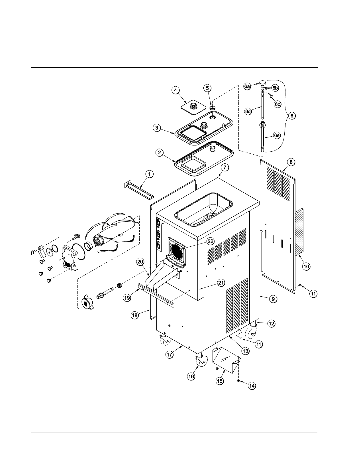
Section 4 Operator Parts Identification
C001 Exploded View
110304
Figure 1
8
Models C001 & C002Operator Parts Identification
Page 13

C001 Exploded View Parts Identification
ITEM DESCRIPTION PART NO.
1 PAN-DRIP 11-5/8 LONG 027503
2 GASKET-HOPPER COVER 055356
3 COVER-HOPPER-LARGE 054732
4 COVER-HOPPER-SMALL 054733
5 BUSHING-COVER-HOPPER 054734
6 CONTROL A.-FLOW REG. X59788
6a KNOB-INNER-REG. TUBE 059785
6b O-RING-12.42 MM ID X 1.4 MM 062451
6c PIN-QUICK RELEASE 3/16 X 1 S 027813
6d TUBE-INNER-REGULATOR 059787
6e REGULATOR A.-FLOW OUTER 059784
7 TRIM-REAR CORNER L. 067971
8 PANEL-REAR 066551
9 TRIM-REAR CORNER R. 067972
10 FILTER-AIR-18.00LX13.50HX.70 052779-3
ITEM DESCRIPTION PART NO.
11 SCREW-1/4-20X3/8 SLTD RND 011694
12 ADAPTOR A.-CASTER X18915
13 PANEL-SIDE-RIGHT * A/C 067968
14 NUT-10-32 WHIZ FLANGE
LOCKNUT
15 DEFLECTOR-BLOWER
EXHAUST
16 CASTER-4” SWV 5/8 STEM W/
BRAKE
17 PANEL-LOWER FRONT 066544
18 PANEL-SIDE-LEFT *A/C 067967
19 BUMPER 054487
20 CHUTE-CUSTARD-LONG 054633
*21 PANEL A.-FRONT-COMPLETE X66542-27
22 STUD-FREEZER 034035
*PANEL A.-UPPER FRONT (PANEL ONLY) = X66550
020983
047912
034081
140801
Models C001 & C002 Operator Parts Identification
9
Page 14
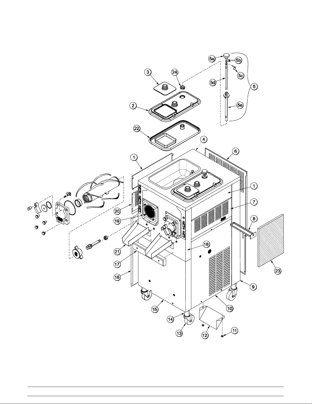
C002 Exploded View
131021
Figure 2
10
Models C001 & C002Operator Parts Identification
Page 15

C002 Exploded View Parts Identification
ITEM DESCRIPTION PART NO.
1 PANEL-SIDE TOP 029978
2 COVER-HOPPER-LARGE 054732
3 COVER-HOPPER-SMALL 054733
4 TRIM-REAR CORNER LEFT 054458
5 CONTROL A.-FLOW REG. X59788
5a KNOB-INNER REG. TUBE 059785
5b O-RING-12.42 ID X 1.4 W 062451
5c PIN-QUICKRELEASE 3/16 X 1 027813
5d TUBE-INNER REGULATOR 059787
5e REGULATOR A.-FLOW-OUTER 059784
6 PANEL-REAR 053782
7 PANEL-UPPER SIDE RIGHT 054449
8 PAN-DRIP 11-5/8 LONG 027503
9 TRIM-REAR CORNER RIGHT 054459
10 PANEL A.-SIDE RIGHT X66497
11 NUT-10-32 WHIZ FLANGE
LOCKNUT
020983
ITEM DESCRIPTION PART NO.
12 DEFLECTOR-BLOWER
EXHAUST
13 CASTER-4” SWV 5/8 STEM W/
BRAKE
14 ADAPTOR·A.-CASTER X18915
15 PANEL-FRONT-LOWER 066507
16 PANEL A.-SIDE LEFT X66496
17 BUMPER-FRONT 054487
*18 PANEL A.-FRONT-COMPLETE X66509-27
19 STUD-FREEZER 034035
20 PANEL-UPPER SIDE LEFT 054448
21 CHUTE-CUSTARD-LONG 054633
22 GASKET-HOPPER COVER 055356
23 FILTER-AIR 18 L X 13.5 H .70W 052779-3
24 BUSHING-COVER-HOPPER 054734
*PANEL A.-UPPER FRONT (PANEL ONLY) = X66493
047912
034081
080610
Models C001 & C002 Operator Parts Identification
11
Page 16

Dasher (Beater) and Door Assembly
ITEM DESCRIPTION PART NO.
1
CAP-DOOR-STEM 055179
2
ARM-HANDLE 055183
3
PLATE-DRAW 054445
4
O-RING-2-3/4 OD X .139W-70 055182
5
SCREW-DOOR-STEM 055180
6
O-RING-.563 OD X .070W-#013 043758
7
BEARING-FRONT 013116
8
BLADE-SCRAPER 054485
Figure 3
12
ITEM DESCRIPTION PART NO.
9
BAFFLE-SHORT 054481
10
SHAFT-DASHER DRIVE 054484
11
SEAL-DRIVE SHAFT 032560
12
DASHER A.-COMPLETE X54483
13
O-RING-6 IN OD X 5 3/4 ID X 1/8 033493
14
DOOR-C002 X55178-SER
15
NUT-STUD 034034
16
NUT-STUD 021508
Models C001 & C002Operator Parts Identification
Page 17

Accessories
Figure 4
ITEM DESCRIPTION PART NO.
1 SANITIZER- STERA SHEEN 055492
2 LUBRICANT- TAYLOR 4 OZ. 047518
3 KIT A.- TUNE UP X54630- 1
4 PAIL - 10 QT. 013163
Models C001 & C002 Operator Parts Identification
ITEM DESCRIPTION PART NO.
5 BRUSH- REAR BEARING 013071
6 BRUSH- DOUBLE ENDED 013072
7 BRUSH- MIX PUMP BODY 023316
8 BRUSH- DRAW VALVE 013073
140801
13
Page 18

Section 5 Important: To the Operator
C001
ITEM DESCRIPTION
1 LIGHT- HOPPER REFRIG. ON/OFF
2 SWITCH- HOPPER REFRIG. ON/OFF
3 LIGHT- MIX LOW
4 LIGHT- FREEZE MODE
5 SWITCH- FREEZE/CHILL MODE
110304
Figure 5
14
ITEM DESCRIPTION
6 LIGHT- CHILL MODE
7 LIGHT- DASHER ON/OFF
8 SWITCH- DASHER ON/OFF
9 BUTTON- RESET
Models C001 & C002Important: To the Operator
Page 19

C002
Figure 6
ITEM DESCRIPTION
1 LIGHT- HOPPER REFRIG. ON/OFF
2 SWITCH- HOPPER REFRIG. ON/OFF
3 LIGHT- MIX LOW
4 LIGHT- FREEZE MODE
5 SWITCH- FREEZE/CHILL MODE
Models C001 & C002 Important: To the Operator
ITEM DESCRIPTION
6 LIGHT- CHILL MODE
7 LIGHT- DASHER ON/OFF
8 SWITCH- DASHER ON/OFF
9 BUTTON- RESET
080930
15
Page 20

Symbol Definitions
To better communicate in the International arena, the
words on many of our operator switches and buttons
have symbols to indicate their functions. Your Taylor
equipment is designed with these International
symbols.
The following chart identifies the symbol definitions
used on the operator switches.
= HOPPER REFRIGERATION
=ON
=OFF
=MIXLOW
= FREEZE MODE
= CHILL MODE
= DASHER
16
Models C001 & C002Important: To the Operator
Page 21

Section 6 Operating Procedures
The Model C001 is a single flavor custard freezer with
a 20 quart (18.9 liter) hopper. The Model C002 is a two
flavor custard freezer with two 20 quart (18.9 liter)
hoppers. Mix flows by gravity through an adjustable
flow regulator into the freezing cylinder(s). These units
have been designed to produce rich tasting custard
product that can be drawn off and served from a
dipping cabinet. The overrun is low; typically 15- 20%,
and varies depending on the mix formulation and the
finished product temperature 17 to 19_.F (- 8.3 to
-7.2_C).
The Model C002 has been selected to illustrate the
pictured step- by- step operating procedures for both
models contained in this manual. These models, for
practical purposes of operation, are the same.
We begin our instructions at the point where we find
the parts disassembled and laid out to air dry from the
previous brush cleaning.
The following procedures will show you how to
assemble the parts into the freezer, sanitize them, and
prime the freezer with fresh mix.
If you are disassembling the freezer for the first time
or need information to get to this starting point in our
instructions, turn to page 24 , “Disassembly” and start
there.
Note: When lubricating parts, always use an
approved food grade lubricant (example: Taylor
Lube).
Figure 7
Insert the drive shaft into the freezing cylinder, hex end
first, and into the rear shell bearing until the seal fits
securely over the rear shell bearing. Engage the hex
end firmly into the drive coupling. Be sure the drive
shaft fits into the drive coupling without binding.
Assembly
MAKE SURE THE DASHER POWER
SWITCH IS IN THE “OFF” POSITION. Failure to
follow this instruction may cause severe personal
injury to fingers or hands from hazardous moving
parts.
Step 1
Install the drive shaft. Lubricate the groove and shaft
portion that comes in contact with the bearing on the
dasher drive shaft. Slide the seal over the shaft and
groove until it snaps into place. DO NOT lubricate the
hex end of the drive shaft. Fill the inside portion of the
seal with 1/4” (6 mm) more lubricant and lubricate the
flat side of the seal that fits onto the rear shell bearing.
Models C001 & C002 Operating Procedures
17
Figure 8
Page 22

Step 2
Install the short baffle into the freezing cylinder, narrow
end first. Slide it over the end of the drive shaft.
Figure 9
Step 3
Assemble the dasher. Take one of the scraper blades
and slip it under the hook at the front of the dasher.
Wrap the blade around the dasher, following the helix
and pushing the blade down onto the helix as you
wrap. At the back end of the dasher, slip the blade
under the hook. Repeat this step for the other scraper
blades.
Figure 11
Note: A dasher installation/removal tool is available
to assist in the installation and removal of the dasher.
To install the dasher, insert the short bars of the tool
into the slots in the end of the dasher. Using the long
bar of the tool, push the dasher until it is properly
installed in the freezing cylinder.
Figure 10
Step 4
Install the dasher. Slide the dasher into the freezing
cylinder and over the end of the drive shaft. The dasher
should fit snugly, but not so tightly that the dasher
cannot be turned slightly to engage the drive shaft. If
the dasher slides in too easily with little or no
resistance, there will not be enough force against the
dasher to hold the blades in place. If this is the case,
contact your authorized T aylor service technician.
090106
Figure 12
Install the front bearing into the front of the dasher
assembly.
Figure 13
18
Models C001 & C002Operating Procedures
11197
Page 23

Step 5
Assemble the freezer door. Install the draw plate
o- ring onto the plate and lubricate.
10317
R
E
B
U
L
Figure 14
Install the two stem screw o- rings onto the stem screw
and lubricate.
10329
R
10328
Figure 16
Turn the door over and install the large door o- ring.
Place a small amount of lubricant on the o- ring, just
enough to hold the o- ring in place.
10325
R
Figure 15
Place the stem screw through the back of the door.
With the door in a horizontal position, install the draw
plate. Align the handle with the stem screw and the
draw plate. Hand- tighten the stem cap onto the stem
screw.
Figure 17
Step 6
Install the freezer door. Seat the door flush with the
freezing cylinders. With the door seated on the freezer
studs, install the stud nuts (handscrews). The short
stud nuts go on the bottom and the long stud nuts go
on top. Tighten equally in a crisscross pattern to insure
the door is snug.
10326
Figure 18
Models C001 & C002 Operating Procedures
19
Page 24

Step 7
Assemble the flow regulator assembly. Install the
two o- rings onto the inner flow regulator. Lubricate the
o- rings. Install the knob onto the end of the inner flow
regulator and secure it with the quick release pin.
Insert the inner flow regulator into the outer flow
regulator.
Sanitizing
Step 1
Prepare an approved 100 PPM sanitizing solution
(examples: 2- 1/2 gal. [9.5 liters] of Kay- 5R
or 2 gal. [7.6 liters] of Stera- SheenR). USE WARM
WATER AND FOLLOW THE MANUFACTURER’S
SPECIFICATIONS.
Step 2
Pour the sanitizing solution into the hopper.
Step 3
While the solution is flowing into the freezing cylinder,
brush clean the mix hopper. When cleaning the
hopper, take particular care in brushing the mix inlet
hole and the flow regulator.
Figure 19
Step 8
Place the assembled flow regulator into the hopper for
sanitizing.
Step 9
Install the rear bearing drip pan.
Step 10
Put the sanitized hopper gasket on the hopper cover.
17042
Figure 20
Step 4
Place an empty pail under the draw plate. The pail can
be hung from the hand screws on the freezer door.
Step 5
Place the dasher motor power switch in the ON
position for 5 minutes.
Step 6
In order to avoid having sanitizer splashing out when
the draw plate is opened, place the dasher motor
switch in the OFF position. Open the draw plate and
place the dasher motor switch in the ON position. Drain
the sanitizer into an empty pail. Place the dasher motor
switch in the OFF position and close the draw plate.
KEEP FINGERS OUT OF FILL AND
DISCHARGE OPENINGS! Failure to do so may result
in severe personal injury, contaminated product, or
component damage.
Repeat these steps for the other side of the freezer.
140801
Repeat these steps for the other side of the freezer.
20
Models C001 & C002Operating Procedures
Page 25

Priming for Continuous Run
Step 1
With sanitized hands, remove the flow regulator
assembly from the mix hopper and set it on a clean, dry
surface. Place an empty pail under the draw plate.
Step 2
Pour 1 - 2 cups (1/2 liter) of mix into the hopper to
remove the remaining sanitizing solution from the
freezing cylinder.
Step 3
Open the draw plate on the freezer door and place the
dasher motor power switch in the ON position.
Repeat steps 1 - 2 for the other side of the freezer.
KEEP FINGERS OUT OF FILL AND
DISCHARGE OPENINGS! Failure to do so may result
in severe personal injury, contaminated product, or
component damage.
Step 4
Install the large hopper cover on the hopper.
Step 5
With sanitized hands, install the flow regulator
through the hopper cover. Align the flow regulator with
the slots on the hopper cover. The flow regulator can
be positioned to allow the numbers to be read from the
front, back or either side.
Note: The flow regulator opening is adjustable. The
smaller the number, the less product will flow into the
freezing cylinder. The larger the number, the more
product will flow into the freezing cylinder. The
numbers are only guides. The flow regulator may be
adjusted to any point in between the numbers.
Figure 21
Step 10
Install the chute on the two holding collars under the
door and position it over the holding cabinet opening.
Step 6
Pour mix into the hopper and fill it to 1/2” (13 mm)
below the air inlet on the flow regulator.
Step 7
Place the FREEZE/CHILL switch in the FREEZE
position and the hopper refrigeration switch in the ON
position.
Step 8
Allow the unit to run for 2 minutes. Set the flow
regulator between S - 1.
Step 9
Install the small hopper lid.
Repeat steps 4 - 9 for the other side of the freezer.
Figure 22
Step 11
Leave the draw plate closed until product can be seen
coming out around the edges of the draw plate
(approximately 3 to 4 minutes) and then open the draw
plate all the way.
140801
Models C001 & C002 Operating Procedures
21
Page 26

Step 12
With the draw plate open and a full ribbon of product
dispensing at the proper frozen consistency, the flow
regulator will need to be opened further to prevent the
freezing cylinder from starving.
IMPORTANT: If the freezing cylinder becomes
starved and begins to make noise, increase the
number on the flow regulator. Wait one or two minutes.
If the noise continues, place the FREEZE/CHILL
switch in the OFF position until product begins flowing
from the door. Place the FREEZE/CHILL switch back
in the FREEZE mode position. Repeat these steps as
necessary to adjust for a specific mix. DO NOT TURN
DASHER OFF!
If the product becomes too soft, decrease the flow
regulator opening.
Repeat steps 10 - 12 for the other side of the
freezer.
To Restart the Continuous Run:
Step 1
Place the dasher power switch in the ON position.
Step 2
Place the FREEZE/CHILL switch in the FREEZE
mode position. Wait one minute.
Step 3
Open the flow regulator back to the previous run
setting.
Step 4
Once product starts coming out around the edges of
the draw plate, open the draw plate.
Closing Procedure
Stopping a Continuous Run for a
ShortPeriodofTime
Step 1
Leave the flow regulator in the DOWN position, but
adjust the setting to 0. Wait 30 seconds.
Step 2
Place the FREEZE/CHILL switch in the CHILL mode
position. Wait two minutes.
Step 3
Place the dasher power switch in the OFF position.
Step 4
Close the draw plate.
WARNING: The dasher motor power
switch must be placed in the OFF position when
the draw plate is closed. Failure to comply can result
in serious equipment damage and possible injury to
the operator.
To disassemble your unit, the following items will be
needed:
S Two cleaning pails
S Necessary brushes (provided with freezer)
S Cleaner
S Single service towels
22
Models C001 & C002Operating Procedures
Page 27

Draining Product From The
Freezing Cylinder
Step 1
Place the FREEZE/CHILL and the hopper
refrigeration switches in the OFF position.
Step 2
Remove the flow regulator assembly, hopper covers,
gaskets, discharge chute and rear bearing drip pan.
Take these parts to the sink for cleaning in an
approved cleaning solution (examples: Kay- 5R or
Stera- SheenR).
Step 3
If local health codes permit the use of rerun,place
a sanitized, NSF approved stainless steel rerun
container beneath the draw plate. Place the dasher
power switch in the ON position. Drain the remaining
product into the rerun container. When the flow of
product stops, place the dasher power switch in the
OFF position. Place the sanitized lid on the rerun
container and place it in the walk- in cooler.
Note: If local health codes DO NOT permit theuse
of rerun, the product must be discarded. Follow the
instructions in the previous step, except drain the
product into a pail and properly discard the mix.
Repeat steps 1 through 3 for the other side of the
freezer.
ALWAYS FOLLOW LOCAL HEALTH CODES.
Rinsing
Step 1
With a pail beneath the draw plate, pour two gallons
(7.6 liters) of cool clean water into the mix hopper.
With the brushes provided, scrub the mix hopper.
Figure 23
Step 2
Place the dasher motor power switch in the ON
position. Agitate for five minutes. Drain all the rinse
water from the freezing cylinder.
Repeat steps 1 through 2 until the water is clear.
Step 3
Once all the rinse water has drained, place the dasher
motor power switch in the OFF position.
Repeat steps 1 through 3 for the other side of the
freezer.
140801
Models C001 & C002 Operating Procedures
23
Page 28

Cleaning
Disassembly
Step 1
Prepare an approved 100 PPM cleaning solution
(examples: 2- 1/2 gal. [9.5 liters] of Kay- 5R
or 2 gal. [7.6 liters] of Stera- SheenR). USE WARM
WATER AND FOLLOW THE MANUFACTURER’S
SPECIFICATIONS.
Step 2
With the draw plate closed, pour the cleaning solution
into the mix hopper.
MAKE SURE THE DASHER POWER
SWITCH IS IN THE “OFF” POSITION. Failure to
follow this instruction may result in severe personal
injury to fingers or hands from hazardous moving
parts.
Step 1
Remove the flow regulators from the mix hoppers.
Remove the handscrews, freezer doors, dashers,
scraper blades, chutes, and drive shafts from the
freezing cylinders. Take these parts to the sink for
cleaning.
Note: A dasher installation/removal tool is available
to assist in the installation and removal of the dasher.
To remove the dasher, insert the two short bars of the
tool into the slots in the end of the dasher. Holding the
long bar of the tool, turn the tool clockwise to lock the
tool in the dasher, and then pull the dasher out.
Figure 24
Step 3
While the solution is flowing into the freezing cylinder,
brush clean the mix hopper.
Step 4
Place an empty pail beneath the draw plate.
Step 5
Place the dasher motor switch in the ON position.
Step 6
Allow all of the solution to drain.
Repeat steps 1 through 6 for the other side of the
freezer.
090106
Figure 25
Brush Cleaning
Step 1
Prepare a sink with an approved cleaning solution
(examples: Kay- 5R or Stera- SheenR). USE WARM
WATER AND FOLLOW THE MANUFACTURER’S
SPECIFICATIONS. If another approved cleaner is
used, dilute it according to the label instructions.
(IMPORTANT: Follow the label directions. Too
STRONG of a solution can cause parts damage, while
too MILD of a solution will not provide adequate
cleaning.) Make sure all brushes provided with the
freezer are available for brush cleaning.
24
Models C001 & C002Operating Procedures
Page 29

Step 2
Remove the seals from the drive shafts.
Figure 26
Step 3
From the freezer door remove:
S front bearings
S handle arms
S plates
S stem caps
S stem screws
Step 4
Remove all o- rings.
Note: To remove o- rings, use a single service towel
to grasp the o- ring. Apply pressure in an upward
direction until the o- ring pops out of its groove. With
the other hand, push the top of the o- ring forward and
it will roll out of the groove and can be easily removed.
If there is more than one o- ring to be removed, always
remove the rear o- ring first. This will allow the o- ring
to slide over the forward rings without falling into the
open grooves.
Step 6
Remove the hopper cover gasket from the hopper
cover.
Step 7
Return to the freezer with a small amount of cleaning
solution. Brush clean the mix inlet holes in the mix
hoppers.
Figure 28
Step 8
Brush clean the rear shell bearings at the back of the
freezing cylinders with the black bristle brush.
Step 5
Remove the o- rings from the inner flow regulators.
Figure 29
Step 9
Thoroughly brush clean all disassembled parts in the
cleaning solution, making sure all lubricant and mixfilm
is removed. Place all the cleaned parts on a clean, dry
surface to air dry overnight.
Step 10
Figure 27
Models C001 & C002 Operating Procedures
Wipe clean all exterior surfaces of the freezer.
25
Page 30

Section 7 Important: Operator Checklist
During Cleaning and Sanitizing
ALWAYS FOLLOW LOCAL HEALTH CODES.
Cleaning and sanitizing schedules are governed
by federal, state, or local regulatory agencies, and
must be followed accordingly. If the unit has a
“Standby mode”, it must not be used in lieu of
proper cleaning and sanitizing procedures and
frequencies set forth by the ruling health
authority. The following check points should be
stressed during the cleaning and sanitizing
operations.
CLEANING AND SANITIZING MUST BE
PERFORMED DAILY.
T roubleshooting Bacterial Count
j 5. IF LOCAL HEALTH CODES PERMIT THE
USE OF RERUN, make sure the mix rerun is
stored in a sanitized, covered stainless steel
container and used the following day. DO NOT
prime the machine with rerun. When using
rerun, skim off the foam and discard. Mix the
rerun with fresh mix in a ratio of 50/50 during the
days operation.
j 6. On a designated day of the week, run the mix as
low as feasible and discard it after closing. This
will break the rerun cycle and reduce the
possibility of high bacteria and coliform counts.
j 7. Properly prepare the cleaning and sanitizing
solutions. Read and follow the label directions
carefully. Too strong of a solution may damage
the parts and too weak of a solution will not do
an adequate job of cleaning or sanitizing.
j 8. The temperature of the mix in the mix hopper
and walk- in cooler should be below 40_F
(4.4_C).
Regular Maintenance Checks
j 1. Thoroughly clean and sanitize the machine
regularly, including complete disassembly and
brush cleaning.
j 2. Use all brushes supplied for thorough cleaning.
The brushes are specially designed to reach all
mix passageways.
j 3. Use the white bristle brush to clean the mix inlet
hole which extends from the mix hopper down
to the rear of the freezing cylinder.
j 4. Use the black bristle brush to thoroughly clean
the rear shell bearing located at the rear of the
freezing cylinder. Be sure there is a generous
amount of cleaning solution on the brush.
j 1. Replace scraper blades that are nicked or
damaged. Before installing the dasher
assembly, be certain that the scraper blades are
properly attached to the dasher shaft.
j 2. Check the rear shell bearing for signs of wear
(excessive mix leakage in rear drip pan) and be
certain it is properly cleaned.
j 3. Using a long brush and a cloth towel, keep the
rear shell bearing and the female hex drive
socket clean and free of lubricant and mix
deposits.
j 4. Dispose of o- rings and seals if they are worn,
torn, or fit too loosely, and replace with new
ones.
26
Models C001 & C002Important: Operator Checklist
Page 31

j 5. Follow all lubricating procedures as outlined in
“Assembly”.
j 6. If your machine is air cooled, check the
condenser for an accumulation of dirt and lint.
Dirty condensers will reduce the efficiency and
capacity of the machine. Condensers should be
cleaned monthly with a soft brush. Never use
screwdrivers or other metal probes to clean
between the fins.
Note: For machines equipped with an air filter,
it will be necessary to vacuum the filters on a
monthly schedule.
Caution: Always disconnect
electrical power prior to cleaning the
condenser. Failure to follow this instruction may
result in electrocution.
j 7. If your machine is water cooled, check the water
lines for kinks or leaks. Kinks can occur when
the machine is moved back and forth for
cleaning or maintenance purposes.
Deteriorated or cracked water lines should be
replaced only by an authorized Taylor
distributor.
Winter Storage
If the place of business is to be closed during the winter
months, it is important to protect the freezer by
following certain precautions, particularly if the
building is subject to freezing conditions.
Disconnect the freezer from the main power source to
prevent possible electrical damage.
On water cooled freezers, disconnect the water
supply. Relieve pressure on the spring in the water
valve. Use air pressure on the outlet side to blow out
any water remaining in the condenser. This is
extremely important. Failure to follow this procedure
may cause severe and costly damage to the
refrigeration system.
Your local Taylor Distributor can perform this winter
storage service for you.
Wrap detachable parts of the freezer such as dasher,
blades, dasher shaft, and freezer door, and place them
in a protected dry place. Rubber trim parts and gaskets
can be protected by wrapping them with
moisture- proof paper. All parts should be thoroughly
cleaned of dried mix or lubrication which attract mice
and other vermin.
It is recommended that an authorized service
technician perform winter storage draining, to insure
all water has been removed. This will guard against
freezing and rupturing of the components.
080130
Models C001 & C002 Important: Operator Checklist
27
Page 32

Section 8 Troubleshooting Guide
PROBLEM PROBABLE CAUSE REMEDY PAG E
REF.
1. Compressor will not run. a. Dasher motor switch
and/or FREEZE/CHILL
switch are in the wrong
position.
a. Place the dasher motor
switch and/or the
FREEZE/CHILL switch in
the “FREEZE” position.
b. The contactor is faulty. b. Call service technician.
c. Compressor has burned
c. Call service technician.
out.
d. The fuse or circuit breaker
has blown.
e. Tripped overload
(compressor).
d. Replace fuse/turn on
breaker.
e. Place the power switch in
“OFF”. Allow compressor
to cool and the overload to
close before returning the
power switch to “ON”.
f. Freezer door is off. f. Install the freezer door.
2. Head pressure is too high. a. Condenser is dirty. a. Clean the condenser.
b. Refrigerant overcharge. b. Call service technician.
c. Fan is faulty. c. Call service technician.
3. Head pressure is too low. a. Shortage of refrigerant. a. Call service technician.
15
---
---
2
---
19
27
---
---
---
4. Liquid line is hot. a. Shortage of refrigerant. a. Call service technician.
5. Excessive mix leakage
through the rear of the
a. Worn or missing drive
shaft seal.
a. Replace worn, nicked or
missing drive shaft seal.
unit into the drip pan.
b. Inadequate lubrication. b. Lubricate properly.
6. Product is not being fed
into the freezing cylinder.
a. Inadequate mix in hopper.
(mix out light illuminated)
b. Incorrect usage of the mix
flow regulator.
a. Fill hopper with mix.
b. Follow the correct flow
regulator adjustment
procedures.
28
Models C001 & C002Important: Operator Checklist
--17
17
21
21
Page 33

PROBLEM PROBABLE CAUSE REMEDY PAG E
REF.
7. No product is being
dispensed with the flow
control open.
a. Frozen product. a. Scrape product away from
the door.
b. Dasher is rotating
b. Call service technician.
counter- clockwise.
c. Inadequate mix in hopper.
c. Fill hopper with mix.
(mix out light illuminated)
d. Flow regulator is plugged. d. Brush clean the flow
regulator.
8. Product is too soft. a. Bad scraper blades. a. Replace scraper blades.
b. Dirty condenser
b. Clean condenser monthly.
(air- cooled).
c. Mix is outdated. c. Use fresh mix.
d. Refrigerant shortage. d. Call service technician.
e. Flow regulator setting is
e. Call service technician.
too high.
9. Door spout is plugged. a. Poor scraping. a. Replace scraper blades.
b. The dasher assembly is
damaged.
b. Inspect and replace if
necessary.
---
---
21
25
18
27
---
---
---
18
18
10. No freezer operation
when unit is placed in any
mode of operation.
a. The unit is unplugged. a. Plug in the unit.
b. Circuit breaker is off or
fuse is blown.
1 1. Product is too stiff. a. Flow regulator is set too
low.
b. Flow regulator is
incorrectly assembled or
is malfunctioning.
12. The mix in the hopper is
too cold.
13. The mix in the hopper is
too warm.
a. Temperature is out of
adjustment.
a. Temperature is out of
adjustment.
b. Turn on the circuit breaker
/ replace fuse.
a. Adjust the flow regulator
setting.
b. Re- assemble the flow
regulator. If flow regulator
malfunctions, call service
technician.
a. Call service technician.
a. Call service technician.
---
---
21
20
---
---
Models C001 & C002 Important: Operator Checklist
29
Page 34

PROBLEM PROBABLE CAUSE REMEDY PAG E
REF.
14. Drive shaft is stuck in the
gear box coupling.
a. The corners of the drive
shaft, coupling, or both
are rounded.
a. Replace the necessary
component(s). Do not
lubricate the end of the
drive shaft.
b. Mix and lubricant have
collected in the drive
b. Brush clean the rear shell
bearing area regularly.
coupling.
15. Freezing cylinder walls
are scored.
16. A “chirping” or squealing
sound is coming from the
freezing cylinder.
a. The dasher assembly is
damaged.
b. The front bearing is either
missing or is worn.
a. The freezing cylinder is
starved for mix.
a. Replace the dasher
assembly.
b. Install / replace front
bearing.
a. Adjust the flow control to
allow more mix to enter
the freezing cylinder.
17. The reset is tripping. a. The belt is too tight. a. Call service technician.
b. The amperage is too high. b. Call service technician.
c. The dasher is rotating
c. Call service technician.
counter- clockwise.
d. Faulty reset switch. d. Call service technician.
17
25
18
18
21
---
---
---
---
e. The suction pressure is
too low.
f. The shaft is too far into
the gearbox or is pushing
on the door.
g. Product is frozen in the
freezing cylinder.
e. Call service technician.
f. Call service technician.
g. Call service technician.
---
---
---
30
Models C001 & C002Important: Operator Checklist
Page 35

Section 9 Parts Replacement Schedule
PART DESCRIPTION EVERY 3
MONTHS
Front Bearing X
Inner Flow Regulator O- Rings X
Draw Plate O- Ring X
Freezer Door O- Ring X
Drive Shaft Seal X
Scraper Blades X
Black Bristle Brush - 1” x 2” Inspect & Replace
Double Ended Brush Inspect & Replace
White Bristle Brush - 3” x 7” Inspect & Replace
EVERY 6
MONTHS
if Necessary
if Necessary
if Necessary
ANNUALLY
Minimum
Minimum
Minimum
Models C001 & C002 Parts Replacement Schedule
31
Page 36

Section 1 0 Limited Warranty on Equipment
TAYLOR COMPANY LIMITED WARRANTY ON FREEZERS
Taylor Company, a division of Carrier Commercial Refrigeration, Inc. (“T aylor”) is pleased to provide this limited
warranty on new Taylor-branded freezer equipment available from Taylor to the market generally (the “Product”)
to the original purchaser only.
LIMITED WARRANTY
Taylor warrants the Product against failure due to defect in materials or workmanship under normal use and
service as follows. All warranty periods begin on the date of original Product installation. If a part fails due to
defect during the applicable warranty period, Taylor, through an authorized Taylor distributor or service agency,
will provide a new or re- manufactured part, at T aylor’s option, to replace the failed defective part at no charge for
the part. Except as otherwise stated herein, these are T aylor’s exclusive obligations under this limited warranty for
a Product failure. This limited warranty is subject to all provisions, conditions, limitations and exclusions listed
below and on the reverse (if any) of this document.
Product
Soft Serve
Frozen Yogurt
Shakes
Smoothies
Frozen Beverage
Batch Desserts
1. If the date of original installation of the Product cannot be verified, then the limited warranty period begins
ninety (90) days from the date of Product manufacture (as indicated by the Product serial number). Proof of
purchase may be required at time of service.
2. This limited warranty is valid only if the Product is installed and all required service work on the Product is
performed by an authorized Taylor distributor or service agency, and only if genuine, new T aylor parts are
used.
3. Installation, use, care, and maintenance must be normal and in accordance with all instructions contained in
the Taylor Operator’s Manual.
Insulated shell assembly Five (5) years
Refrigeration compressor
(except service valve)
Beater motors Two (2) years
Beater drive gear Two (2) years
Printed circuit boards and
Softech controls beginning
with serial number H8024200
Parts not otherwise listed in
this table or excluded below
LIMITED WARRANTY CONDITIONS
Part Limited Warranty Period
Five (5) years
Two (2) years
One (1) year
4. Defective parts must be returned to the authorized Taylor distributor or service agency for credit.
5. The use of any refrigerant other than that specified on the Product’s data label will void this limited warranty.
LIMITED WARRANTY EXCEPTIONS
This limited warranty does not
1. Labor or other costs incurred for diagnosing, repairing, removing, installing, shipping, servicing or handling of
defective parts, replacement parts, or new Products.
2. Normal maintenance, cleaning and lubrication as outlined in the Taylor Operator’s Manual, including cleaning
of condensers.
131122
cover:
32
Models C001 & C002Limited Warranty on Equipment
Page 37

3. Replacement of wear items designated as Class “000” parts in the Taylor Operator’s Manual.
4. External hoses, electrical power supplies, and machine grounding.
5. Parts not supplied or designated by Taylor, or damages resulting from their use.
6. Return trips or waiting time required because a service technician is prevented from beginning warranty
service work promptly upon arrival.
7. Failure, damage or repairs due to faulty installation, misapplication, abuse, no or improper servicing,
unauthorized alteration or improper operation or use as indicated in the Taylor Operator’s Manual, including
but not limited to the failure to use proper assembly and cleaning techniques, tools, or approved cleaning
supplies.
8. Failure, damage or repairs due to theft, vandalism, wind, rain, flood, high water, water, lightning, earthquake
or any other natural disaster, fire, corrosive environments, insect or rodent infestation, or other casualty,
accident or condition beyond the reasonable control of Taylor; operation above or below the electrical or
water supply specification of the Product; or components repaired or altered in any way so as, in the
judgment of the Manufacturer, to adversely affect performance, or normal wear or deterioration.
9. Any Product purchased over the Internet.
10. Failure to start due to voltage conditions, blown fuses, open circuit breakers, or damages due to the
inadequacy or interruption of electrical service.
1 1. Electricity or fuel costs, or increases in electricity or fuel costs from any reason whatsoever.
12. Damages resulting from the use of any refrigerant other than that specified on the Product’s data label will
void this limited warranty.
13. Any cost to replace, refill or dispose of refrigerant, including the cost of refrigerant.
14. ANY SPECIAL, INDIRECT OR CONSEQUENTIAL PROPERTY OR COMMERCIAL DAMAGE OF ANY
NATURE WHATSOEVER. Some jurisdictions do not allow the exclusion of incidental or consequential
damages, so this limitation may not apply to you.
This limited warranty gives you specific legal rights, and you may also have other rights which vary from
jurisdiction to jurisdiction.
LIMITA TION OF WARRANTY
THIS LIMITED WARRANTY IS EXCLUSIVE AND IS IN LIEU OF ALL OTHER WARRANTIES, CONDITIONS
AND/OR REMEDIES UNDER THE LAW, INCLUDING ANY IMPLIED WARRANTIES OR CONDITIONS OF
MERCHANTABILITY OR FITNESS FOR A PARTICULAR PURPOSE. THE ORIGINAL OWNER’S SOLE
REMEDY WITH RESPECT TO ANY PRODUCTS SHALL BE REPAIR OR REPLACEMENT OF DEFECTIVE
COMPONENTS UNDER THE TERMS OF THIS LIMITED WARRANTY. ALL RIGHTS TO CONSEQUENTIAL
OR INCIDENTAL DAMAGES (INCLUDING CLAIMS FOR LOST SALES, LOST PROFITS, PRODUCT LOSS,
PROPERTY DAMAGES OR SERVICE EXPENSES) ARE EXPRESSLY EXCLUDED. THE EXPRESS
WARRANTIES MADE IN THIS LIMITED WARRANTY MAY NOT BE ALTERED, ENLARGED, OR CHANGED
BY ANY DISTRIBUTOR, DEALER, OR OTHER PERSON, WHATSOEVER.
LEGAL REMEDIES
The owner must notify Taylor in writing, by certified or registered letter to the following address, of any defect or
complaint with the Product, stating the defect or complaint and a specific request for repair, replacement, or other
correction of the Product under warranty, mailed at least thirty (30) days before pursuing any legal rights or
remedies.
Taylor Company
a division of Carrier Commercial Refrigeration, Inc.
750 N. Blackhawk Blvd.
Rockton, IL 61072, U.S.A.
Models C001 & C002 Limited Warranty on Equipment
33
Page 38

Section 11 Limited Warranty on Parts
TAYLOR COMPANY LIMITED WARRANTY ON TAYLOR GENUINE PARTS
Taylor Company, a division of Carrier Commercial Refrigeration, Inc. (“T aylor”) is pleased to provide this limited
warranty on new Taylor genuine replacement components and parts available from Taylor to the market generally
(the “Parts”) to the original purchaser only.
LIMITED WARRANTY
Taylor warrants the Parts against failure due to defect in materials or workmanship under normal use and service
as follows. All warranty periods begin on the date of original installation of the Part in the Taylor unit. If a Part fails
due to defect during the applicable warranty period, Taylor, through an authorized Taylor distributor or service
agency, will provide a new or re- manufactured Part, at T aylor’s option, to replace the failed defective Part at no
charge for the Part. Except as otherwise stated herein, these are Taylor’s exclusive obligations under this limited
warranty for a Part failure. This limited warranty is subject to all provisions, conditions, limitations and exclusions
listed below and on the reverse (if any) of this document.
Part’s Warranty Class Code or Part
Class 103 Parts¹ Three (3) months
Class 212 Parts² Twelve (12) months
Class 512 Parts Twelve (12) months
Class 000 Parts No warranty
Taylor Part #072454 (Motor- 24VDC *C832/C842*) Four (4) years
LIMITED WARRANTY CONDITIONS
1. If the date of original installation of the Part cannot be otherwise verified, proof of purchase may be required
at time of service.
2. This limited warranty is valid only if the Part is installed and all required service work in connection with the
Part is performed by an authorized Taylor distributor or service agency.
3. The limited warranty applies only to Parts remaining in use by their original owner at their original installation
location in the unit of original installation.
4. Installation, use, care, and maintenance must be normal and in accordance with all instructions contained in
the Taylor Operator’s Manual.
5. Defective Parts must be returned to the authorized Taylor distributor or service agency for credit.
6. This warranty is not intended to shorten the length of any warranty coverage provided pursuant to a separate
Taylor Limited Warranty on freezer or grill equipment.
Limited Warranty Period
7. The use of any refrigerant other than that specified for the unit in which the Part is installed will void this
limited warranty.
1, 2
Except that Taylor Part #032129SER2 (Compressor-Air-230V SERV) and Taylor Part #075506SER1
(Compressor-Air-115V 60HZ) shall have a limited warranty period of twelve (12) months when used in Taylor
freezer equipment and a limited warranty period of two (2) years when used in Taylor grill equipment.
131122
34
Models C001 & C002Limited Warranty on Parts
Page 39

LIMITED WARRANTY EXCEPTIONS
This limited warranty does not
1. Labor or other costs incurred for diagnosing, repairing, removing, installing, shipping, servicing or handling of
defective Parts, replacement Parts, or new Parts.
2. Normal maintenance, cleaning and lubrication as outlined in the Taylor Operator’s Manual, including cleaning
of condensers or carbon and grease buildup.
3. Required service, whether cleaning or general repairs, to return the cooking surface assemblies, including
the upper platen and lower plate, to an operational condition to achieve proper cooking or allow proper
assembly of release sheets and clips as a result of grease build-up on the cooking surfaces, including but
not limited to the platen and plate, sides of the shroud or top of the shroud.
4. Replacement of cooking surfaces, including the upper platen and lower plate, due to pitting or corrosion (or
in the case of the upper platen, due to loss of plating) as a result of damage due to the impact of spatulas or
other small wares used during the cooking process or as a result of the use of cleaners, cleaning materials
or cleaning processes not approved for use by Taylor.
5. Replacement of wear items designated as Class “000” Parts in the Taylor Operator’s Manual, as well as any
release sheets and clips for the Product’s upper platen assembly.
6. External hoses, electrical power supplies, and machine grounding.
7. Parts not supplied or designated by Taylor, or damages resulting from their use.
8. Return trips or waiting time required because a service technician is prevented from beginning warranty
service work promptly upon arrival.
cover:
9. Failure, damage or repairs due to faulty installation, misapplication, abuse, no or improper servicing,
unauthorized alteration or improper operation or use as indicated in the Taylor Operator’s Manual, including
but not limited to the failure to use proper assembly and cleaning techniques, tools, or approved cleaning
supplies.
10. Failure, damage or repairs due to theft, vandalism, wind, rain, flood, high water, water, lightning, earthquake
or any other natural disaster, fire, corrosive environments, insect or rodent infestation, or other casualty,
accident or condition beyond the reasonable control of Taylor; operation above or below the gas, electrical or
water supply specification of the unit in which a part is installed; or Parts or the units in which they are
installed repaired or altered in any way so as, in the judgment of Taylor, to adversely affect performance, or
normal wear or deterioration.
1 1. Any Part purchased over the Internet.
12. Failure to start due to voltage conditions, blown fuses, open circuit breakers, or damages due to the
inadequacy or interruption of electrical service.
13. Electricity, gas or other fuel costs, or increases in electricity or fuel costs from any reason whatsoever.
14. Damages resulting from the use of any refrigerant other than that specified for the unit in which the Part is
installed will void this limited warranty.
15. Any cost to replace, refill or dispose of refrigerant, including the cost of refrigerant.
16. ANY SPECIAL, INDIRECT OR CONSEQUENTIAL PROPERTY OR COMMERCIAL DAMAGE OF ANY
NATURE WHATSOEVER. Some jurisdictions do not allow the exclusion of incidental or consequential
damages, so this limitation may not apply to you.
This limited warranty gives you specific legal rights, and you may also have other rights which vary from
jurisdiction to jurisdiction.
Models C001 & C002 Limited Warranty on Parts
35
Page 40

LIMITA TION OF WARRANTY
THIS LIMITED WARRANTY IS EXCLUSIVE AND IS IN LIEU OF ALL OTHER WARRANTIES, CONDITIONS
AND/OR REMEDIES UNDER THE LAW, INCLUDING ANY IMPLIED WARRANTIES OR CONDITIONS OF
MERCHANTABILITY OR FITNESS FOR A PARTICULAR PURPOSE. THE ORIGINAL OWNER’S SOLE
REMEDY WITH RESPECT TO ANY PRODUCTS SHALL BE REPAIR OR REPLACEMENT OF DEFECTIVE
PARTS UNDER THE TERMS OF THIS LIMITED WARRANTY. ALL RIGHTS TO CONSEQUENTIAL OR
INCIDENTAL DAMAGES (INCLUDING CLAIMS FOR LOST SALES, LOST PROFITS, PRODUCT LOSS,
PROPERTY DAMAGES OR SERVICE EXPENSES) ARE EXPRESSLY EXCLUDED. THE EXPRESS
WARRANTIES MADE IN THIS LIMITED WARRANTY MAY NOT BE ALTERED, ENLARGED, OR CHANGED
BY ANY DISTRIBUTOR, DEALER, OR OTHER PERSON, WHATSOEVER.
LEGAL REMEDIES
The owner must notify Taylor in writing, by certified or registered letter to the following address, of any defect or
complaint with the Part, stating the defect or complaint and a specific request for repair, replacement, or other
correction of the Part under warranty, mailed at least thirty (30) days before pursuing any legal rights or remedies.
Taylor Company
a division of Carrier Commercial Refrigeration, Inc.
750 N. Blackhawk Blvd.
Rockton, IL 61072, U.S.A.
36
Models C001 & C002Limited Warranty on Parts
Page 41

BLU
ON
ON
BLK/WHT
BLK/WHT
HOPPER REFRIGERATION
CONTROL SWITCH
ON
ON
ORN
BLK
230 VAC
24 VAC
ORN
YEL
N.O. SWITCH
BRN BLK
INTERLOCK
DASHER
MOTOR
BLK
BRN
WHT
HOPPER REFRIGERATION
ON LIGHT (GREEN)
BLK
G
BLK
DASHER CONTROL
BLU
SWITCH
YEL
INTERLOCK
DASHER
RELAY
01
LIGHT (GREEN)
WHT
ORN/WHT
BRN
BRN
6
CHILL
4
3
DASHER ON
G
BLK
SET FULL COLD.
ORN/WHT
5
2
4
3
OFF
FREEZE
OFF
CHILL
WHT/PUR
8
2
7
6
ORN
ORN
START CONTACTOR
FREEZE LIGHT (GREEN)
DASHER MOTOR
A1
M1
A2
WHT
BOTH COARSE AND FINE
POTENTIOMETERS
BLK
REFRIGERATION CONTROL
YEL
WHT
WHT/PUR
SWITCH
1
FREEZE
ORN/WHT
WHT/ORN
BLK
BLK
CHILL LIGHT (AMBER)
A
G
BLK
BLK
WHT/PUR
YEL
FIG.3
PROBE
GRN/YEL
WHT
BLK/WHT
YEL
JPI DETAIL
SEE
MIX
7
1
PUR
GRN
BRN
BLK
8
2
+ -
ADJ.
+ -
BRN
BRN
BLU
CONTROL
YEL
FREEZE
THERMISTOR
NCCNO
THERMISTOR
CONTROL BOARD
COARSE
INPUT
24 VAC
WARM
COLD
A
B
BLK
BLK
BLK
BLK
MIX
063019-03
COMP
TEMPERATURE
ADJUSTMENT
BLK YEL
PROBE
T
C
6
4
NO
WHT/RED
YEL
WHT/ORN
C
5
2
3
NO
NC
33K RESISTOR
BLK
230 VAC
24 VAC
WHT
YEL
A1
A2
START CONTACTOR
FREEZE CHILL
RELAY
1
NC
WHT/BLU
WHT/BLU
WHT/RED
MIX LOW (AMBER)
M2
A
WHT
WHT
MAIN COMPRESSOR
96
95
DASHER MOTOR
CORD
OVERLOAD
SWITCH
SWITCH
HPCO
BLK
CORD
BLK
L1
230 VAC
L2
BLK
BLK
BLK/WHT
T1
L1 13L2
T2
14
BLK
BLK
M2
L1 L2 L3
T1
T2
T3
13
14
BLK
LOAD
BLK
DASHER
M
BLK
GRN/YEL
L1
L1
FILTER
LINE
EMI
L2
L2
COMPRESSOR
FIG.2
MAIN
BLK
M
BLK
CORD
GRA
MAIN CONDENSER
BLK
WHT
WHT/ORN
BLOWER
BRN
M
WHT
WHT
BLK CORD
BLK CORD
GRN/YEL
WHT
M
BLKBLK
CORD
BLK
CABINET BLOWER
WATER COOLED
BLK/WHT
7
8
JPI JUMPER DETAIL
FIG 3
1
2
JPI
JP1-2 MIX BLINK
IN: OFF
OUT: ON
FIG.2
JPI-3 DIFFERENTIAL
IN: 0.5
JPI-2 ANTICIPATOR
OUT: 0.5 SEC
F
START CAPACITOR
EQUIPMENT
GROUND
SCHEMATIC WIRING DIAGRAM - CSR
BLUE
4
1
BLACK
BLEED RESISTOR
R
RUN CAPACITOR
052396-1
WHT/BLK
10
START
RELAY
R1
R1
SHR COMPRESSOR
CAPACITOR
11
START
FIG.1
13
12
WINDING
WINDING
START
MAIN
14
WHT
LINE
BLACK
BLACK(230 V)
5
WHITE
RELAY
2
C
BROWN
BROWN
S
c
2014 Carrier Commercial Refrigeration, Inc.
ABOVE ELECTRICAL DIAGRAM SHOWS WIRING NECESSARY
TO HOOK UP A COMPRESSOR USING A START AND RUN
CAPACITOR (CSR) WITH A RELAY.
WHITE(120 V, 220 V - 50 Hz)
INTERNAL OVERLOAD
START CAP.
LINE
4
C
5
R
S
1
2
COMPRESSOR
TERMINAL
COVER
RELAY
RUN
CAP.
CONTROL
COMPRESSOR
SEE FIG. 1
SHR
TEMPERATURE
SHR
WHT/BLK
SHR
FAN
M
WHT
BLK/WHT
WHT
WHT/BLK
BLK
M
WHT
Taylor Company
Model C001
066684-27
08/14
Page 42

BLU
ON
ON
BLK/WHT
BLK/WHT
HOPPER REFRIGERATION
CONTROL SWITCH
ON
ON
ORN
BLK
230 VAC
24 VAC
ORN
YEL
N.O. SWITCH
BRN BLK
INTERLOCK
DASHER
MOTOR
BLK
BRN
WHT
HOPPER REFRIGERATION
ON LIGHT (GREEN)
BLK
G
BLK
DASHER CONTROL
SWITCH
BLU
YEL
INTERLOCK
DASHER
RELAY
01
DASHER ON
LIGHT (GREEN)
WHT
BRN
3
G
6
4
BLK
BLK
ORN/WHT
CHILL
SET FULL COLD.
ORN/WHT
5
2
4
3
OFF
FREEZE
OFF
CHILL
WHT/PUR
8
2
7
6
ORN
ORN
ORN
START CONTACTOR
FREEZE LIGHT (GREEN)
DASHER MOTOR
A1
M1
A2
WHT
BOTH COARSE AND FINE
POTENTIOMETERS
BLK
REFRIGERATION CONTROL
YEL
WHT
WHT/PUR
SWITCH
1
FREEZE
ORN/WHT
BLK
BLK
CHILL LIGHT (AMBER)
A
G
BLK
BLK
WHT/PUR
YEL
JPI DETAIL
FIG.3
MIX
PROBE
PUR
GRN/YEL
WHT/ORN
WHT
YEL
SEE
BLU
BLK
BLK/WHT
CONTROL
7
8
2
1
+ -
ADJ.
+ -
YEL
GRN
BRN
BRN
FREEZE
THERMISTOR
NCCNO
THERMISTOR
CONTROL BOARD
COARSE
INPUT
24 VAC
WARM
COLD
A
B
BLK
BLK
BLK
BLK
MIX
063019-03
COMP
TEMPERATURE
ADJUSTMENT
BLK YEL
PROBE
T
C
6
4
NO
WHT/RED
YEL
WHT/ORN
C
5
2
3
NO
NC
33K RESISTOR
BLK
230 VAC
24 VAC
WHT
YEL
A1
A2
START CONTACTOR
FREEZE CHILL
RELAY
1
NC
WHT/BLU
WHT/BLU
GRA
WHT/RED
MIX LOW (AMBER)
M2
A
BLKBLK
WHT
WHT
MAIN COMPRESSOR
LOAD
96
95
DASHER MOTOR
CORD
OVERLOAD
SWITCH
BLK
SWITCH
HPCO
BLK
CORD
BLK
L1
230 VAC
L2
L3
BLK
BLK
BLK/WHT
T1
BLK
DASHER
M
BLK
BLK
GRN/YEL
L1
L1
FILTER
LINE
EMI
L2
L2
COMPRESSOR
MAIN
M
BLK
BLK
BLK
CORD
BLK
AIR COOLED ONLY
MAIN CONDENSER
BLK
BLOWER
WHT
WHT/ORN
M
WHT
L1 13L3
T2
L2
T3
14
BLK
BLK
BLK
M2
T1
L1 L2 L3
T2
T3
13
14
BRN
WHT
BLK CORD
BLK CORD
GRN/YEL
WHT
M
CORD
BLK
CABINET BLOWER
WATER COOLED
BLK/WHT
7
8
JPI JUMPER DETAIL
FIG 3
1
2
JPI
JP1-2 MIX BLINK
IN: OFF
OUT: ON
JPI-3 DIFFERENTIAL
IN: 0.5
JPI-2 ANTICIPATOR
OUT: 0.5 SEC
F
WHT/BLK
COMPRESSOR
10
START
RELAY
R1
R1
SHR COMPRESSOR
CAPACITOR
11
START
FIG.1
13
12
WINDING
WINDING
START
MAIN
14
WHT
c
2014 Carrier Commercial Refrigeration, Inc.
SEE FIG. 1
SHR
TEMPERATURE
CONTROL
SHR
WHT/BLK
SHR
FAN
M
WHT
BLK/WHT
WHT
WHT/BLK
BLK
M
WHT
Taylor Company
Model C001
066684-33
08/14
Page 43

230 VAC
BLK/WHT
BLU
HOPPER REFRIGERATION
CONTROL SWITCH
ON
ON
BLK/WHT
YEL/BLK
BLU/WHT
ON
24 VAC
ORN
N.O. SWITCH
INTERLOCK
DASHER
MOTOR
HOPPER REFRIGERATION
ON LIGHT (GREEN)
BLK
G
BLK
START CAPACITOR
EQUIPMENT
GROUND
SCHEMATIC WIRING DIAGRAM - CSR
BLUE
4
BLEED RESISTOR
RUN CAPACITOR
052396-1
SET FULL COLD.
1
BLACK
R
POTENTIOMETERS
5
2
BROWN
BROWN
S
BOTH COARSE AND FINE
FIG.2
COMPRESSOR & BEATER PROTECTED UNDER
PRIMARY SINGLE PHASING CONDITIONS.
GROUND FRAME SECURELY
ORN/WHT
YEL
BRN BLK
BLK
RELAY
ORN
ON
ORN
BLK
230 VAC
BRN
WHT
LINE
BLACK
N.O. SWITCH
DASHER CONTROL
SWITCH
BLU
YEL
INTERLOCK
DASHER
RELAY
01
LIGHT (GREEN)
WHT
BLK/WHT
YEL/BLK
ABOVE ELECTRICAL DIAGRAM SHOWS WIRING NECESSARY
TO HOOK UP A COMPRESSOR USING A START AND RUN
CAPACITOR (CSR) WITH A RELAY.
WHITE(120 V, 220 V - 50 Hz)
BLACK(230 V)
INTERNAL OVERLOAD
START CAP.
WHITE
C
ORN/WHT
OFF
24 VAC
YEL
BRN BLK
INTERLOCK
DASHER
MOTOR
BLK
ORN/WHT
BRN
6
CHILL
4
3
DASHER ON
G
BLK
LINE
4
1
DASHER CONTROL
SWITCH
ON
ORN
BLK
YEL
230 VAC
INTERLOCK
DASHER
RELAY
BRN
WHT
WHT
SET FULL COLD.
ORN/WHT
5
2
4
3
OFF
FREEZE
OFF
CHILL
WHT/PUR
8
2
7
6
ORN
ORN
START CONTACTOR
FREEZE LIGHT (GREEN)
DASHER MOTOR
A1
M1
A2
WHT
C
5
R
S
2
COMPRESSOR
TERMINAL
COVER
RELAY
RUN
CAP.
BLU/WHT
BLU/WHT
BRN/WHT
5
6
CHILL
OFF
4
3
2
01
ORN/WHT
ORN
BLK
START CONTACTOR
DASHER ON
LIGHT (GREEN)
G
BLK
BOTH COARSE AND FINE
POTENTIOMETERS
BLK
REFRIGERATION CONTROL
YEL
WHT
WHT/PUR
SWITCH
1
FREEZE
ORN/WHT
BLK
BLK
CHILL LIGHT (AMBER)
A
G
BLK
BLK
ORN/WHT
REFRIGERATION CONTROL
BLK
SWITCH
2
4
3
1
FREEZE
FREEZE
OFF
CHILL
8
6
7
BLK
BLK
ORN
FREEZE LIGHT (GREEN)
DASHER MOTOR
A1
M1
A
G
A2
BLK
BLK
WHT
BLU
BLK
BLK/WHT
YEL
WHT/PUR
YEL
JPI DETAIL
FIG.3
SEE
FREEZE
THERMISTOR
CONTROL
MIX
PROBE
7
8
NCCNO
2
1
+ -
PUR
GRN/YEL
COARSE
ADJ.
+ -
YEL
GRN
WARM
BRN
COLD
WHT
WHT
WHT/PUR
YEL
YEL
JPI DETAIL
SEE
MIX
PROBE
PUR
GRN/YEL
WHT/ORN
WHT
YEL
CHILL LIGHT (AMBER)
WHT
BRN
BLK
BLK
MIX
063019-03
THERMISTOR
CONTROL BOARD
COMP
INPUT
24 VAC
TEMPERATURE
ADJUSTMENT
PROBE
A
B
7
8
2
1
+ -
+ -
GRN
BRN
A
6
4
B
NO
BLK
BLK
WHT/RED
YEL
WHT/ORN
BLK YEL
T
C
6
4
2
NO
NC
33K RESISTOR
FREEZE
THERMISTOR
CONTROL
BLK
NCCNO
063019-03
THERMISTOR
CONTROL BOARD
COARSE
ADJ.
INPUT
24 VAC
YEL
WARM
ADJUSTMENT
COLD
C
C
5
2
3
NO
NC
33K RESISTOR
BLK
230 VAC
24 VAC
WHT
YEL
START CONTACTOR
C
5
3
1
NO
NC
BLK
MIX
WHT/RED
COMP
TEMPERATURE
BLK YEL
PROBE
T
FREEZE CHILL
RELAY
1
NC
WHT
WHT/RED
A1
MIX LOW (AMBER)
M2
A2
WHT
WHT
MAIN COMPRESSOR
BLK
FREEZE CHILL
RELAY
BLK
230 VAC
24 VAC
WHT
YEL
YEL
WHT/RED
WHT/ORN
A1
A2
WHT
MAIN COMPRESSOR
START CONTACTOR
GRA
A
BLKBLK
YEL/BLK
WHT
M2
BLK
WHT
L1
LOAD
L2
BRN/WHT
BLU/WHT
COMPRESSOR
SEE FIG. 1
A
WHT
MIX LOW (AMBER)
L1
L2
GRN/YEL
CONTROL
SHR
GRA
BLKBLK
BLK/WHT
FILTER
LINE
EMI
WHT
GRN/YEL
CORD
WATER COOLED
TEMPERATURE
SHR
WHT/BLK
SHR
FAN
M
WHT
L1
LOAD
L2
WHT/ORN
BLK CORD
M
BLK
CABINET BLOWER
BLK/WHT
WHT
WHT/BLK
BRN/WHT
BLK
M
WHT
L1
FILTER
LINE
EMI
L2
GRN/YEL
WHT
BLK
BLU/WHT
BLK
96
95
DASHER MOTOR
CORD
OVERLOAD
SWITCH
BLK
DASHER
M
BLK
GRN/YEL
COMPRESSOR
BLK
MAIN
FIG.2
M
BLK
MAIN CONDENSER
BLOWER
WHT
BLK
7
JPI JUMPER DETAIL
FIG 3
1
JPI
96
95
DASHER MOTOR
CORD
OVERLOAD
SWITCH
BLK
DASHER
BLK
M
BLK
GRN/YEL
COMPRESSOR
BLK
MAIN
FIG.2
M
BLK
BLK
BLK
CORD
SWITCH
HPCO
M1
T1
L1 13L2
L1
230 VAC
L2
BLK
BLK
T2
14
BLK
BLK
M2
L1 L2 L3
T1
LEFTSIDE
T2
T3
13
14
CORD
BLK
BLK
BRN
M
WHT
WHT
BLK CORD
WHT/BLK
10
START
RELAY
R1
R1
SHR COMPRESSOR
CAPACITOR
11
START
FIG.1
13
12
WINDING
JPI-2 ANTICIPATOR
OUT: 0.5 SEC
JP1-2 MIX BLINK
IN: OFF
WINDING
START
JPI-3 DIFFERENTIAL
IN: 0.5
F
14
MAIN
WHT
8
OUT: ON
2
BLK
SWITCH
HPCO
BLK
CORD
BLK
L1
L2
BLK
M1
T1
L1 13L2
T2
14
BLK
BLK
WHT/ORN
M2
T1
L1 L2 L3
T2
RIGHTSIDE
T3
13
14
WHT
c
2014 Carrier Commercial Refrigeration, Inc.
Taylor Company
Model C002
063371-27
08/14
Page 44

230 VAC
BLK/WHT
BLU
HOPPER REFRIGERATION
CONTROL SWITCH
ON
ON
YEL/BLK
BLU/WHT
BLK/WHT
ON
24 VAC
ORN
N.O. SWITCH
INTERLOCK
DASHER
MOTOR
HOPPER REFRIGERATION
ON LIGHT (GREEN)
BLK
G
BLK
BOTH COARSE AND FINE
POTENTIOMETERS
SET FULL COLD.
COMPRESSOR & BEATER PROTECTED UNDER
PRIMARY SINGLE PHASING CONDITIONS.
GROUND FRAME SECURELY
ORN/WHT
YEL
BRN BLK
BLK
ORN
ON
ORN
BLK
230 VAC
BRN
WHT
N.O. SWITCH
DASHER CONTROL
BLU
SWITCH
YEL
INTERLOCK
DASHER
RELAY
01
DASHER ON
LIGHT (GREEN)
WHT
BLK/WHT
YEL/BLK
ORN/WHT
OFF
24 VAC
YEL
BRN BLK
INTERLOCK
DASHER
MOTOR
BLK
ORN/WHT
BRN
6
CHILL
4
3
ORN
G
BLK
DASHER CONTROL
SWITCH
ON
ORN
BLK
YEL
230 VAC
INTERLOCK
DASHER
RELAY
BRN
WHT
WHT
POTENTIOMETERS
SET FULL COLD.
ORN/WHT
SWITCH
5
2
4
3
1
OFF
FREEZE
OFF
CHILL
WHT/PUR
8
2
7
6
ORN
START CONTACTOR
FREEZE LIGHT (GREEN)
DASHER MOTOR
A1
M1
A2
WHT
BLU/WHT
BRN/WHT
5
6
OFF
CHILL
4
3
2
01
ORN/WHT
ORN
BLK
START CONTACTOR
DASHER ON
LIGHT (GREEN)
G
BLK
BOTH COARSE AND FINE
BLK
REFRIGERATION CONTROL
YEL
WHT
YEL
WHT/PUR
FREEZE
PROBE
ORN/WHT
BLK
BLK
CHILL LIGHT (AMBER)
A
G
BLK
BLK
WHT
ORN/WHT
REFRIGERATION CONTROL
BLK
SWITCH
2
4
3
1
FREEZE
FREEZE
OFF
CHILL
8
6
7
BLK
BLK
ORN
FREEZE LIGHT (GREEN)
DASHER MOTOR
A1
A2
M1
WHT
CHILL LIGHT (AMBER)
A
G
BLK
BLK
YEL
WHT/PUR
JPI DETAIL
FIG.3
MIX
PUR
GRN/YEL
YEL
YEL
BLK
BLK/WHT
SEE
7
8
2
1
GRN
BRN
WHT
WHT/PUR
WHT
BRN
BLU
THERMISTOR
CONTROL
+ -
COARSE
ADJ.
+ -
YEL
YEL
JPI DETAIL
PROBE
WHT
FREEZE
NCCNO
THERMISTOR
CONTROL BOARD
INPUT
24 VAC
WARM
COLD
SEE
MIX
PUR
GRN/YEL
WHT/ORN
A
B
BLK
BLK
BLK
BLK
MIX
063019-03
COMP
TEMPERATURE
ADJUSTMENT
BLK YEL
PROBE
T
A
6
4
B
NO
33K RESISTOR
THERMISTOR
CONTROL
7
8
2
1
+ -
COARSE
ADJ.
+ -
YEL
GRN
BRN
C
6
4
NO
WHT/RED
YEL
WHT/ORN
C
2
NC
FREEZE
BLK
NCCNO
063019-03
THERMISTOR
CONTROL BOARD
COMP
INPUT
24 VAC
WARM
ADJUSTMENT
COLD
5
2
3
NO
NC
33K RESISTOR
BLK
230 VAC
24 VAC
WHT
YEL
START CONTACTOR
C
5
3
1
NO
NC
BLK
MIX
WHT/RED
TEMPERATURE
BLK YEL
PROBE
T
C
FREEZE CHILL
RELAY
1
NC
WHT
WHT/RED
A1
MIX LOW (AMBER)
M2
A2
WHT
WHT
MAIN COMPRESSOR
BLK
FREEZE CHILL
RELAY
BLK
230 VAC
24 VAC
WHT
YEL
YEL
WHT/ORN
A1
A2
START CONTACTOR
L1
L1
LOAD
L2
L2
GRN/YEL
GRA
A
BLKBLK
BRN/WHT
BLU/WHT
YEL/BLK
COMPRESSOR
SEE FIG. 1
SHR
BLK
WHT
WHT
GRA
WHT/RED
M2
A
BLKBLK
WHT
WHT
MAIN COMPRESSOR
MIX LOW (AMBER)
BLK/WHT
FILTER
LINE
EMI
WHT
GRN/YEL
TEMPERATURE
CONTROL
SHR
WHT/BLK
SHR
FAN
M
WHT
L1
LOAD
L2
WHT/ORN
BLK CORD
M
CORD
BLK
CABINET BLOWER
WATER COOLED
BLK/WHT
WHT
WHT/BLK
BRN/WHT
BLK
M
WHT
L1
FILTER
LINE
EMI
L2
GRN/YEL
BLK
BLU/WHT
BLK
WHT
96
95
DASHER MOTOR
CORD
OVERLOAD
SWITCH
BLK
DASHER
M
BLK
BLK
GRN/YEL
COMPRESSOR
BLK
MAIN
M
BLK
BLK
MAIN CONDENSER
BLOWER
WHT
BLK
7
JPI JUMPER DETAIL
FIG 3
1
JPI
96
95
DASHER MOTOR
CORD
OVERLOAD
SWITCH
BLK
DASHER
BLK
M
BLK
BLK
GRN/YEL
COMPRESSOR
BLK
MAIN
M
BLK
BLK
BLK
BLK
CORD
SWITCH
HPCO
M1
T1
L1 13L3
T2
L2
L1
230 VAC
L2
L3
BLK
BLK
BLK
T3
14
BLK
M2
BLK
L1 L2 L3
T1
T2
LEFTSIDE
BLK
T3
13
14
CORD
BLK
BLK
BRN
M
WHT
WHT
BLK CORD
WHT/BLK
10
START
RELAY
R1
R1
SHR COMPRESSOR
CAPACITOR
11
START
FIG.1
13
12
WINDING
OUT: 0.5 SEC
JP1-2 MIX BLINK
IN: OFF
WINDING
START
JPI-3 DIFFERENTIAL
IN: 0.5
JPI-2 ANTICIPATOR
F
MAIN
14
WHT
8
OUT: ON
2
BLK
BLK
CORD
SWITCH
HPCO
BLK
M1
T1
L1 13L3
T2
L2
L1
L2
L3
BLK
BLK
T3
14
BLK
M2
BLK
RIGHTSIDE
BLK
L1 L2 L3
T1
WHT/ORN
T2
T3
13
14
WHT
c
2014 Carrier Commercial Refrigeration, Inc.
Taylor Company
Model C002
063371-33
08/14
Page 45

BLK/WHT
GRN/YEL
BLU
HOPPER REFRIGERATION
CONTROL SWITCH
ON
ON
YEL/BLK
BLU/WHT
BLK/WHT
ON
24 VAC
ORN
N.O. SWITCH
INTERLOCK
DASHER
MOTOR
HOPPER REFRIGERATION
ON LIGHT (GREEN)
BLK
G
BLK
BOTH COARSE AND FINE
POTENTIOMETERS
SET FULL COLD.
COMPRESSOR & BEATER PROTECTED UNDER
PRIMARY SINGLE PHASING CONDITIONS.
GROUND FRAME SECURELY
ORN
230 VAC
YEL
BRN BLK
BLK
ORN/WHT
ORN
DASHER CONTROL
SWITCH
ON
BLK
YEL
INTERLOCK
RELAY
BRN
WHT
WHT
BLK/WHT
YEL/BLK
OFF
24 VAC
N.O. SWITCH
INTERLOCK
DASHER
MOTOR
ORN/WHT
BRN
BLU
DASHER
3
01
DASHER ON
LIGHT (GREEN)
G
ORN/WHT
ON
ORN
BLK
230 VAC
YEL
BRN BLK
RELAY
BLK
BRN
WHT
5
4
6
CHILL
OFF
FREEZE
8
4
2
7
ORN
ORN
START CONTACTOR
DASHER MOTOR
A1
A2
BLK
WHT
BLU/WHT
DASHER CONTROL
SWITCH
YEL
INTERLOCK
DASHER
3
01
ORN
DASHER ON
LIGHT (GREEN)
G
WHT
BOTH COARSE AND FINE
POTENTIOMETERS
SET FULL COLD.
BLK
ORN/WHT
REFRIGERATION CONTROL
SWITCH
2
3
1
FREEZE
OFF
CHILL
WHT/PUR
6
BLK
BLK
FREEZE LIGHT (GREEN)
CHILL LIGHT (AMBER)
M1
A
G
BLK
BLK
BRN/WHT
5
4
6
3
OFF
CHILL
FREEZE
CHILL
4
8
2
7
ORN/WHT
ORN
BLK
START CONTACTOR
DASHER MOTOR
A1
M1
A2
BLK
WHT
YEL
WHT/PUR
YEL
WHT
YEL
WHT/PUR
JPI DETAIL
FIG.3
MIX
PROBE
ORN/WHT
PUR
GRN/YEL
WHT
GRN/YEL
ORN/WHT
REFRIGERATION CONTROL
YEL
BLK
SWITCH
2
1
FREEZE
OFF
6
YEL
BLK
BLK
FREEZE LIGHT (GREEN)
CHILL LIGHT (AMBER)
A
G
BLK
BLK
BLK
BLK/WHT
SEE
7
8
2
1
GRN
BRN
WHT
WHT/PUR
WHT
WHT
BLU
THERMISTOR
CONTROL
+ -
COARSE
ADJ.
+ -
YEL
YEL
JPI DETAIL
MIX
PROBE
WHT/ORN
BRN
BLK
FREEZE
BLK
NCCNO
063019-03
THERMISTOR
CONTROL BOARD
INPUT
24 VAC
WARM
ADJUSTMENT
COLD
A
B
SEE
PUR
GRN/YEL
GRN/YEL
A
4
B
BLK
BLK
MIX
WHT/RED
COMP
TEMPERATURE
BLK YEL
PROBE
T
C
6
4
NO
33K RESISTOR
FREEZE
THERMISTOR
CONTROL
7
8
NCCNO
2
1
+ -
COARSE
ADJ.
+ -
YEL
GRN
WARM
BRN
COLD
C
6
2
NO
33K RESISTOR
24 VAC
YEL
WHT/ORN
2
3
NC
BLK
MIX
063019-03
THERMISTOR
CONTROL BOARD
COMP
INPUT
24 VAC
TEMPERATURE
ADJUSTMENT
PROBE
C
5
3
NO
NC
BLK
230 VAC
WHT
YEL
A1
A2
START CONTACTOR
C
5
1
NO
NC
BLK
WHT/RED
WHT/ORN
BLK YEL
T
FREEZE CHILL
RELAY
1
NC
WHT
WHT/RED
MIX LOW (AMBER)
M2
A
WHT
WHT
MAIN COMPRESSOR
YEL/BLK
BLK
FREEZE CHILL
RELAY
BLK
230 VAC
24 VAC
WHT
YEL
YEL
WHT/RED
A1
M2
A2
WHT
MAIN COMPRESSOR
START CONTACTOR
LOAD
GRA
BLKBLK
BLU/WHT
BLK
WHT
WHT
WHT
BLK/WHT
L1
L1
LINE
L2
L2
GRN/YEL
WHT
TEMPERATURE
CONTROL
GRN/YEL
GRN/YEL
BRN/WHT
WHT/BLK
COMPRESSOR
SEE FIG. 1
SHR
M
WHT
GRA
A
BLKBLK
MIX LOW (AMBER)
FILTER
EMI
M
CORD
BLK
CABINET BLOWER
WATER COOLED
GRN/YEL
SHR
SHR
FAN
M
L1
L1
LOAD
L2
L2
GRN/YEL
GRN/YEL
BLK CORD
BLK/WHT
WHT/BLK
BLK
WHT
FILTER
LINE
WHT/ORN
WHT
BRN/WHT
BLU/WHT
EMI
WHT
96
GRN/YEL
COMPRESSOR
BLK
BLK
GRN/YEL
GRN/YEL
JPI JUMPER DETAIL
96
BLK
BLK
95
DASHER MOTOR
OVERLOAD
SWITCH
DASHER
M
MAIN
M
GRN/YEL
MAIN CONDENSER
BLOWER
WHT
GRN/YEL
7
FIG 3
1
95
DASHER MOTOR
OVERLOAD
SWITCH
DASHER
M
COMPRESSOR
MAIN
M
GRN/YEL
BLK
CORD
BLK
BLK
BLK
BLK
BLK
BLK
CORD
M
GRN/YEL
GRN/YEL
8
2
JPI
BLK
CORD
BLK
BLK
BLK
BLK
BLK
BLK
T1
T2
T3
BLK
BLK
WHT
T1
T2
T3
WHT/ORN
BLK
CORD
SWITCH
HPCO
M1
14
M2
T1
T2
T3
14
BRN
WHT
BLK CORD
GRN/YEL
CONTROL
ENCLOSURE(S)
JP1-2 MIX BLINK
IN: OFF
OUT: ON
BLK
CORD
SWITCH
HPCO
M1
14
M2
T1
T2
T3
14
GRN/YEL
CONTROL
ENCLOSURE(S)
WHT
BLK
BLK
GRN/YEL
BLK
L1 13L3
L2
BLK
BLK
L1 L2 L3
BLK
13
WHT
R1
SHR COMPRESSOR
CAPACITOR
11
START
FIG.1
13
WINDING
START
JPI-3 DIFFERENTIAL
IN: 0.5
JPI-2 ANTICIPATOR
OUT: 0.5 SEC
F
BLK
WHT
BLK
L1 13L3
BLK
L2
GRN/YEL
BLK
BLK
BLK
L1 L2 L3
13
L1
L2
L3
N
LEFTSIDE
WHT/BLK
10
START
RELAY
R1
12
WINDING
MAIN
14
WHT
L1
L2
L3
N
EQUIPOTENTIAL GROUND
RIGHTSIDE
c
2014 Carrier Commercial Refrigeration, Inc.
Taylor Company
Model C002
063371-58
08/14
 Loading...