

Page 1

Model BC12
Razzle Blender
Operating Instructions
067802-M
7/24/09 (Original Publication)
Updated 9/21/10
Page 2

Complete this page for quick reference when service is required:
Taylor Distributor:
Address:
Phone:
Fax:
E-mail:
Service:
Parts:
Date of Installation:
Information found on the data label:
Model Number:
Serial Number:
Electrical Specs: Voltage Cycle
Phase
Maximum Fuse Size: A
Minimum Wire Ampacity: A
E July, 2009 Taylor (Original Publication)
(Updated September, 2010)
All rights reserved.
067802-M
The word Taylor and the Crown design
are registered trademarks in the United States
of America and certain other countries.
Taylor Company
750 N. Blackhawk Blvd.
Rockton, IL 61072
Page 3

Table of Contents
Section 1 To the Installer 1............................................
Electrical Connections 1.................................................
Section 2 To the Operator 2...........................................
Warranty on Taylor Blenders 2...........................................
Section 3 Safety 3....................................................
Section 4 Operator Parts Identification 6...............................
Section 5 Important: To the Operator 8.................................
BC 12 8...............................................................
ON/OFF Power Switch 9.................................................
Switch Rod (Actuator) 9.................................................
Agitator 9..............................................................
Pulse/Rinse Switch 9....................................................
Program Dial 10.........................................................
Reset Switch 10.........................................................
Splash Guard 10.........................................................
Section 6 Operating Procedures 11.....................................
Mixing Instructions 11....................................................
Pulse Switch Operation 13................................................
Model BC12 Table of Contents
Page 4

Table of Contents - Page 2
Daily Cleaning 14........................................................
Sanitizing 15............................................................
Permanent Agitator Cleaning and Sanitizing 15..............................
Section 7 Parts List 16.................................................
Wiring Diagram 18.......................................................
Note: Continuin g research results in steady improvements; therefore, information
in this manual is subject to change without notice.
E July, 2009 Taylor (Original Publication)
(Updated September, 2010)
All rights reserved.
067802-M
The word Taylor and the Crown design
are registered trademarks in the United States
of America and certain other countries.
Table of Contents Model BC12
Taylor Company
750 N. Blackhawk Blvd.
Rockton, IL 61072
Page 5
Section 1 To the Installer
This machine is designed for indoor use only.
DO NOT installthemachineinanarea
where a water jet could be used to clean or rinse the
machine. Failure to follow this instruction may result
in serious electrical shock.
Electrical Connections
In the United States, this equipment is intended to
be installed in accordance with the National
Electrical Code (NEC), ANSI/NFPA 70-1987. The
purpose of the NEC code is the practical
safeguarding of persons and property from hazards
arising from the use of electricity. This code contains
provisions considered necessary for safety.
Compliance therewith and proper maintenance will
result in an installation essentially free from hazard!
In all other areas of the world, equipment should be
installed in accordance with the existing local codes.
Please contact your local authorities.
FOLLOW YOUR LOCAL ELECTRICAL CODES!
Each unit requires one power supply. Check the
data labels on the unit for fuse, wire ampacity and
electrical specifications. Refer to the wiring diagram
for proper power connections.
CAUTION: THIS EQUIPMENT MUST BE
PROPERLY GROUNDED! FAILURE TO DO SO
CAN RESULT IN SEVERE PERSONAL INJURY
FROM ELECTRICAL SHOCK!
Supply cords used with this unit shall be
oil-resistant, sheathed flexible cable not lighter than
ordinary polychloroprene or other equivalent
synthetic elastomer-sheathed cord (Code
designation 60245 IEC 57) installed with the proper
cord anchorage to relieve conductors from strain,
including twisting, at the terminals and protect the
insulation of the conductors from abrasion.
Model BC12 To the Installer
1
Page 6

Section 2 To the Operator
The blender you have purchased has been carefully
engineered and manufactured to give you
dependable operation. Mixing various candies,
cookies, fruits, nuts, liquid flavors, and other food
items into dairy slush or neutral slush has made
unlimited flavor combinations and product textures
available.
The development of counter blenders has made this
unlimited resource available to even very small retail
outlets and to those facilities where counter space is
limited.
The blender, when properly operated and cared for,
will produce a consistent, quality product. Like all
mechanical products, it will require cleaning and
maintenance. A minimum amount of care and
attention is necessary if the operating procedures
outlined in this manual are followed closely.
This Operator's Manual should be read before
operating or performing any maintenance on your
equipment. In the event that you should require
technical assistance, please contact your local
authorized Taylor Distributor.
Note: Warranty is valid only if the parts are
authorized Taylor parts, purchased from an
authorized Taylor Distributor, and the required
service work is provided by an authorized Taylor
service technician. Taylor reserves the right to deny
warranty claims on equipment or parts if
non-approved parts or refrigerant were installed in
the machine, system modifications were performed
beyond factory recommendations, or it is determined
that the failure was caused by neglect or abuse.
Note: Constant research results in steady
improvements; therefore, information in this
manual is subject to change without notice.
NSF approvals of this unit was obtained by the
Vita-Mix Corporation, 8615 Usher Road, Cleveland,
Ohio 44138.
If the crossed out wheeled bin symbol is
affixed to this product, it signifies that this product is
compliant with the EU Directive as well as other
similar legislation in effect after August 13, 2005.
Therefore, it must be collected separately after its
use is completed, and cannot be disposed as
unsorted municipal waste.
The user is responsible for returning the product to
the appropriate collection facility, as specified by
your local code. For additional information regarding
applicable local laws, please contact the municipal
facility and/or local distributor.
Warranty on Taylor Blenders
Caution: Warrantyisvalidonly if the parts are
authorized Taylor parts, purchased from an
authorized Taylor Distributor, and the required
service work is provided by an authorized Taylor
service technician.
Warranty Terms
This warranty covers only defects in material
and workmanship under normal use and service.
The Taylor Distributor will replace those
components that become defective as follows:
S Three year warranty on parts from the
date of installation of blender.
S One year warranty on labor from the
date of installation of blender.
Not included are the following items:
S External power cords and electrical
grounding.
S Wear items: mixing agitator, agitator
shaft extension, switch rod (actuator),
switch rod seal, splash shield, and foot
pedal.
S Replacements required because of
operator misuse as defined below, fire
or other casualty, normal wear or
deterioration.
Misuse includes the owner's failure to handle
parts properly, resulting in breakage. Misuse is
also defined as allowing unauthorized service
agents to attempt repairs on units.
For validation of warranty, this unit must be
registered at Taylor within thirty (30) days of
installation.
101021
2
Model BC12To the Operator
Page 7
Section 3 Safety
Taylor is concerned about the safety of the operator
when he or she comes in contact with the blender
and its parts. Taylor has gone to extreme efforts to
provide built-in safety features to protect both you
and the service technician. As an example, warning
labels have been attached to the unit to further point
out safety precautions to the operator.
IMPORTANT - Failure to adhere to the
following safety precautions may result in
severe personal injury or death. Failure to
comply with these warnings may damage the
machine and its components. Component
damage will result in part replacement expense
and service repair expense. SAVE THESE
INSTRUCTIONS FOR FUTURE REFERENCE
To Operate Safely:
DO NOT operate the unit without reading
this operator's manual. Failure to follow this
instruction may result in equipment damage, poor
performance, health hazards, or personal injury.
S DO NOT operate the unit unless it is
properly grounded.
S DO NOT operate the unit with larger fuses
than specified on the data label.
S DO NOT attempt any repairs unless the
main power supply to the unit has been
disconnected. Note: Contact your local
authorized Taylor Distributor for service.
S DO NOT use this appliance outdoors.
S DO NOT operate this appliance if the power
cord is damaged.
S DO NOT let the power cord hang over the
edge of the table or counter.
S Supply cords used with this unit shall be
oil-resistant, sheathed flexible cable not
lighter than ordinary polychloroprene or
other equivalent synthetic
elastomer-sheathed cord (Code designation
60245 IEC 57) installed with the proper cord
anchorage to relieve conductors from strain,
including twisting, at the terminals and
protect the insulation of the conductors from
abrasion.
DO NOT use a water jet to clean or rinse
the unit. Failure to follow these instructions may
result in serious electrical shock.
Model BC12 Safety
Failure to follow these instructions may result in
electrocution. Contact your local authorized Taylor
Distributor for service.
3
Page 8
S DO NOT allow children or untrained
personnel to operate this machine.
S DO NOT operate the unit unless all service
panels and access doors are restrained with
screws.
S AVOID contact with the agitator shaft and
other moving parts.
S Make sure the splash guard is installed prior
to operating the appliance.
S DO NOT disassemble or install parts unless
the control switch is in the “OFF” position.
S Always use the foot pedal guard, and avoid
accidental use of the foot pedal. When using
the foot pedal, make sure the appliance is
located where accidental contact with the
pedal is not likely. When the blender is not
in use, place the front switch in the “OFF”
position to avoid accidental use of the pedal.
(Note: Some international units are not
equipped with this feature.)
Failure to follow these instructions may result in
severe personal injury from hazardous moving parts.
DO NOT operate this appliance if it
malfunctions or is damaged in any way. Failure to
follow this instruction may result in injury or
component damage.
DO NOT use attachments not
recommended or sold by Taylor. Doing so may
cause fire, electric shock, injury, or equipment
damage.
Make sure the blender is sitting or mounted
solidly on a sturdy surface during operation. Failure
to comply may result in injury or equipment damage.
WARNING!
Some consumers are highly allergic to peanuts,
peanut oil, and peanut dust. In some severe
cases, peanut allergy reactionscan cause death.
When blending product with peanuts, make sure
excess product is cleaned fromthe agitator shaft
to eliminate the fear of product carryover.
DO NOT allow the power cord to hang over
the edge of the counter or touch hot surfaces.
Failure to comply may result in an electrical fire or
serious electrical shock.
4
Model BC12Safety
Page 9

Notes:
Model BC12 Safety
5
Page 10
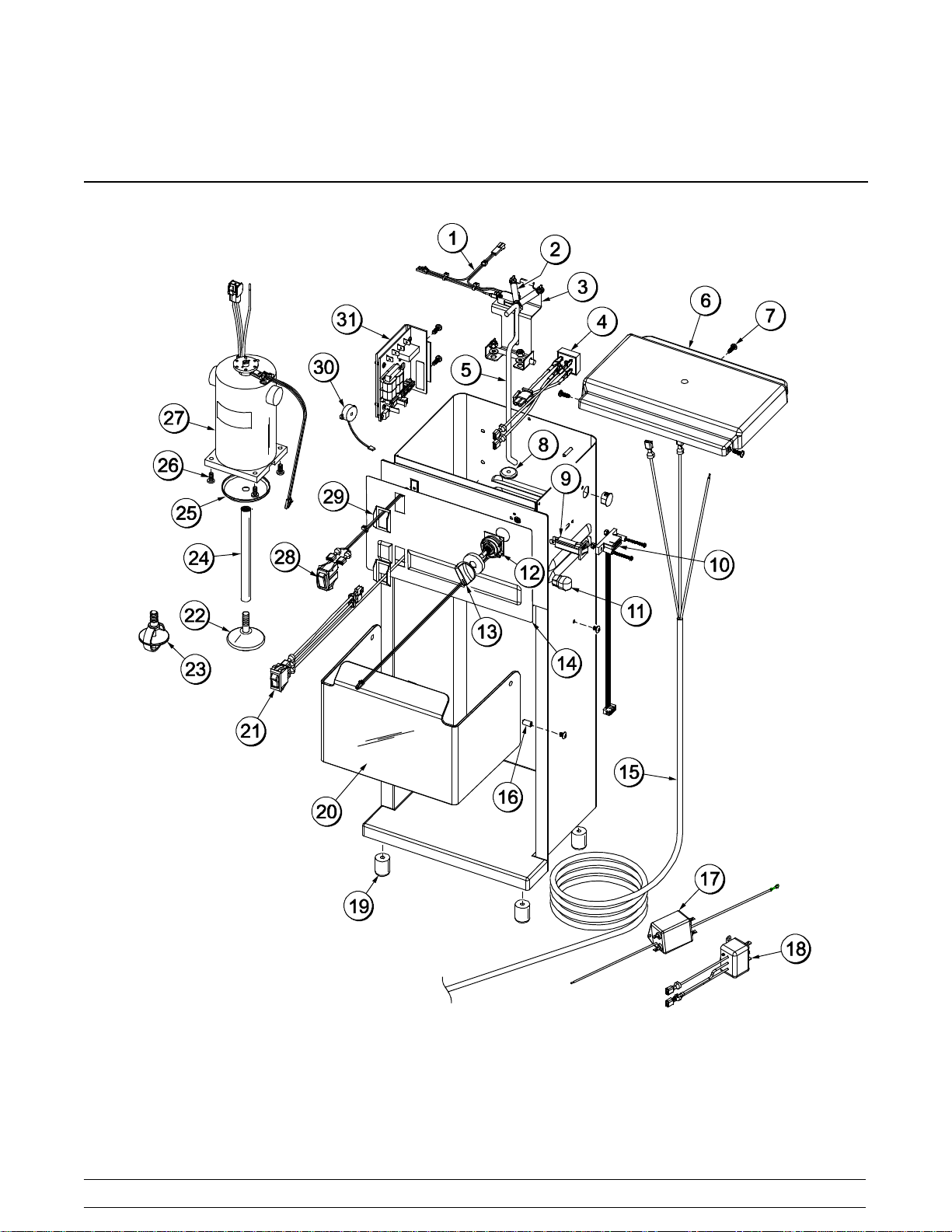
Section 4 Operator Parts Identification
BC12
Figure 1
6
Model BC12Operator Parts Identification
Page 11

BC12 Parts Identification
ITEM DESCRIPTION PART NO.
1 SWITCH-ROD-SNAP ACTION 067650
2 SPRING-SWITCH ROD*BC12* 067648
3 ROD A.-SWITCH*BC12* 067647
4 BRIDGE-RECTIFIERW/WIRES 067646
5 ROD-SWITCH*BC12* 067649
6 CAP-MIXER 051484
7 SCREW-MIXER-RETAINERCAP 051487
8 SEAL-SWITCH ROD*BC12* 067651
9 BREAKER-CIRCUIT-MIXER-2A 067637
10 CABLE-MEMORY*BC12* 067654
11 RELIEF-STRAIN-MIXER-R ANGL 067636
12 SWITCH-SELECTOR-CONTROL 067634
13 KNOB-CONTROL-SPEED*BC12* 067635
14 DECAL-DEC-RAZZLE*BC12* 067645
15 CORD-POWER-120V*BC12* 067640
16 PIN-PIVOT-SPLASH GUARD
W/SCREWS
17 FILTER-EMI*BC12* 067655
18 SUPPRESSOR-SURGE*BC12* 067656
067642
ITEM DESCRIPTION PART NO.
19 FOOT A.-MIXER-PLUGGED 051500
20 GUARD-SPLASH*BC12* 067638
21 SWITCH-ROCKER-LIGHTED 067643-40
22 AGITATOR-CONE*BC10*BC12* 067549
23 AGITATOR-MIXER-PERM
(GLOBE) (OPTIONAL)
24 SHAFT-AGITATOR-EXTENSION 051495
25 SLINGER-MIXER 051494
26 SCREW-MIXER-MOTORMTG 051493
27 MOTOR A.-ADVANCE*BC12* 067632-40
28 SWITCH-PUSHBUTTON-MOM 054699
29 GUARD-SWITCH*BC12* 067652
30 ALARM-AUDIBLE
W/MOUNT*BC12*
31 BOARD-CONTROL-UNIVERSAL 067633
* ADAPTOR-PLUG-JAPAN*BC12* 067657
* KIT-PROGRAM
SOFTWARE*BC12*
* KIT-PROGRAMCHIP*BC12* 067658
*NOT SHOWN
051497
067660
067659
100921
Model BC12 Operator Parts Identification
7
Page 12
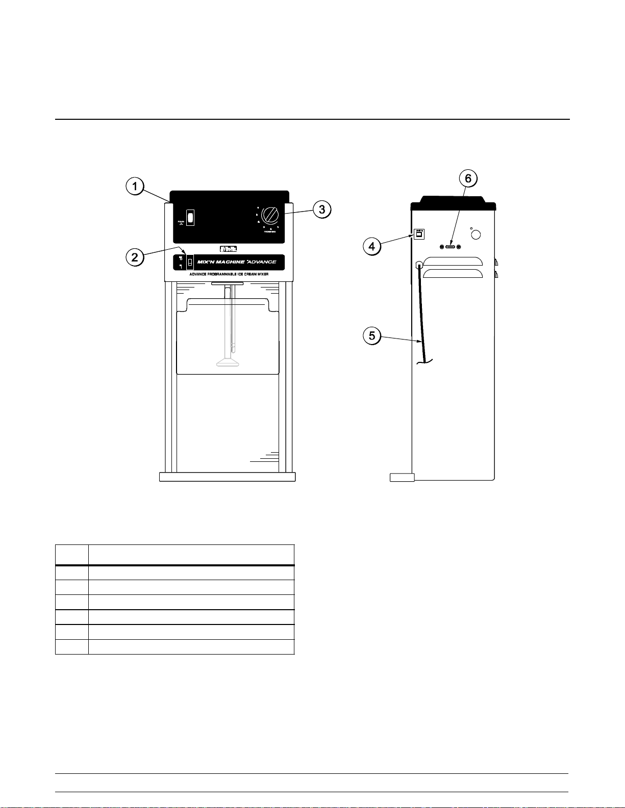
Section 5 Important: To the Operator
BC12
ITEM DESCRIPTION
1 PULSE/RINSE SWITCH
2 POWER SWITCH
3 PROGRAM DIAL
4 RESET SWITCH
5 POWER CORD
6 PROGRAMMING PORT
091020
Figure 2
8
The BC12 blender is pre-programmed with one
blending option and a pulse switch.
Model BC12Important: To the Operator
Page 13
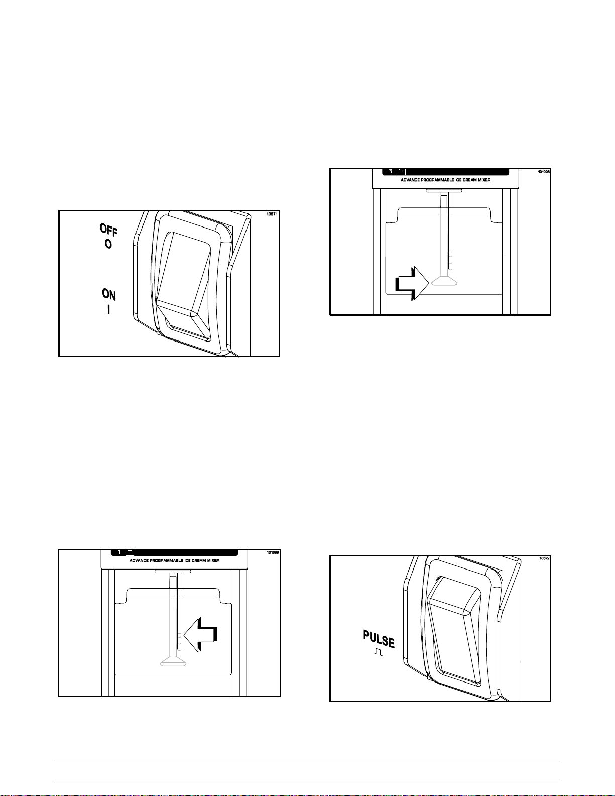
ON/OFF Power Switch
The power switch is located on the front of the
machine. The power switch controls the power to
the machine. The switch illuminates when placed in
the ON position. Shut the power switch off at night
and whenever the machine will be left unattended.
Figure 3
Agitator
When the switch rod (actuator) is pushed, the
agitator spins and mixes the product and other
ingredients.
Figure 5
The agitator is manufactured from FDA and NSF
approved, food safe material.
Note: The agitator and shaft must be cleaned
between servings as product carryover will
occur. (See page 15.)
Switch Rod (Actuator)
The switch rod (actuator) starts the agitator and
begins a blending cycle. Push the switch rod to
activate a program setting. The machine shuts off
automatically at the end of the program setting.
Figure 4
Pulse/Rinse Switch
The pulse/rinse switch starts the agitator and can be
used to quickly refresh product or rinse the agitator
between servings. Press and hold the switch to
activate the agitator. The agitator will stop as soon
as the pulse switch is released.
Figure 6
Model BC12 Important: To the Operator
9
Page 14

Program Dial
Splash Guard
The program dial allows the operator to select a
number of pre-programmed settings. The machine
will shut off automatically at the end of the program.
Figure 7
Reset Switch
The reset switch is located above the power switch
on the front panel. The reset switch protects the
motor from an overload condition. If an overload
occurs, the reset mechanism will trip. To properly
reset the unit, wait a short period of time to allow the
motor to cool. Press the reset switch and resume
operation.
The splash guard catches product thrown from the
agitator and shields the operator during mixing.
Figure 9
Figure 8
10
Model BC12Important: To the Operator
Page 15
Section 6 Operating Procedures
Mixing Instructions
Make sure your hands are clean and sanitized
before performing these steps.
Step 1
Fill a serving cup with product (dairy slush or neutral
slush).
Figure 10
Step 2
Add “mix-in” ingredients such as liquid flavoring,
candy, cookies, fruit, or other condiments.
Step 4
Select the desired setting on the dial.
Figure 12
Step 5
Holding the cup securely from the side, reach under
the splash guard. Move the cup under the agitator
and lift up so the agitator touches the bottom of the
cup.
Step 3
Place the power switch in the ON position.
Figure 11
Model BC12 Operating Procedures
11
Figure 13
091020
Page 16

Step 6
While holding the cup securely in your hand, use
your fingers to push the switch rod (actuator),
located behind the agitator, to activate a
programmed blending cycle.
Figure 14
Notes:
S If the cup is hard to hold, either move the
agitator into the mix more slowly or start
with softer product. Do not continue to
operate the mixer if the cup is too hard to
hold.
S The agitator is designed to reduce the
possibility of damage when contacting a
paper cup. However, the agitator should not
be forced or held solidly against the side or
bottom of the cup. The hard product agitator
is specially designed to mix the product
aggressively and thoroughly, so use a cup
holder or a sturdy cup to prevent the agitator
from going through the side of the cup.
Step 8
Swirl the cup around the agitator to produce a
pleasing product appearance and to avoid leaving a
hole in the center of the mixture. Before removing
the cup, allow the excess mixture to be thrown off
the agitator and caught by the cup.
Step 7
Using a swirling motion, gradually move the cup up
and down around the spinning agitator and
completely around all sides of the cup. (If the
product is hard, this should be done slowly.)
The agitator will do some chipping and breaking of
the solids. However, it is not intended to completely
pulverize ingredients. Solid chunks are expected to
be evident in the finished product.
The machine shuts off automatically at the end of
the programmed cycle. When the program is within
4 seconds of completion, a tone will sound, so
preparation can begin to remove the cup from the
agitator. The tone gets progressively faster to
indicate that the program cycle is almost complete
and the machine will shut off. This allows the
operator the opportunity to spin off excess product
from the agitator.
Step 9
Place the power switch in the OFF position when the
machine is not in use.
100921
Figure 15
12
Figure 16
Model BC12Operating Procedures
Page 17

Pulse Switch Operation
Make sure your hands are clean and sanitized
before performing these steps.
Step 1
Place the power switch in the ON position.
Figure 17
Step 3
Press the pulse switch to start the agitator.
Figure 19
Step 4
With a swirling motion, gradually move the cup up
and down over the spinning agitator and completely
around all sides of the cup. Swirl the cup around the
agitator to produce a pleasing product appearance
and to avoid leaving a hole in the center of the
mixture.
Step 2
Hold the cup under the agitator and lift up, so the
agitator touches the bottom of the cup.
Figure 18
Figure 20
Step 5
Before removing the cup, allow excess mixture to be
thrown off the agitator and be caught by the cup or
lid/collar.
091020
Model BC12 Operating Procedures
13
Page 18

Step 6
Release the switch to stop the agitator.
Figure 21
Daily Cleaning
Step 3
Remove the splash guard by squeezing the sides
until it is clear of the top pivot pins and then pulling it
out. Take it to the sink for cleaning and sanitizing.
Figure 22
Step 4
Wash the splash guard in the approved cleaning
solution.
Taylor recommends daily cleaning and
sanitizing.
ALWAYS FOLLOW LOCAL HEALTH CODES
Step 1
Prepare a sink with an approved cleaning solution
(examples: Kay-5r or Stera-Sheenr). USE HOT
WATER (110_F/43_C) AND FOLLOW THE
MANUFACTURER'S SPECIFICATIONS. Do not
use a solution that contains ammonia and avoid
placing components in a dishwasher.
Step 2
Disconnect power from the wall
receptacle before performing the following
steps. Failure to comply may result in electrical
shock.
Step 5
Wipe clean all stainless steel surfaces with an
approved, non-abrasive commercial cleaner. This
includes the mixer, dispenser, and organizer
surfaces.
Step 6
Clean sticky switches with a clean cloth, dampened
with cleaning solution. Clean around the edges of
the switch paddles until they function freely. Work
the switches back and forth a few times to loosen
any dried residue under the switch. Dry the switches
withasoftcottoncloth.
Note: Leaving the switches sticky will damage or
burn them out.
WARNING: Do not spray water or other
liquid around the motor chamber. Do not use
excess liquid around the switches, motor protector,
power cords, or cord entry hole. Make certain all
areas in and around the motor are dry before
connecting power to the wall receptacle. Failure to
comply may cause equipment damage or
personal injury due to electric shock.
14
Model BC12Operating Procedures
Page 19
Sanitizing
Taylor recommends daily cleaning and
sanitizing.
Step 1
Prepare a sink with an approved sanitizing solution
(examples: Kay-5r or Stera-Sheenr). USE HOT
WATER (110_F/43_C) AND FOLLOW THE
MANUFACTURER'S SPECIFICATIONS.
Step 3
Submerge the agitator in the cleaning solution, all
the way to the bottom of the motor chamber. Place
the power switch in the ON position. Allow the
agitator to run for about 15 seconds. Repeat this
step several times. Make certain all portions of the
agitator and shaft have been submerged in the
cleaning solution.
Step 2
Repeat Steps 4 - 5 of the cleaning procedure, using
the sanitizing solution.
Step 3
Install the splash guard by squeezing the sides and
placing it onto the top pivot pins.
Step 4
Repeat the sanitizing procedures at the start of the
day.
ALWAYS FOLLOW LOCAL HEALTH CODES
Agitator Cleaning and Sanitizing
Step 1
Remove the splash guard by squeezing the sides
until it clears the top pivot pins and then pull the
guard out.
Step 2
Prepare a durable container with an approved cleaning solution (example: Kay-5r or Stera-Sheenr).
USE HOT WATER (110_F/43_C) AND FOLLOW
THE MANUFACTURER'S SPECIFICATIONS. Do
not use a solution that contains ammonia.
Note: The container must be deep enough to
submerge the entire agitator and shaft.
WARNING: Never try to wipe clean the
agitator while it is active. Failure to follow these
instructions can lead to severe personal injury from
hazardous moving parts, or damage to the unit.
Step 4
Repeat Step 3, using cool, clean water.
Step 5
Prepare a durable container with an approved sanitizing solution (example: Kay-5r or Stera-Sheenr).
USE HOT WATER (110_F/43_C) AND FOLLOW
THE MANUFACTURER'S SPECIFICATIONS. Do
not use a solution that contains ammonia.
Step 6
Repeat Step 3, using the sanitizing solution. Allow
the agitator to run for a minimum of two minutes.
Step 7
Re-install the splash guard by squeezing the sides
and placing it onto the top pivot pins.
Step 8
Repeat the sanitizing procedures at the start of the
day.
ALWAYS FOLLOW LOCAL HEALTH CODES
100921
Model BC12 Operating Procedures
15
Page 20

Section 7 Parts List
REMARKS
CLASS
QTY. WARR.
NUMBER
DESCRIPTION PART
+SCREW-MIXER-RETAINERCAP 051487 3 000
+ADAPTOR-PLUG-JAPAN*BC12* 067657 * 103 *OPTIONAL
ALARM-AUDIBLE W/MOUNT *BC12* 067660 1 103
AGITATOR-CONE*BC10*BC12* 067549 1 000 DISC
AGITATOR-MIXER-PERMSOFT SERVE (GLOBE) 051497 * 000 OPTIONAL
BOARD-CONTROL-UNIVERSAL*B 067633 1 103
BREAKER-CIRCUIT-MIXER-2 A 067637 1 103
BRIDGE-RECTIFIERW/WIRES* 067646 1 103
CABLE-MEMORY*BC12* 067654 1 103
CAP-MIXER 051484 1 103 HOOD
CORD-POWER-120V*BC12* 067640 1 103
FILTER-EMI*BC12* 067655 1 000
FOOT A.-MIXER-PLUGGED 051500 4 000
GUARD-SPLASH*BC12* 067638 1 000 CLEAR PLASTIC
KIT-PROGRAM SOFTWARE*BC12* 067659 1 000
KIT-PROGRAM CHIP*BC12* 067658 1 000
LIGHT-INDICATOR-LED*BC12* 067644 * 000 *USED PRIOR TO 067660 ALARM-AUDIBLE
100921
Parts List Model BC12
16
MOTOR A.-ADVANCE*BC12* 067632-12 1 103 115V
MOTOR A.-ADVANCE*BC12* 067632-40 1 103 220-240V
+SCREW-MIXER-MOTOR MOUNTING 051493 4 000
+GUARD-SWITCH*BC12* 067652 1 000
PIN-PIVOT-SPLASHGUARD*BC 067642 1 000 SET 4-PINS & 4-SCREWS
RELIEF-STRAIN-MIXER-R ANG 067636 1 000
SHAFT-AGITATOR-EXTENSION- 051495 1 000
SLINGER-MIXER 051494 1 000 BETWEEN SHAFT & MOTOR
SUPPRESSOR-SURGE*BC12* 067656 1 103
SWITCH-PUSHBUTTON-MOM 054699 1 000
SWITCH-ROCKER-LIGHTED*BC12* 067643-12 1 103 115V
SWITCH-ROCKER-LIGHTED*BC1 067643-40 1 103 220-240V
SWITCH-ROD-SNAP ACTION*BC 067650 1 103
Page 21

CLASS
QTY.PART
NUMBER
DESCRIPTION REMARKSWARR.
+ROD A.-SWITCH*BC12* 067647 1 103
Model BC12
+ROD-SWITCH*BC12* 067649 1 000
+SEAL-SWITCH ROD*BC12* 067651 1 000
+SPRING-SWITCH ROD*BC12* 067648 1 000
SWITCH-SELECTOR-CONTROL*B 067634 1 103
KNOB-CONTROL-SPEED*BC12* 067635 1 103
17
100921
Parts List
Page 22
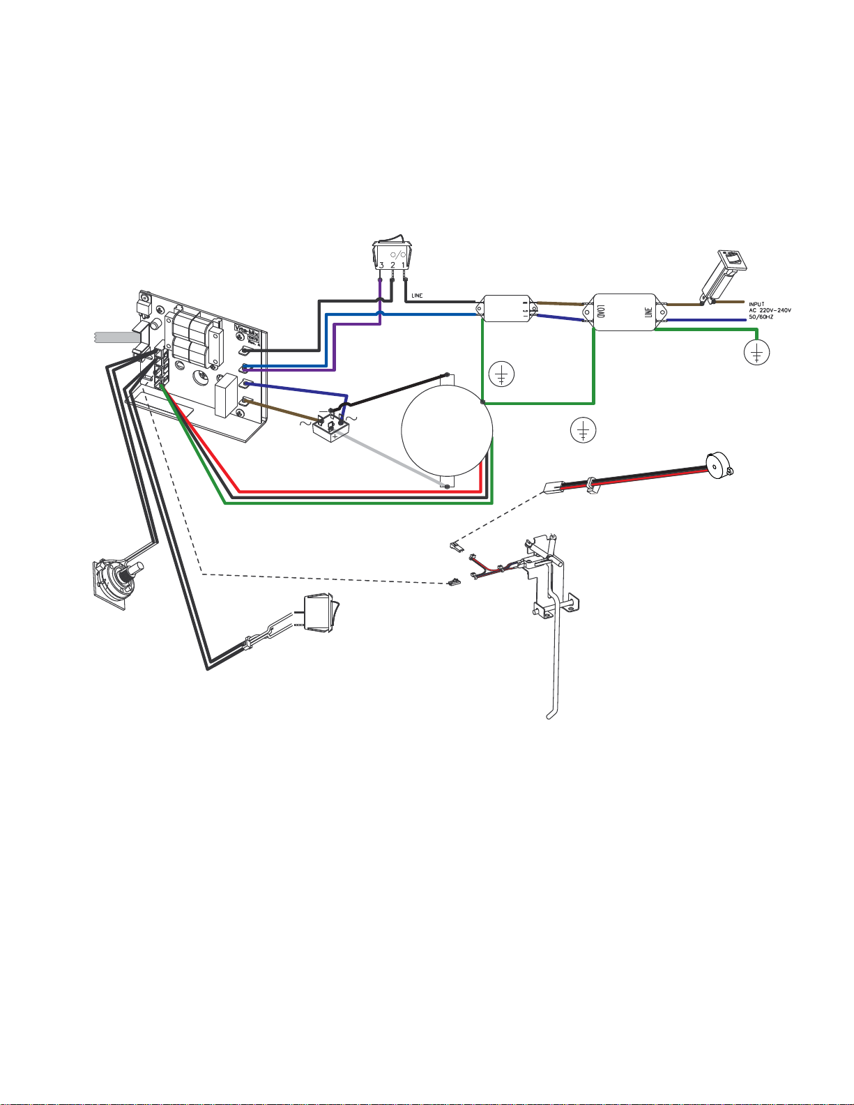
Wiring Diagram
y
TO
PROGRAMMING
PORT
LIT SWITCH
SURGE
SUPPRESSOR
GROUND
RFI
FILTER
2A
CIRCUIT
BREAKER
GROUND
PROGRAM
SELECTOR
SWITCH
(SAFETY
LOW
VOLTAGE)
HALL EFFECT SENSOR -
NON-CONTACT
PULSE
SWITCH
(SAFETY
LOW
VOLTAGE)
DC PM MOTOR
220V-240V
50/60 HZ
PM - DC
GROUND
Model BC12
Wiring Diagram
For Training Purposes Onl
2009hz0528
INITIATE
SWITCH
(SAFETY
LOW
VOLTAGE)
 Loading...