

Page 1

OPERATOR'S
MANUAL
Model BC10/BW11
Razzle Blenders
Original Operating Instructions
052544-M 2/1/01 (Original Publication)
(Updated 9/15/14)
Page 2

Complete this page for quick reference when service is required:
Taylor Distributor:
Address:
Phone:
Service:
Parts:
Date of Installation:
Information found on the data label:
Model Number:
Serial Number:
Electrical Specs: Voltage Cycle
Phase
Maximum Fuse Size: A
Minimum Wire Ampacity: A
E 2001 Carrier Commercial Refrigeration, Inc.
052544- M
Any unauthorized reproduction, disclosure, or distribution of copies by any person of any portion of this work may be
a violation of Copyright Law of the United States of America and other countries, could result in the awarding of Statutory
Damages of up to $250,000 (17 USC 504) for infringement, and may result in further civil and criminal penalties.
All rights reserved.
Taylor Company
a division of Carrier Commercial Refrigeration, Inc.
750 N. Blackhawk Blvd.
Rockton, IL 61072
Page 3

Table of Contents
Section 1 To the Installer 1............................................
Installer Safety 1........................................................
Site Preparation 1.......................................................
Electrical Connections 2.................................................
Foot Pedal Instructions 2................................................
Section 2 To the Operator 3...........................................
Section 3 Safety 4....................................................
Section 4 Operator Parts Ident ificatio n 6...............................
BC10 - Standard Unit 6.................................................
BC10 - Unit Equipped With Timer 8.......................................
BW11 - Standard Unit 10.................................................
Accessories 12..........................................................
Optional Dispensers 13...................................................
Optional Large Candy Dispenser Canister Assembly (X53638- 1) 18...........
Optional Small Candy Dispenser Canister Assembly (X53638- 2) 19............
Section 5 Important: To the Operator 20.................................
On/Off Switch 20.........................................................
Start Switch (Timer Equipped Units, Only) 20................................
Foot Pedal 20...........................................................
Reset Switch 20.........................................................
Splash Guard 21.........................................................
Motor 21................................................................
Agitators 21.............................................................
Candy Dispenser Canisters 22.............................................
Table of Contents Models BC10/BW11
Page 4

Table of Contents - Page 2
Section 6 Operating Procedures 23.....................................
Mixing Instructions 23....................................................
Daily Cleaning 25........................................................
Sanitizing 26............................................................
Section 7 Limited Warranty on Equipment 27............................
Wiring Diagram 29.......................................................
Note: Continuing research results in steady improvements; therefore, information
in this manual is subject to change without notice.
Note: Only instructions originating from the factory or its authorized translation
representative(s) are con sid ered to be th e original set of in struction s.
E 2001 Carrier Commercial Refrigeration, Inc. (Original Publication)
Updated September, 2014
052544- M
Any unauthorized reproduction, disclosure, or distribution of copies by any person of any portion of this work
may be a violation of Copyright Law of the United States of America and other countries, could result in the
awarding of Statutory Damages of up to $250,000 (17 USC 504) for infringement, and may result in further
civil and criminal penalties.
All rights reserved.
Taylor Company
a division of Carrier Commercial Refrigeration, Inc.
750 N. Blackhawk Blvd.
Rockton, IL 61072
Models BC10/BW11 Table of Contents
Page 5
Section 1 To the Installer
The following information has been included in the
manual as safety and regulatory guidelines. For
complete installation instructions, please see the
Installation Checklist.
Installer Safety
In all areas of the world, equipment should be
installed in accordance with existing local codes.
Please contact your local authorities if you have any
questions.
Care should be taken to ensure that all basic safety
practices are followed during the installation and
servicing activities related to the installation and
service of Taylor equipment.
S Only authorized Taylor service personnel
should perform installation and repairs on the
equipment.
S Authorized service personnel must ensure
that the proper PPE is available and worn
when required during installation and service.
S Authorized service personnel must remove all
metal jewelry , rings, and watches before
working on electrical equipment.
Site Preparation
Review the area where the unit will be installed before
uncrating the unit. Make sure that all possible hazards
to the user and the equipment have been addressed.
For IndoorUse Only: This unit is designed to operate
indoors, under normal ambient temperatures of
70_-75_F(21_-24_C). The unit has successfully per-
formed in high ambient temperatures of 104_(40_C) at
reduced capacities.
This unit must NOT be installed in an area
where a water jet or hose can be used. NEVER use a
water jet or hose to rinse or clean the unit. Failure to
follow this instruction may result in electrocution.
This unit must be installed on a level surface
to avoid the hazard of tipping. Extreme care should be
taken in moving this equipment for any reason. Failure
to comply may result in personal injury or equipment
damage.
Uncrate the unit and inspect it for damage. Report any
damage to your Taylor Distributor.
The main power supply(s) to the machine
must be disconnected prior to performing any repairs.
Failure to follow this instruction may result in personal
injury or death from electrical shock or hazardous
moving parts as well as poor performance or damage
to the equipment.
Note:Allrepairsmustbeperformedbyan
authorized Taylor Service Technician.
This unit has many sharp edges that can
cause severe injuries.
This piece of equipment is made in the USA and has
USA sizes of hardware. All metric conversions are
approximate and vary in size.
140106
Models BC10/BW11 To the Installer
1
Page 6
Electrical Connections
In the United States, this equipment is intended to be
installed in accordance with the National Electrical
Code (NEC), ANSI/NFPA 70- 1987. The purpose of
the NEC code is the practical safeguarding of persons
and property from hazards arising from the use of
electricity. This code contains provisions considered
necessary for safety. Compliance therewith and
proper maintenance will result in an installation
essentially free from hazard!
In all other areas of the world, equipment should be
installed in accordance with the existing local codes.
Please contact your local authorities.
FOLLOW YOUR LOCAL ELECTRICAL CODES!
Each unit requires one power supply for each data
label on the unit. Check the data label(s) on the unit for
branch circuit overcurrent protection or fuse, circuit
ampacity, and other electrical specifications. Refer to
the wiring diagram provided inside of the electrical box
for proper power connections.
S Stationary appliances which are not equipped
with a power cord and a plug or other device
to disconnect the appliance from the power
source must have an all- pole disconnecting
device with a contact gap of at least 3 mm
installed in the external installation.
S Appliances that are permanently connected to
fixed wiring and for which leakage currents
may exceed 10 mA, particularly when
disconnected or not used for long periods, or
during initial installation, shall have protective
devices such as a GFI, to protect against the
leakage of current, installed by the authorized
personnel to the local codes.
S Supply cords used with this unit shall be
oil-resistant, sheathed flexible cable not
lighter than ordinary polychloroprene or other
equivalent synthetic elastomer-sheathed cord
(Code designation 60245 IEC 57) installed
with the proper cord anchorage to relieve
conductors from strain, including twisting, at
the terminals and protect the insulation of the
conductors from abrasion.
If the supply cord is damaged, it must be
replaced by the manufacturer, its service
agent, or similarly qualified person, in order to
avoid a hazard.
CAUTION: THIS EQUIPMENT MUST BE
PROPERLY GROUNDED! FAILURE TO DO SO
CAN RESULT IN SEVERE PERSONAL INJURY
FROM ELECT RI CAL SHOCK!
This equipment is provided with a grounding lug
that is to be properly attached to the rear of the frame
by the authorized installer. The installation location is
marked by the equipotential bonding symbol (5021 of
IEC 60417- 1) on the removable panel and the frame.
130419
Foot Pedal Instructions
The foot pedal is an optional accessory on units not
equipped with a timer. To use the foot pedal to control
the mixer, connect the foot pedal to a grounded wall
outlet. Plug the mixer cord into the back of the foot
pedal plug. In this mode, both the On/Off switch and
the foot pedal must be activated. Leave the On/Off
switch in the ON position when you wish to use the foot
control. Make sure the foot control is kept where it will
not be activated accidentally . The foot guard is an
additional design feature which helps prevent
accidental use of the foot pedal.
2
Models BC10/BW11To the Installer
Page 7

Section 2 To the Operator
The mixer you have purchased has been carefully
engineered and manufactured to give you dependable
operation. Mixing various candies, cookies, fruits,
nuts, liquid flavors, and other food items into ice cream
or frozen yogurt has made unlimited flavor
combinations and product textures available.
The development of counter and wall mount mixers
have made this unlimited resource available to even
very small retail outlets and to those facilities where
counter space is limited.
The mixer, when properly operated and cared for, will
produce a consistent, quality product. Like all
mechanical products, it will require cleaning and
maintenance. A minimum amount of care and
attention is necessary if the operating procedures
outlined in this manual are followed closely .
This Operator’s Manual should be read
before operating or performing any maintenance on
your equipment. In the event that you should require
technical assistance, please contact your local
authorized Taylor Distributor.
Note: Your Taylor warranty is valid only if the parts are
authorized Taylor parts, purchased from the local
authorized Taylor Distributor, and only if all required
service work is provided by an authorized Taylor
service technician. Taylor reserves the right to deny
warranty claims on units or parts if non- Taylor
approved parts or incorrect refrigerant were installed
in the unit, system modifications were performed
beyond factory recommendations, or it is determined
that the failure was caused by abuse, misuse, neglect,
or failure to follow all operating instructions. For full
details of your Taylor Warranty, please see the Limited
Warranty section in this manual.
Note: Constant research results in steady
improvements; therefore, information in this
manual is subject to change without notice.
NSF approvals of the Models BC10 and BW11 were
obtained by the Vita- Mix Corporation, 8615 Usher
Road, Cleveland, Ohio 44138.
If the crossed out wheeled bin symbol is
affixed to this product, it signifies that this product is
compliant with the EU Directive as well as other similar
legislation in effect after August 13, 2005. Therefore,
it must be collected separately after its use is
completed, and cannot be disposed as unsorted
municipal waste.
The user is responsible for returning the product to the
appropriate collection facility, as specified by your local
code. For additional information regarding applicable
local laws, please contact the municipal facility and/or
local distributor.
140106
Models BC10/BW11 To the Operator
3
Page 8
Section 3 Safety
Taylor is concerned about the safety of the operator
when he or she comes in contact with the blender and
its parts. Taylor has gone to extreme efforts to provide
built- in safety features to protect both you and the
service technician. As an example, warning labels
have been attached to the unit to further point out
safety precautions to the operator.
IMPORTANT - Failure to adh ere to the
following safety precautions may result in severe
personal injury or death. Failure to comply with
these warnings may damage the machine and its
components. Component damage will result in
part replacement expense and service repair
expense. SAVE THESE INSTRUCTIONS FOR
FUTURE REFERENCE
unit. Failure to follow these instructions may result in
serious electrical shock.
DO NOT use a water jet to clean or rinse the
S DO NOT operate the unit unless it is properly
grounded.
S DO NOT operate the unit with larger fuses
than specified on the data label.
S All repairs must be performed by an
authorized Taylor service technician.
To Operate Safely:
DO NOT operate the unit without reading
this operator’s manual. Failure to follow this instruction
may result in equipment damage, poor performance,
health hazards, or personal injury.
This appliance is to be used only by trained
personnel. It is not intended for use by children or
people with reduced physical, sensory, or mental
capabilities, or lack of experience and knowledge,
unless given supervision or instruction concerning the
use of the appliance by a person responsible for their
safety. Children should be supervised to ensure that
they do not play with the appliance.
This unit is provided with an equipotential
grounding lug that is to be properly attached to the rear
of the frame by the authorized installer. The installation
location is marked by the equipotential bonding
symbol (5021 of IEC 60417-1) on both the removable
panel and the frame.
S The main power supplies to machine must be
disconnected prior to performing repairs.
S Cord Connected Units: Only Taylor authorized
service technicians or licensed electricians
may install a plug or replacement cord on
these units.
S DO NOT operate this appliance if the power
cord is damaged.
S DO NOT use this appliance outdoors.
S Stationary appliances which are not equipped
with a power cord and a plug or another device
to disconnect the appliance from the power
source must have an all-pole disconnecting
device with a contact gap of at least 3 mm
installed in the external installation.
S Appliances that are permanently connected to
fixed wiring and for which leakage currents
may exceed 10 mA, particularly when
disconnected or not used for long periods, or
during initial installation, shall have protective
devices such as a GFI, to protect against the
leakage of current, installed by the authorized
personnel to the local codes.
130419
4
Models BC10/BW11Safety
Page 9
S Supply cords used with this unit shall be
oil-resistant, sheathed flexible cable not
lighter than ordinary polychloroprene or other
equivalent synthetic elastomer- sheathed
cord (Code designation 60245 IEC 57)
installed with the proper cord anchorage to
relieve conductors from strain, including
twisting, at the terminals and protect the
insulation of the conductors from abrasion.
If the supply cord is damaged, it must be
replaced by the manufacturer, its service
agent, or similarly qualified person, in order to
avoid a hazard.
Failure to follow these instructions may result in
electrocution. Contact your local authorized Taylor
Distributor for service.
S DO NOT allow children or untrained personnel
to operate this machine.
S DO NOT operate the unit unless all service
panels and access doors are restrained with
screws.
S AVOID contact with the agitator shaft and
other moving parts.
S Make sure the splash guard is installed prior
to operating the appliance.
S DO NOT disassemble or install parts unless
the On/Off switch is in the OFF position.
S If unit is equipped with a foot pedal, always
use the foot pedal guard. Avoid accidental use
of the foot pedal. When using the foot pedal,
make sure the appliance is located where
accidental contact with the pedal is not likely .
When the mixer is not in use, place the front
switch in the OFF position to avoid accidental
use of the pedal.
Failure to follow these instructions may result in severe
personal injury from hazardous moving parts.
DO NOT operate this appliance if it
malfunctions or is damaged in any way. Failure to
follow this instruction may result in injury or component
damage.
Cleaning and sanitizing schedules are
governed by your Federal, State, or local regulatory
agencies and must be followed accordingly. Please
refer to the cleaning section of this manual for the
proper procedure to clean this unit.
DO NOT use attachments not recommended
or sold by Taylor. Doing so may cause fire, electric
shock, injury, or equipment damage.
Make sure the mixer is sitting or mounted
solidly on a sturdy surface during operation. Failure to
comply may result in injury or equipment damage.
WARNING!
Some consumers are highly allergic to
peanuts, peanut oil, and peanut dust. In
some severe cases, peanut allergy
reactions can cause death. When
blending product with peanuts, make
sure excess product is cleaned from the
agitator shaft to eliminate the fear of
product carryover.
NOISE LEVEL: Airborne noise emission does not
DO NOT allow the power cord to hang over
the edge of the counter or touch hot surfaces. Failure
to comply may result in an electrical fire.
Models BC10/BW11 Safety
exceed 78 dB(A) when measured at a distance of 1.0
meter from the surface of the machine and at a height
of 1.6 meters from the floor.
130515
5
Page 10
Section 4 Operator Parts Identification
BC10 - Standard Unit
130524
6
Models BC10/BW11Operator Parts Identification
Page 11

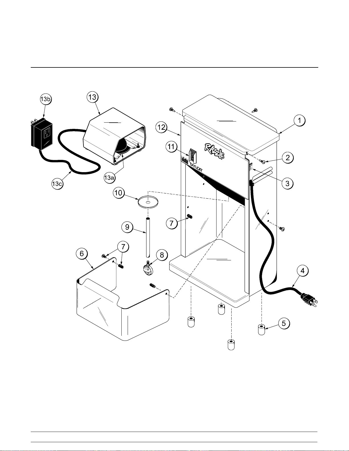
BC10 Standard Unit - Exploded View Parts Identification
ITEM DESCRIPTION PART NO.
1 CAP- MIXER 051484
2 SCREW- MIXER- RETAINER
CAP
BREAKER- CIRCUIT- MIXER3A- 120V
3
BREAKER- CIRCUIT- MIXER- 5A
- 220/240V
4 CORD- MIXER- 18/3
GROUNDED W/PLUG
5 FOOT A.- MIXER- PLUGGED-
PKG OF 4
6 GUARD - SPLASH- MIXER 051499
7 PIVOT PIN&SCREW*PKG OF 4* 051507
8 AGITATOR- MIXER- PERM SOFT 051497
9 SHAFT- MIXER- AGITATOR- EXT
- PERMANENT
051487
051489
051490
051491
051500
051495
ITEM DESCRIPTION PART NO.
10 SLINGER- MIXER 051494
11 SWITCH- ROCKER- MIXER 051488
12 LABEL- MIXER- COUNTER-
RAZZLE
PEDAL- FOOT - MIXER- 120V 052451
13
PEDAL- FOOT - MIXER- 220V 053192
13a TRANSMITTER FOOT PEDAL 052451- 1
CONTROLLER- FOOT PEDAL115V
13b
SWITCH- PRESSURE- FOOT
PEDAL- 220
13c TUBE - AIR - FOOT PEDAL 052451- 3
052250
052451- 2
053192- 1
130524
Models BC10/BW11 Operator Parts Identification
7
Page 12

BC10 - Unit Equipped With Timer
130529
8
Models BC10/BW11Operator Parts Identification
Page 13

BC10 Unit Equipped With Timer - Exploded View Parts Identification
ITEM DESCRIPTION PART NO.
1 CAP- MIXER 051484
2 SCREW- MIXER- RETAINER
CAP
3 BREAKER- CIRCUIT- MIXER- 5A
220/240V
4 FOOT A.- MIXER- PLUGGED-
PKG OF 4
5 GUARD- SPLASH- MIXER 051499
6 PIVOT PIN&SCREW*PKG OF 4 051507
051487
051490
051500
ITEM DESCRIPTION PART NO.
7 SHAFT- DRIVEN SPINNER-
MIXER
8 SLINGER- MIXER 051494
9 SWITCH- ROCKER- LIGHTED 067643- 40
10 LABEL- MIXER- COUNTER-
RAZZLE
11 SWITCH- PUSHBUTTON-
MOMENTARY (START BUTTON)
051436
052250
054699
130524
Models BC10/BW11 Operator Parts Identification
9
Page 14

BW11 - Standard Unit
130524
10
Models BC10/BW11Operator Parts Identification
Page 15

BW11 Standard Unit - Exploded View Parts Identification
ITEM DESCRIPTION PART NO.
1 COVER- MIXER- TOP WALL MT 051516
2 LABEL- MIXER- WALL- FRONT/
SIDE - 3
BREAKER- CIRCUIT- MIXER- 3A
120V
3
BREAKER- CIRCUIT- MIXER- 5A
220/240V
4 SWITCH- ROCKER- MIXER 051488
5 BUSHING- MIXER- TRAVEL ROD 051522
6 GUARD- SPLASH- MIXER- CUP-
WALL MOUNT
7 SLINGER- MIXER 051494
8 SHAFT- MIXER- AGITATOR - EXT
- WALL MOUNT
052251
051489
051490
051518
051520
ITEM DESCRIPTION PART NO.
9 AGITATOR- MIXER- PERM SOFT
SERVE
10 KIT- DRIP PAN- BW11 052429
PEDAL- FOOT - MIXER- 120V 052451
11
PEDAL- FOOT - MIXER- 220V 053192
11a TRANSMITTER- FOOT PEDAL 052451- 1
CONTROLLER- FOOT
PEDAL- 115V
11b
SWITCH- PRESSURE- FOOT
PEDAL- 220V
11c TUBE- AIR- FOOT PEDAL 052451 - 3
12 CORD- MIXER- 18/3
GROUNDED W/PLUG
051497
052451- 2
053192- 1
051491
139524
Models BC10/BW11 Operator Parts Identification
11
Page 16

Accessories
ITEM DESCRIPTION PART NO.
1 ORGANIZER A.- CUP/LID X52080
1a INSERT- SPOON BIN 052113
1b COLUMN- LID DISPENSER 052084
1c SCREW- 1/4 X 1 HEX HEAD 052139
CUP 12 OZ RAZZLE 1000/CS 051967
2
CUP 16 OZ RAZZLE 1000/CS 051968
3 LID RAZZLE CLEAR DOME
1200/CS
051969
131010
ITEM DESCRIPTION PART NO.
4 COLLAR- PLASTIC 051750
5 KIT- DRIP PAN 052429
6a SHAFT- DRIVEN SPOON
MIXER
6b AGITATOR - MIXER-
PERMANENT SOFT SERVE
*6c AGITATOR- MIXER-
PERMANENT HARD SERVE
*NOT SHOWN
12
Models BC10/BW11Operator Parts Identification
051436
051497
051498
Page 17

Optional Dispensers
X52037- 1
Item Description Part No.
Dispenser A.-2 Large - 2 Small X52037-1
1 Bracket A.-Wall Mount X52035
2 Canister A.-Large (2) X53638-1
3 Canister A.-Small (2) X53638-2
4 Kit A.-Dispenser-WallMount X52039
4a Screw-10-24 x 2 Sltd Pan Hd SS 051443
4b Anchor-Toggle Wing Zinc Plated 051444
4c* Template-Dispenser-Wall Mount 052041-T
*Not Shown
X52037- 2
Item Description Part No.
Dispenser A.-4 Small (WallMt.)
1 Bracket A.-Wall Mount X52035
2 Canister A.-Small (4) X53638-2
3 Kit A.-Dispenser-WallMount X52039
3a Screw-10-24 x 2 Sltd Pan Hd SS 051443
3b Anchor-Toggle Wing Zinc Plated 051444
3c* Template-Dispenser-Wall Mount 052041-T
*Not Shown
X52037-2
X52078- 1
Item Description Part No.
Dispenser A.- 2 Small
(Wall/Counter Mount)
1 Bracket A.- Wall/Counter Mt. X51414
2 Canister A.-Small(2) X53638- 2
3 Kit A.- Dispenser- Wall/Counter Mt. X51441
3a Screw-10-24x2SltdPanHd(3) 051443
3b Anchor - Toggle Wing Zinc (3) 051444
3c* Template- Dispenser- Wall Mt. 051415 - T
*Not Shown
X52078- 1
Models BC10/BW11 Operator Parts Identification
13
Page 18

Optional Dispensers (Cont’d.)
X52078- 2
Item Description Part No.
Dispenser A.-2 Large
(Wall/Counter Mount)
1 Bracket A.-Wall/CounterMt. X51414
2 CanisterA.-Large (2) X53638-1
3 Kit A.-Dispenser-Wall/CounterMt. X51441
3a Screw-10-24x2SltdPanHd(3) 051443
3b Anchor- Toggle Wing Zinc (3) 051444
3c* Template- Dispenser- Wall Mt. 051415- T
*Not Shown
X52078-2
X52566- 1
Item Description Part No.
Dispenser A.-2 Large - 2 Small
(Hood/Counter/WallMount)
1 Bracket A.-Hood Mount X52559
2 Bracket A.-Splitback X52556
3 Bracket A.-Counter/WallMt. (2) X52618
4 Canister A.-Small (2) X53638-1
5 Canister A.-Large (2) X53638-2
6 Kit A.-Dispenser-Counter/Wall Mt X52567
6a Screw-10-24 x 2 Sltd Pan Hd (6) 051443
6b Anchor-Toggle Wing Zinc (6) 051444
6c Collar-Holding (8) 046551
6d Screw-10-32 x 1/2 Oval Hd (8) 001251
7 Tray A.-Hood Mount (2) X53773
8* Instruction-Dispenser X52566-INS
*Not Shown
X52566-1
14
Models BC10/BW11Operator Parts Identification
Page 19

Optional Dispensers (Cont’d.)
X52566- 2
Item Description Part No.
Dispenser A.-4 Small
(Hood/Counter/WallMount)
1 Bracket A.-Hood Mount X52559
2 Bracket A.-Splitback (2) X52556
3 Bracket A.-Counter/WallMt (2) X52618
4 Canister A.-Small (4) X53638-2
5 Tray A.-Hood Mount (2) X53773
6 Kit A.-Dispenser-Counter/Wall Mt X52567
6a Screw-10-24 x 2 Sltd Pan Hd (6) 051443
6b Anchor-Toggle Wing Zinc (6) 051444
6c Collar-Holding (8) 046551
6d Screw-10-32 x 1/2 Oval Hd-NP (8) 001251
7* Instruction-Dispenser X52566-INS
*Not Shown
X52566-2
X52566- 3
Item Description Part No.
Dispenser A.-4 Large
(Hood/Counter/WallMount)
1 Bracket A.-Hood Mount X52559
2 Bracket A.-Splitback (2) X52556
3 Bracket A.-Counter/WallMt (2) X52618
4 Canister A.-Large (4) X53638-1
5 Tray A.-Hood Mount (2) X53773
6 Kit A.-Dispenser-Counter/Wall Mt X52567
6a Screw-10-24 x 2 Sltd Pan Hd (6) 051443
6b Anchor-Toggle Wing Zinc (6) 051444
6c Collar-Holding (8) 046551
6d Screw-10-32 x 1/2 Oval Hd (8) 001251
7* Instruction-Dispenser X52566-INS
*Not Shown
X52566-3
Models BC10/BW11 Operator Parts Identification
15
Page 20

Optional Dispensers (Cont’d.)
X52566- 5
Item Description Part No.
Dispenser A.-2 Large
(Hood Mount Only)
1 Canister A.-Large (2) X53638-1
2 Bracket A.-Splitback (1) X52556
3 Bracket A.-Hood Mount X52559
4 Kit A.-Dispenser-Counter/Wall Mt X52567-4
4a Screw-10-32 x 1/2 Oval Hd (8) 001251
4b Collar-Holding (8) 046551
5 Tray A.-Hood Mount X53773
6* Instruction-Dispenser X52566-INS
*Not Shown
X52566-5
X53407- 1
Item Description Part No.
Dispenser A.-2 Small -Vertical
(WallMount Only)
1 Kit A.-Vertical Wall Mount X53460
2 Canister A.-Small (2) X53638-2
3 Kit A.-Vertical Wall Mount X53461
3a Screw-10-24 x 2 Sltd Pan Hd (3) 051443
3b Anchor-Toggle Wing Zinc (3) 051444
3c* Template-Dispenser-Wall Mt. 053462-T
*Not Shown
X53407-1
16
Models BC10/BW11Operator Parts Identification
Page 21

Optional Dispensers (Cont’d.)
X53492- 1
Item Description Part No.
Dispenser A.-1 Large - Vertical
(WallMount Only)
1 Canister A.-Large (1) X53638-1
2 Bracket A.-Vertical Wall Mount X53488
3 Kit A.-Dispenser-WallMount X53490
3a Screw-10-24 x 2 Sldt Pan Hd (3) 051443
3b Anchor-Toggle Wing Zinc (3) 051444
Template-Single Canister-WallMt 053491-T
3c*
*Not Shown
X53492-1
X53492- 2
Item Description Part No.
Dispenser A.-1 Small - Vertical
(WallMount Only)
1 Canister A.-Small (1) X53638-2
2 Bracket A.-Vertical Wall Mount X53488
3 Kit A.-Dispenser-WallMount X53490
3a Screw-10-24 x 2 Sldt Pan Hd (3) 051443
3b Anchor-Toggle Wing Zinc (3) 051444
Template-Single Canister-WallMt 053491-T
3c*
*Not Shown
X53492-2
Models BC10/BW11 Operator Parts Identification
17
Page 22

Optional Large Candy Dispenser Canister Assembly (X53638- 1)
ITEM DESCRIPTION PART NO.
1 CANISTER A.- LARGE CANDY DISP. X53638- 1
1a COVER- CANDY DISPENSER- LARGE 052032- 1
1b SHAFT A.- LONG W/AGITATORS X53530- 1
1c PLATE- ANTI- ROTATION INS. W/POST 053581
ITEM DESCRIPTION PART NO.
1d PUCK A.- CANDY DISPENSER X52027
1e CANISTER- CANDY DISPENSER- LG. 052033- 1
1f KNOB A.- CANDY DISPENSER X51564
18
Models BC10/BW11Operator Parts Identification
Page 23

Optional Small Candy Dispenser Canister Assembly (X53638- 2)
ITEM DESCRIPTION PART NO.
2 CANISTER A.- SM. CANDY DISP. (2) X53638- 2
2a COVER- CANDY DISPENSER- SMALL 052032- 2
2b SHAFT A.- SHORT W/AGITATORS X53530- 2
2c PLATE- ANTI- ROTATION INS. W/POST 053581
Models BC10/BW11 Operator Parts Identification
ITEM DESCRIPTION PART NO.
2d PUCK A.- CANDY DISPENSER X52027
2e CANISTER- CANDY DISPENSER- SM. 052033- 2
2f KNOB A.- CANDY DISPENSER X51564
19
Page 24

Section 5 Important: To the Operator
On/Off Switch
The On/Off switch is a rocker switch located on the
front of the machine. It controls the power to the
machine.
Units Not Equipped With Foot Pedal or Timer: The
On/Off switch is used to activate the agitator for
blending.
Foot Pedal or Timer Equipped Units: The On/Off
switch is placed in the ON position to ready the
machine for blending. The switch is placedin theOFF
position at the endof the dayorwhenever themachine
will be left unattended.
Foot Pedal
Standard units may be equipped with an optional foot
pedal. The foot pedal allows hands- free activation of
the agitator and allows the operator to use both hands
to mix the product. Press and hold the switch to
activate the agitator. Release the switch to stop the
agitator.
Figure 2
Reset Switch
Figure 1
Start Switch
(Timer Equipped Units, Only)
The Start switch (Momentary Pushbutton Switch) is
located on the front of the machine above the On/Off
switch. With the On/Off switch in the ON position,
pressing the Start switch activates the agitator and
beginsa pre-set timedblending cycle. Theagitator will
stop automatically at the end of the blending cycle.
The Model BC10 reset switch is located on right side
panel. The Model BW11 reset switch is located on the
front panel. The reset switch protects the motor from
an overload condition. If an overload occurs, the reset
mechanism will trip. To properly reset the unit, place
the On/Off switch in the OFF position. Allow the motor
to cool down for a few minutes. Press the reset switch.
Place the On/Off switch in the ON position and resume
operation.
Figure 3
20
Models BC10/BW11Important: To the Operator
Page 25

Splash Guard
Agitators
Permanent Agitator
The splash guard functions as a built- in cup limiter
which protects the cups from agitator penetration. The
splash guard also helps keep the inside of the housing
clean.
The splash guard for the Model BC10 (counter- top)
slides up and down on stainless steel rods. The splash
guard for the Model BW11 (wall mount) rotates upward
for easy operation.
Figure 4
Material: NSF accepted Acetal
The non- metal permanent agitator can be carefully
pushed up against the inside of the paper or plastic
cups with no damage to the cup.
IMPORTANT: The shaft must be cleaned between
servings as product carryover will occur.
(See page 26 for cleaning instructions.)
Figure 5
Removable Spoon Agitator
Material: NSF accepted Eastman Tritant
The non- metal single serve agitator/spoon clips onto
the machine for mixing and removal for use as a
serving spoon. The spoon agitator increases the
speed of service and prevents flavors, colorings, and
potential allergens from being transferred from serving
to serving, while not damaging paper or plastic cups
during processing.
Motor
The motor features a heavy duty, ball bearing induction
motor and does not use brushes, belts, couplings, or
gears. This design reduces power consumption, heat,
noise, and wear. The motor maintains an optimal
speed of 3,485 RPM to maintain product consistency.
Models BC10/BW11 Important: To the Operator
21
Figure 6
Page 26

Candy Dispenser Canisters
Canister Care and L o catio n
The canisters contain the candy toppings. The
operator dispenses the toppings by use of the
dispenser handle.
Candy Care
Most candies have a tendency to “clump” or “cluster”
under various conditions. This can lead to broken
dispensing pucks if excessive pressure is required to
move the handle.
S Store candies in the proper ambient
conditions according to the manufacturer’s
directions. Avoid excessively hot and humid
locations.
S Avoid opening a bag of candy if the entire
contents cannot be poured into the canister. If
this cannot be avoided, be sure to fold the bag
opening over and reseal it with a bag clip.
Store it in a cool, dry place until needed again.
S Rotate the candy stock to use the oldest
candy first (First in- First- out).
S Before opening a new bag of candy, check to
see if it contains large clumps by slightly
squeezing the bag. If clumps exist, gently
break them apart with your fingers prior to
opening the bag.
S Avoid mounting canisters near heat, humidity,
or hot air discharges. These conditions can
promote clumping and difficult dispensing of
candies.
S Always keep candies protected from the open
ambience by having the lids properly installed
on top of the canisters when candies are
present.
S When canisters are not cleaned daily, candy
dust and powers begin to congeal and will
cause excessive pressure to be exerted in
order to dispense candies. This additional
pressure can cause the pucks to break.
S Avoid “slamming” the dispensing handle back
and forth when dispensing candies. This can
cause the puck to break.
S Do not apply undue force on the handle to
make the puck move. If a “lock up” condition
occurs, empty the dispenser of candies.
Disassemble, clean and thoroughly dry the
dispenser according to cleaning instructions.
Eliminate clusters and clumps before refilling
the canister.
S When reassembling the canister, take care
not to over- tighten the handle into the “puck
bushing”. After the handle has been screwed
into the puck bushing, check tightness by
unscrewing it slightly to be sure it requires little
effort to unscrew. Then reseat it.
030103
22
Models BC10/BW11Important: To the Operator
Page 27

Section 6 Operating Procedures
Mixing Instructions
IMPORTANT: Make sure your hands are clean and
sanitized before performing these steps.
Step 1
Fill a serving cup with soft serve product and install the
plastic domed lid.
Figure 7
Step 2
Add “mix- in” ingredients such as liquid flavoring,
candy, cookies, fruit, or other condiments.
Figure 9
Step 3
For units using the spoon agitator, slide the agitator
onto the agitator shaft until it snaps into place.
Figure 10
Step 4
Hold the cup securely in your hands (from the side, not
Figure 8
Models BC10/BW11 Operating Procedures
from the bottom) and move the cup under the agitator.
23
Page 28

Step 5
Position the cup so the agitator makes slight contact
with the bottom of the cup.
Figure 11
Step 6
Activate the agitator. Follow the instructions below
based on the specific model:
Step 9
Before removing the cup completely, hold the top edge
of the cup near the spinning agitator to allow excess
mixture to be projected into the cup or the mix- through
collar.
Step 10
Deactivate the agitator. Follow the instructions below
based on the specific model:
Standard Unit Without Foot Pedal: Place the
On/Off switch in the OFF position.
Standard Units With Foot Pedal: Release the
foot pedal.
Unit Equipped With Timer: The machine stops
automatically at the end of the blending cycle.
Step 11
Serve the product. If using spoon agitator, remove the
spoon from the agitator shaft. Serve the product with
the spoon in the cup.
Standard Unit Without Foot Pedal: Place the
On/Off switch in the ON position.
Standard Unit With Foot Pedal: With the On/Off
switch in the ON position, step on the foot pedal
switch.
Unit Equipped With Timer: With the On/Off
switch in the ON position, press the Start switch.
Step 7
Using a circular motion, work the cup upward and over
the spinning agitator.
Note: Agitation will chip and break down solids. It is
not intended to completely pulverize ingredients. Solid
chunks should be evident in the finished product.
CAUTION: Both the permanent agitator and the spoon
agitator are designed to withstand reasonable contact
with the spinning agitator shaft. However, it should not
be forced or held solidly against the side or bottom of
the cup. This may cause damage to the cup or
components.
Note: Spoon agitators should be used only once.
Step 12
Permanent Agitators, Only: Prepare a durable
square or rectangular container, filling it to within 1 inch
(30 mm) from the top with an approved cleaning
solution. The container must be deep enough to
submerge the entire agitator and shaft. USE WARM
WATER (110_F/43_C) AND FOLLOW THE MANUFACTURER’S SPECIFICATIONS. Do not use a
solution that contains ammonia.
Submerge the agitator in the cleaning solution all the
way to the bottom of the motor chamber. Activate the
agitator and allow it to run for about 15 seconds.
Repeat this step several times, making certain all
portions of the agitator and shaft have been
submerged in the cleaning solution.
Repeat this step using cool, clean water instead of
cleaning solution.
Step 8
After about 10 seconds have elapsed, slowly remove
the cup by “swirling” it around the agitator. This will
create an effect that is pleasing to the eye and avoids
leaving a hole in the center of the product.
130620
WARNING: Never try to wipe clean the
agitator while it is active. Failure to follow these
instructions can lead to severe personal injury
from hazardous moving parts, or damage to the
unit.
24
Models BC10/BW11Operating Procedures
Page 29

Daily Cleaning
Step 7
Discard any remaining topping.
Taylor recommends daily cleaning.
ALWAYS FOLLOW LOCAL HEALTH CODES
Step 1
Prepare a sink with an approved cleaning/sanitizing
solution with an active chlorine concentrate of 100 200 PPM (parts per million). USE W ARM WATER
(110_F/43_C) AND FOLLOW THE MANUFACTURER’S SPECIFICATIONS. Do not use a solution
that contains ammonia and avoid placing components
in a dishwasher.
Note: Follow label directions, as too STRONG of a
solution can cause parts damage, while too MILD of a
solution will not provide adequate cleaning. Make sure
all brushes provided with the freezer are available for
brush cleaning.
Step 2
Disconnect power from the wall
receptacle. Failure to comply may result in
electrical shock.
Step 3
Remove the splash guard.
Wall mount units only (BW11): Remove the sliding
splash guard cup by squeezing the travel rods together
and sliding the guard downward. Take the cup to the
sink for cleaning.
Step 4
Wash the splash guard in the approved cleaning
solution.
Step 5
Using a single service towel moistened with the
cleaning solution, wipe clean the travel rods and the
agitator shaft.
CAUTION: DO NOT REMOVE THE TRAVEL RODS
FROM THE UNIT.
Step 6
Remove the dispenser from the bracket by tilting it
toward you and lifting upward.
Step 8
Remove the cover, shaft, dispensing plate, and
dispensing puck. Unscrew the handle from the
dispensing puck.
Step 9
Check all parts for cracks and damage, especially the
puck. Replace damaged parts immediately.
Step 10
Wash all plastic parts in the approved cleaning
solution. CAUTION: PLASTIC PARTS ARE NOT
DISHWASHER SAFE! HAND WASH ONLY!
Step 11
Re- assemble the dispenser. Make sure the
dispensing puck is placed in the canister with the
counterbore face down and the threaded insert facing
the slot.
Note: Parts must be dry prior to assembling and
refilling them with mix ingredients.
Step 12
Screw the handle through the slot and into the metal
insert in the dispensing puck. Place the dispensing
plate on top of the dispensing puck.
Step 13
Position the shaft through the plate and into the slot in
the dispensing puck. Make certain the shaft is properly
seated.
Step 14
Install the dispenser. Place the dispenser on the wall
bracket with the locating pin facing the holding bracket.
The dispenser must be tilted toward the operator to
clear the handle. Insert the pin into the hole in the
bracket.
Note: When loading the dispenser with product, keep
powder away from the top of the shaft. Fill the canister
only within one inch of the top. Do not overfill the
canister.
080221
Models BC10/BW11 Operating Procedures
25
Page 30

Step 15
Wipe clean all stainless steel surfaces with an
approved, non- abrasive commercial cleaner. This
includes the mixer, dispenser, and organizer surfaces.
WARNING: Do not spray water or other
liquid around the motor chamber. Do not use
excess liquid around the switch, motor protector,
power cords, or cord entry orifice. Make certain all
areas in and around the motor are dry before
connecting power to the wall receptacle. Failure to
comply may cause equipment damage or
personal injury due to electric shock.
Step 16
When foot pedal cleaning is required, disconnect it and
wipe it with a damp single service towel. Make sure the
foot pedal is thoroughly dry before re- connecting it to
the unit.
CAUTION: The foot pedal should be kept
dry. Do not leave it on the floor during mopping.
Failure to comply may result in electrical shock.
Permanent Agitator Cleaning
Step 1
Prepare a durable container with an approved
cleaning/sanitizing solution with an active chlorine
concentrate of 100 - 200 PPM (parts per million). USE
WARM WATER (110_F/43_C) AND FOLLOW THE
MANUFACTURER’S SPECIFICATIONS. Do not use
a solution that contains ammonia.
Note: The container must be deep enough to
submerge the entire agitator and shaft.
Step 2
Submerge the agitator in the cleaning solution, all the
way to the bottom of the motor chamber. Activate the
agitator and alllow it to run for about 15 seconds.
Repeat this step several times, making certain all
portions of the agitator and shaft have been
submerged in the cleaning solution.
WARNING: Never try to wipe clean the
agitator while it is active. Failure to follow these
instructions can lead to severe personal injury
from hazardous moving parts, or damage to the
unit.
Step 3
Repeat Step 2 using cool, clean water instead of
cleaning solution.
Sanitizing
Step 1
Repeat all steps of the cleaning procedure using an
approved cleaning/sanitizing solution with an active
chlorine concentrate of 100 - 200 PPM (parts per
million). USE WARM WATER (110_F/43_C) AND
FOLLOW THE MANUFACTURER’S SPECIFICATIONS.
Step 2
Reinstall the splash guard.
Step 3
Repeat the sanitizing procedures at the start of the
day.
ALWAYS FOLLOW LOCAL HEALTH CODES
080221
26
Models BC10/BW11Operating Procedures
Page 31

Section 7 Limited Warranty on Equipment
TAYLOR COMPANY LIMITED WARRANTY ON BLENDERS
Taylor Company, a division of Carrier Commercial Refrigeration, Inc. (“Taylor”) is pleased to provide this limited
warranty on new equipment available from Taylor (the “Product”) to the original purchaser only.
LIMITED WARRANTY
Taylor warrants the Product against failure due to defect in materials or workmanship under normal use and
service as follows. All warranty periods begin on the date of original Product installation. If a part fails due to
defect during the applicable warranty period, Taylor, through an authorized Taylor distributor or service agency,
will provide a new or re- manufactured part, at Taylor’s option, to replace the failed defective part at no charge for
the part. Except as otherwise stated herein, these are Taylor’s exclusive obligations under this limited warranty for
a Product failure. This limited warranty is subject to all provisions, conditions, limitations and exclusions listed
below and on the reverse (if any) of this document.
Product
Blenders One (1) year
In addition, during the one (1) year period commencing on the date of original installation of blenders, Taylor will
also provide, through an authorized Taylor distributor or service agency, all service needed to replace the failed
defective part at no charge for the service. Local sales and use taxes may still apply and will be charged
accordingly.
Except as otherwise stated herein, these are Taylor’s exclusive obligations under this limited warranty for a
Product failure. This limited warranty is subject to all provisions, conditions, limitations and exclusions listed below
and on the reverse (if any) of this document.
LIMITED WARRANTY CONDITIONS
1. This limited warranty is valid only if the Product is registered with Taylor within thirty (30) days of installation.
2. This limited warranty is valid only if the Product is installed and all required service work on the Product is
performed by an authorized Taylor distributor or service agency, and only if genuine, new Taylor parts are
used.
3. Installation, use, care, and maintenance must be normal and in accordance with all instructions contained in
the Taylor Operator’s Manual.
4. Defective parts must be returned to the authorized Taylor distributor or service agency for credit.
LIMITED WARRANTY EXCEPTIONS
This limited warranty does not
cover:
Limited Warranty Period
1. Except as otherwise specifically set forth in this limited warranty, labor or other costs incurred for diagnosing,
repairing, removing, installing, shipping, servicing or handling of defective parts, replacement parts, or new
Products.
2. Normal maintenance, cleaning and lubrication as outlined in the Taylor Operator’s Manual.
3. Replacement of wear items designated as Class “000” parts in the Taylor Operator’s Manual.
4. External hoses, electrical power supplies, and machine grounding.
5. Parts not supplied or designated by Taylor, or damages resulting from their use.
6. Return trips or waiting time required because a service technician is prevented from beginning warranty
service work promptly upon arrival.
140106
Models BC10/BW11 Limited Warranty on Equipment
27
Page 32

7. Failure, damage or repairs due to faulty installation, misapplication, abuse, no or improper servicing,
unauthorized alteration or improper operation or use as indicated in the Taylor Operator’s Manual, including
but not limited to the failure to use proper assembly and cleaning techniques, tools, or approved cleaning
supplies.
8. Failure, damage or repairs due to theft, vandalism, wind, rain, flood, high water, water, lightning, earthquake
or any other natural disaster, fire, corrosive environments, insect or rodent infestation, or other casualty,
accident or condition beyond the reasonable control of Taylor; operation above or below the electrical or
water supply specification of the Product; or components repaired or altered in any way so as, in the
judgment of the Manufacturer, to adversely affect performance, or normal wear or deterioration.
9. Any Product purchased over the Internet.
10. Failure to start due to voltage conditions, blown fuses, open circuit breakers, or damages due to the
inadequacy or interruption of electrical service.
1 1. Electricity or fuel costs, or increases in electricity or fuel costs from any reason whatsoever.
12. ANY SPECIAL, INDIRECT OR CONSEQUENTIAL PROPERTY OR COMMERCIAL DAMAGE OF ANY
NATURE WHATSOEVER. Some jurisdictions do not allow the exclusion of incidental or consequential
damages, so this limitation may not apply to you.
This limited warranty gives you specific legal rights, and you may also have other rights which vary from
jurisdiction to jurisdiction.
LIMITA TION OF WARRANTY
THIS LIMITED WARRANTY IS EXCLUSIVE AND IS IN LIEU OF ALL OTHER WARRANTIES, CONDITIONS
AND/OR REMEDIES UNDER THE LAW, INCLUDING ANY IMPLIED WARRANTIES OR CONDITIONS OF
MERCHANTABILITY OR FITNESS FOR A PARTICULAR PURPOSE. THE ORIGINAL OWNER’S SOLE
REMEDY WITH RESPECT TO ANY PRODUCTS SHALL BE REPAIR OR REPLACEMENT OF DEFECTIVE
COMPONENTS UNDER THE TERMS OF THIS LIMITED WARRANTY. ALL RIGHTS TO CONSEQUENTIAL
OR INCIDENTAL DAMAGES (INCLUDING CLAIMS FOR LOST SALES, LOST PROFITS, PRODUCT LOSS,
PROPERTY DAMAGES OR SERVICE EXPENSES) ARE EXPRESSLY EXCLUDED. THE EXPRESS
WARRANTIES MADE IN THIS LIMITED WARRANTY MAY NOT BE AL TERED, ENLARGED, OR CHANGED
BY ANY DISTRIBUTOR, DEALER, OR OTHER PERSON, WHATSOEVER.
LEGAL REMEDIES
The owner must notify Taylor in writing, by certified or registered letter to the following address, of any defect or
complaint with the Product, stating the defect or complaint and a specific request for repair, replacement, or other
correction of the Product under warranty, mailed at least thirty (30) days before pursuing any legal rights or
remedies.
Taylor Company
a division of Carrier Commercial Refrigeration, Inc.
750 N. Blackhawk Blvd.
Rockton, IL 61072, USA
28
Models BC10/BW11Limited Warranty on Equipment
Page 33

Wiring Diagram
Models BC10/BW11
29
Wiring Diagram
 Loading...