

Page 1

Models BC10/BW11
Razzle Blender
Operating Instructions
052544-M
2/1/01
Page 2

Complete this page for quick reference when service is required:
Taylor Distributor:
Address:
Phone:
Service:
Parts:
Date of Installation:
Information found on the data label:
Model Number:
Serial Number:
Electrical Specs: Voltage Cycle
Phase
Maximum Fuse Size: A
Minimum Wire Ampacity: A
E February, 2001 Taylor
All rights reserved.
052544--M
The word Taylor and the Crown design
are registered trademarks in the United States
of America and certain other countries.
Taylor Company
750 N. Blackhawk Blvd.
Rockton, IL 61072
Page 3

Table of Contents
______________________________________________________________________________
Section 1 To the Installer 1............................................
Electrical Connections 1.................................................
Foot Pedal Instructions 1................................................
Section 2 To the Operator 2...........................................
Warranty on Taylor Blenders 2............................................
Section 3 Safety 3....................................................
Section 4 Operator Parts Id en t ificatio n 6...............................
BC10 6................................................................
BW11 8................................................................
Accessories 10..........................................................
Optional Dispensers 11...................................................
Optional Large Candy Dispenser Canister Assembly (X53638--1) 17...........
Optional Small Candy Dispenser Canister Assembly (X53638--2) 18............
Section 5 Important: To the Operator 19.................................
Control Switch 19........................................................
Foot Pedal 19...........................................................
Reset Switch 19.........................................................
Splash Guard 19.........................................................
Motor 20................................................................
Permanent Agitator 20....................................................
Section 6 Operating Procedures 21.....................................
Mixing Instructions 21....................................................
Cleaning 22.............................................................
Permanent Agitator Cleaning 23...........................................
Sanitizing 23............................................................
Section 7 Parts List 24.................................................
Wiring Diagram 30.......................................................
Note: Continuing research results in steady improvements; therefore, information
in this manual is subject to change without notice.
Models BC10/BW11 Table of Contents
Page 4

Notes:
Table of Contents Models BC10/BW11
Page 5
Section 1 To the Installer
This machine is designed for indoor use only.
DO NOT install the machine in an area where
a water jet could be used to clean or rinse the machine.
Failure to follow this instruction may result in serious
electrical shock.
Electrical Connections
Each unit requires one power supply. Check the data
labels on the unit for fuse, wire ampacity and electrical
specifications. Refer to the wiring diagram for proper
power connections.
In the United States, this equipment is intended to be
installed in accordance with the National Electrical
Code (NEC), ANSI/NFPA 70-- 1987. The purpose of
the NEC code is the practical safeguarding of persons
and property from hazards arising from the use of
electricity. This code contains provisions considered
necessary for safety . Compliance therewith and
proper maintenance will result in an installation
essentially free from hazard!
In all other areas of the world, equipment should be
installed in accordance with the existing local codes.
Please contact your local authorities.
Stationary appliances which are not equipped with a
power cord and a plug or other device to disconnect
the appliance from the power source must have an
all--pole disconnecting device with a contact gap of at
least 3 mm installed in the external installation.
CAUTION: THIS EQUIPMENT MUST BE
PROPERLY GROUNDED! FAILURE TO DO SO
CAN RESULT IN SEVERE PERSONAL INJURY
FROM ELECTRICAL SHOCK!
Foot Pedal Instructions
To use the momentary foot pedal to control the mixer,
connect the foot pedal to a grounded wall outlet. Plug
the mixer cord into the back of the foot pedal plug. In
this mode, both the control switch and the foot pedal
must be activated. Leave the control switch in the “ON”
position when you wish to use the momentary foot
control. Make sure the foot control is kept where it will
not be activated accidently. The foot guard is an
additional design feature which helps prevent
accidental use of the foot pedal.
040406
Models BC10/BW11 To th e Installer
1
Page 6

Section 2 To the Operator
The mixer you have purchased has been carefully
engineered and manufactured to give you dependable
operation. Mixing various candies, cookies, fruits,
nuts, liquid flavors, and other food items into ice cream
or frozen yogurt has made unlimited flavor
combinations and product textures available.
The development of counter and wall mount mixers
have made this unlimited resource available to even
very small retail outlets and to those facilities where
counter space is limited.
The mixer, when properly operated and cared for, will
produce a consistent, quality product. Like all
mechanical products, it will require cleaning and
maintenance. A minimum amount of care and
attention is necessary if the operating procedures
outlined in this manual are followed closely.
This Operator’s Manual should be read before
operating or performing any maintenance on your
equipment.
In the event that you should require technical
assistance, please contact your local authorized
Taylor Distributor.
NSF approvals of the Models BC10 and BW11 were
obtained by the Vita--Mix Corporation, 8615 Usher
Road, Cleveland, Ohio 44138.
Warranty on Taylor Blenders
Caution: This warranty is valid only if required
exchanges are provided by an authorized Taylor
Distributor.
Warranty Terms
This warranty covers only defects in material and
workmanship under normal use and service. The
Taylor Distributor will replace those components
that become defective as follows:
S Five years from date of installation for
the blender.
S One year from date of installation for the
product dispensers.
Not included are the following items:
S Labor, transportation charges, and sales
or use taxes associated with the
removal and return of the defective part
and the installation of the replacement
part.
S External power cords, and electrical
grounding.
If the crossed out wheeled bin symbol is
affixed to this product, it signifies that this product is
compliant with the EU Directive as well as other similar
legislation in effect after August 13, 2005. Therefore,
it must be collected separately after its use is
completed, and cannot be disposed as unsorted
municipal waste.
The user is responsible for returning the product to the
appropriate collection facility, as specified by your local
code.
For additional information regarding applicable local
laws, please contact the municipal facility and/or local
distributor.
050819
S Wear items: agitator shaft, splash
shield, and foot pedal.
S Replacements required because of
operator misuse as defined below, fire
or other casualty, normal wear or
deterioration.
Misuse includes the owner’s failure to handle
parts properly, resulting in breakage. Misuse is
also defined as allowing unauthorized service
agents to attempt repair on units.
For validation of warranty, this unit must be
registered at the Taylor Company within thirty (30)
days of installation.
2
Models BC10/BW11To th e Operator
Page 7
Section 3 Safety
We at Taylor Company are concerned about the safety
of the operator when he or she comes in contact with
the blender and its parts. Taylor has gone to extreme
efforts to provide built-in safety features to protect both
you and the service technician. As an example,
warning labels have been attached to the unit to further
point out safety precautions to the operator.
IMPORTANT -- Failure to adhere to the
following safety precautions may result in severe
personal injury or death. Failure to comply with
these warnings may damage the machine and its
components. Component damage will result in
part replacement expense and service repair
expense. SAVE THESE INSTRUCTIONS FOR
FUTURE REFERENCE
To Operate Safely:
unit. Failure to follow these instructions may result in
serious electrical shock.
DO NOT use a water jet to clean or rinse this
S DO NOT allow children or untrained
personnel to operate this machine.
S DO NOT operate the unit unless all service
panels and access doors are restrained with
screws.
S AVOID contact with the agitator shaft and
other moving parts.
DO NOT operate the machine without reading
this operator’s manual. Failure to follow this instruction
may result in equipment damage, poor performance,
health hazards, or personal injury.
S DO NOT operate the machine unless it is
properly grounded.
S DO NOT attempt any repairs unless the
main power supply to the machine has been
disconnected.
S DO NOT operate the machine with larger
fuses than specified on the data label.
S DO NOT operate this appliance if the power
cord is damaged.
S DO NOT use this appliance outdoors.
Failure to follow these instructions may result in
electrocution. Contact your local authorized Taylor
Distributor for service.
S DO NOT disassemble or install parts unless
the control switch is in the “OFF” position.
S Make sure the splash guard is installed prior
to operating the appliance.
S Always use the foot pedal guard and avoid
accidental use of the foot pedal. When using
the foot pedal, make sure the appliance is
located where accidental contact with the
pedal is not likely. When the mixer is not in
use, place the front switch in the “OFF”
position to avoid accidental use of the pedal.
(Note: Some international units are not
equipped with this feature.)
Failure to follow these instructions may result in severe
personal injury from hazardous moving parts.
DO NOT operate this appliance if it
malfunctions or is damaged in any way. Failure to
follow this instruction may result in injury or component
damage.
040406
Models BC10/BW11 Safety
3
Page 8
Make sure the mixer is level and sitting or
mounted solidly on a sturdy surface during operation.
Failure to comply may result in personal injury or
equipment damage.
DO NOT use attachments not recommended
or sold by the Taylor Company. Doing so may cause
fire, electric shock, injury, or equipment damage.
DO NOT allow the power cord to hang over
the edge of the counter or touch hot surfaces. Failure
to comply may result in an electrical fire.
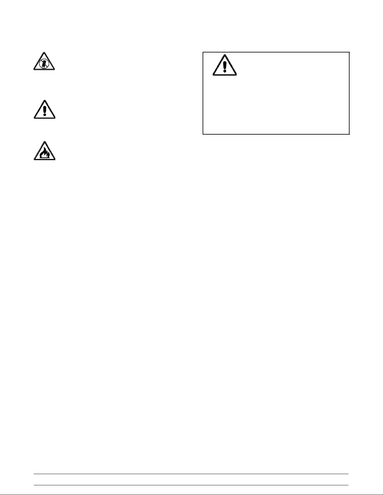
WARNING!
Some consumers are highly allergic to
peanuts, peanut oil, and peanut dust. In
some severe cases, peanut allergy reactions
can cause death. When blending product
with peanuts, make sure excess product is
cleaned from the agitator shaft to eliminate
the fear of product carryover.
NOISE LEVEL: Airborne noise emission does not
exceed 78 dB(A) when measured at a distance of 1.0
meter from the surface of the machine and at a height
of 1.6 meters from the floor.
040406
4
Models BC10/BW11Safety
Page 9

Notes:
Models BC10/BW11 Safety
5
Page 10
Section 4 Operator Parts Identification
BC10
6
Models BC10/BW11Operator Parts Identification
Page 11

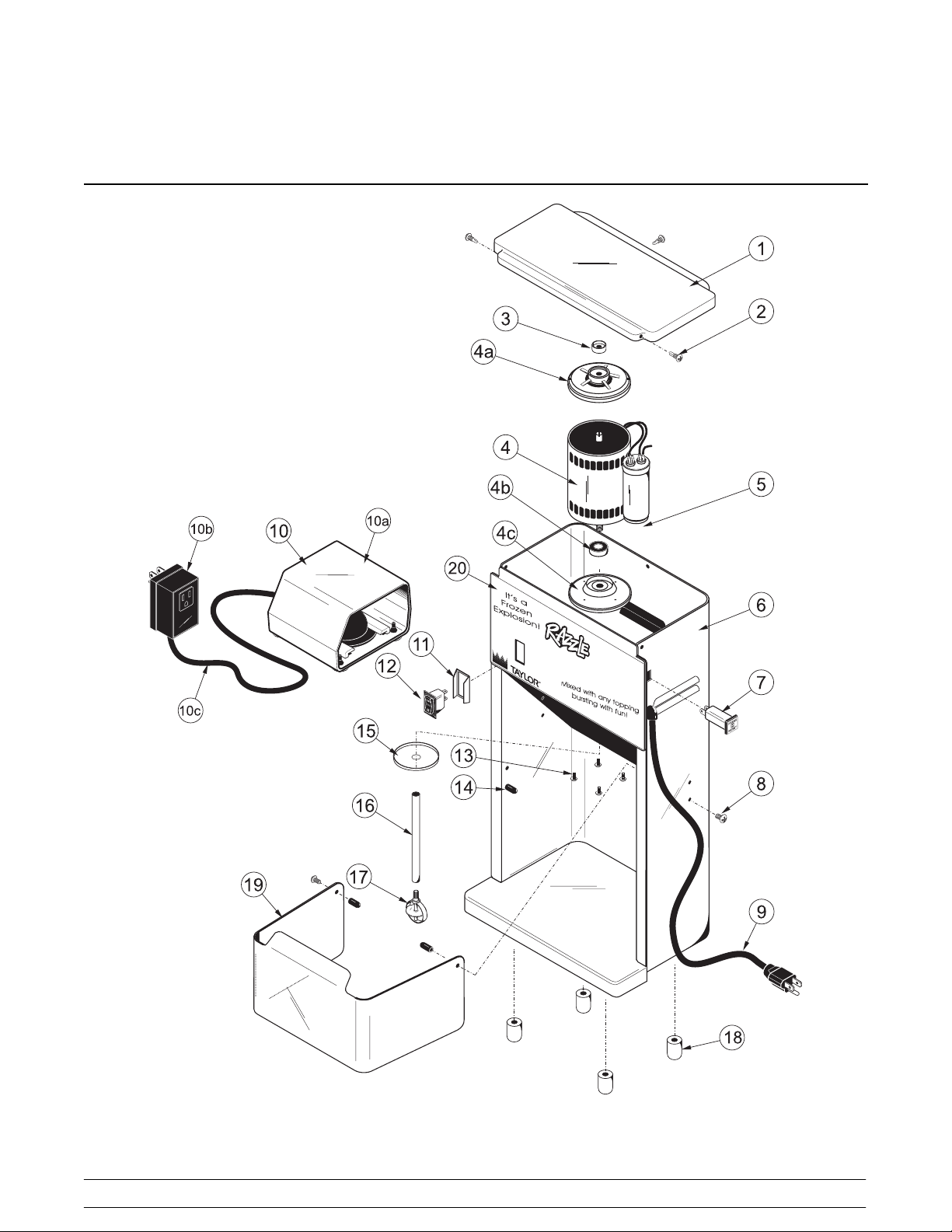
BC10 Exploded View Parts Id en tificatio n
ITEM DESCRIPTION PART NO.
1 CAP-MIXER 051484
2 SCREW-MIXER-RETAINERCAP 051487
3 BRAKE (SEAL)MIXER 051485
MOTOR-MIXER(120V) 051481-12
4
MOTOR-MIXER(220/240V) 051481-27
4a PLATE-MOTOR MOUNTING TOP 051481-4
4b BEARING-MIXER MOTOR 051481-2
4c PLATE-MOTOR MTG. BOTTOM 051481-1
CAPACITOR-MIXER (220/240V) 051483
5
CAPACITOR-MIXER (120V) 051482
6 FRAME-MIXER-STAINLESSSTL 051480
BREAKER-CIRCUIT-MIXER-
3A-120V
7
BREAKER-CIRCUIT-MIXER-
5A-220/ 240V
8 SCREW-MIXER-MTGPIVOT PIN 051508
9 CORD-MIXER-18/3GROUNDED 051491
10 PEDAL-FOOT-MIXER-115V 052451
10* PEDAL-FOOT-MIXER-220V 053192
10a TRANSMITTER FOOT PEDAL 052451-1
10b CONTROLLER-FOOT PEDAL-
115V
051490
051489
052451-2
ITEM DESCRIPTION PART NO.
10b* SWITCH -PRESS.-FOOT PEDAL-
220V
10c TUBE-AIR-FOOT PEDAL 052451-3
11 GUARD-SWITCH-MIXER 051505
12 SWITCH-ROCKER-MIXER 051488
13 SCREW-MIXER-MOTORMTG 051493
14 PIN PIVOT-MIXER 051507
15 SLINGER-MIXER 051494
16 SHAFT-MIXER-AGITATOR-EXT 051495
17 AGITATOR-MIXER-PERM SOFT 051497
18 FOOT A. -MIXER-PLUGGED 051500
19 GUARD-SPLASH-MIXER 051499
20 LABEL-MIXER-COUNTER-
RAZZLE
* CAP-CRIMP-MIXER 051504
* JUMPER WIRES-MIXER 051486
* MANUAL-OPERATOR-MIXER 052544-M
* RELIEF-STRAIN-MIXER-R ANGLE 051492
* TAB INSULATOR-MIXER
(CAPACITOR)
* TIES-CABLE-MIXER
(CAPACITOR)
* NOT SHOWN
053192-1
052250
051509
051502
Models BC10/BW11 Operator Parts Identification
7
Page 12

BW11
8
Models BC10/BW11Operator Parts Identification
Page 13

BW11 Exploded View Parts Identification
ITEM DESCRIPTION PART NO.
1 COVER-MIXER-TOP WALL MT 051516
2 FASTENER-MIXER(BASE & CVR) 051515
3 BRAKE (SEAL) MIXER 051485
MOTOR-MIXER(120V) 051481-12
4
MOTOR-MIXER(220/240V) 051481-27
4a PLATE-MOTOR MTG TOP 051481-4
4b BEARING-MIXER MOTOR 051481-2
4c PLATE -MOTOR MTG BOTTOM 051481-1
CAPACITOR-MIXER (220/240V) 051483
5
CAPACITOR-MIXER (120V) 051482
6 BASE-MIXER-WALL MOUNT 051517
BREAKER-CIRCUIT-MIXER-
3AP-120V
7
BREAKER-CIRCUIT-MIXER-
5A-220/ 240V
8 GUARD-SWITCH-MIXER 051505
9 SWITCH-ROCKER-MIXER 051488
10 PAD VIBRATION DAMPNER
MIXER
11 SCREW-MIXER-MOTOR MTG. 051493
12 BUSHING -MIXER-TRAVEL ROD 051522
13 GUARD-SPLASH-MIXER-CUP-
WALL MOUNT
14 CORD-MIXER-18/3 GROUNDED
W/PLUG
051490
051489
051521
051518
051491
ITEM DESCRIPTION PART NO.
15 BUMPER-MIXER-TRAVEL ROD-
WALL MOUNT
16 ROD TRAVEL-MIXER-WALL MT 051513
17 AGITATOR -MIXER-PERM-SOFT 051497
18 SLINGER -MIXER 051494
19 SHAFT-MIXER-AGITATOR-EXT 051520
20 PEDAL-FOOTMIXER-115V 052451
*20 PEDAL-FOOT MIXER-220V 053192
20a TRANSMITTER-FOOT PEDAL
W/SHROUD
20b CONTROLLER-FOOTPEDAL-
115V
*20b SWITCH-PRESS.-FOOT PEDAL-
220V
20c TUBE-AIR-FOOT PEDAL 052451-3
21 LABEL-MIXER-WALL-FRNT/SIDE 052251
22 KIT-DRIP PAN (INCLUDES
BRACKET)
* JUMPER WIRES-MIXER-WALLMT 051525
* MANUAL-OPERATOR-MIXER 052544-M
* RELIEF STRAIN-MIXER-WALL MT 051524
* TAB INSULATOR-MIXER
(CAPACITOR)
* TIES-CABLE-MIXER
(CAPACITOR)
* KIT-MOUNTING 052428
* NOT SHOWN
051514
052451-1
052451-2
053192-1
052429
051509
051502
Models BC10/BW11 Operator Parts Identification
9
Page 14

Accessories
ITEM DESCRIPTION PART NO.
1 ORGANIZER A. -FLURRY CUP/LID X52080
1a INSERT-SPOON BIN 052113
1b COLUMN-LID 052084
1c SCREW-1/4-15X 1 HEX HEAD 052139
RAZZLE CUP 12 OZ. 1000/CS 051967
2
RAZZLE CUP 16 OZ 1000/CS 051968
ITEM DESCRIPTION PART NO.
3 LID RAZZLE-CLEAR DOME 1000/CS 051969
4 COLLAR-BLUE PLASTIC 051750
5 LIMITER-CUP-STD. MIXER 051526
6 KIT-DRIP PAN (BW11) 052429
7 AGITATOR-MIXER-PERM HARD 051498
10
Models BC10/BW11Operator Parts Identification
Page 15

Optional Dispensers
X52037--1
Item Description Part No.
Dispenser A.-2 Large - 2 Small X52037-1
1 Bracket A.-Wall Mount X52035
2 CanisterA.-Large (2) X53638-1
3 Canister A.-Small (2) X53638-2
4 Kit A.-Dispenser-Wall Mount X52039
4a Screw-10-24x2SltdPanHdSS 051443
4b Anchor-Toggle WingZinc Plated 051444
4c* Template-Dispenser-Wall Mount 052041-T
*Not Shown
X52037--2
Item Description Part No.
Dispenser A.-4 Small (WallMt.)
1 Bracket A.-Wall Mount X52035
2 Canister A.-Small(4) X53638 -2
3 Kit A.-Dispenser-Wall Mount X52039
3a Screw-10-24x2SltdPanHdSS 051443
3b Anchor-Toggle WingZinc Plated 051444
3c* Template-Dispenser-Wall Mount 052041-T
*Not Shown
X52037-2
X52037--3
Item Description Part No.
Dispenser A.-2 Lg,2 Sm X52037-3
1 Bracket A. -Wall Mount X52035
2 Canister A.-Large (2) X53638-3
3 Canister A.-Small (2) X53638-4
4 Kit A.-Dispenser-Wall Mount X52039
4a Screw-10-24x2SltdPanHdSS 051443
4b Anchor-Toggle Wing Zinc Plated 051444
4c* Template-Dispenser-Wall Mount 052041-T
*Not Shown
Models BC10/BW11 Operator Parts Identification
11
Page 16

Optional Dispensers (Cont’d.) X52037--4
Item Description Part No.
Dispenser A.-4 Small (WallMt.)
1 Bracket A.-Wall Mount X52035
2 Canister A.-Small(4) X53638 -4
3 Kit A.-Dispenser-Wall Mount X52039
3a Screw-10-24x2SltdPanHdSS 051443
3b Anchor-Toggle WingZinc Plated 051444
3c* Template-Dispenser-Wall Mount 052041-T
*Not Shown
X52037-4
X52078--1
Item Description Part No.
Dispenser A.-- 2 Small
(Wall/Counter Mount)
1 Bracket A.--Wall/Counter Mt. X51414
2 CanisterA.-Small(2) X53638--2
3 Kit A.-Dispenser-Wall/Counter Mt. X51441
3a Screw--10--24x2SltdPanHd(3) 051443
3b Anchor --Toggle Wing Zinc (3) 051444
3c* Template--Dispenser--Wall Mt. 051415--T
*Not Shown
X52078--1
12
Models BC10/BW11Operator Parts Identification
Page 17

Optional Dispensers (Cont’d.)
X52078--2
Item Description Part No.
Dispenser A.-2 Large
(Wall/Counter Mount)
1 Bracket A.-Wall/Counter Mt. X51414
2 Canister A.-Large (2) X53638 -1
3 Kit A.-Dispenser-Wall/Counter Mt. X51441
3a Screw--10--24x2SltdPanHd(3) 051443
3b Anchor--Toggle Wing Zinc (3) 051444
3c* Template--Dispenser--Wall Mt. 051415--T
*Not Shown
X52078-2
X52566--1
Item Description Part No.
Dispenser A.-2 Large - 2 Small
(Hood/Counter/Wall Mount)
1 Bracket A.-HoodMount X52559
2 Bracket A.-Splitback X52556
3 Bracket A.-Counter/Wall Mt. (2) X52618
4 Canister A.-Small (2) X53638-1
5 Canister A.-Large (2) X53638-2
6 Kit A.-Dispenser-Counter/WallMt X52567
6a Screw-10-24x2SltdPanHd(6) 051443
6b Anchor-Toggle Wing Zinc (6) 051444
6c Collar-Holding (8) 046551
6d Screw-10-32x1/2OvalHd(8) 001251
7 Tray A.-Hood Mount (2) X53773
8* Instruction -Dispenser X52566-INS
*Not Shown
X52566-1
Models BC10/BW11 Operator Parts Identification
13
Page 18

Optional Dispensers (Cont’d.) X52566--2
Item Description Part No.
Dispenser A.-4 Small
(Hood/Counter/Wall Mount)
1 Bracket A.-Hood Mount X52559
2 Bracket A.-Splitback (2) X52556
3 Bracket A.-Counter/Wall Mt (2) X52618
4 Canister A.-Small (4) X53638-2
5 Tray A.-Hood Mount (2) X53773
6 Kit A.-Dispenser-Counter/WallMt X52567
6a Screw-10-24x2SltdPanHd(6) 051443
6b Anchor-Toggle Wing Zinc (6) 051444
6c Collar-Holding (8) 046551
6d Screw-10-32 x 1/2 Oval Hd-NP (8) 001251
7* Instruction-Dispenser X52566-INS
*Not Shown
X52566-2
X52566--3
Item Description Part No.
Dispenser A.-4 Large
(Hood/Counter/Wall Mount)
1 Bracket A.-Hood Mount X52559
2 Bracket A.-Splitback (2) X52556
3 Bracket A.-Counter/Wall Mt (2) X52618
4 Canister A.-Large (4) X53638-1
5 Tray A.-Hood Mount (2) X53773
6 Kit A.-Dispenser-Counter/WallMt X52567
6a Screw-10-24x2SltdPanHd(6) 051443
6b Anchor-Toggle Wing Zinc (6) 051444
6c Collar-Holding (8) 046551
6d Screw-10-32x1/2OvalHd(8) 001251
7* Instruction-Dispenser X52566-INS
*Not Shown
X52566-3
14
Models BC10/BW11Operator Parts Identification
Page 19

Optional Dispensers (Cont’d.) X52566--5
Item Description Part No.
Dispenser A.-2 Large
(Hood Mount Only)
1 Canister A.-Large (2) X53638-1
2 Bracket A.-Splitback (1) X52556
3 Bracket A.-Hood Mount X52559
4 Kit A.-Dispenser-Counter/WallMt X52567-4
4a Screw-10-32x1/2OvalHd(8) 001251
4b Collar-Holding (8) 046551
5 Tray A.-Hood Mount X53773
6* Instruction-Dispenser X52566-INS
*Not Shown
X52566-5
X52566--6
Item Description Part No.
Dispenser A.-2 Large
(WithoutHood Mt. Brkt.)
1 Canister A.-Large (2) X53638-1
2 Bracket A.-Splitback (1) X52556
3 Kit A.-Dispenser-2 Canister X52567-2
3a Screw-10-32x1/2OvalHd(4) 001251
3b Collar-Holding (4) 046551
4 Tray A.-Hood Mount X53773
5* Instruction-Dispenser X52566-INS
*Not Shown
X52566-6
X53407--1
Item Description Part No.
Dispenser A.-2 Small -Vertical
(WallMount Only)
1 Kit A.-VerticalWall Mount X53460
2 CanisterA.-Small (2) X53638-2
3 Kit A.-VerticalWall Mount X53461
3a Screw-10-24x2SltdPanHd(3) 051443
3b Anchor-Toggle Wing Zinc (3) 051444
3c* Template-Dispenser-Wall Mt. 053462-T
*Not Shown
Models BC10/BW11 Operator Parts Identification
15
X53407-1
Page 20

Optional Dispensers (Cont’d.) X53492--1
Item Description Part No.
Dispenser A.-1 Large - Vertical
(WallMount Only)
1 CanisterA.-Large (1) X53638-1
2 Bracket A.-VerticalWall Mount X53488
3 Kit A.-Dispenser-Wall Mount X53490
3a Screw-10-24x2SldtPanHd(3) 051443
3b Anchor-Toggle Wing Zinc (3) 051444
Template-Single Canister-Wall Mt 053491-T
3c*
*Not Shown
X53492-1
X53492--2
Item Description Part No.
Dispenser A.-1 Small - Vertical
(WallMount Only)
1 CanisterA.-Small(1) X53638-2
2 Bracket A.-VerticalWall Mount X53488
3 Kit A.-Dispenser-Wall Mount X53490
3a Screw-10-24x2SldtPanHd(3) 051443
3b Anchor-Toggle Wing Zinc (3) 051444
Template-Single Canister-Wall Mt 053491-T
3c*
*Not Shown
X53492-2
16
Models BC10/BW11Operator Parts Identification
Page 21

Optional Large Candy Dispenser Canister Assembly (X53638--1)
ITEM DESCRIPTION PART NO.
1 CANISTER A.-LARGE CANDY DISP. X53638-1
1a COVER-CANDY DISPENSER-LARGE 052032-1
1b SHAFT A.-LONG W/AGITATORS X53530-1
1c PLATE--ANTI--ROTATION INS. W/POST 053581
Models BC10/BW11 Operator Parts Identification
ITEM DESCRIPTION PART NO.
1d PUCK A.-CANDY DISPENSER X52027
1e CANISTER-CANDY DISPENSER-LG. 052033-1
1f KNOB A.-CANDY DISPENSER X51564
17
Page 22

Optional Small Candy Dispenser Canister Assembly (X53638--2)
ITEM DESCRIPTION PART NO.
2 CANISTER A.-SM. CANDY DISP. (2) X53638-2
2a COVER-CANDY DISPENSER- SMALL 052032-2
2b SHAFT A.-SHORT W/AGITATORS X53530-2
2c PLATE--ANTI--ROTATION INS. W/POST 053581
ITEM DESCRIPTION PART NO.
2d PUCK A.-CANDY DISPENSER X52027
2e CANISTER-CANDY DISPENSER- SM. 052033-2
2f KNOB A.-CANDY DISPENSER X51564
18
Models BC10/BW11Operator Parts Identification
Page 23

Section 5 Important: To the Operator
Control Switch
When placed in the “ON” position, the agitator
activates to blend product.
Figure 1
Reset Switch
The reset switch is located above the control switch on
the front panel. The reset switch protects the motor
from an overload condition. If an overload occurs, the
reset mechanism will trip. To properly reset the unit,
make sure the control switch is in the “OFF” position.
Press the reset switch and resume operation.
Figure 3
Splash Guard
Foot Pedal
A grounded foot pedal allows the operator to use both
hands to mix product.
Figure 2
Note: Some International units are not equipped with
this feature.
The splash guard functions as a built-in cup limiter
which prevents the cups from agitator penetration.
The splash guard also helps keep the inside of the
housing clean.
The splash guard for the Model BC10 (counter-top)
slides up and down on stainless steel rods. The splash
guard for the Model BW11 (wall mount) rotates upward
for easy operation.
Figure 4
Models BC10/BW11 Important: To the Operator
19
Page 24

Motor
The motor features a heavy duty, ball bearing induction
motor and does not use brushes, belts, couplings, or
gears. This design reduces power consumption, heat,
noise, and wear. The motor maintains an optimal
speed of 3,485 RPM to maintain product consistency.
Permanent Agitator
The permanent agitator is manufactured from FDA
and NSF approved, food safe material. The shaft
must be cleaned between servings as product
carryover will occur. (See page 23.)
Figure 5
Candy Dispenser Canisters
The canisters contain the candy toppings. The
operator dispenses the toppings by use of the
dispenser handle.
Candy Care
Most candies have a tendency to “lump” or “cluster”
under various conditions. This can lead to broken
dispensing pucks if excessive pressure is required to
move the handle.
S Store candies in the proper ambient
conditions according to the manufacturer’s
directions. Avoid excessively hot and humid
locations.
S Avoid opening a bag of candy if the entire
contents cannot be poured into the canister.
If this cannot be avoided, be sure to fold the
bag opening over and reseal it with a bag
clip. Store it in a cool, dry place until needed
again.
S Rotate the candy stock to use the oldest
candy first (First in--First--out).
S Before opening a new bag of candy, check
to see if it contains large lumps by slightly
squeezing the bag. If lumps exist, gently
break them apart with your fingers prior to
opening the bag.
Canister Care an d Location
S Avoid mounting canisters near heat,
humidity, or hot air discharges. These
conditions can promote lumping and difficult
dispensing of candies.
S Always keep candies protected from the
open ambience by having the lids properly
installed on top of the canisters when
candies are present.
S When canisters are not cleaned daily, candy
dust and powers begin to congeal and will
cause excessive pressure to be exerted in
order to dispense candies. This additional
pressure can cause the pucks to break.
S Avoid “slamming” the dispensing handle
back and forth when dispensing candies.
This can cause the puck to break.
S Do not apply undue force on the handle to
make the puck move. If a “lock up” condition
occurs, empty the dispenser of candies.
Disassemble, clean and thoroughly dry the
dispenser according to cleaning instructions.
Eliminate clusters and lumps before refilling
the canister.
S When reassembling the canister, take care
not to over--tighten the handle into the “puck
bushing”. After the handle has been
screwed into the puck bushing, check
tightness by unscrewing it slightly to be sure
it requires little effort to unscrew. Then
reseat it.
030103
20
Models BC10/BW11Important: To the Operator
Page 25

Section 6 Operating Procedures
Mixing Instructions
Make sure your hands are clean and sanitized before
performing these steps.
Step 1
Fill a serving cup with soft serve product and install the
plastic domed lid.
Step 2
Add “mix-in” ingredients such as liquid flavoring,
candy, cookies, fruit, or other condiments.
Figure 8
Step 3
Place the control switch in the “ON” position.
Step 4
Hold the cup securely in place beneath the agitator,
and step on the foot pedal. Using a circular motion,
work the cup upward and over the spinning agitator.
Figure 6
Figure 9
Select International Units: For select International
units which are not equipped with a foot pedal, the
control switch must be pressed during agitation.
Note: Agitation will chip and break down solids. It is
not intended to completely pulverize ingredients
because solid chunks should be evident in the finished
Figure 7
Models BC10/BW11 Operating Procedures
product.
21
Page 26

CAUTION: The permanent agitator is designed to
withstand reasonable contact with the spinning
agitator shaft. However , it should not be forced or held
solidly against the side or bottom of the cup. This may
cause damage to the cup or components.
Cleaning
The Taylor Company recommends daily cleaning.
Step 5
After about 10 seconds have elapsed, slowly remove
the cup by “swirling” it around the agitator. This will
create an effect that is pleasing to the eye, and avoids
leaving a hole in the center of the product.
Step 6
Before removing the cup completely, hold the top edge
of the cup near the spinning agitator to allow excess
mixture to be projected into the cup or the mix-through
collar.
Step 7
Release the foot pedal or place the control switch in the
“OFF” position.
Step 8
Prepare a durable container with an approved cleaning
solution (example: Kay-5r). USE HOT WATER
(110_F/43_C) AND FOLLOW THE MANUFACTURER’S SPECIFICATIONS. If another approved cleaner
is used, dilute according to label instructions.
(IMPORTANT: Follow label directions, as too
STRONG of a solution can cause parts damage, while
too MILD of a solution will not provide adequate
cleaning.) Make sure all brushes provided with the
freezer are available for brush cleaning. Do not use a
solution that contains ammonia.
Note: The container must be deep enough to
submerge the entire agitator and shaft.
Step 9
Submerge the agitator in the cleaning solution, all the
way to the bottom of the motor chamber. Step on the
foot pedal or place the control switch in the “ON”
position. Allow the agitator to run for about 15 seconds.
Repeat this step several times, making certain all
portions of the agitator and shaft have been
submerged in the cleaning solution.
ALWAYS FOLLOW LOCAL HEALTH CODES
Step 1
Prepare a sink with an approved cleaning solution
(example: Kay-5r). USE HOT WATER (110_F/43_C)
AND FOLLOW THE MANUFACTURER’S
SPECIFICATIONS. Do not use a solution that
contains ammonia, and avoid placing components in
a dishwasher.
Step 2
Disconnect power from the wall
receptacle. Failure to comply may result in
electrical shock.
Step 3
Remove the splash guard.
Wall mount units only (BW11):
Remove the sliding splash guard cup by squeezing the
travel rods together and sliding the guard downward.
Take the cup to the sink for cleaning.
Step 4
Wash the splash guard in the approved cleaning
solution.
Step 5
Using a single service towel (moistened with the
cleaning solution), wipe clean the travel rods and the
agitator shaft.
CAUTION: DO NOT REMOVE THE TRA VEL RODS
FROM THE UNIT.
Step 6
Remove the dispenser from the bracket by tilting it
toward you and lifting upward.
Step 7
Discard any remaining topping.
WARNING: Never try to wipe clean the
agitator while it is active. Failure to follow these
instructions can lead to severe personal injury
from hazardous moving parts, or damage to the
unit.
030103
Step 8
Remove the cover, shaft, dispensing plate, and
dispensing puck. Unscrew the handle from the
dispensing puck.
Step 9
Check all parts for cracks and damage, especially the
puck. Replace damaged parts immediately.
22
Models BC10/BW11Operating Procedures
Page 27

Step 10
Wash all plastic parts in the approved cleaning
solution. CAUTION: PLASTIC PARTS ARE NOT
DISHWASHER SAFE! HAND WASH ONLY!
Step 11
Re-assemble the dispenser. Make sure the dispensing
puck is placed in the canister with the counterbore face
down and with the threaded insert facing the slot.
Note: Parts must be dry prior to assembling and
refilling them with mix ingredients.
Step 12
Screw the handle through the slot and into the metal
insert in the dispensing puck. Place the dispensing
plate on top of the dispensing puck.
Step 13
Position the shaft through the plate and into the slot in
the dispensing puck. Make certain the shaft is properly
seated.
Step 14
Install the dispenser. Place the dispenser on the wall
bracket with the locating pin facing the holding bracket.
The dispenser must be tilted toward the operator to
clear the handle. Insert the pin into the hole in the
bracket.
Note: When loading the dispenser with product, keep
powder away from the top of the shaft. Fill the canister
only within one inch of the top. Do not overfill the
canister.
Step 15
Wipe clean all stainless steel surfaces with an
approved, non-abrasive commercial cleaner. This
includes the mixer, dispenser, and organizer surfaces.
CAUTION: The foot pedal should be kept
dry. Do not leave it on the floor during mopping.
Failure to comply may result in electrical shock.
Permanent Agitator Cleaning
Step 1
Prepare a durable container with an approved cleaning
solution (example: Kay-5r). USE HOT WATER
(110_F/43_C) AND FOLLOW THE MANUFACTURER’S SPECIFICATIONS. Do not use a solution that
contains ammonia.
Note: The container must be deep enough to
submerge the entire agitator and shaft.
Step 2
Submerge the agitator in the cleaning solution, all the
way to the bottom of the motor chamber. Step on the
foot pedal or place the control switch in the “ON”
position. Allow the agitator to run for about 15 seconds.
Repeat this step several times, making certain all
portions of the agitator and shaft have been
submerged in the cleaning solution.
WARNING: Never try to wipe clean the
agitator while it is active. Failure to follow these
instructions can lead to severe personal injury
from hazardous moving parts, or damage to the
unit.
Step 3
Repeat Step 2 using cool, clean water in lieu of
cleaning solution.
Sanitizing
Step 1
Repeat all steps of the cleaning procedure using an
WARNING: Do not spray water or other
liquid around the motor chamber. Do not use
excess liquid around the switch, motor protector,
power cords, or cord entry orifice. Make certain all
areas in and around the motor are dry before
connecting power to the wall receptacle. Failure to
comply may cause equipment damage or
personal injury due to electric shock.
Step 16
When foot pedal cleaning is required, disconnect it and
wipe it with a damp single service towel. Make sure the
foot pedal is thoroughly dry before re-connecting it to
the unit.
Models BC10/BW11 Operating Procedures
approved 100 PPM sanitizing solution (example:
R). USE WARM WATER AND FOLLOW THE
Kay-5
MANUFACTURER’S SPECIFICATIONS.
Step 2
Reinstall the splash guard.
Step 3
Repeat the sanitizing procedures at the start of the
day.
ALWAYS FOLLOW LOCAL HEALTH CODES
23
030103
Page 28

Section 7 Parts List
UPDATE
REMARKS PARTS
WARR.
CLASS
QTY.
BW11
QTY.
BC10
NUMBER
DESCRIPTION PART
PLATE-MOTOR-MOUNTING 051481-1 1 1 000
BEARING-MIXER MOTOR 051481-2 1 1 000
SCREW-MOTOR MOUNTING 051481-3 4 4 000
PLATE-MOTOR-MOUNTING 051481-1 1 1 000
BEARING-MIXER MOTOR 051481-2 1 1 000
SCREW-MOTOR MOUNTING 051481-3 4 4 000
AGITATOR-MIXER-PERM SOFT SERVE 051497 1 1 000 SOFT SERVE ONLY
AGITATOR-MIXER-PERM HARD SERVE 051498 1 1 000 HARD SERVE ONLY
BASE-MIXER-WALL MOUNT 051517 1 000
BRAKE (SEAL) MIXER 051485 1 1 000
BREAKER-CIRCUIT-3 AMP (120V) 051490 1 1 000
BREAKER-CIRCUIT-5 AMP (220/240V) 051489 1 1 000
BUMPER-TRAVEL ROD 051514 1 000
BUSHING-TRAVEL ROD 051522 4 000
CAP-MIXER 051484 1 000
CAP-CRIMP-MIXER 051504 2 000
CAPACITOR-MIXER (120V) 051482 1 1 000
CAPACITOR-MIXER (220/240V) 051483 1 1 000
CORD-MIXER-18/3 GROUNDED 051491 1 1 000
COVER-MIXER-TOP-WALL MOUNT 051516 1 000
FASTENER-MIXER 051515 8 000
FOOT A.-MIXER-PLUGGED 051500 4 000
GUARD-SPLASH-MIXER 051499 1 000
GUARD-SPLASH-MIXER-CUP 051518 1 000
GUARD-SWITCH-MIXER 051505 1 1 000
JUMPER WIRES-MIXER 051486 2 000
JUMPER WIRES-WALL MOUNT 051525 2 000
KIT-DRIP PAN *BW11* 052429 1 000
KIT-MOUNTING *BW11* (BRACKET) 052428 1 000
LABEL-MIXER-COUNTER-RAZZLE 052250 1 000
LABEL-MIXER-WALL MOUNT-RAZZLE 052251 3 000
LIMITER-CUP 051526 1 000
MAN-OPER-MIXER-RAZZLE 052544-M 1 1 000
BC10 / BW11 Razzle Blenders
MOTOR-MIXER (120V) 051481-12 1 1 000 INCLUDES CAPACITOR 130
MOTOR-MIXER (220/240V) 051481-27 1 1 000 INCLUDES CAPACITOR 130
+ Available Separately
Parts List Models BC10/BW11
24
PAD-VIBRATIONDAMPNER 051521 1 000
Page 29

UPDATE
REMARKSWARR.
CLASS
QTY.
BW11
QTY.
BC10
PART
NUMBER
DESCRIPTION PARTS
TRANSMITTER-FOOT PEDAL 052451-1 1 1 000 INCLUDES SHROUD 131
CONTROLLER-FOOT PEDAL-115VOLT 052451-2 1 1 000 131
TUBE-AIR-FOOT PEDAL 052451-3 1 1 000 131
TRANSMITTER-FOOT PEDAL 052451-1 1 1 000 136
PEDAL-FOOT-MIXER-115 VOLT 052451 1 1 000 NEW STYLE (REPLACES 051501)
+ Available Separately
PEDAL-FOOT-MIXER-220 VOLT 053192 1 1 000 S/N 912480000/UP (5/4/98) - 50HZ 136
SWITCH-PRESSURE-220V 053192-1 1 1 000 136
TUBE-AIR-FOOT PEDAL 052451-3 1 1 000 136
PIN-PIVOT 051507 4 000 FOR SPLASH GUARD-051499
RELIEF STRAIN-MIXER-WALLMOUNT 051524 1 000
RELIEF STRAIN-MIXER-RIGHT ANGLE 051492 3 000
ROD-TRAVEL 051513 1 000
SCREW-MIXER-RETAINER CAP 051487 3 000
SCREW-MIXER-MOUNTING PIVOT PIN 051508 4 000 FOR PIVOT PIN-051507
SCREW-MIXER-MOTOR MOUNTING 051493 4 4 000
SHAFT-MIXER-AGITATOR EXTENSION 051495 1 000
SHAFT-MIXER-AGITATOR EXTENSION 051520 1 000
SPACER-TUBE-12 OZ CUP 051523 2 000 4/00 / PRIOR
SLINGER-MIXER 051494 1 1 000
SWITCH-ROCKER 051488 1 1 000
TAB-INSULATOR 051509 1 1 000
TIES-CABLE 051502 3 3 000
TEMPLATE-DISP. WALL MOUNT 051415-T 1 000
Models BC10/BW11 Parts List
25
Page 30

UPDATE
REMARKS PARTS
CLASS
QTY. WARR.
NUMBER
DESCRIPTION PART
CANISTER-CANDY TOP. DISP.LARGE 052033-1 1 000
BRACKET A.-CANDY DISP.WALL MNT X52035 1 000
CANISTER A.-LARGE CANDY DISP. X53638-1 2 000
Candy Dispenser Blender Accessories
+ Available Separately
DISPENSER A.-2 LARGE & 2 SMALLCAN. X52037-1
COVER-CANDY TOP. DISP.-LARGE 052032-1 1 000
KNOB A.-CANDY TOPPING DISP. X51564 1 000
KNOB-CANDY TOPPING DISP. 051412 1 000
STUD-CANDY DISPENSER 1/4-20 051413 1 000
PLATE-INSERT CAN. TOP. DISP. 053581 1 000
PUCK A.-CANDY TOPPING DISP. X52027 1 000
SHAFT A.-LARGE CANDY TOPPING X53530-1 1 000
CANISTER A.-SMALLCANDY DISP X53638-2 2 000
CANISTER-CANDY TOP. DISP.SMALL 052033-2 1 000
COVER-CANDY TOP. DISP.-SMALL 052032-2 1 000
KNOB A.-CANDY TOPPING DISP. X51564 1 000 SEE BREAKDOWN ABOVE
PLATE-INSERT CAN. TOP. DISP. 053581 1 000
PUCK A.-CANDY TOPPING DISP. X52027 1 000
SHAFT A.-SMAL LCANDY TOPPING X53530-2 1 000
KIT A.-DISPENSER WALL MOUNT X52039 1 000
ANCHOR-TOGGLE WING ZINC PLAT 051444 3 000
SCREW-10-24X2 SLTD PAN HD SS 051443 3 000
TEMPLATE-DISPENSER WALL MOUNT 052041-T 1 000
CANISTER-CANDY TOP. DISP.LARGE 052033-1 1 000
COVER-CANDY TOP. DISP.-LARGE 052032-1 1 000
KNOB A.-CANDY TOPPING DISP. X51564 1 000 SEE BREAKDOWN ABOVE
PLATE-INSERT*W/POSTS*LG PUCK* 053582 1 000
PUCK A.- LARGE CANDY DISPENSER X51404 1 000
SHAFT A.-LARGE CANDY TOPPING X53530-1 1 000
BRACKET A.-CANDY DISP.WALL MNT X52035 1 000
CANISTER A.-SMALLCANDY DISP X53638-2 2 000 SEE BREAKDOWN ABOVE
KIT A.-DISPENSER WALL MOUNT X52039 1 000 SEE BREAKDOWN ABOVE
DISPENSER A.-4 SMALL CAN. X52037-2
BRACKET A.-CANDY DISP.WALL MNT X52035 1 000
CANISTER A.-LARGE W/LARGE PUCK X53638-3 2 000
DISPENSER A.-2 LG/ 2SM*LG PUCKS X52037-3
Parts List Models BC10/BW11
26
Page 31

UPDATE
REMARKSWARR.
CLASS
QTY.PART
NUMBER
DESCRIPTION PARTS
CANISTER-CANDY TOP. DISP.SMALL 052033-2 1 000
COVER-CANDY TOP. DISP.-SMALL 052032-2 1 000
KNOB A.-CANDY TOPPING DISP. X51564 1 000 SEE BREAKDOWN ABOVE
PLATE-INSERT*W/POSTS*LG PUCK* 053582 1 000
PUCK A.- LARGE CANDY DISPENSER X51404 1 000
CANISTER A.-SMALLW/LARGE PUCK X53638-4 2 000
+ Available Separately
SHAFT A.-SHORT W. AGITATORS X53530-2 1 000
KIT A.-DISPENSER WALL MOUNT X52039 1 000 SEE BREAKDOWN ABOVE
ANCHOR-TOGGLE WING ZINC PLAT 051444 3 000
SCREW-10-24X2 SLTD PAN HD SS 051443 3 000
TEMPLATE-DISP. WALL MOUNT 051415-T 1 000
BRACKET A.-CANDY DISP.WALL MNT X52035 1 000
KIT A.-DISPENSER WALL MOUNT X52039 1 000 SEE BREAKDOWN ABOVE
CANISTER A.-SMALLW/LARGE PUCK X53638-4 4 000 SEE BREAKDOWN ABOVE
DISPENSER A.- 4 SMALL LG. PUCK X52037-4
BRACKET A.-2CANISTERS X51414 1 000
CANISTER A.-SMALLCANDY DISP. X53638-2 2 000 SEE BREAKDOWN ABOVE
KIT A.-DISPENSER-2CANISTER MOUNT X51441 1 000
DISPENSER A.-2 SMALL CAN. X52078-1
BRACKET A.-2CANISTERS X51414 1 000
CANISTER A.-LARGE CANDY DISP. X53638-1 2 000 SEE BREAKDOWN ABOVE
KIT A.-DISPENSER-2CANISTER MOUNT X51441 1 000 SEE BREAKDOWN ABOVE
DISPENSER A.-2 LARGE CAN. X52078-2
BRACKET A.-SPLITBACKDISP. X52556 2 000
BRACKET A.-HOOD*8634*8784* X52559 1 000
CANISTER A.-LARGE CANDY DISP. X53638-1 2 000 SEE BREAKDOWN ABOVE
CANISTER A.-SMALLCANDY DISP. X53638-2 2 000 SEE BREAKDOWN ABOVE
DISPENSER A.-HOOD/COUNTER MOUNT X52566-1 2 SMALL, 2 LARGE CANISTERS
INSTRUCTION-CANDY DISP. X52566-INS 1 000
KIT A.-HOOD/COUNTER/WALL MNT X52567 1 000
SCREW-10-32X1/2 OVAL HD-NP 001251 8 000
COLLAR-HOLDING 046551 8 000
SCREW-10-24X2 SLTD PAN HD SS 051443 6 000
ANCHOR-TOGGLE WING ZINC PLAT 051444 6 000
BRACKET A.-COUNTERTOP/WALL MT X52618 2 000
Models BC10/BW11 Parts List
27
Page 32

UPDATE
REMARKSWARR.
CLASS
QTY.PART
NUMBER
DESCRIPTION PARTS
STRIP-MAGNETIC 2” L 042814-2 4 000 152
TRAY A.-HOOD MOUNT X53773 2 000 152
+ Available Separately
BRACKET A.-SPLITBACKDISPENSER X52556 2 000
BRACKET A.-HOOD*8634*8784* X52559 1 000
DISPENSER A.-HOOD/COUNTER MOUNT X52566-2 4SMALL
CANISTER A.-SMALLCANDY DISP X53638-2 2 000 SEE BREAKDOWN ABOVE
INSTRUCTION-CANDY DISPENSER X52566-INS 1 000
KIT A.-HOOD/COUNTER/WALL MNT X52567 1 000 SEE BREAKDOWN ABOVE
TRAY A.-HOOD MOUNT X53773 2 000 SEE BREAKDOWN ABOVE 152
SCREW-10-32X1/2 OVAL HD-NP 001251 8 000
COLLAR-HOLDING 046551 8 000
CANISTER A.-LARGE CANDY DISP X53638-1 2 000 SEE BREAKDOWN ABOVE
INSTRUCTION-CANDY DISPENSER X52566-INS 1 000
KIT A.-HOOD/COUNTER/WALL MNT X52567 1 000 SEE BREAKDOWN ABOVE
TRAY A.-HOOD MOUNT X53773 2 000 SEE BREAKDOWN ABOVE
BRACKET A.-SPLITBACK DISPENSER X52556 2 000
BRACKET A.-HOOD X52559 1 000
KIT A.-HARDWARE FOR HD MNT BKT X52567-4 1 000
KIT A. HOOD MOUNT BRK’S ONLY X52566-4 LESS CANISTERS
TRAY A.-HOOD MOUNT X53773 2 000 SEE BREAKDOWN ABOVE 152
BRACKET A.-SPLITBACK DISPENSER X52556 1 000
BRACKET A.-HOOD X52559 1 000
CANISTER A.-LARGE CANDY DISP X53638-1 2 000 SEE BREAKDOWN ABOVE
DISPENSER A.-HOOD MNT/ONLY 2LG X52566-5
BRACKET A.-SPLITBACKDISPENSER X52556 2 000
BRACKET A.-HOOD*8634*8784* X52559 1 000
DISPENSER A.-HOOD MNT. 4 LARGE X52566-3
INSTRUCTION-CANDY DISPENSER X52566-INS 1 000
KIT A.-HARDWARE FOR HD MNT BKT X52567-4 1 000
TRAY A.-HOOD MOUNT X53773 1 000 SEE BREAKDOWN ABOVE 152
CANISTER A.-LARGE CANDY DISP X53638-1 2 000 SEE BREAKDOWN ABOVE
INSTRUCTION-CANDY DISPENSER X52566-INS 1 000
BRACKET A.-SPLITBACK DISPENSER X52556 1 000
DISPENSER A.-2LG CAN. W. BRKT X52566-6
Parts List Models BC10/BW11
28
Page 33

UPDATE
REMARKSWARR.
CLASS
QTY.PART
NUMBER
DESCRIPTION PARTS
SCREW-10-32X1/2 OVAL HD-NP 001251 4 000
COLLAR-HOLDING 046551 4 000
KIT A.- 2 CAN./DISP. HARDWARE X52567-2 1 000
+ Available Separately
TRAY A.-HOOD MOUNT X53773 1 000 SEE BREAKDOWN ABOVE 152
DISPENSER A.-2 SMALL*VERTICAL X53407-1
BRACKET A.-2VERTICAL WALL MNT X53460 1 000
CANISTER A.-SMALLCANDY DISP X53638-2 2 000 SEE BREAKDOWN ABOVE
KIT A. 2 VERTICAL WALL MOUNT X53461 1 000
SCREW-10-32X1/2 OVAL HD-NP 001251 3 000
COLLAR-HOLDING 046551 3 000
BRACKET A.-SINGLE CAN. WALL MNT X53448 1 000
CANISTER A.-LARGE CANDY DISP X53638-1 1 000 SEE BREAKDOWN ABOVE
KIT A.- SINGLE CAN. WALLMOUNT X53490 1 000
DISPENSER A.- LG - SNGL WALL MNT X53492-1
BRACKET A.-SINGLE CAN. WALL MNT X53448 1 000
CANISTER A.-SMALLCANDY DISP X53638-2 1 000 SEE BREAKDOWN ABOVE
KIT A.- SINGLE CAN. WALLMOUNT X53490 1 000 SEE BREAKDOWN ABOVE
DISPENSER A.- SM - SNGL WALL MNT X53492-2
ACCESSORIES
COLLAR-BLUE PLASTIC 051750 000
CUP-12 OZ RAZZLE (1000/CASE) 051967 000
CUP-16 OZ RAZZLE (1000/CASE) 051968 000
LID- RAZZLE (1000/CASE) 051969 000
ORGANIZER A.-CUP/LID X52080 000
SCREW-10-24X 2 SLTD PAN HD 051444 000
ANCHOR-TOGGLE WING ZINC PLATED 051443 000
TEMPLATE-ORGANIZER MOUNT 052177-T 000
COLUMN-LIDORGANIZER 052084 000
SCREW-1/4-15 X 1 HEX (COLUMN) 052139 000
INSERT-SPOON BIN 052113 000
Models BC10/BW11 Parts List
29
Page 34

Wiring Diagram
Wiring Diagram Models BC10/BW11
30
 Loading...