

Tascam DR-701D Owners Manual

DR-701D
®
Linear PCM Recorder for DSLR
REFERENCE MANUAL
D01276520B

Contents
1 – Introduction ..............................................4
Features .................................................................................. 4
Conventions used in this manual ..................................4
Trademarks ............................................................................ 5
About SD cards .................................................................... 5
Precautions for use ...................................................... 5
2 – Names and functions of parts .................. 6
Front panel ............................................................................6
Rear panel .............................................................................. 6
Left side .................................................................................. 7
Right side ............................................................................... 8
Top ............................................................................................ 8
Bottom .................................................................................... 9
Home Screen ........................................................................ 9
Menu structure .................................................................. 10
Basic Menu Screen operations .....................................12
Menu operation procedures ..................................12
Basic operation ..................................................................12
3 – Preparation ..............................................13
Powering the unit .............................................................13
Power sources .............................................................13
Using AA batteries ..................................................... 13
Using an AC adapter (sold separately) ................ 13
Using an external battery pack (sold separately)
13
Using USB bus power................................................14
Turning the power on and off (putting it in standby)
14
Turning the unit on .................................................... 14
Turning the unit off (putting it in standby) .......14
Resume function ........................................................ 14
Setting the date and time .............................................. 15
Inserting and removing SD cards ................................15
Inserting the card .......................................................15
Removing the card .................................................... 15
SD card write protection switches ....................... 15
Preparing an SD card for use ........................................16
Camera connections ........................................................16
Setting the input functions ...........................................17
Recording with the built-in mics ..........................17
Connecting microphones ....................................... 17
Recording an external device (LINE IN) .............. 17
Connecting a time code generator ............................17
Connecting monitoring equipment ..........................18
Adjusting the playback volume ...................................18
Monitoring...........................................................................19
Selecting the monitored signals ...........................19
Using the accessory shoe on the top panel ............19
4 – Recording ................................................20
Setting where to save files .............................................20
Setting the recording input sources ..........................20
Adjusting the input level ................................................20
Compensating for mic distances ................................. 21
Setting phase reversal for individual channels ......21
Set the power sources used by mics ..........................22
Setting phantom power ..........................................22
Setting the phantom power voltage ..................22
Setting plug-in power ..............................................23
Using the limiter ................................................................23
Setting automatic level control (ALC) ........................24
Setting the low-cut filter ................................................ 24
Setting the recording file type, file format
and sampling frequency ................................................24
Setting channels to record ............................................25
Make MIX channel recording settings .......................25
Recording (MONO/STEREO/POLY (6ch)) ...................25
Starting recording ...................................................... 25
File names when the FILE TYPE is MONO ..........25
File names when the FILE TYPE is STEREO ........25
File names when POLY (6ch) recording ..............25
Creating a new file while continuing to record
(file incrementing) ............................................................26
Manually incrementing files during recording
Automatically incrementing files during
recording .......................................................................26
Simultaneously recording two files at different
input levels (DUAL REC) ..................................................26
Enabling dual recording ..........................................26
Starting dual recording ............................................ 26
Dual recording file names ....................................... 26
Using mark functions.......................................................27
Adding marks manually to a recording .............27
Moving to a mark position ......................................27
Using the auto tone function .......................................27
Setting the auto tone function .............................27
Setting the volume of auto tones and slate
tones ............................................................................... 27
Using the oscillator .................................................... 27
Recording slate tones ......................................................28
Moving to slate tone insertion positions ...........28
Inputting time code and adding recording start
times to files ........................................................................ 28
Setting the time code source input .....................28
Setting the power off generator function ........29
Checking the time code counter ..........................29
Outputting this unit's audio as the HDMI output
audio ......................................................................................29
Outputting the audio of each input channel
from the HDMI output..............................................29
Outputting the MIX audio from the HDMI
output ............................................................................29
Recording duration ..........................................................30
..26
TASCAM DR-701D
2

Contents
5 – Working with Files and Folders
(Browse Screen) ............................................31
Navigating the Browse Screen ..................................... 31
Icons on the Browse Screen ..........................................31
File operations ...................................................................31
Folder operations ..............................................................32
Creating a new folder ......................................................32
Using the MEDIA menu page to create
a folder ...........................................................................32
Using NEW FOLDER on the Browse Screen.......32
6 – Playback ...................................................33
Playing recordings ............................................................33
Pausing playback........................................................33
Stopping playback .....................................................33
Searching backward and forward ........................33
Jumping between playback positions ...................... 33
Playing dual recording files ........................................... 33
7 – Mixer ........................................................34
Setting the mixer ..............................................................34
Using mid-side microphones .......................................34
Adjusting the stereo width .....................................34
Setting the GANG operation mode ............................34
12 – Troubleshooting ....................................41
13 – Specifications ........................................42
General .................................................................................42
Input/output ratings ........................................................42
Analog audio input and output ratings ............. 42
Control input/output ratings ................................. 42
Audio performance ..........................................................43
General .................................................................................43
Dimensional drawings ....................................................44
8 – Connecting with a Computer .................35
Transferring files to a computer ..................................35
Transferring files from a computer .............................35
Disconnecting from a computer .................................35
9 – Settings and Information .......................36
Setting the file name format ........................................36
Setting the WORD item ............................................36
Resetting the count ...................................................36
Format an SD card ............................................................36
Adjusting the display contrast .....................................37
Setting the peak hold time ............................................37
Setting trim operation mute .........................................37
Making power management settings .......................37
Setting the type of batteries ..................................37
Set the automatic power saving function .........37
Setting the backlight ................................................ 37
Restoring factory default settings .............................. 37
Viewing File Information ................................................ 38
File information page (PROJECT) ..........................38
Card information page (CARD) ..............................38
System information page (SYSTEM) ....................38
10 – Using the REMOTE jack .........................39
Using a footswitch (TASCAM RC-3F)...........................39
Setting up the footswitch ....................................... 39
Using the footswitch .................................................39
Using a remote control (TASCAM RC-10) ..................39
Setting up a remote control ................................... 39
Using the remote control ........................................39
11 – Messages ................................................40
TASCAM DR-701D
3

1 – Introduction
Features
This audio recorder includes audio outputs and functions
designed for use with digital single-lens reflex (DSLR) cameras
and video cameras, enabling the recording of high-quality
audio.
•
Compact audio recorder that uses SD/SDHC/SDXC cards as
recording media
•
TASCAM High Definition Discrete Architecture (HDDA)
microphone preamps provide high-quality recording inputs
•
Four channels can be mixed down to two for stereo output
•
Recording levels can be adjusted independently for all
channels
•
GANG trim function enables linked control of multiple trims
while retaining level differences
•
Clock synchronization with a camera possible using an
HDMI connection
•
Support for HDMI time code recording triggers
•
Support for HDMI time code and LTC time code input (time
code time embedded in BWF Time Reference)
•
Audio recorded by this unit can be added to images from
the HDMI input and then output by HDMI
•
Dual recording function allows two files to be recorded
simultaneously at different levels
•
Simultaneous recording of up to 4 channels and a stereo
mix possible (4+2)
•
44.1/48/96/192 kHz, 16/24-bit, linear PCM (WAV format)
recording possible
•
Broadcast Wave Format (BWF) supported as WAV recording
format
•
XLR mic/line inputs can provide phantom power (24/48V)
•
TRS mic/line inputs support +24dBU input when set to LINE
•
Stereo mini jack input supports mics that require plug-in
power, allowing the input of video mics and other
high-output mics (+10dBV maximum input level)
•
Slate tone functions (automatic/manual) simplify
synchronization of video files when editing
•
Camera out connector allows the high-quality audio from
this unit to be output to a DSLR camera for recording
•
Camera in connector enables convenient monitoring of
audio from a DSLR camera
•
Mid-side decoding function can be used with MS mics
•
File incrementing function allows a recording to be split by
creating a new file when desired
•
Automatic level control can be used to control recording
levels in response to input signal volumes
•
Multiband limiter can automatically reduce just parts with
input levels that are too high to suitable levels
•
Low cut filter conveniently reduces low-frequency noise
•
Delay function eliminates time lags caused by the different
distances of two input sources
•
Tone search function can move to points were slate tones
were input
•
Marks can be set where desired during recording
•
File name format can be set to use a user-defined word or
the date
•
Resume function remembers the playback position before
the unit was turned off (put in standby)
•
3.5mm (1/8”) line and headphones output jacks
•
128×64 dot-matrix LCD with backlight
•
Micro-B USB 2.0 port
•
Operates on 4 AA batteries, a TASCAM PS-P515U AC adapter
(sold separately), a TASCAM BP-6AA external battery pack
(sold separately) or USB bus power
•
Tripod mounting threads (bottom) and DSLR screw
attachment that allows attachment and removal with a coin
(top)
•
Dedicated remote control jack for use with RC-10 and RC-3F
(sold separately)
•
HOLD switch to prevent accidental operation
•
Handles on the front left and right sides protect the screen
This product has a Blackfin® 16/32-bit embedded processor
made by Analog Devices, Inc. This processor controls the
unit's digital signal processing.
Inclusion of this Blackfin® processor in the product increases
its performance and reduces its power consumption.
Conventions used in this manual
The following conventions are used in this manual.
•
When we refer to buttons, connectors and other parts of
this unit, we use a bold font like this: MENU button.
•
When we show messages, for example, that appear on the
unit’s display, the typeface looks like this:
•
“SD card” indicates SD, SDHC and SDXC memory cards.
•
Information shown on a computer display is written like
this: “OK”.
•
Additional information is provided as necessary as tips,
notes and cautions.
TIP
These are tips about how to use the unit.
NOTE
These provide additional explanations and describe special
cases.
CAUTION
Failure to follow these instructions could result in injury,
damage to equipment or lost recording data, for example.
MIX
.
TASCAM DR-701D
4

1 – Introduction
Trademarks
•
TASCAM is a trademark of TEAC CORPORATION, registered
in the U S. and other countries.
•
The terms HDMI and HDMI High-Definition Multimedia
Interface, and the HDMI Logo are trademarks or registered
trademarks of HDMI Licensing LLC in United States and
other countries.
•
The SDXC logo is a trademark of SD-3C, LLC.
•
Blackfin® and the Blackfin logo are registered trademarks of
Analog Devices, Inc.
•
Other company names, product names and logos in this
document are the trademarks or registered trademarks of
their respective owners.
Information is given about products in this manual only
for the purpose of example and does not indicate any
guarantees against infringements of third-party intellectual property rights and other rights related to them.
TEAC Corporation will bear no responsibility for infringements on third-party intellectual property rights or other
liabilities that occur as a result of the use of this product.
About SD cards
This unit uses SD cards for recording and playback.
It can use 64MB–2GB SD cards, 4–32GB SDHC cards and
48–128GB SDXC cards.
A list of SD cards that have been confirmed for use with this unit
can be found on the TEAC Global Site (http://teac-global.com).
You can also contact TASCAM customer support for information.
Precautions for use
SD cards are delicate media. In order to avoid damaging SD
cards, please take the following precautions when handling
them.
•
Do not leave them in extremely hot or cold places.
•
Do not leave them in extremely humid places.
•
Do not let them get wet.
•
Do not put things on top of them or twist them.
•
Do not hit them.
•
Do not remove or insert them during recording, playback,
data transmission or other access.
•
When transporting them, put them into cases, for example.
Properties copyrighted by third parties cannot be used
for any purpose other than personal enjoyment and
the like without the permission of the right holders
recognized by copyright law. Always use this equipment
properly.
TEAC Corporation will bear no responsibility for rights
infringements committed by users of this product.
TASCAM DR-701D
5
2 – Names and functions of parts
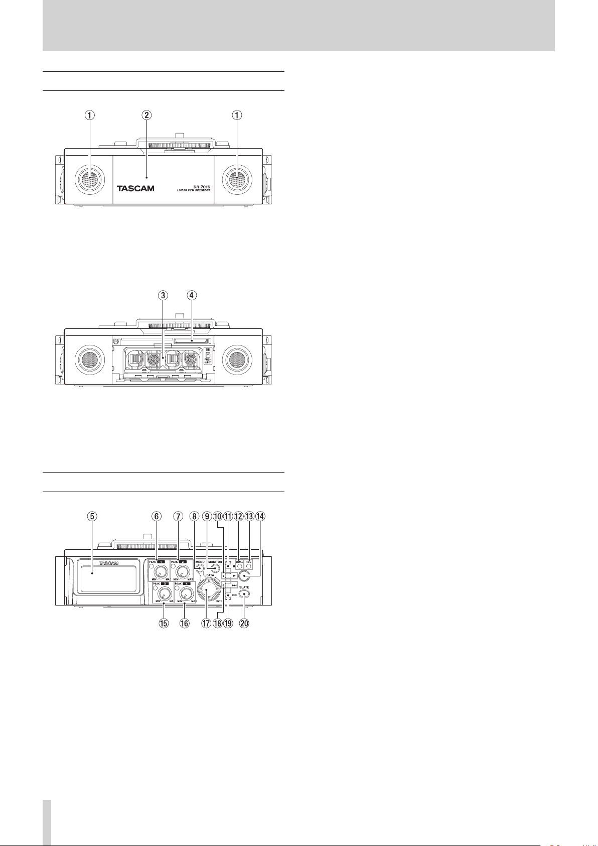
Front panel
1 Built-in stereo microphone
This stereo microphone uses two omnidirectional electret
condenser mics.
2 Front cover
This covers the battery compartment and the SD slot.
7 2 knob and PEAK indicator
Use the 2 knob to adjust the input level from the IN 2
connector on the left side of the unit.
The 2 PEAK indicator lights when the input level is about to
cause distortion.
During mic input, this also lights if distortion occurs in
the analog circuitry. During line level input, this does not
light even if distortion occurs in the analog circuitry.(see
“Adjusting the input level” on page 20)
8 MENU button
When the Home Screen is open, press this button to open
the Menu Screen.
When a setting screen is open, press to move up one level in
the menu. When the Menu Screen is open, press to return to
the Home Screen.
9 MONITOR button
When not playing back, press to open the monitoring source
selection menu.
0 2/7 button
When the Home Screen is open and the unit is stopped,
press this button to start playback.
When a file or folder is selected on the Browse Screen, press
this button to return to the Home Screen and play the file or
the first file in the folder from the beginning.
Press this button when a
menu page is shown to move the cursor to the channel 2
setting.
CH1/CH2/CH3/CH4
item on a
3 Battery compartment
Install batteries (4 AA) in this compartment to power the
unit.(see “Using AA batteries” on page 13)
4 SD card slot
Insert an SD card here.
Rear panel
5 Display
This shows a variety of information.
6 1 knob and PEAK indicator
Use the 1 knob to adjust the input level from the IN 1
connector on the left side of the unit.
The 1 PEAK indicator lights when the input level is about to
cause distortion.
During mic input, this also lights if distortion occurs in
the analog circuitry. During line level input, this does not
light even if distortion occurs in the analog circuitry.(see
“Adjusting the input level” on page 20)
q 1/8 button
Press this button during playback to stop playback and
return to the beginning of that playback file.
Press this button during recording to stop recording.
Press this button when a
menu page is shown to move the cursor to the channel 1
setting.
Use this button to answer “NO” to a confirmation message
when using a setting screen.
CH1/CH2/CH3/CH4
item on a
w DUAL indicator
This lights orange when in dual recording mode.
e REC indicator
This lights red when recording.
r Record (0) button
Press when stopped to start recording.
t 3 knob and PEAK indicator
Use the 3 knob to adjust the input level from the IN 3
connector on the left side of the unit.
The 3 PEAK indicator lights when the input level is about
to cause distortion. During mic input, this also lights if
distortion occurs in the analog circuitry. During line level
input, this does not light even if distortion occurs in the
analog circuitry.(see “Adjusting the input level” on page
20)
y 4 knob and PEAK indicator
Use the 4 knob to adjust the input level from the IN 4
connector on the right side of the unit.
The 4 PEAK indicator lights when the input level is about
to cause distortion. During mic input, this also lights if
distortion occurs in the analog circuitry. During line level
input, this does not light even if distortion occurs in the
analog circuitry.(see “Adjusting the input level” on page
20)
TASCAM DR-701D
6
2 – Names and functions of parts
u DATA dial (ENTER)
Turn to select items and change values on setting screens.
Push to confirm selections on setting screens and to answer
“YES” to confirmation pop-up messages.
Press during recording to add a mark manually.(see “Using
mark functions” on page 27)
i 3// button
Press this button during playback or when stopped to move
to the next mark. When there are no marks, press to skip to
the next file.
Press and hold this button to search forward.
Press this button when a
menu page is shown to move the cursor to the channel 3
setting.
On the setting screens, use this button to move the cursor
right.
If a file is selected, the file is loaded and the unit returns to
the Home Screen.
CH1/CH2/CH3/CH4
item on a
o 4/. button
Press this button to move to the previous mark during
playback or when stopped in the middle of a file. When
there are no marks, press to return to the beginning of the
playback file.
If you press this button when a file is stopped at its
beginning, the unit will skip to the beginning of the previous
file.
Press and hold this button to search backwards.
Press this button when a
menu page is shown to move the cursor to the channel 4
setting.
On the setting screens, use this button to move the cursor
left.
CH1/CH2/CH3/CH4
item on a
p SLATE button
Press and hold during recording, playback or monitoring
to record a slate stone.(see “Recording slate tones” on page
28)
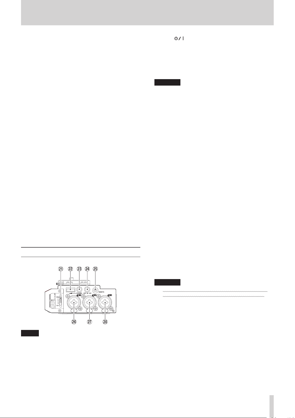
a HOLD/ switch
Slide this switch down (in the direction of the arrow) to turn
the unit on/off.
Set it to the top position to activate the hold function. All
buttons are inoperative when hold is ON.
s PHONES volume
Use to adjust the volume output from the PHONES jack.
CAUTION
Before connecting headphones, lower the PHONES volume
to the minimum level. Failure to do so could result in a
sudden loud noise that could harm hearing, for example.
d PHONES jack (3.5mm stereo mini jack)
Connect stereo headphones to this stereo mini jack.
Use the PHONES control to adjust the volume.
f EXT IN 1/2 connector (3.5mm stereo mini jack)
Use this input jack to connect a stereo mini jack mic or an
external device.
This jack provides plug-in power.
TRS (Tip: HOT, Ring: COLD, Sleeve: GND)
g REMOTE jack (2.5mm TRS jack)
Connect a TASCAM RC-3F footswitch or TASCAM RC-10
wired remote control (both sold separately) here. This
enables remote starting and stopping of playback and other
functions.(see “10 – Using the REMOTE jack” on page 39)
h IN 1 connector (XLR/TRS)
This balanced analog jack is an XLR mic and standard TRS
jack input.
XLR (1: GND, 2: HOT, 3: COLD)
TRS (Tip: HOT, Ring: COLD, Sleeve: GND)
j IN 2 connector (XLR/TRS)
This balanced analog jack is an XLR mic and standard TRS
jack input.
XLR (1: GND, 2: HOT, 3: COLD)
TRS (Tip: HOT, Ring: COLD, Sleeve: GND)
Left side
NOTE
When connecting and using plugs from external devices,
do not apply excessive force to the plugs. In particular,
be careful not to apply too much force when using a
standard to mini plug adapter. Doing so could damage the
equipment.
k IN 3 connector (XLR/TRS)
This balanced analog jack is an XLR mic and standard TRS
jack input.
XLR (1: GND, 2: HOT, 3: COLD)
TRS (Tip: HOT, Ring: COLD, Sleeve: GND)
CAUTION
•
Confirm that phantom power is OFF before connecting a
line level device to an IN 1, IN 2, IN 3 or IN 4 connector.
If you connect a line level device while phantom power is
being supplied, that device and this unit could be damaged.
•
When using a condenser microphone, before connecting to
or disconnecting from an IN 1, IN 2, IN 3 or IN 4 connector,
confirm that the phantom power for that jack is OFF. If you
connect or disconnect a mic while phantom power is being
supplied, that mic and this unit could be damaged.
•
Turn phantom power ON only when using a condenser
microphone that requires phantom power. Turning
phantom power on when a dynamic mic or other mic that
does not require it is connected could damage this unit and
connected equipment.
•
When using condenser mics that require phantom power
and dynamic mics together, be sure to use balanced
dynamic mics. Unbalanced dynamic mics cannot be used
when phantom power is enabled.
TASCAM DR-701D
7

2 – Names and functions of parts
Right side
NOTE
When connecting and using plugs from external devices,
do not apply excessive force to the plugs. In particular,
be careful not to apply too much force when using a
standard to mini plug adapter. Doing so could damage the
equipment.
l HDMI IN port
Connect a DSLR camera or other HDMI source device here.
; HDMI OUT port
Connect an HDMI monitor or other HDMI sync device here.
z Micro USB port
Use the included USB cable to connect with a computer USB
port.(see “8 – Connecting with a Computer” on page 35)
Power can be supplied through the USB cable provided with
the unit or a TASCAM PS-P515U AC adapter (sold separately).
CAUTION
The unit should be connected directly to the computer, not
through a USB hub.
n TIME CODE IN connector
Use a BNC cable to connect this with the time code output
connector of an external device.(see “Connecting a time
code generator” on page 17)
Top
m DSLR camera attachment bracket
Use this bracket, which is preinstalled on the unit, with the
DSLR mounting screw.
If you do not want to use this bracket, use a coin or other
tool to remove the four attachment screws.
, DSLR camera mounting screw (1/4-inch)
Use to attach this unit to the bottom of a camera or a rack
that supports camera mounting screws, for example.
x IN 4 connector (XLR/TRS)
This balanced analog jack is an XLR mic and standard TRS
jack input.
XLR (1: GND, 2: HOT, 3: COLD)
TRS (Tip: HOT, Ring: COLD, Sleeve: GND)
c IN connector (3.5mm stereo mini jack)
Use a stereo mini jack cable to connect this with the camera
audio output jack.
Refer to the camera’s operation manual to identify
connectors on the camera.(see “Camera connections” on
page 16)
v OUT jack (3.5mm stereo mini jack)
Use a stereo mini jack cable to connect this with the camera
external input jack.
Use the
the volume output from this jack.(see “Adjusting the
playback volume” on page 18)
Refer to the camera’s operation manual to identify
connectors on the camera.(see “Camera connections” on
page 16)
OUTPUT LEVEL
page
CAMERA
item to adjust
b LINE OUT jack (3.5mm stereo mini jack)
Use a stereo mini jack cable to connect this with the line
input jack of an external device.
Use the
volume output from this jack.(see “Adjusting the playback
volume” on page 18)
OUTPUT LEVEL
page
LINE
item to adjust the
. Accessory shoe
You can remove the included DSLR camera attachment
bracket to use the accessory shoe.
TASCAM DR-701D
8
2 – Names and functions of parts
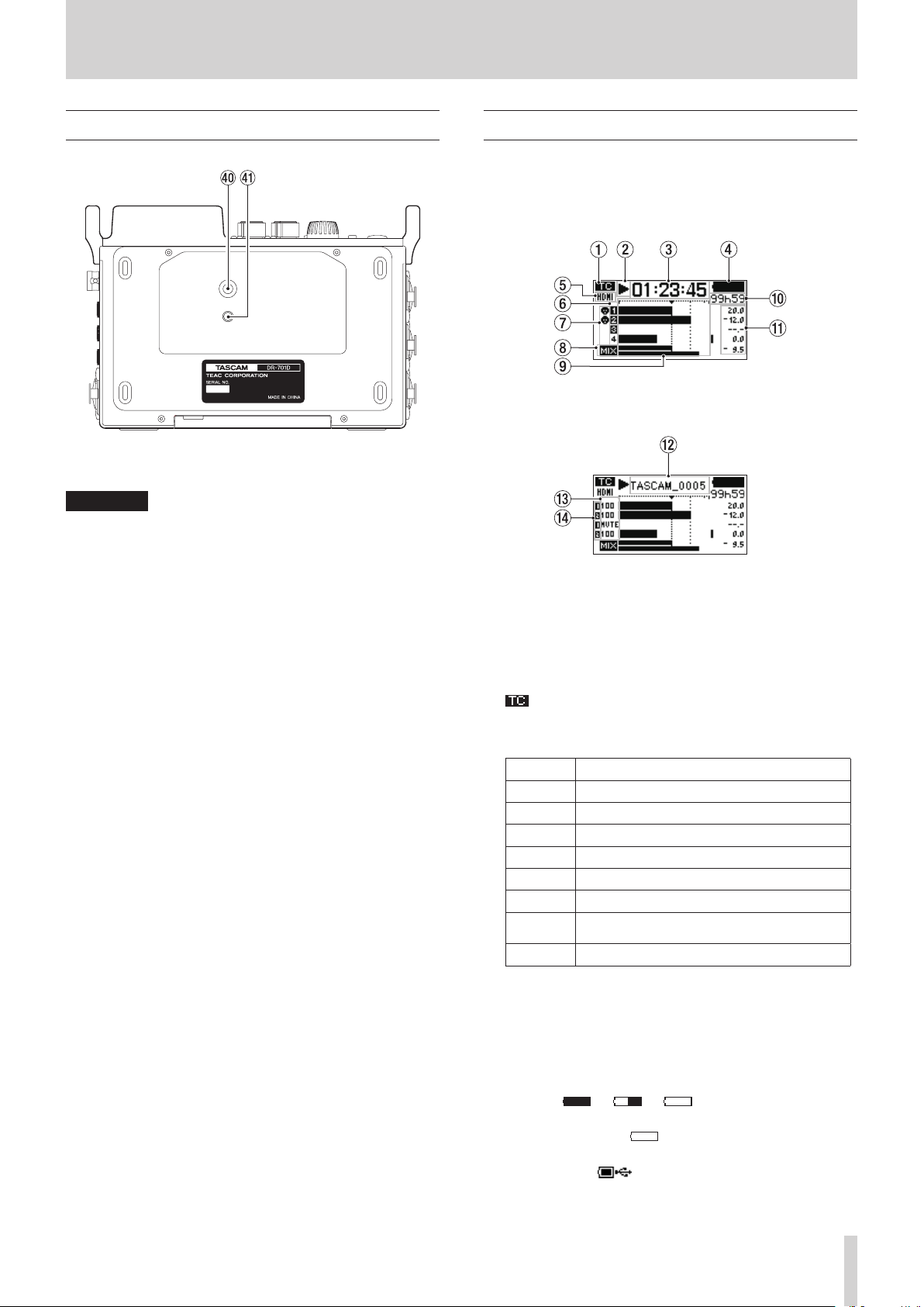
Bottom
/ Tripod mounting threads (1/4-inch)
Use to attach this unit to a tripod.
CAUTION
•
Securely tighten all the screws on the tripod or microphone
stand to prevent the unit from falling off.
•
Place the tripod or microphone stand on a level surface
when using it with this unit.
•
Some tripods have different screw specifications that make
direct connection impossible. Use a commercially-available
adapter with such tripods.
! Video camera pin hole
When using a tripod with a pin for video cameras, align this
hole with the pin when attaching the unit to the tripod.
Home Screen
The unit's Home Screen has a counter display mode and a trim
display mode.
When the Home Screen is open, press the DATA dial to change
the display mode.
Home Screen counter display mode
Home Screen trim display mode
1 Time code reception status
This shows the time code reception status.(see “Inputting
time code and adding recording start times to files” on page
28)
No indicator: time code not being received
: time code being received
2 Recorder operation status
This icon shows the recorder operation status.
Indicator Meaning
8
9
7
,
m
/
.
0
Stopped
Paused
Playing back
Searching forward
Searching backward
Skipping to the beginning of the next file
Skipping to the beginning of the current or
previous file
Recording
3 Elapsed time
This shows the elapsed time (hours: minutes: seconds) of the
current file.
4 Power supply status
A battery icon appears when power is supplied by batteries.
The icon shows the amount of battery power remaining with
25 levels ( e e ).
The battery is almost dead and the unit will soon turn off
(enter standby) if the icon appears empty and blinks.
When using the PS-P515U AC adapter (sold separately) or
USB bus power, appears. Even when using bus power,
you can check the unit's remaining battery power with an
8-level indicator.
TASCAM DR-701D
9
2 – Names and functions of parts
NOTE
Sometimes a
recording or conducting other demanding operations even
when battery power remains.
Batte y Lo
warning appears when
5 HDMI connection status
This shows the HDMI connection status.
No indicator: ; HDMI not connected
: HDMI connected
: HDMI connected (clock sync)
6 Recording setting status
These show whether or not recording is enabled. (see
“Setting channels to record” on page 25)
: recording not enabled
: recording enabled
7 Phantom power status
These show whether phantom power is on or off.(see
“Setting phantom power” on page 22)
No icon: Phantom power off
: Phantom power on
8 MIX recording setting status
: MIX recording off
: MIX recording on
9 Level meters
These show the levels of the input and playback signals.
The dotted lines at the −20dB (b mark) and −12dB
positions are guides for input level adjustment.
0 Remaining time
When playing back, this shows the remaining time (hours:
minutes) of the current file.
When recording, this shows the remaining time (hours:
minutes) of the SD card.
q Peak values in decibels (dB)
During playback, the maximum level that occurs in a fixed
period of time is shown in decibels for each channel.
During recording, the peak input level values are shown in
decibels.
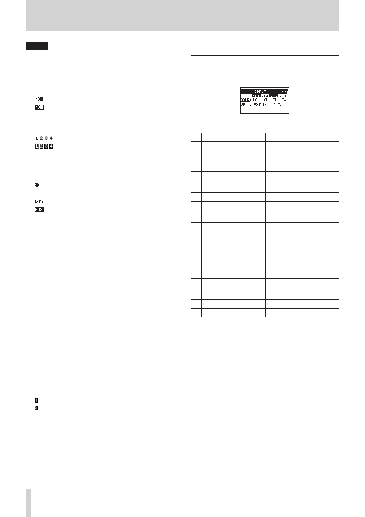
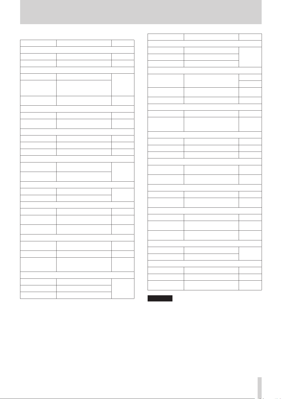
Menu structure
The first time, press the MENU button to open the
of the menu. In the future, press this button to reopen the menu
page that was last open.
The Menu Screen has 18 pages organized by types of menu
items.
Page name Meaning
INPUT
1
MIXER
2
PHASE/DELAY
3
LEVEL CONTROL
4
TRIM GANG
5
OUTPUT LEVEL
6
MIC POWER
7
RECORD
8
REC SETTING
9
FILE
10
MEDIA
11
TIME CODE
12
SLATE TONE
13
HDMI AUDIO
14
ASSIGN
METER/TRIM
15
POWER MANAGEMENT
16
REMOTE
17
SYSTEM
18
Make input settings.
Make built-in mixer settings.
Make input phase settings and
compensate for mic distances.
Make input level settings.
Make GANG operation
settings.
Make output level settings.
Make mic power settings.
Make recording channel
settings.
Make recording settings.
Make file settings.
Make media settings.
Make time code settings.
Make slate tone settings.
Set HDMI output audio assign-
ments.
Make meter and trim settings.
Make power management
settings.
Make remote control settings.
Make system settings.
INPUT
page
w Project name
This shows the name of the project being recorded or
playing back.
A project is a group of files used for recording/playback.
e Trim values
These show the settings of the 1/2/3/4 knobs.
r GANG status
These show the GANG operation status of the 1/2/3/4
knobs (see “Setting the GANG operation mode” on page
34)
: Set to GANG group 1
: Set to GANG group 2
TASCAM DR-701D
10
2 – Names and functions of parts
The various menu items are as follows.
Menu item Function Page
INPUT page
GAIN
SEL
Set the input gain. page 20
Select input sources. page 20
MIXER page
LVL.
Adjust the level.
PAN
Adjust the left/right balance.
Adjust the mid/side balance
page 34
in mid-side mode.
MS
Turn mid-side decoding on/
off.
page 34
PHASE/DELAY page
PHAS
DELY
Set the input phase. page 21
Compensate for mic
distances.
page 21
LEVEL CONTROL page
LIM. Set the limiter. page 23
AUTO
LCF
Set automatic level control. page 24
Set the low-cut filter. page 24
TRIM GANG page
GRP1
GRP2
Set the group 1 GANG
operation.
Set the group 2 GANG
operation.
page 34
OUTPUT LEVEL page
CAMERA
LINE
Set the camera output level.
Set the line output level.
page 18
MIC POWER page
PHAN
VOLTAGE
PLUGIN
Turn phantom power on/off. page 22
Set the phantom power
voltage.
Set the plug-in power
function.
page 22
page 23
RECORD page
SEL
MIX
Make recording channel
settings.
page 25
Make MIX recording settings. page 25
Make channel settings
DUAL
and adjust levels for dual
page 26
recording.
REC SETTING page
FILE TYPE
FORMAT
SAMPLE
Set the recording file type.
Set the recording file format.
Set the sampling frequency.
page 24
Menu item Function Page
FILE page
NAME TYPE
WORD
COUNT INIT
Set the file name format.
Set the file name text.
Reset the file number.
page 36
MEDIA page
BROWSE
NEW FOLDER
FORMAT
Work with files and folders on
the SD card.
Make settings for new folder
creation.
Format SD cards. page 36
page 31
page 32
page 32
TIME CODE page
SELECT
POWER OFF
GEN
Set the time code source. page 28
Set whether or not the
generator runs when the
page 29
power is off.
SLATE TONE page
AUTO
VOLUME
OSCILLATOR
Set the automatic slate tone. page 27
Set the slate tone volume. page 27
Activate the oscillator. page 27
HDMI AUDIO ASSIGN page
SEL
MIX
Make HDMI output channel
settings.
Make HDMI output MIX
setting.
page 29
page 29
METER/TRIM page
PEAK HOLD
TRIM MIN
Set the peak hold time. page 37
Make the trim operation mute
setting.
page 37
POWER MANAGEMENT page
BATTERY TYPE
AUTO PWR
SAVE
BACKLIGHT
Set the type of batteries. page 37
Set the automatic power off
function.
Set the time until the
backlight turns off.
page 37
page 37
REMOTE page
CONTROLLER
MODE
Make remote control settings.
Set the remote control mode.
page 39
SYSTEM page
INITIALIZE
DATE/TIME
INFORMATION
Restore the default settings. page 37
Set the date and time. page 15
Shows a variety of infor-
mation.
page 38
CAUTION
•
During recording, the menu pages from
OUTPUT LEVEL
will be shown. The
later menu pages will not be shown.
•
The settings for all menu items are retained even when the
unit is turned off.
INPUT
MIC POWER
to
and
TASCAM DR-701D
11
2 – Names and functions of parts
Basic Menu Screen operations
Use the following operations to work with the pages of the
Menu Screen.
Selecting items (moving vertically on a page):
8
Turn the DATA dial.
NOTE
Turn the DATA dial to move up or down one item at a time
from the
INFORMATION
Confirming a selected item:
8
Press the DATA dial.
Opening a submenu from a page:
8
Press the DATA dial.
Going back one level in a menu:
8
Press the MENU button.
Returning to the Home Screen from a menu:
8
Press the MENU button.
Menu operation procedures
In this example, we explain how to change recording settings.
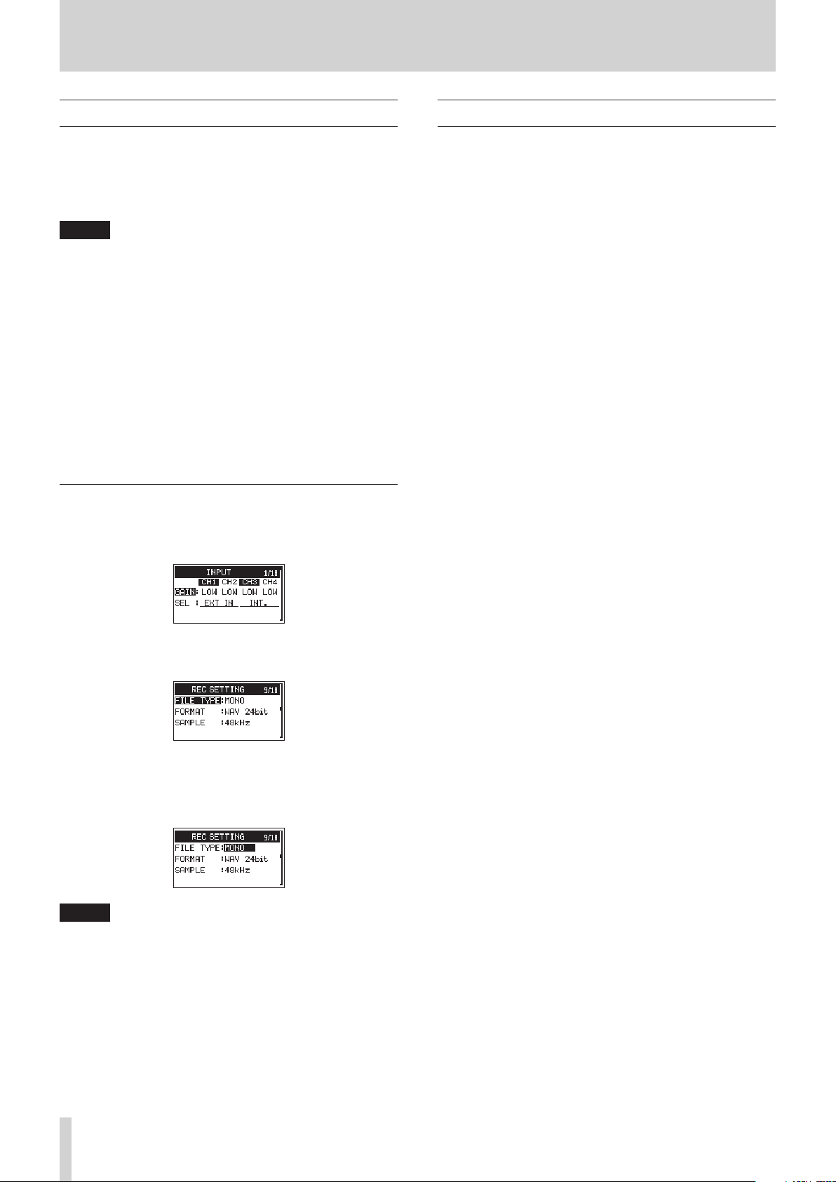
1. Press the MENU button to open the Menu Screen.
INPUT
page
item.
GAIN
item to the
SYSTEM
page
Basic operation
Use the following buttons to operate the various screens.
MENU button
8
This opens the Menu Screen.
1/8 button
8
Press this to answer “NO” to a pop-up confirmation message.
DATA dial
8
Turn the DATA dial to select items and change values on setting
screens. You can also turn the DATA dial to change the file
playback position.
Push the DATA dial to confirm selections on setting screens and
to answer “YES” to confirmation pop-up messages.
3// button
8
On the Browse Screen, use this to advance a level.
4/. button
8
On the Browse Screen, use this to go back a level.
2. Turn the DATA dial to select an item (highlighted) to be set
on a menu page.
REC SETTING
3. Press the DATA dial to move the cursor to (highlight) the
value of the setting.
page
FILE TYPE
item selected
NOTE
For a setting item that shows CH1/CH2/CH3/CH4, press the
DATA dial to move the cursor to the setting value of the next
channel in order. In addition, pressing a number button will
also move the cursor to the corresponding channel.
4. Turn the DATA dial to change the setting.
5. Press the DATA dial or MENU button to set a different item.
This enables selection of a different item. Turn the DATA dial
to select an item to be set.
6. Repeat steps 3 to 6 as necessary to set other items.
7. Press the MENU button to return to the Home Screen.
TASCAM DR-701D
12

3 – Preparation
Powering the unit
Power sources
This unit can be powered by 4 AA batteries or by using the
included USB cable to supply USB bus power. The USB cable
can also be connected to a TASCAM PS-P515U AC adapter or a
TASCAM BP-6AA external battery box (both sold separately).
This unit can use alkaline, Ni-MH or lithium AA batteries.
Using AA batteries
Open the front cover and battery compartment. Install 4 AA
batteries in the compartment with the ¥ and ^ marks as
shown. Then, close the battery compartment and front cover.
Using an AC adapter (sold separately)
Use the included USB cable to connect the TASCAM PS-P515U
AC adapter to the unit's USB port as shown in the illustration.
AC outlet
TASCAM
PS-P515U (sold separately)
NOTE
When both batteries are installed and the AC adapter is
connected, power will be supplied from the AC adapter.
CAUTION
•
Never use any adapter other than the designated TASCAM
PS- P515U AC adapter. Use of a different adapter could
cause malfunction, fire or electric shock.
•
Noise may occur when recording with a microphone if the
unit is too close to the AC adapter. In such a case, keep sufficient distance between the AC adapter and the unit.
Connect the
included USB cable
micro-B USB plug
When using AA batteries, set the type of battery in order to
accurately show the amount of power remaining and allow the
unit to accurately determine whether power is available for
proper operation.(see “Setting the type of batteries” on page
37)
CAUTION
•
Manganese dry cell batteries cannot be used with this unit.
•
This unit cannot recharge Ni-MH batteries. Use a commercially available recharger.
NOTE
A great amount of power is required to provide phantom
power to a condenser microphone. If you use a condenser
microphone while running the unit on AA batteries
((alkaline, NiMH or lithium), the operation time will be
shortened.
If you need to operate the unit for a long time, use a TASCAM
PS-P515U AC adapter or TASCAM BP-6AA external battery
box (both sold separately) to power the unit.
Using an external battery pack (sold
separately)
Connect a TASCAM BP-6AA external battery pack (designed for
use with this unit and sold separately) to the recorder with the
included USB cable as shown in the illustration. For details, see
the BP-6AA Owner’s Manual.
TASCAM BP-6AA (sold separately)
Connect the included USB
cable
micro-B USB plug
CAUTION
The unit cannot detect the remaining battery charge of a
BP-6AA. If you use a BP-6AA to operate the recorder without
batteries in the unit itself, it might stop operating suddenly
if the battery pack runs out of charge.
In order to avoid problems, put batteries with sufficient
charge into the unit before connecting and using a BP-6AA.
TASCAM DR-701D
13
3 – Preparation
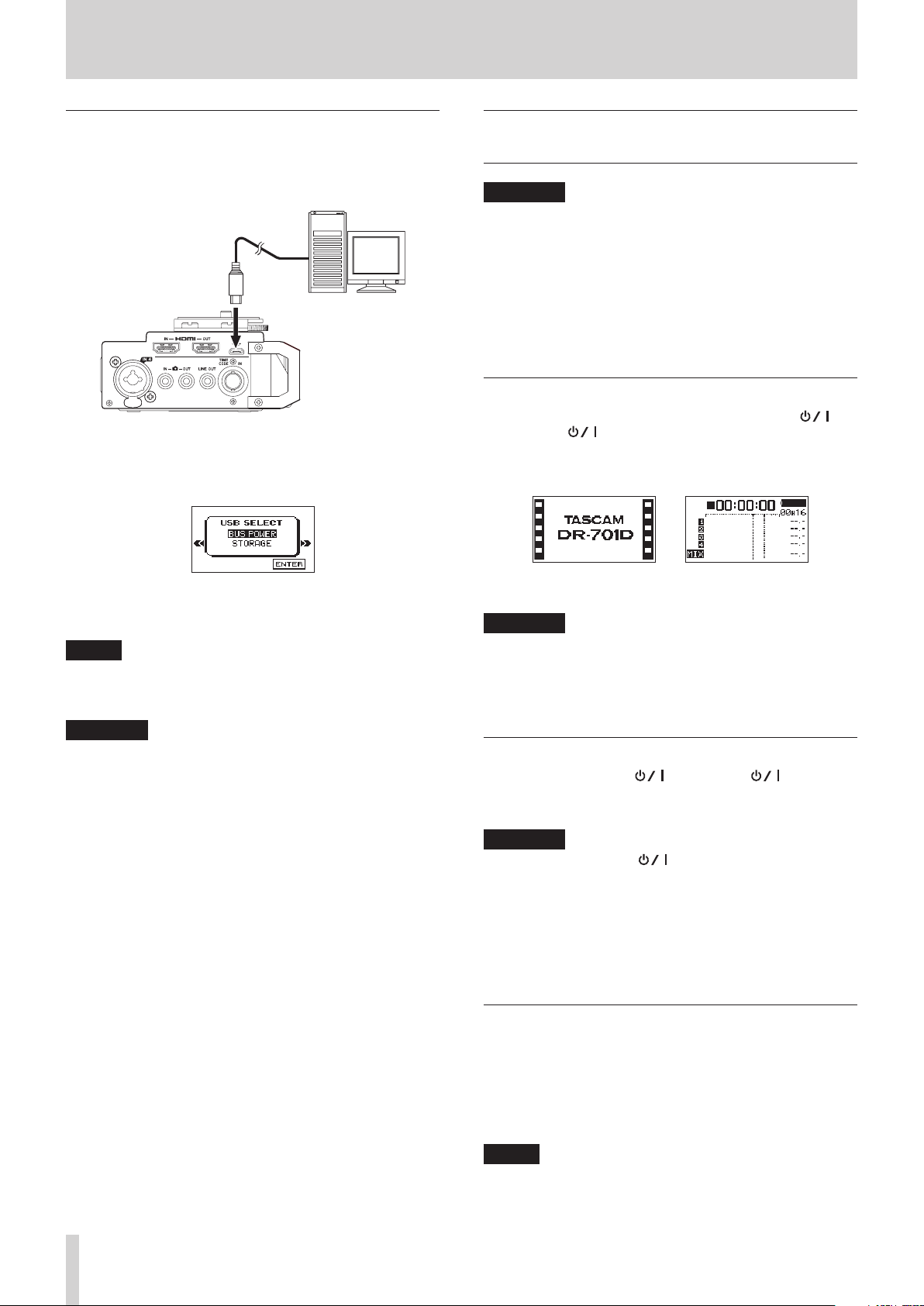
Using USB bus power
Connect the unit to a computer using the included USB cable as
shown in the illustration.
Computer
Connect the included USB cable
micro-B USB plug
If the USB cable is connected while the unit is on or the unit
is turned on with the USB cable already connected, the
SELECT
supply or computer connection on this screen.
screen will appear. Choose between USB bus power
USB
Turning the power on and off (putting
it in standby)
CAUTION
•
The unit enters standby mode if shut down when the unit
is operating on AC power supplied through a TASCAM
PS-P515U AC adapter (sold separately) or bus power
supplied from a computer USB port.
•
Turn down the volume of the monitoring system connected
to the unit before turning the unit on/off (standby).
•
Do not use headphones when turning the unit on/off
(standby). Loud noises could damage the speakers or harm
your hearing.
Turning the unit on
To start the unit when off (in standby), slide the HOLD/
switch toward until "TASCAM DR-701D" (start-up screen)
appears on the display.
The Home Screen appears after the unit starts up.
Turn the DATA dial to select
dial to enable power supply from the USB port. The Home
Screen will appear.
BUS POWER
and press the DATA
NOTE
Power is supplied from the USB port if the USB cable is
connected to the unit even when it contains batteries (USB
bus power prioritized).
CAUTION
•
Depending on the USB bus power specifications of the
computer, this unit might not function when connected
to the computer by USB cable. In this case, use a TASCAM
PS-P515U AC adapter (sold separately) or batteries.
•
This unit does not support computer power conservation
and sleep functions. When powering the unit using the USB
bus power of a computer, always turn such functions off.
Start-up Screen Home Screen
CAUTION
When the unit is started up for the first time (or when
the built-in clock is reset after being left unused without
batteries), the
Start-up Screen so you can set the date and time.(see
“Setting the date and time” on page 15)
DATE/TIME
screen appears before the
Turning the unit off (putting it in standby)
When on, slide the HOLD/ switch toward .
The unit turns off (enters standby) after it completes its
shutdown process.
CAUTION
Always use the HOLD/ button to turn the unit off (put it
in standby).
While the unit is on, do not remove the batteries, disconnect
the power cord when using a TASCAM PS-P515U AC adapter
(sold separately) or disconnect the USB cable when using
USB bus power. Doing so will cause all recordings, settings
and other data to be lost. Lost data and settings cannot be
restored.
Resume function
This unit has a resume function. When started up, the unit
locates to the position (time) where it was when turned off (put
in standby) previously.
After the unit is turned on, playback is possible from the
position (time) it was at when the 2/7 button was pressed to
turn the unit off (put it in standby).
TASCAM DR-701D
14
NOTE
This data is stored on the SD card. The resume function will
not work if the card is changed or formatted.
 Loading...