

TAND B ER G
Telepresence T3
Note that the
door is not a part
of the Immersive
Room Package and
that the door should open
outwards.
This document is confidential and remains proprietary
to TANDBERG Telecom AS (“TANDBERG”).
Without TANDBERG’s prior written approval, this
document, either in whole or in part, may not be
reproduced in any form or by any means, disclosed
to others outside the Client’s organisation or used for
any purpose whatsoever other than for evaluatory
purposes by the Client.
All information, descriptions, examples and
calculations contained in this document are for
guidance purposes only and should not be treated as
definitive.
Whilst all reasonable care has been taken to ensure
that the information contained in the presentation is
accurate and not misleading, TANDBERG shall not be
liable for any loss resulting from reliance placed on the
information contained in this document.
TANDBERG WORLD HEADQUARTERS
Philip Pedersens vei 20
1366 Lysaker, Norway
Tel: +47 67 125 125
Fax: +47 67 125 234
Video: +47 67 126 126
E-mail: tandberg@tandberg.com
1212 Avenue of the Americas
24th Floor
New York, NY U.S.A. 10036
Tel: +1 212 692 6500
Fax: +1 212 692 6501
Video: +1 212 692 6535
E-mail: tandberg@tandberg.com
www.tandberg.com
119076.02 TELEPRESENCE T3 ROOM REQUIREMENTS 12.08
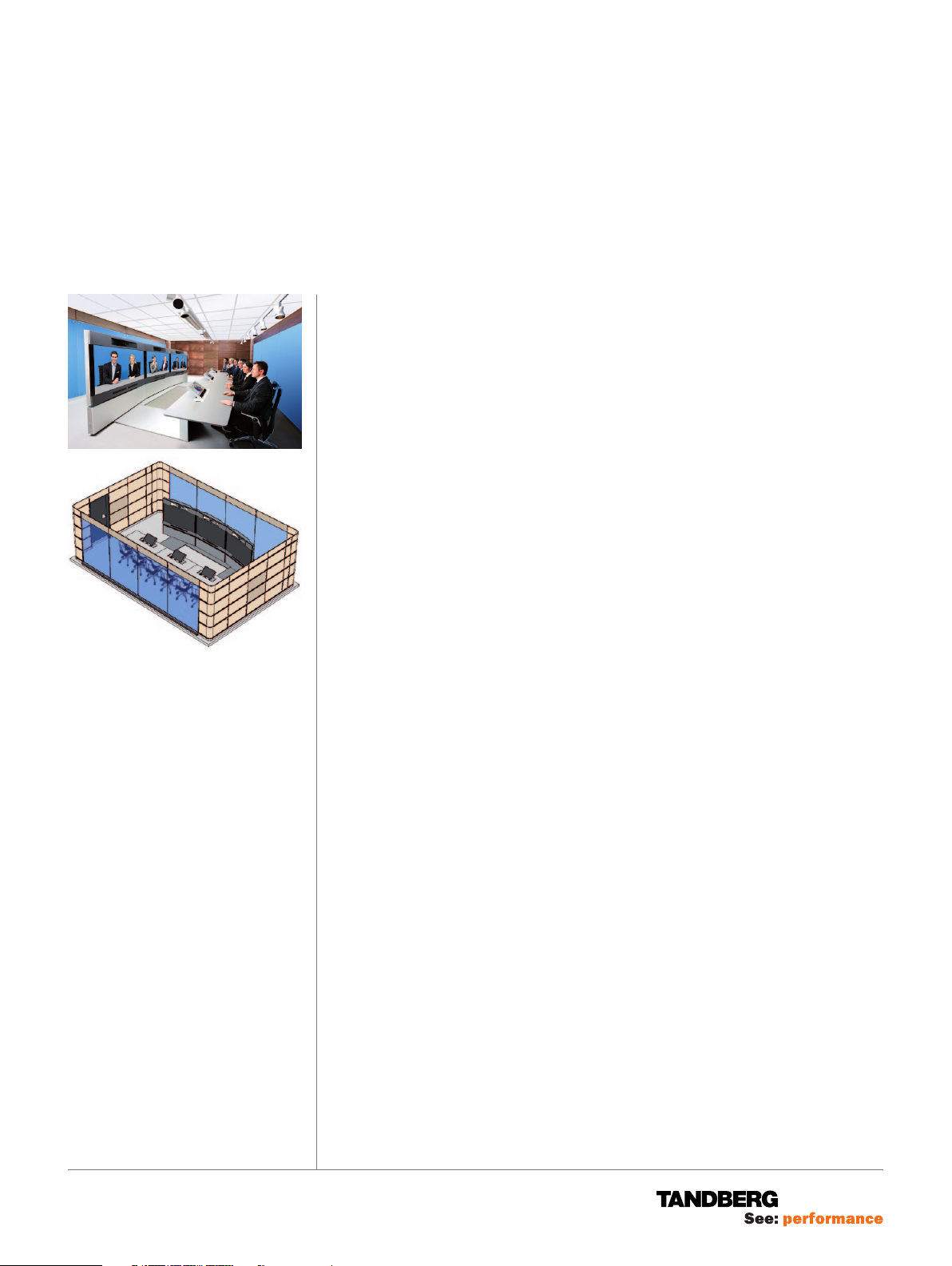
ROO M REQ UIREM ENTS
The Room Requirements Description presents the room dimensions
requirements, weights, wall- and ceiling loads, power outlet requirements as
well as the heating, ventilation and air-conditioning (HVAC) requirements for the
TANDBERG Telepresence T3 system.
Independent of whether customers plan to install a TANDBERG Immersive
Room, or create their own, this document is important to read.
Note that the entrance door is not a part of the TANDBERG Immersive Room
package. The door should open outwards.
ROOM DIMENSIONS
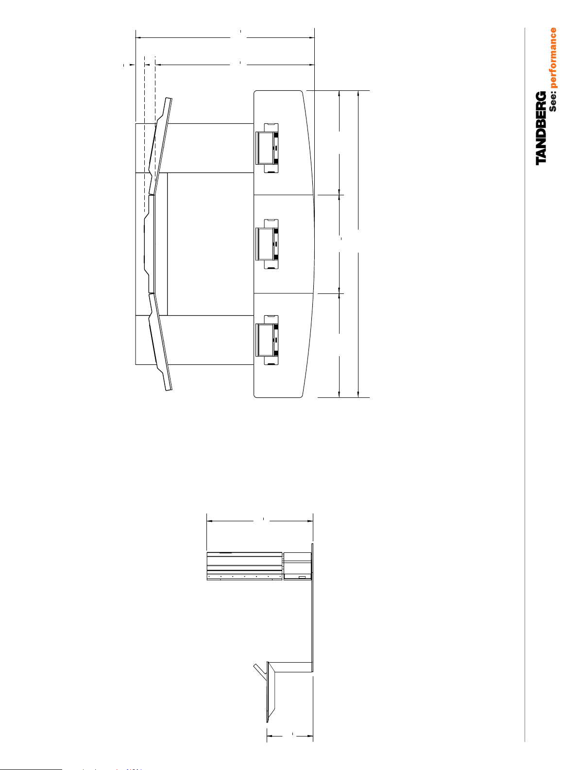
Overall system dimensions:
2800 mm × 4800 mm / 9’ 2 1⁄4”× 15’ 9” (d × w)
Optimal room dimensions (immersive room):
4680 mm × 7170 mm / 15’ 4
Room Height: 2550 mm / 8’ 4
WEIGHT AND LOAD REQUIREMENTS
Weight of total system: 1.075 kg
Weight of Wooden Wall panels: 15 kg / m2 (0.021lbs/inch2)
Weight of Glass Wall Panels: 60 kg (132 lbs)
The Floor load for the glass panels: 240 kg (528 lbs) / 8 adjustable legs
(A = 314 mm2) 0.76 kg/mm2 (135 lbs/inch2)
Wall Load for sidewalls: (for maximum size room)
Wall load for front / back wall (3.9 m
Wall Load for side wall (11.47 m
Ceiling Load:
Ceiling lights: 42 kg (92 lbs)
Document camera: 12 kg (26 lbs)
CONTENTS
Room requirements ................................................................................................1
System dimensions ................................................................................................ 2
Room depth requirements optimal and maximal depth .........................................3
Minimum room depth requirements ......................................................................4
Minimum room width requirements ......................................................................5
Optimum and maximum room height ....................................................................6
Minimum room height requirements .....................................................................7
Maximum room height ...........................................................................................8
HVAC requirements ................................................................................................9
Acoustics requirements ........................................................................................11
Power outlet fuse requirements ...........................................................................12
Electronic versions of Technical drawings ............................................................13
1
⁄4”× 23’ 6 1⁄4” (d × w)
3
⁄8”
2
): 15 × 3.9 = 58.5 kg (129 lbs)
2
): 15 × 11.47 =172 kg (378 lbs)
PA GE 1 / 22
TA N D B E RG
Telepresence T3
T3 system dimensions
1
2800
"
4
110
120
"
3
4
4
3
2500
"
8
65
"
65
1650
"
"
5
8
59
1500
4800
189
SYS TE M D IMENS IONS
1
1658
"
65
1650
"
4
65
TA N D B E RG
Telepresence T3
724
"
1
2
28
PA GE 2 / 22
119076.02 TELEPRESENCE T3 ROOM REQUIREMENTS 12.08
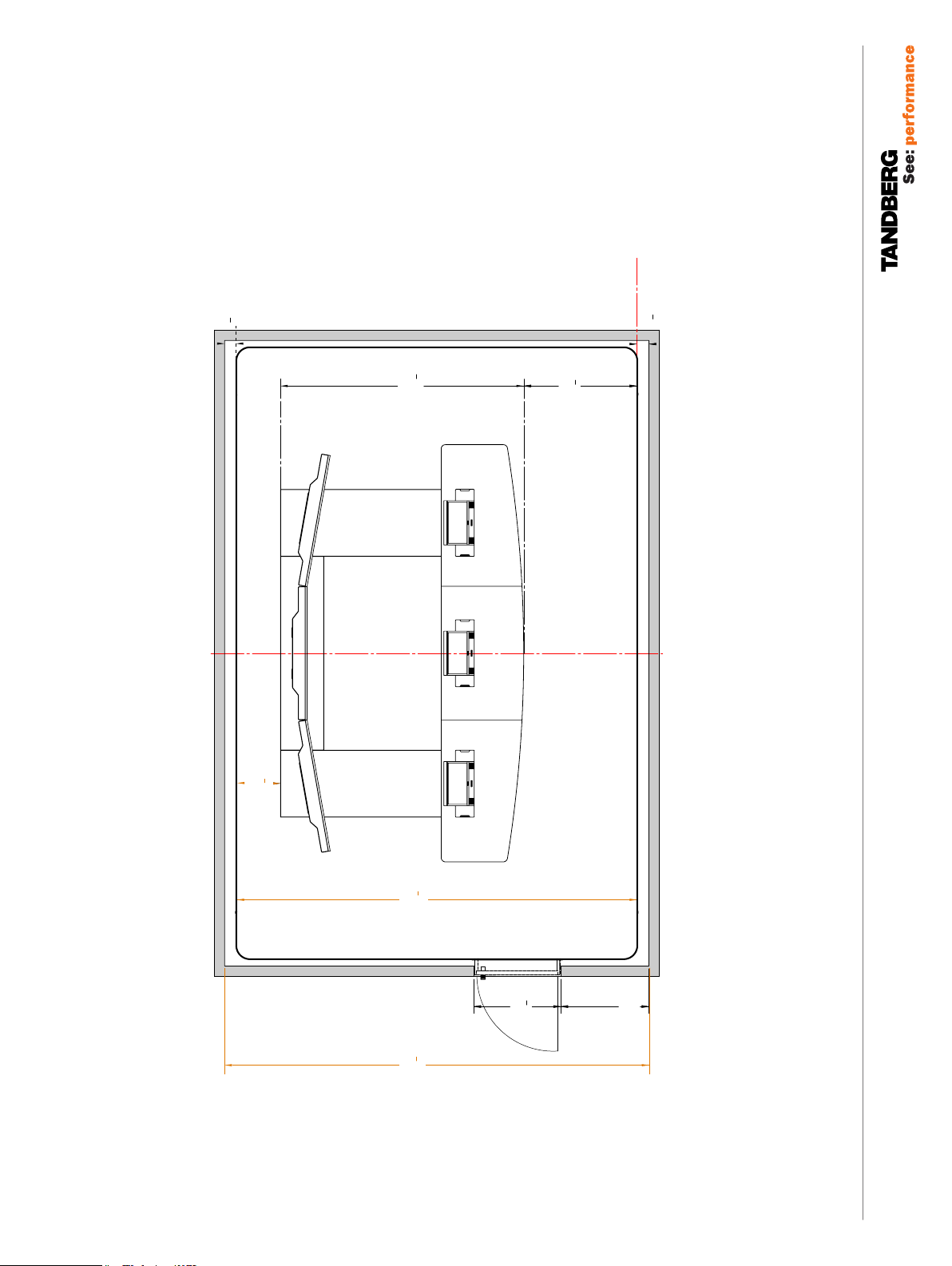
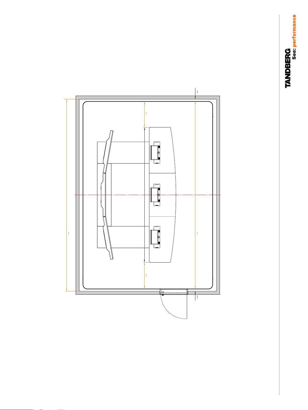
Optimal room depth
140
Centerline
Baseline
The 1300 mm is vital and should not be
exceeded. Otherwise the floor, the skirting
boards and the wooden panels start to become
"
1
2
5
"
1
4
110
2800
visible on the screen image.
"
1
8
51
1300
140
"
1
2
5
ROO M DEP TH RE QUIRE MENTS
OPT IM AL AND M AXIMA L DEP TH
TA N D B E RG
Telepresence T3
500
"
3
4
19
"
1
8
4600
181
"
3
1
4880
"
8
192
8
39
1000
1015
40"
PA GE 3 / 22
Note! The door is not a part of the TANDBERG Immersive Room
119076.02 TELEPRESENCE T3 ROOM REQUIREMENTS 12.08
Package. The door should be mounted so that it opens outwards.
TA N D B E RG
Telepresence T3
Baseline
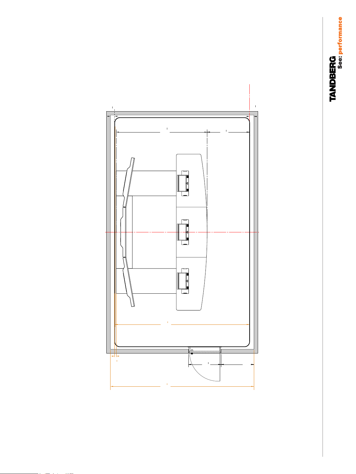
Min. room depth
140
Centerline
"
1
2
5
"
1
2800
4
110
1
1300
"
8
51
140
"
1
2
5
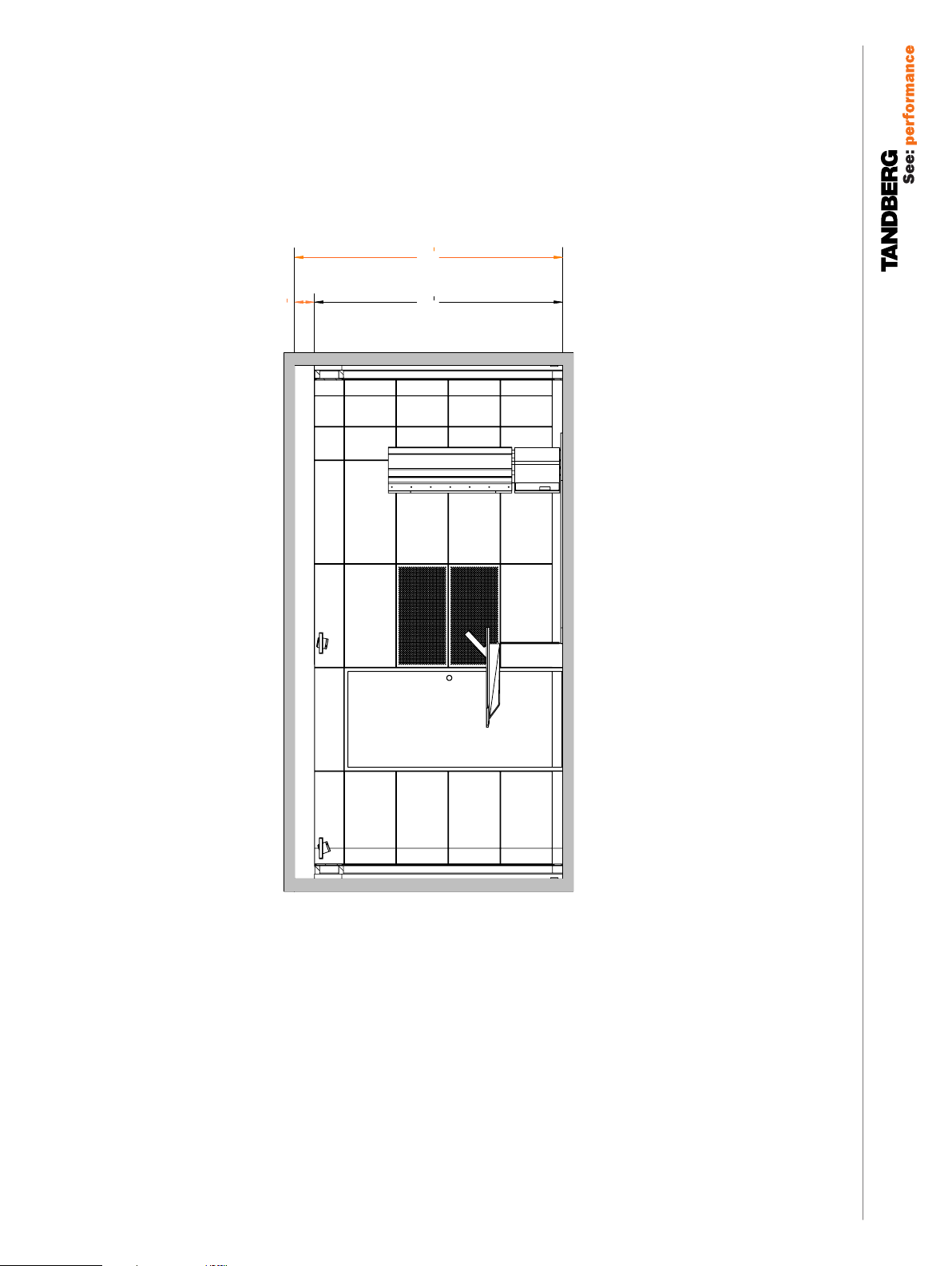
MIN IM UM ROOM DEPTH REQU IRE ME NTS
TA N D B E RG
Telepresence T3
"
1
4
4120
162
Observe that if the room gets smaller, the space between the table and backwall will be tight
"
3
4
20
"
1
4
4400
173
3
1000
"
8
39
1015
40"
PA GE 4 / 22
Note! The door is not a part of the TANDBERG Immersive Room
119076.02 TELEPRESENCE T3 ROOM REQUIREMENTS 12.08
Package. The door should be mounted so that it opens outwards.
Centerline
Min room width
3
922,5
4800
8
36 "
189 "
8
3
85
3 "
TA N D B E RG
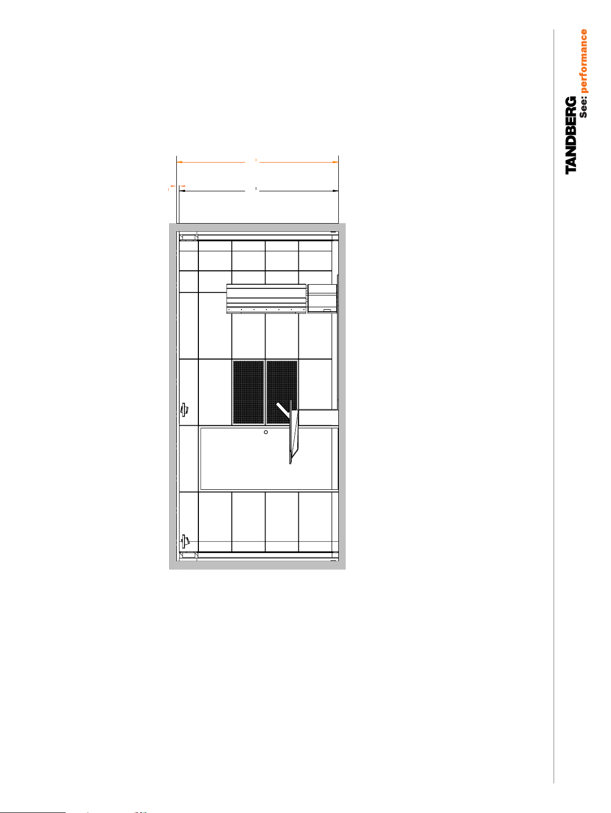
MIN IM UM ROOM WIDTH REQU IRE ME NTS
6815
4
1
268 "
3
922,5
8
36 "
5
6645
3
85
8
261 "
8
3 "
Observe that the room should not have a smaller width than shown
since that will prevent a proper installation of the wooden corner panels.
Telepresence T3
PA GE 5 / 22
Note! The door is not a part of the TANDBERG Immersive Room
119076.02 TELEPRESENCE T3 ROOM REQUIREMENTS 12.08
Package. The door should be mounted so that it opens outwards.
TA N D B E RG
Telepresence T3
190
optimal room height
"
8
3
2550
100
"
1
2
7
7
2360
"
8
92
OPT IM UM AND M AXIMU M ROO M H EI GHT
TA N D B E RG
Telepresence T3
Note that the room is shown with the Telepresence T3 system installed.
PA GE 6 / 22
119076.02 TELEPRESENCE T3 ROOM REQUIREMENTS 12.08
"
minimum room height
2
1
2400
94
"
5
8
1
40
7
2360
"
8
92
MI NI MUM ROOM HEIG HT RE QUI RE MEN TS
TA N D B E RG
Telepresence T3
Note that the room is shown with the Telepresence T3 system installed.
PA GE 7 / 22
119076.02 TELEPRESENCE T3 ROOM REQUIREMENTS 12.08

290
maximum room height
"
8
3
2650
104
"
3
8
11
7
2360
"
8
92
MAX IM UM ROOM HEIGH T
TA N D B E RG
Telepresence T3
Note that the room is shown with the Telepresence T3 system installed.
PA GE 8 / 22
119076.02 TELEPRESENCE T3 ROOM REQUIREMENTS 12.08

TA N D B E RG
Telepresence T3
Tip! An average person emits approximately
65 W at rest. You may want to consider this
when calculating the HVAC requirements.
Note: Dimensions are between floor and
underside of light modules.
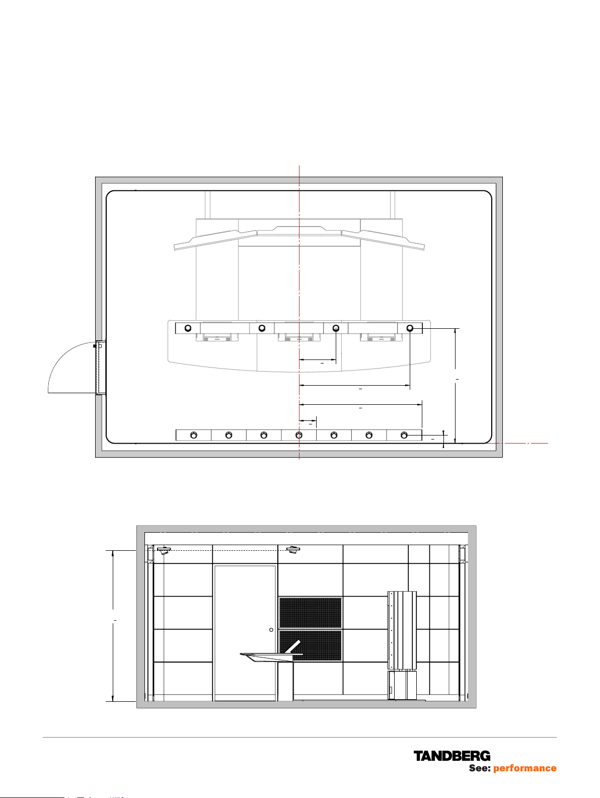
HVAC R EQ UIR EM ENT S
The following HVAC (heating, ventilation, air-conditioning) requirements apply to
the TANDBERG Telepresence T3:
• Power consumption System: 1725 W
• Power consumption Table: 300 W
• Power consumption Lighting: 1300 W
• Noise from air-conditioning should be less or equal to 27 dB(A) measured at
all seating positions.
Center line
Note: The HVAC equipment must not
be mounted in a way so that it prevents
correct mounting of the ceiling lights and the
document camera. Consult the TANDBERG
Telepresence T3 Room Installation Guide for
more on this.
119076.02 TELEPRESENCE T3 ROOM REQUIREMENTS 12.08
228 cm
7’53⁄4”
Make sure that HVAC mounting neither conflicts with the ceiling lights positions
nor the document camera position.
A detailed drawing of the ceiling mounting of the lights can be found overleaf,
while the drawing 119082 on page 14 shows the position of the document camera.
PA GE 9 / 22
TA N D B E RG
Telepresence T3
HVAC R EQ UIR EM ENT S
Centerline
675
5
"
26
320
12
8
2025
3
"
79
4
2247
1
"
88
2
5
"
8
150
5
2100
5
"
82
8
7
"
8
Baseline
Make sure that HVAC mounting neither conflicts with the ceiling lights positions nor the document
camera position. The drawing 119082 on page 14 shows the position of the document camera.
2280
3
89
"
4
119076.02 TELEPRESENCE T3 ROOM REQUIREMENTS 12.08
PA GE 1 0 /22

TA N D B E RG
Telepresence T3
ACO US TIC S REQ UIREM ENTS
It is essential to have a good acoustic environment for the system to provide the
true telepresence experience. This means that there should be sufficient sound
insulation to minimize noise from adjacent rooms and to ensure that confidential
information is kept within the meeting room. A good choice of acoustic materials
for the surfaces and low background noise will ensure comfort in long meetings
in addition to high speech intelligibility. You may want to contact acoustic
specialists when looking into this matter.
REQUIREMENTS IN GENERAL
All walls around the room should have a sound insulation of R’w ≥ 48 dB
(corresponding to STC 50).
The door should have a sound insulation of Rw ≥ 38 dB.
Background noise level should be less or equal to 30 dB(A). This includes both
noise from technical installations (air-conditioning in particular) and outdoor traffic
noise etc.
REQUIREMENTS SPECIFIC FOR IMMERSIVE ROOMS
Absorptive ceiling should have an absorption factor α≥ 0.9 in the octave bands
125–4000 [Hz]. This will normally require a mineral wool ceiling of good quality.
REQUIREMENTS SPECIFIC FOR NON-IMMERSIVE ROOMS
Reverberation time (RT) should be within 0.3–0.6 [s] in the octave bands
125–4000 [Hz].
The acoustic absorption should to some extent be distributed on the walls in
addition to the ceiling to avoid flutter-echo effects from parallel walls.
The ceiling is recommended to have an absorption factor ≥ 0.9 in the octave
bands 125–4000 [Hz]. This will normally require a mineral wool ceiling of good
quality.
The walls should at least have sound absorbing fields at the side, front and back
walls corresponding to the TANDBERG Immersive Room Package. Both the
placement and area should be approximately the same. If perforated or slotted
panels are used, the opening area of the panel must be at least 20
Sound absorption on walls could also be made with mineral wool wall panels,
curtains or other absorptive materials.
%.
119076.02 TELEPRESENCE T3 ROOM REQUIREMENTS 12.08
PA GE 1 1 /22

TA N D B E RG
POW ER OU TLET FUSE
Telepresence T3
Note! The table lists minimum fuse
requirements. All electrical work must
be done by electricians with local
knowledge.
Note! Outside the room—adjacent to the
entrance—there shall be an emergency
power switch to switch off the power to
the entire system and the room.
On the inside adjacent to the exit there
shall be a sign with the following text:
Fire emergency switch is
located on the outside of
this room.
REQ UI REM ENTS
The following minimum power outlet fuse requirements apply to the TANDBERG
Telepresence T3:
ITEM WATT PLACEMENT FUSE ON/OFF SWITCH
T1 Module × 3
Presentation
split ter × 2
Table power outlet × 6
TCU
Table quick buttons
Presentation input
switch
Touch collaboration
display splitter
Touch collaboration
display
Document camera
T3 Ceiling mounted
lights
T3 LED Module
2400 Back wall A 1
60 Back wall A 1
2400 Back wall B 2
400 Back wall C 2
50 Back wall C 2
5 Back wall C 2
20 Back wall C 2
750 Back wall C 2
300 Ceiling D 2
750 Ceiling D 3
1000 Back- / Front wall D 4
119076.02 TELEPRESENCE T3 ROOM REQUIREMENTS 12.08
Total power
933 5
PA GE 1 2 /22

TA N D B E RG
ELE CT RON IC VE RSION S OF
Telepresence T3
TEC HN ICA L DRAWI NGS
The technical drawings on the following pages are also available in electronic
formats as pdf, dwg and dxf. To obtain copies of these drawings, send an e-mail
to tandberg@tandberg.com
The following drawings are available:
• 119082 T3 Ceiling
• 119083 T3 Electrical System
• 119083-US T3 Electrical System US
• 119084 T3 Furniture Plan
• 119086 T3 Short Structure
• 119087 T3 Long Structure
• 119088 T3 Structural Elements
• 119089 T3 Lighting
119076.02 TELEPRESENCE T3 ROOM REQUIREMENTS 12.08
PA GE 1 3 /22

TANDBERG T3
01
A3
04.11.08
Sheet Size:
Date:
Related Tandberg Product -
www.tandberg.com
Revision:
Centerline
"
1
2
2100
82
2025
1
1000
"
39
"
1
2
79
2
"
1
2
1
1000
"
39
675
26
2
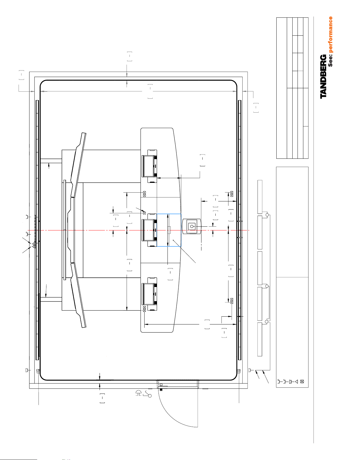
Area where installation of aircondition
should be avoided
Installation area for ceiling mounted document camera
(see separate installation guide)
No air condition in this area.
150
1
2247
"
88
6"
TANDBERG
"
1
2
2
320
12
194"
4930
T3 Ceiling
119082
Drw. No.:
Doc. Title:
Sign.:
1:25
Scale:
Unit: mm/"
88"
2240
PA GE 1 4 /22
Note! The door is not a part of the TANDBERG Immersive Room
119076.02 TELEPRESENCE T3 ROOM REQUIREMENTS 12.08
Package. The door should be mounted so that it opens outwards.
140
03
01.12.08
TANDBERG T3
02
"
3
8
85
3
"
1
2
5
"
1
8
4600
181
"
1
2
5
140
17.11.08
01
A3
04.11.08
Sheet Size:
Date:
Related Tandberg Product -
www.tandberg.com
Revision:
1:25
Scale:
119083
T3 Electrical System
:
4
On floor Cable Routing
A A B C
5
Video Lan
A A A B C
Customers Lan
On Floor Cable Routing
- Transport cables from T3
- Transport cables from T3
Power / AV / Lan
"
3
4
400
15
Centerline
Doc Cam Outlet
"
7
8
885
34
"
1
4
74
1885
760
"
1
2
570
22
"
5
8
829
32
"
"
7
Doc Cam location in
suspended ceiling
"
7
8
3
87,5
29
Doc Cam Capture Area
Max. size 760 x 570
Min. size 50 x 45
8
8
3
885
34
"
3
4
66
1695
LED 5LED 4LED 3LED 2LED 1
TANDBERG
Doc. Title:
Drw No.
3 x junction box
Fuse - Power outlets: A,B,C,D
Doc Cam, Ceiling lights and LED module : Fuse D
All Hardwire outlets : Fuse D
110V/30A, 220V/16A
110V/30A, 220V/16A
110V/30A, 220V/16A
Sign.:
Unit: mm/"
110V/30A, 220V/16A
Hardwire outlet for light,
mounted sideways
on wood lattice.
A sign informing about the
Fire emrgency switch should
be put on the inside wall next
to the door. For more on the
sign see page 12.
"
3
8
85
3
Note that the fire
emergency switch is a
control switch only. The
actual switching should
Fire Emergency switch
take place in the power
cabinet itself.
Master Panel
Light
(Controls fuse groups A,B and C)
85"
2160
Control Data
Panel
111
3
"
8
4
LED prganisation Europe (Junction box and extrs cables supplied by local electrician
Hardwire outlet for light,
mounted sideways
on wood lattice.
4
Leader Cable
Leader Cable
4 single power outlets
5 single power outlets
Hardwire outlet - Light
Lan outlet
5
Ceiling hardwire outlet - Light
PA GE 1 5 /22
119076.02 TELEPRESENCE T3 ROOM REQUIREMENTS 12.08

TA N D B E RG
Telepresence T3
140
03
01.12.08
TANDBERG T3
02
"
3
8
85
3
"
1
2
5
"
1
8
4600
181
"
1
2
5
140
17.11.08
01
A3
04.11.08
Sheet Size:
Date:
Related Tandberg Product -
www.tandberg.com
Revision:
US
1:25
Scale:
119083 - US
T3 Electrical System
:
8
On floor Cable Routing
A A A A A A B C
8
Video Lan
A A A A A A B C
On Floor Cable Routing
Customers Lan
- Transport cables from T3
- Transport cables from T3
Power / AV / Lan
"
3
4
400
15
Centerline
Doc Cam Outlet
"
7
8
885
34
"
1
4
74
1885
760
"
1
2
570
22
"
5
8
829
32
"
"
7
Doc Cam location in
suspended ceiling
"
7
8
3
87,5
29
Doc Cam Capture Area
Max. size 760 x 570
Min. size 50 x 45
8
8
3
885
34
"
3
4
66
1695
LED 5LED 4LED 3LED 2LED 1
TANDBERG
Doc. Title:
Sign.:
Unit: mm/"
Drw No.
Fuse - Power outlets: A,B,C,D
Doc Cam, Ceiling lights and LED module : Fuse D
All Hardwire outlets : Fuse D
4 x jumper Cable
110V/30A, 220V/16A
110V/30A, 220V/16A
110V/30A, 220V/16A
110V/30A, 220V/16A
Hardwire outlet for light,
mounted sideways
on wood lattice.
85
85"
2160
"
3
8
3
Master Panel
Light
Fire Emergency switch
(Controls fuse groups A,B and C)
Control Data Panel
"
3
8
4
111
Hardwire outlet for light,
mounted sideways
on wood lattice.
LED organisation USA (Jumper cables and leader cable supplied by Tandberg
Single power outlet
8 single power outlets
Hardwire outlet - Light
Lan outlet
8
Leader Cable
Ceiling hardwire outlet - Light
PA GE 1 6 /22
119076.02 TELEPRESENCE T3 ROOM REQUIREMENTS 12.08

140
TANDBERG T3
01
A3
04.11.08
Date:
Related Tandberg Product -
Sheet Size:
Revision:
www.tandberg.com
"
1
2
85
3
"
1
2
5
181"
4600
140
"
1
2
5
44"
rear edge of foot plate
"
1
2
138
3512,50
"
1
2
161
4098,50
44"
1115
1112,50
"
1
2
2400
94
1
2250
"
88
2
10
740
1"
20
TANDBERG
"
1
2
1:25
Scale:
119084
T3 Funiture Plan
Drw. No.:
Unit: mm / "
Doc. Title:
Sign.:
29"
Centerline
Optional Second row
TA N D B E RG
Telepresence T3
PA GE 1 7 /22
119076.02 TELEPRESENCE T3 ROOM REQUIREMENTS 12.08
TA N D B E RG
Telepresence T3
300
75"
1900
12"
12"
300
Distance of the first
lattice from corner lattice - 300 (11,8)
"
1
2
40
1026,5
"
1
2
977
38
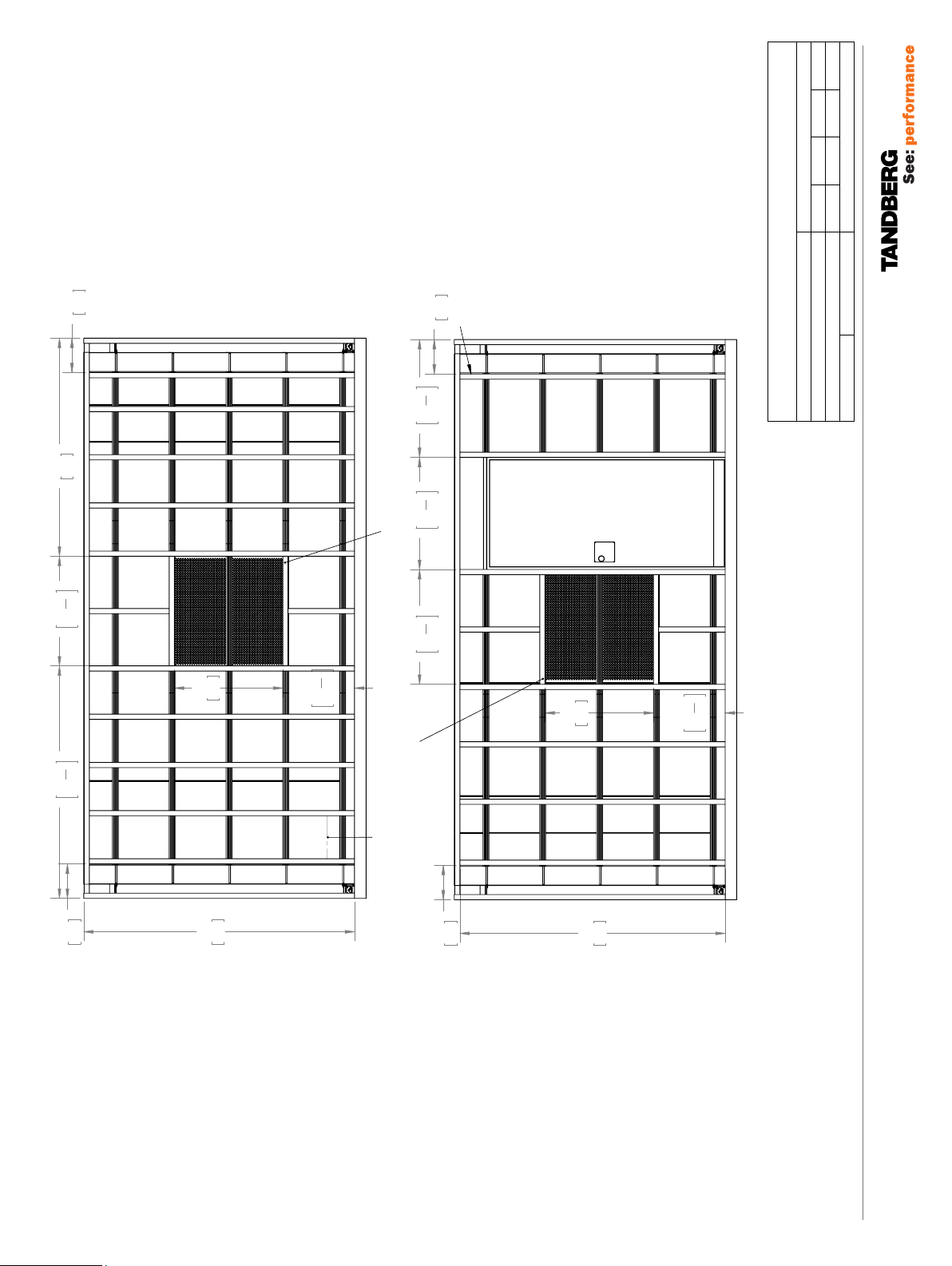
Frame around area for insulation boards
TANDBERG T3
A3
01
04.11.08
Date:
Related Tandberg Product -
Sheet Size:
Revision:
www.tandberg.com
1:25
TANDBERG
Scale:
119086
T3 Short Structure
Drw. No.:
Unit: mm / "
Doc. Title:
Sign.:
1
955
1
2025
300
"
37
"
79
2
2
12"
945
2360
37"
93"
625
"
1
2
1000
39
"
1
24
2
Gap between the
vertical lattices
300 - approx. 600mm
Frame around area for insulation boards
12"
300
945
37"
2311
91"
625
"
1
2
24
TA N D B E RG
Telepresence T3
PA GE 1 8 /22
119076.02 TELEPRESENCE T3 ROOM REQUIREMENTS 12.08

TANDBERG T3
01
A3
04.11.08
Date:
Related Tandberg Product -
Sheet Size:
www.tandberg.com
Revision:
1:25
Frame around area for insulation boards
Centerline
"
1
2
1485
58
"
1
2
120
3056,70
TANDBERG
Scale:
T3 Long Structure
119087
Drw. No.:
Unit: mm / "
Doc. Title:
Sign.:
"
1
2
141
3596,70
TA N D B E RG
Telepresence T3
93"
2360
89"
2260
1
2090
"
82
Area for mounting/changing Led
2
PA GE 1 9 /22
119076.02 TELEPRESENCE T3 ROOM REQUIREMENTS 12.08

TA N D B E RG
Telepresence T3
TANDBERG T3
01
A3
04.11.08
Date:
Related Tandberg Product -
Sheet Size:
Revision:
www.tandberg.com
1:25
4"
98,50
80
3"
"
1
2
1557
61
Base opening
615
1193
24"
47"
75
3"
Center line
3833
2132
3757
151"
84"
148"
TANDBERG
Scale:
T3 Structural Elements
119088
Drw. No.:
Unit: mm / "
Doc. Title:
Sign.:
A
A
Floor power outlet
recommended hole
TA N D B E RG
Telepresence T3
Base opening
Structural element
Base openings
Structual element
PA GE 2 0 /22
119076.02 TELEPRESENCE T3 ROOM REQUIREMENTS 12.08

"
3
4
20
"
3
Power / LAN outlets
Hardwire outlet for
LED lights
LED mounted on bracket
69
2
03
01.12.08
TANDBERG T3
02
17.11.08
01
A3
04.11.08
Date:
Related Tandberg Product -
Sheet Size:
www.tandberg.com
4
Revision:
1:25
Optimal height /
suspended ceiling
3
2550
"
8
100
T3 Lighting
119089
Drw. No.:
Doc. Title:
Sign.:
Scale:
Unit: mm / "
DETAIL D
SCALE 1 : 5
TANDBERG
D
Removable baseboard
for access to outlets.
Mounted with magnets.
TA N D B E RG
Telepresence T3
50
2"
"
3
78
2000
"
1
2
724
28
4
"
3
89
2280
4
Picture center
PA GE 2 1 /22
119076.02 TELEPRESENCE T3 ROOM REQUIREMENTS 12.08

140
03
01.12.08
TANDBERG T3
02
"
3
8
85
3
"
1
2
5
"
1
8
4600
181
cable
from Doc.Cam. to
T3 cable tray
above suspended ceiling
Wiring of VGA
17.11.08
01
A3
04.11.08
www.tandberg.com
TANDBERG
Sheet Size:
Date:
Related Tandberg Product -
Revision:
1:25
Scale:
T3 Cabling
119168
:
Doc. Title:
Sign.:
Unit: mm/"
Drw No.
4 (US 8)
Video Lan
Video LAN
5 (US 8)
Customers Lan
Customer’s LAN
On floor Cable Routing
- Transport cables from T3
Cables runs between LEDs and base board
On Floor Cable Routing
- Transport cables from T3
Power / AV / Lan
Centerline
RS-232 cable
from Doc.Cam. to
T3 cable tray
Wiring of
above suspended ceiling
LED 5LED 4LED 3LED 2LED 1
3 x junction box
Cables runs between LEDs and base board
LED organisation Europe (Junction box and extra cables supplied by local electrician)
LED 5LED 4LED 3LED 2LED 1
LED organisation USA (Jumper cables and leader cable supplied by Tandberg)
4 x jumper Cable
Hardwire outlet for light,
mounted sideways
on wood lattice.
TA N D B E RG
Telepresence T3
Master Panel
Light
(Controls fuse groups A,B and C)
Fire Emergency switch
Control Data
Panel
Leader Cable
Leader Cable
Leader Cable
PA GE 2 2 /22
119076.02 TELEPRESENCE T3 ROOM REQUIREMENTS 12.08
 Loading...