

USER’S GUIDE
433568-01

Copyright © 2006 Tandberg Data ASA.
All trademarks within this document are the property of their respective owners. Every effort has been made to
acknowledge trademarks and their owners. Trademarked names are used solel y for identification or exemplary
purposes: any omissions are unintentional.
This publication may describe designs for which patents are granted or pending. By publishing this information,
Tandberg Data ASA conveys no license under any patent or any other rights. Every effort has been made to avoid errors
in text and diagrams. However, Tandberg Data ASA assumes no responsibility for any errors, which may appear in this
publication.It is the policy of Tandberg Data ASA to improve products as new techniques and components become
available. Tandberg Data ASA therefore reserves the right to change specifications at any time. We would appreciate
any comments on this publication.
Published: July 2006 Part No.: 433568-01
ADIC P/N: 6-01710-01, Rev A
International headquarters
Tandberg Data ASA
Kjelsåsveien 161, Oslo
P.O. Box 134 Kjelsås
N-0411 Oslo, Norway
Tel.: +47 22 18 90 90
Fax: +47 22 18 95 50
www.tandberg.com
Worldwide subsidiaries
Tandberg Data Corp.
12860 Danielson Court
Poway, CA 92064, U.S.A.
Tel.: +1 858 726 1800
Fax: +1 858 726 1801
Tandberg Data GmbH
Feldstrasse 81
D-44141 Dortmund, Germany
Tel.: +49 231 5436 0
Fax: +49 231 5436 111
Tandberg Data S.A.
16-18, avenue Morane Saulnier - Bât.A
78941 Vélizy Cedex, France
Tel.: +33 (0)1 39 26 01 01
Fax: +33 (0)1 34 65 02 89
Tandberg Data (Asia) Pte. Ltd
20 Bendemeer Road, #04-05 Cyberhub
Singapore 339914
Tel.: +65 6396 0786
Fax: +65 6396 0787
Tandberg Data (Japan) Inc.
Eitaibashi Eco-Piazza Bldg. 8th floor 29-13
Shinkawa 1-chome, Chuo-ku Tokyo 104-033, Japan
Tel.: +81 3 5566 2871
Fax: +81 3 5566 2875
Tandberg Data (UK) Limited
Bloxham Mill Business Centre
Barford Road
Bloxham
Banbury
Oxfordshire
OX15 4FF
Tel: +44 (0) 8450706916
TANDBERG DATA BeNeLux
Wethouder Rikkerslaan 24
3852 EB Ermelo
The Netherlands
Tel: +31 (0)6 51028107
Fax: +31 (0)341 561837

Contents
1 About This Guide and Your Product 1
Product Safety Statements . . . . . . . . . . . . . . . . . . . . . . . . . . . . . . . . . . . . . . . . . . . . . . . . . . . . . . . . . . . 1
Product Model Number . . . . . . . . . . . . . . . . . . . . . . . . . . . . . . . . . . . . . . . . . . . . . . . . . . . . . . . . . . . . . . 1
Explanation of Symbols and Notes . . . . . . . . . . . . . . . . . . . . . . . . . . . . . . . . . . . . . . . . . . . . . . . . . . . . . 1
Other Documents You Might Need . . . . . . . . . . . . . . . . . . . . . . . . . . . . . . . . . . . . . . . . . . . . . . . . . . . . . 2
Getting More Information or Help . . . . . . . . . . . . . . . . . . . . . . . . . . . . . . . . . . . . . . . . . . . . . . . . . . . . . . 2
2 Description 3
Modules. . . . . . . . . . . . . . . . . . . . . . . . . . . . . . . . . . . . . . . . . . . . . . . . . . . . . . . . . . . . . . . . . . . . . . . . . . 4
5U Control Module. . . . . . . . . . . . . . . . . . . . . . . . . . . . . . . . . . . . . . . . . . . . . . . . . . . . . . . . . . . . . . . 5
9U Expansion Modules . . . . . . . . . . . . . . . . . . . . . . . . . . . . . . . . . . . . . . . . . . . . . . . . . . . . . . . . . . . 5
Stackability . . . . . . . . . . . . . . . . . . . . . . . . . . . . . . . . . . . . . . . . . . . . . . . . . . . . . . . . . . . . . . . . . . . . 5
Unused Storage Slots . . . . . . . . . . . . . . . . . . . . . . . . . . . . . . . . . . . . . . . . . . . . . . . . . . . . . . . . . . . . 6
Front Panel Components. . . . . . . . . . . . . . . . . . . . . . . . . . . . . . . . . . . . . . . . . . . . . . . . . . . . . . . . . . . . . 6
Access Door . . . . . . . . . . . . . . . . . . . . . . . . . . . . . . . . . . . . . . . . . . . . . . . . . . . . . . . . . . . . . . . . . . . . . . 6
I/E Station . . . . . . . . . . . . . . . . . . . . . . . . . . . . . . . . . . . . . . . . . . . . . . . . . . . . . . . . . . . . . . . . . . . . . 7
Operator Panel . . . . . . . . . . . . . . . . . . . . . . . . . . . . . . . . . . . . . . . . . . . . . . . . . . . . . . . . . . . . . . . . . 7
Front Power Switch . . . . . . . . . . . . . . . . . . . . . . . . . . . . . . . . . . . . . . . . . . . . . . . . . . . . . . . . . . . . . . 7
Back Panel Components. . . . . . . . . . . . . . . . . . . . . . . . . . . . . . . . . . . . . . . . . . . . . . . . . . . . . . . . . . . . . 7
Rear Power Switches . . . . . . . . . . . . . . . . . . . . . . . . . . . . . . . . . . . . . . . . . . . . . . . . . . . . . . . . . . . . 8
Power System . . . . . . . . . . . . . . . . . . . . . . . . . . . . . . . . . . . . . . . . . . . . . . . . . . . . . . . . . . . . . . . . . . 8
Library Control Blade. . . . . . . . . . . . . . . . . . . . . . . . . . . . . . . . . . . . . . . . . . . . . . . . . . . . . . . . . . . . 10
Robotic System and Barcode Scanner . . . . . . . . . . . . . . . . . . . . . . . . . . . . . . . . . . . . . . . . . . . . . . . . . 11
Tape Drive Support . . . . . . . . . . . . . . . . . . . . . . . . . . . . . . . . . . . . . . . . . . . . . . . . . . . . . . . . . . . . . . . . 12
Library Features . . . . . . . . . . . . . . . . . . . . . . . . . . . . . . . . . . . . . . . . . . . . . . . . . . . . . . . . . . . . . . . . . . 12
Licensable Features . . . . . . . . . . . . . . . . . . . . . . . . . . . . . . . . . . . . . . . . . . . . . . . . . . . . . . . . . . . . 12
Capacity-On-Demand (COD) . . . . . . . . . . . . . . . . . . . . . . . . . . . . . . . . . . . . . . . . . . . . . . . . . . . 13
Partitions . . . . . . . . . . . . . . . . . . . . . . . . . . . . . . . . . . . . . . . . . . . . . . . . . . . . . . . . . . . . . . . . . . . . . . . . 14
Logical Unit Numbering (LUN). . . . . . . . . . . . . . . . . . . . . . . . . . . . . . . . . . . . . . . . . . . . . . . . . . . . . 14
User Interface . . . . . . . . . . . . . . . . . . . . . . . . . . . . . . . . . . . . . . . . . . . . . . . . . . . . . . . . . . . . . . . . . 14
Control Path Modification . . . . . . . . . . . . . . . . . . . . . . . . . . . . . . . . . . . . . . . . . . . . . . . . . . . . . . . . 14
Support for WORM . . . . . . . . . . . . . . . . . . . . . . . . . . . . . . . . . . . . . . . . . . . . . . . . . . . . . . . . . . . . . . . . 14
System Requirements. . . . . . . . . . . . . . . . . . . . . . . . . . . . . . . . . . . . . . . . . . . . . . . . . . . . . . . . . . . . . . 15
3 Setting Up the Library 17
Unpacking the Library . . . . . . . . . . . . . . . . . . . . . . . . . . . . . . . . . . . . . . . . . . . . . . . . . . . . . . . . . . . . . . 17
Tandberg StorageLibrary T128 User’s Guide iii

Unpacking and Inspecting . . . . . . . . . . . . . . . . . . . . . . . . . . . . . . . . . . . . . . . . . . . . . . . . . . . . . . . . 17
Finding a Location. . . . . . . . . . . . . . . . . . . . . . . . . . . . . . . . . . . . . . . . . . . . . . . . . . . . . . . . . . . . . . . . . 18
Initial Setup Road Map . . . . . . . . . . . . . . . . . . . . . . . . . . . . . . . . . . . . . . . . . . . . . . . . . . . . . . . . . . . . . 19
Downloading Drivers . . . . . . . . . . . . . . . . . . . . . . . . . . . . . . . . . . . . . . . . . . . . . . . . . . . . . . . . . . . . . . . 20
4 Understanding the User Interface 21
Common User Interface Elements . . . . . . . . . . . . . . . . . . . . . . . . . . . . . . . . . . . . . . . . . . . . . . . . . . . . 21
System Summary and Subsystem Status . . . . . . . . . . . . . . . . . . . . . . . . . . . . . . . . . . . . . . . . . . . . 23
Home Page . . . . . . . . . . . . . . . . . . . . . . . . . . . . . . . . . . . . . . . . . . . . . . . . . . . . . . . . . . . . . . . . . . . 23
Capacity View . . . . . . . . . . . . . . . . . . . . . . . . . . . . . . . . . . . . . . . . . . . . . . . . . . . . . . . . . . . . . . . 23
Library View . . . . . . . . . . . . . . . . . . . . . . . . . . . . . . . . . . . . . . . . . . . . . . . . . . . . . . . . . . . . . . . . 23
Operator Panel . . . . . . . . . . . . . . . . . . . . . . . . . . . . . . . . . . . . . . . . . . . . . . . . . . . . . . . . . . . . . . . . . . . 24
Operator Panel Keyboards . . . . . . . . . . . . . . . . . . . . . . . . . . . . . . . . . . . . . . . . . . . . . . . . . . . . . . . 24
Web Client . . . . . . . . . . . . . . . . . . . . . . . . . . . . . . . . . . . . . . . . . . . . . . . . . . . . . . . . . . . . . . . . . . . . . . 24
Menu Trees . . . . . . . . . . . . . . . . . . . . . . . . . . . . . . . . . . . . . . . . . . . . . . . . . . . . . . . . . . . . . . . . . . . . . . 24
User Privileges . . . . . . . . . . . . . . . . . . . . . . . . . . . . . . . . . . . . . . . . . . . . . . . . . . . . . . . . . . . . . . . . . . . 26
User Access . . . . . . . . . . . . . . . . . . . . . . . . . . . . . . . . . . . . . . . . . . . . . . . . . . . . . . . . . . . . . . . . . . . . . 27
5 Configuring Your Library 29
About the Setup Wizard. . . . . . . . . . . . . . . . . . . . . . . . . . . . . . . . . . . . . . . . . . . . . . . . . . . . . . . . . . . . . 29
Using the Default Administrative User Account. . . . . . . . . . . . . . . . . . . . . . . . . . . . . . . . . . . . . . . . 29
Completing the Library Configuration With Menu Commands . . . . . . . . . . . . . . . . . . . . . . . . . . . . 30
Using the Setup Wizard. . . . . . . . . . . . . . . . . . . . . . . . . . . . . . . . . . . . . . . . . . . . . . . . . . . . . . . . . . . . . 30
Setup Wizard Tasks . . . . . . . . . . . . . . . . . . . . . . . . . . . . . . . . . . . . . . . . . . . . . . . . . . . . . . . . . . . . 31
Choosing the Interface: Local or Remote . . . . . . . . . . . . . . . . . . . . . . . . . . . . . . . . . . . . . . . . . . . . . . . 32
Remote Configuration . . . . . . . . . . . . . . . . . . . . . . . . . . . . . . . . . . . . . . . . . . . . . . . . . . . . . . . . . . . 32
Configuring Network Settings . . . . . . . . . . . . . . . . . . . . . . . . . . . . . . . . . . . . . . . . . . . . . . . . . . . . . . . . 33
Working With Partitions . . . . . . . . . . . . . . . . . . . . . . . . . . . . . . . . . . . . . . . . . . . . . . . . . . . . . . . . . . . . . 34
Automatically Creating Partitions. . . . . . . . . . . . . . . . . . . . . . . . . . . . . . . . . . . . . . . . . . . . . . . . . . . 35
Manually Creating Partitions . . . . . . . . . . . . . . . . . . . . . . . . . . . . . . . . . . . . . . . . . . . . . . . . . . . . . . 35
Modifying Partitions . . . . . . . . . . . . . . . . . . . . . . . . . . . . . . . . . . . . . . . . . . . . . . . . . . . . . . . . . . . . . 36
Deleting Partitions . . . . . . . . . . . . . . . . . . . . . . . . . . . . . . . . . . . . . . . . . . . . . . . . . . . . . . . . . . . . . . 37
Deleting Partitions Before Permanently Removing Expansion Modules. . . . . . . . . . . . . . . . . . . 37
Changing Partition Access . . . . . . . . . . . . . . . . . . . . . . . . . . . . . . . . . . . . . . . . . . . . . . . . . . . . . . . 38
Changing Partition Modes . . . . . . . . . . . . . . . . . . . . . . . . . . . . . . . . . . . . . . . . . . . . . . . . . . . . . . . . 38
Configuring Cleaning Slots . . . . . . . . . . . . . . . . . . . . . . . . . . . . . . . . . . . . . . . . . . . . . . . . . . . . . . . . . . 39
Configuring I/E Station Slots . . . . . . . . . . . . . . . . . . . . . . . . . . . . . . . . . . . . . . . . . . . . . . . . . . . . . . . . . 40
Configuring Zero I/E Station Slots . . . . . . . . . . . . . . . . . . . . . . . . . . . . . . . . . . . . . . . . . . . . . . . . . . 41
Setting Tape Drive Parameters . . . . . . . . . . . . . . . . . . . . . . . . . . . . . . . . . . . . . . . . . . . . . . . . . . . . . . . 42
Modifying the Control Path . . . . . . . . . . . . . . . . . . . . . . . . . . . . . . . . . . . . . . . . . . . . . . . . . . . . . . . . . . 43
Applying License Keys . . . . . . . . . . . . . . . . . . . . . . . . . . . . . . . . . . . . . . . . . . . . . . . . . . . . . . . . . . . . . 43
Obtaining a Capacity-On-Demand License Key . . . . . . . . . . . . . . . . . . . . . . . . . . . . . . . . . . . . . . . . . . 44
Setting Customer Contact Information . . . . . . . . . . . . . . . . . . . . . . . . . . . . . . . . . . . . . . . . . . . . . . . . . 46
Configuring the Library E-mail Account. . . . . . . . . . . . . . . . . . . . . . . . . . . . . . . . . . . . . . . . . . . . . . . . . 46
Working With E-mail Notifications . . . . . . . . . . . . . . . . . . . . . . . . . . . . . . . . . . . . . . . . . . . . . . . . . . . . . 47
Creating E-mail Notifications . . . . . . . . . . . . . . . . . . . . . . . . . . . . . . . . . . . . . . . . . . . . . . . . . . . . . . 47
Modifying E-mail Notifications . . . . . . . . . . . . . . . . . . . . . . . . . . . . . . . . . . . . . . . . . . . . . . . . . . . . . 48
Deleting E-mail Notifications . . . . . . . . . . . . . . . . . . . . . . . . . . . . . . . . . . . . . . . . . . . . . . . . . . . . . . 48
Working With User Accounts. . . . . . . . . . . . . . . . . . . . . . . . . . . . . . . . . . . . . . . . . . . . . . . . . . . . . . . . . 48
Creating User Accounts. . . . . . . . . . . . . . . . . . . . . . . . . . . . . . . . . . . . . . . . . . . . . . . . . . . . . . . . . . 48
Modifying User Accounts. . . . . . . . . . . . . . . . . . . . . . . . . . . . . . . . . . . . . . . . . . . . . . . . . . . . . . . . . 49
iv Contents

Deleting User Accounts. . . . . . . . . . . . . . . . . . . . . . . . . . . . . . . . . . . . . . . . . . . . . . . . . . . . . . . . . . 49
Setting the Date and Time. . . . . . . . . . . . . . . . . . . . . . . . . . . . . . . . . . . . . . . . . . . . . . . . . . . . . . . . . . . 50
Managing the Network. . . . . . . . . . . . . . . . . . . . . . . . . . . . . . . . . . . . . . . . . . . . . . . . . . . . . . . . . . . . . . 50
Enabling SSL. . . . . . . . . . . . . . . . . . . . . . . . . . . . . . . . . . . . . . . . . . . . . . . . . . . . . . . . . . . . . . . . . . 51
Setting Trap Registration. . . . . . . . . . . . . . . . . . . . . . . . . . . . . . . . . . . . . . . . . . . . . . . . . . . . . . . . . 51
Enabling SNMP Version . . . . . . . . . . . . . . . . . . . . . . . . . . . . . . . . . . . . . . . . . . . . . . . . . . . . . . . . . 52
Configuring Library Security Settings . . . . . . . . . . . . . . . . . . . . . . . . . . . . . . . . . . . . . . . . . . . . . . . . . . 52
Configuring the Internal Network. . . . . . . . . . . . . . . . . . . . . . . . . . . . . . . . . . . . . . . . . . . . . . . . . . . . . . 53
Configuring System Settings . . . . . . . . . . . . . . . . . . . . . . . . . . . . . . . . . . . . . . . . . . . . . . . . . . . . . . . . . 53
Configuring Operator Panel Display Settings . . . . . . . . . . . . . . . . . . . . . . . . . . . . . . . . . . . . . . . . . . . . 54
Registering the Library . . . . . . . . . . . . . . . . . . . . . . . . . . . . . . . . . . . . . . . . . . . . . . . . . . . . . . . . . . . . . 54
6 Running Your Library 55
Logging In . . . . . . . . . . . . . . . . . . . . . . . . . . . . . . . . . . . . . . . . . . . . . . . . . . . . . . . . . . . . . . . . . . . . . . . 55
Logging Out. . . . . . . . . . . . . . . . . . . . . . . . . . . . . . . . . . . . . . . . . . . . . . . . . . . . . . . . . . . . . . . . . . . . . . 55
Understanding the Location Coordinates . . . . . . . . . . . . . . . . . . . . . . . . . . . . . . . . . . . . . . . . . . . . . . . 56
Modules. . . . . . . . . . . . . . . . . . . . . . . . . . . . . . . . . . . . . . . . . . . . . . . . . . . . . . . . . . . . . . . . . . . . . . . . . 56
Columns . . . . . . . . . . . . . . . . . . . . . . . . . . . . . . . . . . . . . . . . . . . . . . . . . . . . . . . . . . . . . . . . . . . . . 57
Slots. . . . . . . . . . . . . . . . . . . . . . . . . . . . . . . . . . . . . . . . . . . . . . . . . . . . . . . . . . . . . . . . . . . . . . . . . 57
Tape Drives . . . . . . . . . . . . . . . . . . . . . . . . . . . . . . . . . . . . . . . . . . . . . . . . . . . . . . . . . . . . . . . . . . . 57
Power Supplies . . . . . . . . . . . . . . . . . . . . . . . . . . . . . . . . . . . . . . . . . . . . . . . . . . . . . . . . . . . . . . . . 57
Performing Media Operations . . . . . . . . . . . . . . . . . . . . . . . . . . . . . . . . . . . . . . . . . . . . . . . . . . . . . . . . 57
Importing Media. . . . . . . . . . . . . . . . . . . . . . . . . . . . . . . . . . . . . . . . . . . . . . . . . . . . . . . . . . . . . . . . 58
Bulkloading . . . . . . . . . . . . . . . . . . . . . . . . . . . . . . . . . . . . . . . . . . . . . . . . . . . . . . . . . . . . . . . . . . . 59
Moving Media . . . . . . . . . . . . . . . . . . . . . . . . . . . . . . . . . . . . . . . . . . . . . . . . . . . . . . . . . . . . . . . . . 60
Exporting Media. . . . . . . . . . . . . . . . . . . . . . . . . . . . . . . . . . . . . . . . . . . . . . . . . . . . . . . . . . . . . . . . 60
Loading Tape Drives . . . . . . . . . . . . . . . . . . . . . . . . . . . . . . . . . . . . . . . . . . . . . . . . . . . . . . . . . . . . 61
Unloading Tape Drives . . . . . . . . . . . . . . . . . . . . . . . . . . . . . . . . . . . . . . . . . . . . . . . . . . . . . . . . . . 62
Changing the Tape Drive Mode. . . . . . . . . . . . . . . . . . . . . . . . . . . . . . . . . . . . . . . . . . . . . . . . . . . . 63
About Cleaning Tape Drives . . . . . . . . . . . . . . . . . . . . . . . . . . . . . . . . . . . . . . . . . . . . . . . . . . . . . . 63
Enabling AutoClean. . . . . . . . . . . . . . . . . . . . . . . . . . . . . . . . . . . . . . . . . . . . . . . . . . . . . . . . . . . . . 64
Importing Cleaning Media . . . . . . . . . . . . . . . . . . . . . . . . . . . . . . . . . . . . . . . . . . . . . . . . . . . . . . . . 64
Exporting Cleaning Media . . . . . . . . . . . . . . . . . . . . . . . . . . . . . . . . . . . . . . . . . . . . . . . . . . . . . . . . 65
Manually Cleaning Tape Drives. . . . . . . . . . . . . . . . . . . . . . . . . . . . . . . . . . . . . . . . . . . . . . . . . . . . 66
Locking and Unlocking the I/E Stations. . . . . . . . . . . . . . . . . . . . . . . . . . . . . . . . . . . . . . . . . . . . . . . . . 66
Shutting Down or Restarting the Library . . . . . . . . . . . . . . . . . . . . . . . . . . . . . . . . . . . . . . . . . . . . . . . . 67
7 Getting Information 69
Viewing System Information . . . . . . . . . . . . . . . . . . . . . . . . . . . . . . . . . . . . . . . . . . . . . . . . . . . . . . . . . 69
Viewing the Library Configuration . . . . . . . . . . . . . . . . . . . . . . . . . . . . . . . . . . . . . . . . . . . . . . . . . . . . . 69
Viewing Network Settings . . . . . . . . . . . . . . . . . . . . . . . . . . . . . . . . . . . . . . . . . . . . . . . . . . . . . . . . . . . 70
Viewing Logged in Users. . . . . . . . . . . . . . . . . . . . . . . . . . . . . . . . . . . . . . . . . . . . . . . . . . . . . . . . . . . . 70
Viewing Slot Information . . . . . . . . . . . . . . . . . . . . . . . . . . . . . . . . . . . . . . . . . . . . . . . . . . . . . . . . . . . . 70
Viewing Information About the Tandberg StorageLibrary T128 . . . . . . . . . . . . . . . . . . . . . . . . . . . . . . 71
8 Updating Library and Tape Drive Firmware 73
Updating Library Firmware . . . . . . . . . . . . . . . . . . . . . . . . . . . . . . . . . . . . . . . . . . . . . . . . . . . . . . . . . . 73
About Tape Drive Operations . . . . . . . . . . . . . . . . . . . . . . . . . . . . . . . . . . . . . . . . . . . . . . . . . . . . . . . . 75
Tandberg StorageLibrary T128 User’s Guide v

Creating a FUP Tape. . . . . . . . . . . . . . . . . . . . . . . . . . . . . . . . . . . . . . . . . . . . . . . . . . . . . . . . . . . . 75
Erasing a FUP Tape . . . . . . . . . . . . . . . . . . . . . . . . . . . . . . . . . . . . . . . . . . . . . . . . . . . . . . . . . . . . 77
Using a FUP Tape to Update Tape Drive Firmware . . . . . . . . . . . . . . . . . . . . . . . . . . . . . . . . . . . . 78
Using an Image File to Update Tape Drive Firmware . . . . . . . . . . . . . . . . . . . . . . . . . . . . . . . . . . . 80
Order a New FUP Tape From Technical Support. . . . . . . . . . . . . . . . . . . . . . . . . . . . . . . . . . . . . . . . . 81
Retrieving Tape Drive Logs. . . . . . . . . . . . . . . . . . . . . . . . . . . . . . . . . . . . . . . . . . . . . . . . . . . . . . . . . . 81
9 Installing, Removing, and Replacing 83
Taking the Library Online/Offline. . . . . . . . . . . . . . . . . . . . . . . . . . . . . . . . . . . . . . . . . . . . . . . . . . . . . . 84
Taking a Library Online . . . . . . . . . . . . . . . . . . . . . . . . . . . . . . . . . . . . . . . . . . . . . . . . . . . . . . . . . . 84
Taking a Library Offline . . . . . . . . . . . . . . . . . . . . . . . . . . . . . . . . . . . . . . . . . . . . . . . . . . . . . . . . . . 84
Cabling the Library . . . . . . . . . . . . . . . . . . . . . . . . . . . . . . . . . . . . . . . . . . . . . . . . . . . . . . . . . . . . . . . . 84
Connecting Library Cables (SCSI) . . . . . . . . . . . . . . . . . . . . . . . . . . . . . . . . . . . . . . . . . . . . . . . . . 84
Connecting Library Cables (Fibre Channel) . . . . . . . . . . . . . . . . . . . . . . . . . . . . . . . . . . . . . . . . . . 87
Installing a Stand-Alone 5U Control Module . . . . . . . . . . . . . . . . . . . . . . . . . . . . . . . . . . . . . . . . . . . . . 89
Installing a New 14U Library Configuration . . . . . . . . . . . . . . . . . . . . . . . . . . . . . . . . . . . . . . . . . . . . . . 90
Preparing to Install a 14U Library . . . . . . . . . . . . . . . . . . . . . . . . . . . . . . . . . . . . . . . . . . . . . . . . . . 90
Installing the 9U Expansion Module . . . . . . . . . . . . . . . . . . . . . . . . . . . . . . . . . . . . . . . . . . . . . . . . 92
Installing the 5U Control Module . . . . . . . . . . . . . . . . . . . . . . . . . . . . . . . . . . . . . . . . . . . . . . . . . . . 95
Preparing to Use the 14U Library . . . . . . . . . . . . . . . . . . . . . . . . . . . . . . . . . . . . . . . . . . . . . . . . . . 96
Adding a 9U Expansion Module to an Existing Library . . . . . . . . . . . . . . . . . . . . . . . . . . . . . . . . . . . . . 97
Preparing to Install the 9U Expansion Module . . . . . . . . . . . . . . . . . . . . . . . . . . . . . . . . . . . . . . . . 98
Unstacking the Existing Modules. . . . . . . . . . . . . . . . . . . . . . . . . . . . . . . . . . . . . . . . . . . . . . . . . . . 99
Installing the New 9U Expansion Module . . . . . . . . . . . . . . . . . . . . . . . . . . . . . . . . . . . . . . . . . . . 102
Preparing to Use the Library . . . . . . . . . . . . . . . . . . . . . . . . . . . . . . . . . . . . . . . . . . . . . . . . . . . . . 105
Removing 9U Expansion Modules From an Existing Library . . . . . . . . . . . . . . . . . . . . . . . . . . . . . . . 107
Preparing to Permanently Remove the 9U Expansion Module. . . . . . . . . . . . . . . . . . . . . . . . . . . 107
Removing the 9U Expansion Module . . . . . . . . . . . . . . . . . . . . . . . . . . . . . . . . . . . . . . . . . . . . . . 109
Preparing to Use the New Library Configuration. . . . . . . . . . . . . . . . . . . . . . . . . . . . . . . . . . . . . . 112
Replacing the 5U Library Control Module . . . . . . . . . . . . . . . . . . . . . . . . . . . . . . . . . . . . . . . . . . . . . . 115
Preparing to Remove the 5U Control Module . . . . . . . . . . . . . . . . . . . . . . . . . . . . . . . . . . . . . . . . 115
Removing the 5U Control Module . . . . . . . . . . . . . . . . . . . . . . . . . . . . . . . . . . . . . . . . . . . . . . . . . 117
Replacing the 5U Control Module . . . . . . . . . . . . . . . . . . . . . . . . . . . . . . . . . . . . . . . . . . . . . . . . . 120
Preparing to Use the 5U Control Module. . . . . . . . . . . . . . . . . . . . . . . . . . . . . . . . . . . . . . . . . . . . 122
Replacing a 9U Expansion Module . . . . . . . . . . . . . . . . . . . . . . . . . . . . . . . . . . . . . . . . . . . . . . . . . . . 123
Preparing to Remove the 9U Expansion Module . . . . . . . . . . . . . . . . . . . . . . . . . . . . . . . . . . . . . 123
Removing the 9U Expansion Module . . . . . . . . . . . . . . . . . . . . . . . . . . . . . . . . . . . . . . . . . . . . . . 125
Replacing the 9U Expansion Module . . . . . . . . . . . . . . . . . . . . . . . . . . . . . . . . . . . . . . . . . . . . . . 129
Preparing to Use the 9U Expansion Module . . . . . . . . . . . . . . . . . . . . . . . . . . . . . . . . . . . . . . . . . 132
Removing and Replacing the Library Control Blade and LCB Compact Flash Card. . . . . . . . . . . . . . 133
Replacing the LCB and LCB Compact Flash Card . . . . . . . . . . . . . . . . . . . . . . . . . . . . . . . . . . . . 133
Replacing the LCB. . . . . . . . . . . . . . . . . . . . . . . . . . . . . . . . . . . . . . . . . . . . . . . . . . . . . . . . . . . . . 135
Adding, Removing, and Replacing Power Supplies . . . . . . . . . . . . . . . . . . . . . . . . . . . . . . . . . . . . . . 136
Adding a Redundant Power Supply. . . . . . . . . . . . . . . . . . . . . . . . . . . . . . . . . . . . . . . . . . . . . . . . 136
Permanently Removing a Redundant Power Supply . . . . . . . . . . . . . . . . . . . . . . . . . . . . . . . . . . 137
Removing and Replacing a Power Supply . . . . . . . . . . . . . . . . . . . . . . . . . . . . . . . . . . . . . . . . . . 137
Installing the Rackmount Kit . . . . . . . . . . . . . . . . . . . . . . . . . . . . . . . . . . . . . . . . . . . . . . . . . . . . . . . . 138
Preparing Rackmount Kit for Installation . . . . . . . . . . . . . . . . . . . . . . . . . . . . . . . . . . . . . . . . . . . . 138
Installing the Rackmount Shelves . . . . . . . . . . . . . . . . . . . . . . . . . . . . . . . . . . . . . . . . . . . . . . . . . 139
Preparing Your Library for Rack Installation . . . . . . . . . . . . . . . . . . . . . . . . . . . . . . . . . . . . . . . . . 141
Installing Modules in the Rack. . . . . . . . . . . . . . . . . . . . . . . . . . . . . . . . . . . . . . . . . . . . . . . . . . . . 141
Installing Additional Modules Into the Rack. . . . . . . . . . . . . . . . . . . . . . . . . . . . . . . . . . . . . . . . . . 143
Adding, Removing, and Replacing Tape Drives . . . . . . . . . . . . . . . . . . . . . . . . . . . . . . . . . . . . . . . . . 148
Adding a Tape Drive . . . . . . . . . . . . . . . . . . . . . . . . . . . . . . . . . . . . . . . . . . . . . . . . . . . . . . . . . . . 149
vi Contents

Permanently Removing a Tape Drive . . . . . . . . . . . . . . . . . . . . . . . . . . . . . . . . . . . . . . . . . . . . . . 149
Removing and Replacing a Tape Drive. . . . . . . . . . . . . . . . . . . . . . . . . . . . . . . . . . . . . . . . . . . . . 150
10 Troubleshooting 153
About RAS Tickets . . . . . . . . . . . . . . . . . . . . . . . . . . . . . . . . . . . . . . . . . . . . . . . . . . . . . . . . . . . . . . . 153
Viewing RAS Tickets . . . . . . . . . . . . . . . . . . . . . . . . . . . . . . . . . . . . . . . . . . . . . . . . . . . . . . . . . . . 154
Resolving RAS Tickets . . . . . . . . . . . . . . . . . . . . . . . . . . . . . . . . . . . . . . . . . . . . . . . . . . . . . . . . . 154
Capturing Snapshots of Library Information . . . . . . . . . . . . . . . . . . . . . . . . . . . . . . . . . . . . . . . . . . . . 155
About Saving and Restoring the Configuration . . . . . . . . . . . . . . . . . . . . . . . . . . . . . . . . . . . . . . . . . . 155
Saving the Configuration . . . . . . . . . . . . . . . . . . . . . . . . . . . . . . . . . . . . . . . . . . . . . . . . . . . . . . . . 155
Restoring the Configuration and Library Firmware . . . . . . . . . . . . . . . . . . . . . . . . . . . . . . . . . . . . 156
Identifying Tape Drives . . . . . . . . . . . . . . . . . . . . . . . . . . . . . . . . . . . . . . . . . . . . . . . . . . . . . . . . . . . . 156
Configuring the Internal Network. . . . . . . . . . . . . . . . . . . . . . . . . . . . . . . . . . . . . . . . . . . . . . . . . . . . . 157
Interpreting LEDs. . . . . . . . . . . . . . . . . . . . . . . . . . . . . . . . . . . . . . . . . . . . . . . . . . . . . . . . . . . . . . . . . 158
LCB LEDs . . . . . . . . . . . . . . . . . . . . . . . . . . . . . . . . . . . . . . . . . . . . . . . . . . . . . . . . . . . . . . . . . . . 158
Amber LED on the LCB. . . . . . . . . . . . . . . . . . . . . . . . . . . . . . . . . . . . . . . . . . . . . . . . . . . . . . . 158
Servicing the LCB Based on LED Status . . . . . . . . . . . . . . . . . . . . . . . . . . . . . . . . . . . . . . . . . 159
Tape Drive LEDs . . . . . . . . . . . . . . . . . . . . . . . . . . . . . . . . . . . . . . . . . . . . . . . . . . . . . . . . . . . . . . 159
Fibre Port Link LED on Tape Drives . . . . . . . . . . . . . . . . . . . . . . . . . . . . . . . . . . . . . . . . . . . . . . . 160
Power Supply LEDs. . . . . . . . . . . . . . . . . . . . . . . . . . . . . . . . . . . . . . . . . . . . . . . . . . . . . . . . . . . . 161
11 Working With Cartridges and Barcodes 163
Handling Cartridges Properly . . . . . . . . . . . . . . . . . . . . . . . . . . . . . . . . . . . . . . . . . . . . . . . . . . . . . . . 163
Write-Protecting Cartridges. . . . . . . . . . . . . . . . . . . . . . . . . . . . . . . . . . . . . . . . . . . . . . . . . . . . . . . . . 164
Barcode Requirements . . . . . . . . . . . . . . . . . . . . . . . . . . . . . . . . . . . . . . . . . . . . . . . . . . . . . . . . . . . . 164
Installing Barcode Labels . . . . . . . . . . . . . . . . . . . . . . . . . . . . . . . . . . . . . . . . . . . . . . . . . . . . . . . . . . 165
12 Specifications 167
Library Specifications Summary . . . . . . . . . . . . . . . . . . . . . . . . . . . . . . . . . . . . . . . . . . . . . . . . . . . . . 167
Library Capacity. . . . . . . . . . . . . . . . . . . . . . . . . . . . . . . . . . . . . . . . . . . . . . . . . . . . . . . . . . . . . . . . . . 168
Library Environmental Specifications . . . . . . . . . . . . . . . . . . . . . . . . . . . . . . . . . . . . . . . . . . . . . . . . . 168
Library Dimensions . . . . . . . . . . . . . . . . . . . . . . . . . . . . . . . . . . . . . . . . . . . . . . . . . . . . . . . . . . . . . . . 169
Library Component Weights . . . . . . . . . . . . . . . . . . . . . . . . . . . . . . . . . . . . . . . . . . . . . . . . . . . . . . . . 169
Electrical Specifications. . . . . . . . . . . . . . . . . . . . . . . . . . . . . . . . . . . . . . . . . . . . . . . . . . . . . . . . . . . . 170
Library Power Consumption and Heat Output. . . . . . . . . . . . . . . . . . . . . . . . . . . . . . . . . . . . . . . . 170
13 Glossary 173
Tandberg StorageLibrary T128 User’s Guide vii

viii Contents

Tables
Table 1 Available Library Configurations . . . . . . . . . . . . . . . . . . . . . . . . . . . . . . . . . . . . . . . . . . . . . . . 4
Table 2 Licensed Slots Per Library Configuration . . . . . . . . . . . . . . . . . . . . . . . . . . . . . . . . . . . . . . . 14
Table 3 Web Client Menus . . . . . . . . . . . . . . . . . . . . . . . . . . . . . . . . . . . . . . . . . . . . . . . . . . . . . . . . 25
Table 4 Operator Panel Menus . . . . . . . . . . . . . . . . . . . . . . . . . . . . . . . . . . . . . . . . . . . . . . . . . . . . . 25
Table 5 Number of Partitions Supported . . . . . . . . . . . . . . . . . . . . . . . . . . . . . . . . . . . . . . . . . . . . . . 34
Table 6 Number of I/E Station Slots Available Per Base System . . . . . . . . . . . . . . . . . . . . . . . . . . . 41
Table 7 Activated Slots Per Available Configuration . . . . . . . . . . . . . . . . . . . . . . . . . . . . . . . . . . . . . 44
Table 8 Cover Plate Location . . . . . . . . . . . . . . . . . . . . . . . . . . . . . . . . . . . . . . . . . . . . . . . . . . . . . . 92
Table 9 Cover Plate Location after Removing a 9U Expansion Module . . . . . . . . . . . . . . . . . . . . . 112
Table 10 Library Control Blade LEDs . . . . . . . . . . . . . . . . . . . . . . . . . . . . . . . . . . . . . . . . . . . . . . . . 158
Table 11 Amber LED on the Library Control Blade . . . . . . . . . . . . . . . . . . . . . . . . . . . . . . . . . . . . . . 159
Table 12 Tape Drive Activity . . . . . . . . . . . . . . . . . . . . . . . . . . . . . . . . . . . . . . . . . . . . . . . . . . . . . . . 160
Table 13 Fibre Port Link LED on Tape Drive . . . . . . . . . . . . . . . . . . . . . . . . . . . . . . . . . . . . . . . . . . . 160
Table 14 Power Supply LEDs . . . . . . . . . . . . . . . . . . . . . . . . . . . . . . . . . . . . . . . . . . . . . . . . . . . . . . 161
Table 15 Library Specification Summary . . . . . . . . . . . . . . . . . . . . . . . . . . . . . . . . . . . . . . . . . . . . . . 167
Table 16 Library Capacity . . . . . . . . . . . . . . . . . . . . . . . . . . . . . . . . . . . . . . . . . . . . . . . . . . . . . . . . . 168
Table 17 Library Environmental Specification . . . . . . . . . . . . . . . . . . . . . . . . . . . . . . . . . . . . . . . . . . 168
Table 18 Library Dimensions . . . . . . . . . . . . . . . . . . . . . . . . . . . . . . . . . . . . . . . . . . . . . . . . . . . . . . . 169
Table 19 Library Component Weight . . . . . . . . . . . . . . . . . . . . . . . . . . . . . . . . . . . . . . . . . . . . . . . . . 169
Table 20 Library Typical Power Consumption and Heat Output . . . . . . . . . . . . . . . . . . . . . . . . . . . . 170
Tandberg StorageLibrary T128 User’s Guide ix

x Tables

Figures
Figure 1 5U Library Configuration (Stand-Alone 5U Control Module) . . . . . . . . . . . . . . . . . . . . . . . 3
Figure 2 14U Library Configuration (5U Control Module Plus One 9U Expansion Module) . . . . . . . 4
Figure 3 5U and 14U Library Configurations . . . . . . . . . . . . . . . . . . . . . . . . . . . . . . . . . . . . . . . . . . . 5
Figure 4 Front Panel Components . . . . . . . . . . . . . . . . . . . . . . . . . . . . . . . . . . . . . . . . . . . . . . . . . . . 6
Figure 5 Tandberg StorageLibrary T128 Back Panel Components . . . . . . . . . . . . . . . . . . . . . . . . . . 8
Figure 6 Power System LEDs . . . . . . . . . . . . . . . . . . . . . . . . . . . . . . . . . . . . . . . . . . . . . . . . . . . . . 10
Figure 7 Library Control Blade LEDs . . . . . . . . . . . . . . . . . . . . . . . . . . . . . . . . . . . . . . . . . . . . . . . . 11
Figure 8 Operator Panel User Interface . . . . . . . . . . . . . . . . . . . . . . . . . . . . . . . . . . . . . . . . . . . . . . 22
Figure 9 Web Client User Interface . . . . . . . . . . . . . . . . . . . . . . . . . . . . . . . . . . . . . . . . . . . . . . . . . 22
Figure 10 Library Location Coordinates . . . . . . . . . . . . . . . . . . . . . . . . . . . . . . . . . . . . . . . . . . . . . . 56
Figure 11 Stand-Alone 5U Control Module SCSI Cabling . . . . . . . . . . . . . . . . . . . . . . . . . . . . . . . . 85
Figure 12 Multi-Module SCSI Cabling . . . . . . . . . . . . . . . . . . . . . . . . . . . . . . . . . . . . . . . . . . . . . . . 85
Figure 13 Stand-Alone 5U Control Module Fibre Channel Cabling . . . . . . . . . . . . . . . . . . . . . . . . . 87
Figure 14 Multi-Module Fibre Channel Cabling . . . . . . . . . . . . . . . . . . . . . . . . . . . . . . . . . . . . . . . . 87
Figure 15 Location of Tape Drive LEDs . . . . . . . . . . . . . . . . . . . . . . . . . . . . . . . . . . . . . . . . . . . . . 159
Figure 16 Power Consumption . . . . . . . . . . . . . . . . . . . . . . . . . . . . . . . . . . . . . . . . . . . . . . . . . . . 171
Figure 17 Current Draw . . . . . . . . . . . . . . . . . . . . . . . . . . . . . . . . . . . . . . . . . . . . . . . . . . . . . . . . . 171
Tandberg StorageLibrary T128 User’s Guide xi

xii Figures
About This Guide and Your Product
This guide contains information and instructions necessary for the normal operation and management of
the Tandberg StorageLibrary™ T128 library. This guide is intended for an yone interested in learning about
or anyone that needs to know how to install, configure, and operate the Tandberg StorageLibrary T128
library. Be aware that administrator level privileges are required to configure many of the features described
in this guide.
Product Safety Statements
Note
This product is designed for data storage and retrieval using magnetic tapes. Any other application is not
considered the intended use. Tandberg Data will not be held liable for damage arising from unauthorized
use of the product. The user assumes all risk in this aspect.
This unit is engineered and manufactured to meet all safety and regulatory requirements. Be aware that
improper use may result in bodily injury, damage to the equipment, or interference with other equipment.
Be sure to read all operating instructions in this manual and in the System, Safety, and
Regulatory Information Guide before operating this product.
Product Model Number
The StorageLibrary model number is as follows: i500.
Explanation of Symbols and Notes
The following symbols appear throughout this document to highlight important information.
WARNING
INDICATES A POTENTIALLY HAZARDOUS SITUATION WHICH, IF NOT
AVOIDED, COULD RESULT IN DEATH OR BODILY INJURY.
CAUTION
Tandberg StorageLibrary T128 User’s Guide 1
Indicates a situation that may cause pos sible damage t o eq uip ment , loss
of data, or interference with other equipment.

Note
Indicates important information that helps you make better use of your system.
Other Documents You Might Need
The following documents are also available for this product.These documents can be found in the product
box or at www.tandberg.com.
• Tandberg StorageLibrary 128 Quick Start Guide (433567-xx)
• System, Safety, and Regulatory Information Guide (433605-xx)
Getting More Information or Help
Please visit www.tandberg.com for information about how to contact Tandberg Data.
2 About This Guide and Your Product
Description
The Tandberg StorageLibrary T128 tape library automates the r etrieval, storage, and manag ement of tape
cartridges. Tape cartridges are stored in the library and mounted and dismounted from tape drives using
firmware running on the library or software running on the host systems.
The Tandberg StorageLibrary T128 tape library is different from other tape libraries because it is an
intelligent library. The Tandberg StorageLibrary T128 tape library offers advanced management features
and reliability as well as scalable performance and storage capacity.
The Tandberg StorageLibrary T128 library is designed for ease of installation, configuration, and field
upgrades. The Tandberg StorageLibrary T128 library is built upon two basic building blocks: the 5U control
module and 9U expansion module (where 1U = 1.75").
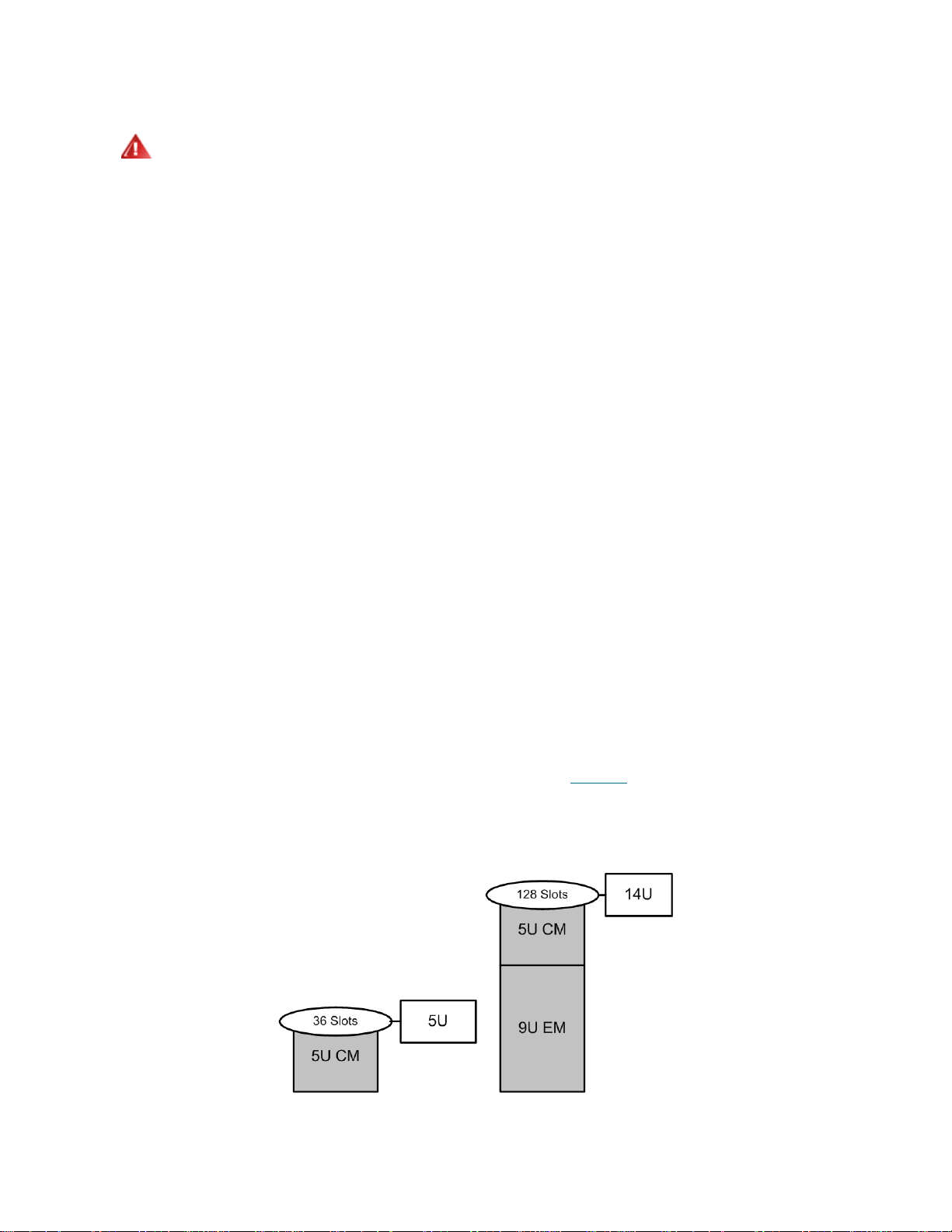
These building blocks form the basis of the following available library configurations:
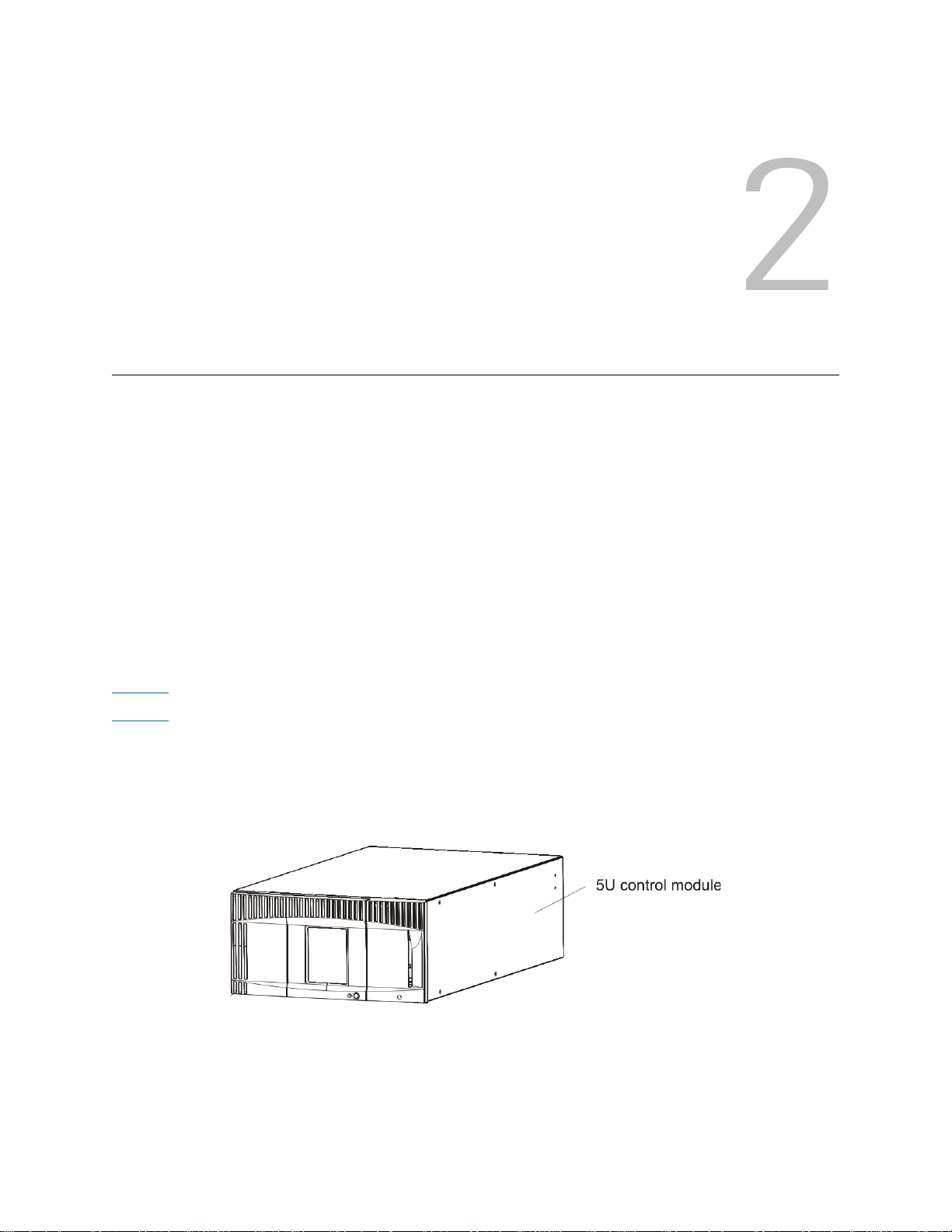
• A 5U library, consisting of a stand-alone control module
• A 14U library, consisting of one 5U control module and one 9U expansion module
Figure 1
Figure 2
expansion module.
.
Figure 1 5U Library Configuration (Stand-Alone 5U Control Module)
on page 3 shows the front view of a 5U stand-alone control module.
on page 4 shows the front view of a 14U library, consisting of a 5U control module and a 9U
Tandberg StorageLibrary T128 User’s Guide 3
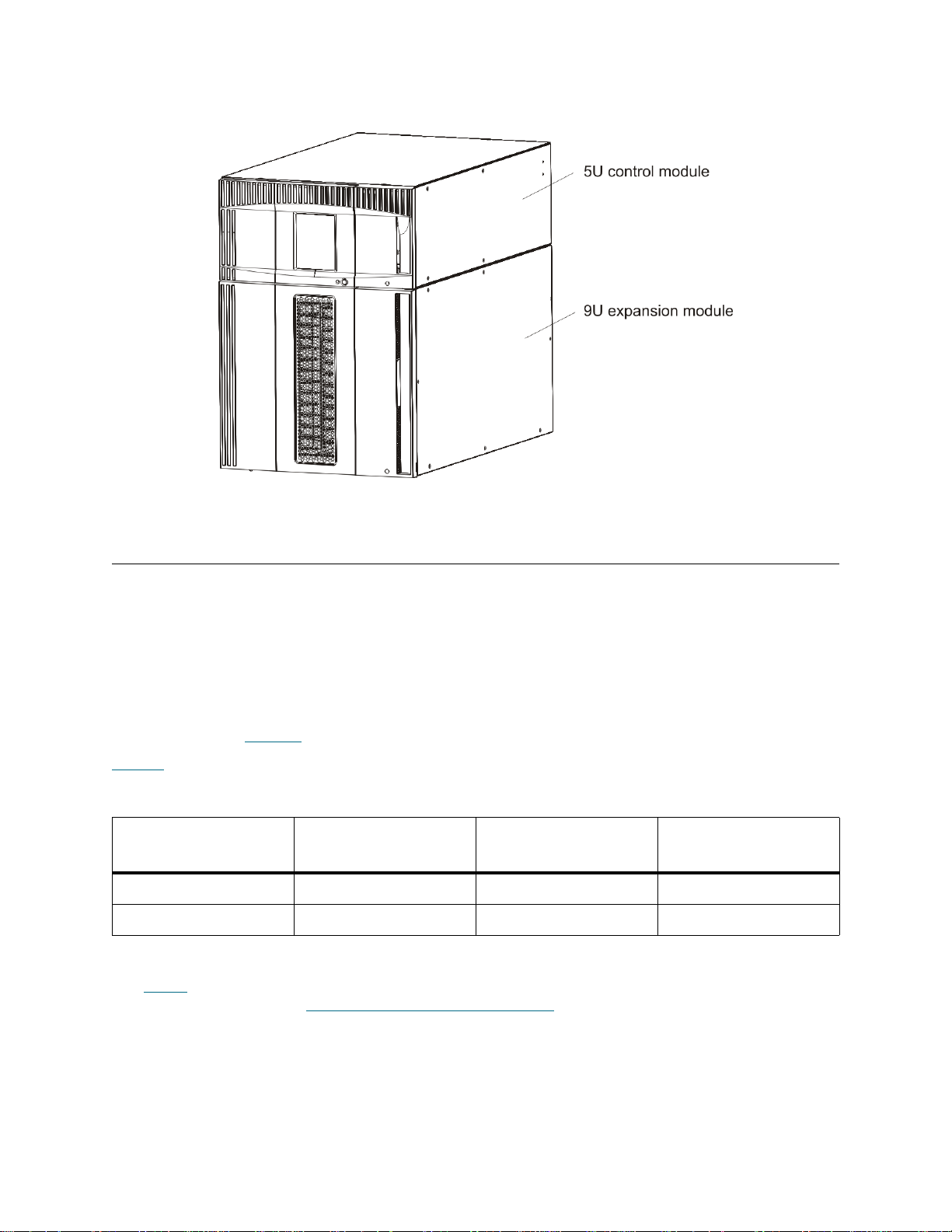
Figure 2 14U Library Configuration (5U Control Module Plus One 9U Expansion Module)
Modules
Tandberg StorageLibrary T128 libraries are modular, an d you can increase the size of the 5U library at any
time. The base systems for the Tandberg StorageLibrary T128 library are as follows:
• A 5U library, consisting of a control module
• A 14U library, consisting of a 5U control module and a 9U expansion module
Expansion modules provide additional capacity as your stor age and tape drive requirements change. If you
have a stand-alone 5U control module, you can add a 9U expansion module to increase the size of your
library to 14U. See Figure 3
Table 1
Table 1 Available Library Configurations
Each module has a specific number of fixed storage slots, I/E station slots, and tape drive slots available.
See Table
and replacing modules, see Installing, Removing, and Replacing
shows the specifications for the available library configurations.
Library Configuration
5U 1, 236, 36 1, 2
14U 1, 636, 128 2, 4
on page 168 for more information on module capacity. For information on installing, removing,
on page 5 for an illustration of library scalability.
Minimum, Maximum
Tape Drives
Minimum, Maximum
Tape Slots
on page 83.
Minimum, Maximum
Power Supplies
4 Description
WARNING
ALL LIBRARIES MAY BE INSTALLED IN A RACK HAVING A MAIN
PROTECTIVE EARTHING (GROUNDING) TERMINAL, AND POWER
MUST BE SUPPLIED VIA AN INDUSTRIAL PLUG AND
SOCKET-OUTLET AND/OR AN APPLIANCE COUPLER COMPLYING
WITH IEC 60309 (OR AN EQUIVALENT NATIONAL STANDARD) AND
HAVING A PROTECTIVE EARTH (GROUND) CONDUCTOR WITH A
CROSS SECTIONAL AREA OF AT LEAST 1.5 MM
T O ENSURE PROPER AIRFLOW AND ACCESS SPACE, ALLOW 60 CM
(24 INCHES) IN THE FRONT AND BACK OF THE LIBRARY.
2
(14 AWG).
5U Control Module
The 5U control module is required in any Tandberg StorageLibrary T128 library configuration. The 5U
control module contains the robotic controls, library control blade (LCB) , and touch screen di splay. The 5U
control module also contains an import/export (I/E) station, fixed storage slots, tape drives, and at least one
power supply.
9U Expansion Modules
A 9U expansion module is a supplementary module that can be stacked above or below the 5U control
module (The recommended (but not required) placement of the 9U expansion module is below the 5U
control module). The expansion module contains fixed storage slots, tape drive slots, and power supply
slots. The I/E stations on the expansion module are included and may be configured as storage.
If an expansion module contains only cartridges, all power is derived from the control module.
Stackability
The two base systems for the Tandberg StorageLibrary T128 are the 5U library, consisting of a 5U
stand-alone control module, and the 14U librar y, con sisting of a 5U control module and a 9U expansion
module. In addition, a 9U expansion module can be added to an existing 5U library to expand the size of
the library to 14U, which is the maximum rack height of the library. Figure 3
stackability of the library.
Figure 3 5U and 14U Library Configurations
on page 5 illustrates the
Tandberg StorageLibrary T128 User’s Guide 5
Unused Storage Slots
Each library configuration contains a limited number of slots that are not accessible to the robot.
In any library configuration, the picker cannot access the bottom two slots in each column in the lowest
module in the stack due to the fact that there is not enough clearance at the bottom of the library for the
robotic picker. The slot counts in this User’s Manual do not include these unusable slots. When bulkloading
the library, do not insert storage or cleaning tapes into the bottom two rows of the lowest module in the
library configuration. For information on bulkloading, see Bulkloading
on page 59.
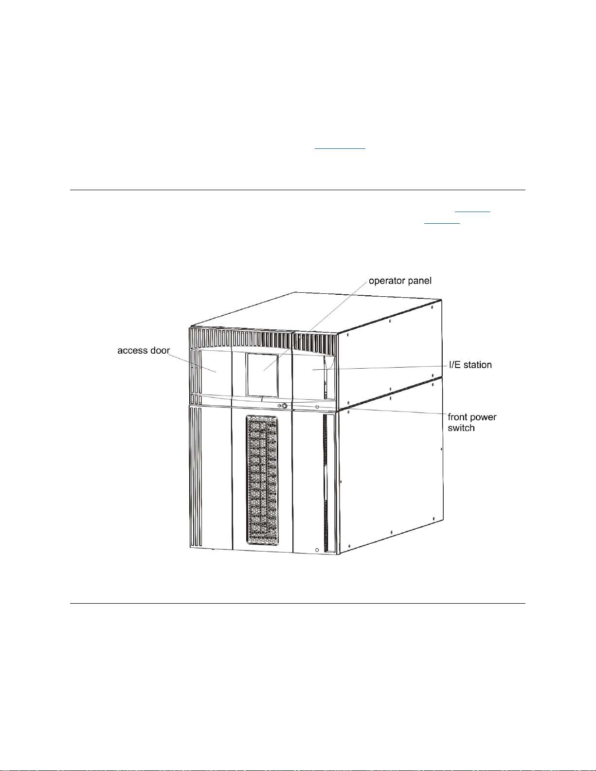
Front Panel Components
The Tandberg StorageLibrary T128 library is made up of physical hardware components. Figure 4 on
page 6 shows the front panel components of the library. The paragraphs following Figure 4
components in detail.
Figure 4 Front Panel Components
describe the
Access Door
The access door allows access to the internal components of the library. Each control module and
expansion module has an access door. In most cases, you will not need to access the library through this
door except when you want to bulkload or unload cartridges from the library.
The access door is locked by the I/E station door. To open the access door, you must first open the I/E
station door. If you want to prohibit access to the library, which is recommended for security reasons, lock
the I/E station door. This keeps unauthorized users from accessing tape cartridges.
6 Description

You can lock and unlock the I/E station door u sing commands on the Operations menu. If necessary, you
can also lock and unlock the I/E station door manually, using a T10 TORX screwdriver. For more information
on these methods of locking and unlocking the I/E station door, see Locking and Un locking the I/E Stations
on page 66.
If the access door is opened, the library is not available for use. When an access door (on any module) is
opened, all in-progress motion commands are stopped, and the picker slowly lowers to the bottom of the
library. When the access door is closed, the library returns any media in the picker to its original slot and
also performs a library inventory.
CAUTION
CARE SHOULD BE TAKEN TO AVOID OPENING THE ACCESS DOOR
DURING ROBOTIC OPERATIONS SINCE THE ROBOT WILL STOP
IMMEDIATELY AND WILL FAIL TO COMPLETE THE CURRENT
OPERATION.
I/E Station
I/E stations enable importing and exporting cartridges with minimal interr uption of normal library operations.
I/E stations are located on the front of the control module and on th e front of expansio n module s . A 5U I/E
station has a capacity of six cartridges within a removable magazine. A 9U I/E station has a capacity of 12
cartridges within two removable magazines.
The I/E stations can also be configured as storage as well as become part of a logical division of library
resources known as a partition. The I/E station is shared among all partitions, but the I/E station slots are
owned by one partition at a time. When an I/E station slot is assigned to a partition, only that partition can
access that slot.
Operator Panel
The operator panel is the touch screen display device upon which the graphical user interface (GUI)
appears. The operator panel is located on the access door of the control module. The libr ary operations and
service functions are performed from this screen. The GUI is also accessible through a remote web client.
For more information on the library user interfaces, see Understanding the User Interface
on page 21.
Front Power Switch
Turning off the front power switch turns off the robot and operator panel, but power still runs to the power
supplies. Use the front power switch to manually reboot or shut down the library. See Shutting Down or
Restarting the Library on page 67 for instructions on how to shut down or restart the library safely.
Back Panel Components
Figure 5 on page 8 shows the back panel components of the library. The paragraphs following Figure 5
describe the components in detail.
Tandberg StorageLibrary T128 User’s Guide 7
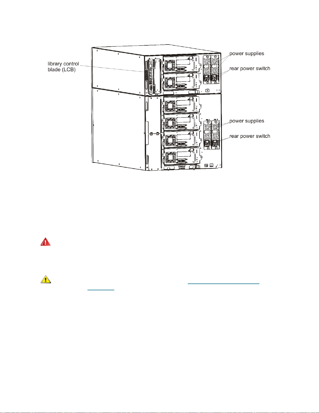
Figure 5 Tandberg StorageLibrary T128 Back Panel Components
Rear Power Switches
Rear power switches are located on each power supply. Turning off the rear power switch on a power supply
removes all power from the library. The rear power switches should be used in all emergency and service
situations.
WARNING
CAUTION
TURN OFF THE REAR POWER SWITCH WHENEVER YOU ARE
SERVICING THE LIBRARY. IN THE EVENT OF DANGER TO
PERSONNEL OR PROPERTY, IMMEDIATELY TURN OFF THE REAR
POWER SWITCH AND REMOVE ALL POWER CORDS.
Except in emergencies, use the shutdown procedure before
switching off the rear power switch. See Shutting Down or Rest artin g
the Library on page 67 for instructions on how to shut down the
library.
Power System
The library supports single and redundant power configur ations. The single power configuration has a single
AC line input and single DC power supply. The redundant configuration has dual AC line input and dua l DC
power supplies.
If you have redundant power supplies, you can hot swap a power supply (power to the library remains on
while you exchange the hardware), and you can hot add power supplies to other modules (power to the
library remains on while you are adding the hardware).
8 Description

WARNING
THE POWER OUTLET MUST BE AVAILABLE NEAR THE LIBRARY
AND MUST BE EASILY ACCESSIBLE.
CAUTION
must have at least one power supply for every four drives. You can
add a redundant power supply to each module. Installing one power
supply in one module and another power supply in another module
does not provide redundant power; the two power supplies must
reside in the same module.
The power system consists of the following components:
• Power supply
• AC power cord
The power supply has three light-emitting diodes (LEDs) that provide status information. These LED status
indicators are green and blue in color.
• Green represents AC OK or DC OK.
• Blue represents swap-mode power status.
The control module and each expansion module that contains drives
Figure 6
Power Supply LEDs
on page 10 shows the power system LEDs. For more information on the behavior of the LEDs, see
on page 161
Tandberg StorageLibrary T128 User’s Guide 9
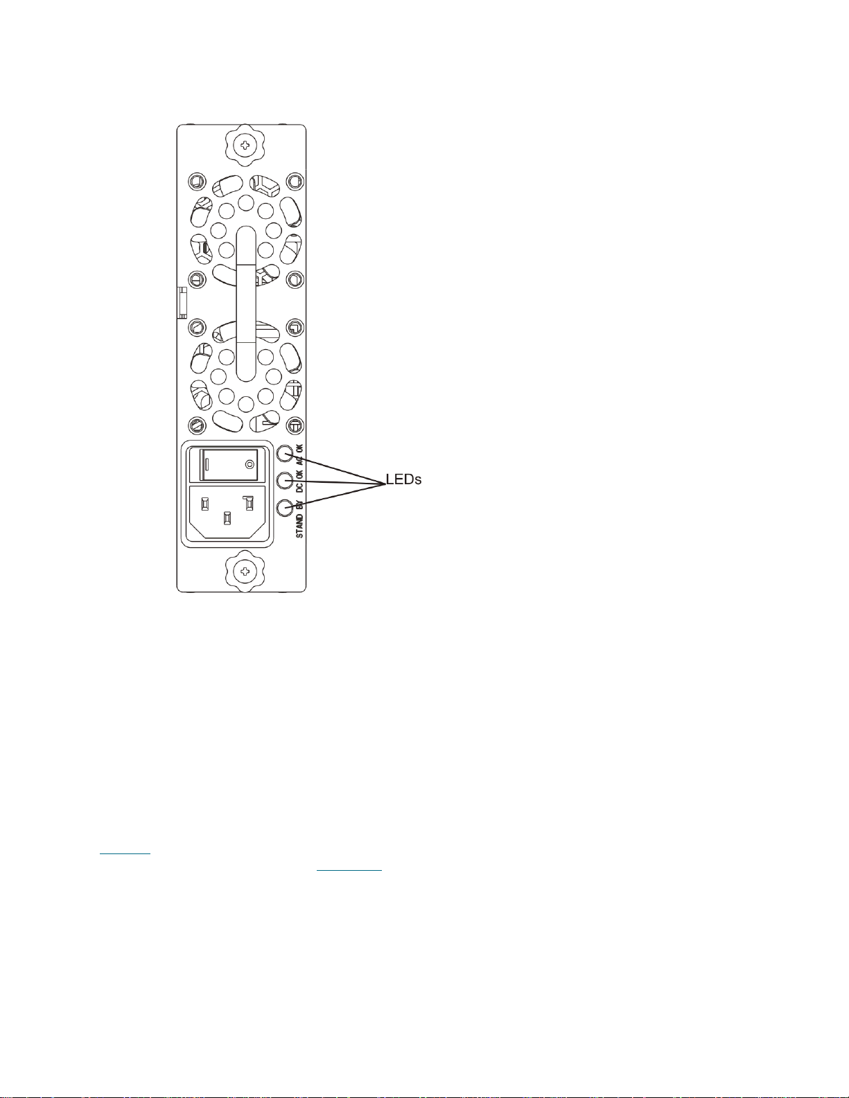
Figure 6 Power System LEDs
Library Control Blade
The library control blade (LCB) manages the entire library, including the operator panel and picker
assembly, and is responsible for running system tests to ensure that the library is functioning properly.
The LCB indicates its status with three LED Reliability, Availability, and Serviceability (RAS) status
indicators. These indicators are green, amber, and blue in color.
• Green represents processor status.
• Amber represents health status.
• Blue represents power-control status.
Figure 7
the behavior of the LCB LEDs, see LCB LEDs
10 Description
on page 11 shows the location of the LCB components, including LEDs. For more information on
on page 158.

Figure 7 Library Control Blade LEDs
Robotic System and Barcode Scanner
The robotic system identifies and moves the cartridges between the storage slots, tape drives, and the I/E
station. The robotic arm (picker) has picker fingers that enable it to grab tape cartridges an d move them into
positions along X, Y, and Z motion coordinates. The robotic system and the barcode scanner work together
to identify the locations of resources within the library.
Each tape cartridge must contain a barcode that the barcode scanner reads during the inventory process.
During the inventory process, the barcode scanner reads the fiducial labels to identify the types of
magazines and tape drives that are installed in the library.
Every tape cartridge must have a unique machine-readable barcode attached to it. Tape cartridges cannot
have duplicate barcode labels. This barcode identifies the cartridge. The library stores th e physical location
of the tape cartridge in an inventory database. All library or host reque sts typically reference the location of
the tape cartridges based on this barcode number. Barcode labels are mandatory and must adhere to
specific standards. For more information on barcodes, see Working With Cartridges and Barcodes
163.
Tandberg StorageLibrary T128 User’s Guide 11
on page

Tape Drive Support
Tandberg StorageLibrary T128 libraries support the following tape drives:
• RoHS-compliant LTO-3 SCSI and Fibre Channel (FC) tape drives. RoHS-compliant LTO-3 FC tape
drives allow FC speed configurations up to 4GB.
• Linear Tape Open-GEN 2 (LTO-2) SCSI and Fibre Channel ( FC) tape drives. The supported LTO-2
tape drives are not compliant with the Restriction of Hazardous Substances (RoHS) directive.
Note
Mixed connectivity (using both SCSI and FC tape drives) is supported in Tandberg StorageLibrary T128
libraries. However, only one type of tape drive can be used in any one partition. LTO FC tape drives can be
directly attached to hosts or the Storage Area Network (SAN). LTO SCSI tape drives are attached directly
to the host. For information on partitions, see Partitions
Details about tape drive support include:
• Every library configuration must contain at least one tape drive.
• 5U modules can hold a maximum of two tape drives.
• 9U modules can hold a maximum of four tape drives.
Tape drives are installed into tape drive slots in the rear of the library. If a tape drive slot is empty, a filler
plate covers the empty tape drive slots to prevent debris from ente ring the library. Tape d rives are shipped
filling the tape drive slots from the bottom to the top of the library, but the tape drives can be reinstalled in
any available tape drive slot.
Note
For information on adding tape drives, see Adding a Tape Drive
A single Tandberg StorageLibrary T128 library can contain all LTO-2 tape
drives or all LTO-3 tape drives, but not both.
on page 14.
Drive filler panels must be in place for the library to operate at normal speed.
on page 149.
Library Features
This section describes several features of Tandberg StorageLibrary T128 libraries.
Licensable Features
In Tandberg StorageLibrary T128 libraries, LTO storage slots are licensed for use. The following situations
may require you to enter a license key:
• During configuration of the library.
• During a feature upgrade.
• To activate additional storage slots in your current configuration.
• To replace the control module. License keys are tied to the serial number of the control module. If
you replace the control module, you will need a new license key.
12 Description

Details about licensable features include:
• License keys can be used only once and cannot be transferred to another library.
• License keys do not expire.
• A given license key can encode several features.
• License keys are absolute values that can only increase licensed features.
For example, if you have a 5U control module with 9U expansion module (12 8 slot) config uration,
and you want to increase the storage capacity of the library from the 82 slots that you activated at
the time of purchase up to the maximum 128 slots for the configu ration, you will need a COD license
key with 128 slots licensed.
• Once you install a license key, you cannot remove it without re-initializing the system. However,
entering a new license key does not require re-initializing the library. See Shutting Down or
Restarting the Library on page 67 for more information on re-initializing the library
• The number of licensed slots can never decrease.
• The license key is associated with the serial number of the 5U control module. If you must replace
your control module for some reason, you will need to request a replacement license key from
Tandberg Data.
• The library control blade (LCB) compact flash card contains information about your library
configuration. If you must replace your LCB flash card, you will need to request a replacement
license key from Tandberg Data.
CAUTION
While you are entering a license key, backup operations may be
interrupted.
Capacity-On-Demand (COD)
The library ships with a minimum of 36 active slots. At any time, the COD feature allows you to enable the
inactive storage slots within a library by using COD license keys. COD license keys are available in 46-slot
increments. For information on obtaining a COD license key, see Obtaining a Capacity-On-Demand License
Key on page 44.
To see your library’s current configuration and slot availability, you can open the Library Configuration
report from the Reports menu of the web client interface. Table 2
licensable slots that are available in the different library configurations.
Note
Once you receive the firmware license key, enter the key via the operator panel of the library. When the
license key is entered, the total number of available slots in the library increases. An expansion module may
be required, depending on your configuration. See Applying L icense Keys
on activating a licensed feature.
The numbers of licensable slots listed in Table 2 are adjusted for the unusable
slots in each configuration. The number of physical slots in the 5U and 14U
configurations is always ten more than the number of licensable slots.
on page 14 shows the number of
on page 43 for more information
Tandberg StorageLibrary T128 User’s Guide 13

Table 2 Licensed Slots Per Library Configuration
Library Configuration Number of Usable Licensed Slots
5U 36
14U 36, 82, 128
Partitions
Partitions are virtual sections within a library that present the appearance of multiple, separate librar ies for
purposes of file management, access by multiple users, or dedication to one or more host applications.
Organizing the library into partitions divides the resources into virtual sections. If one of the r esources is not
available due to a failure or other cause, the other partitions and their assigned components are still
available. Partitions can also be used to control access to portions of the library by granting permissions to
user accounts to access certain partitions.
For more information on partitions, see Working With Partitions
on page 34.
Logical Unit Numbering (LUN)
Logical unit numbering (LUN) is the means by which the tape drives send medium changer commands from
a host to the library controller via the tape drive’s Library Drive Interface (LDI) port and its sled’s Controller
Area Network (CAN) interface. The purpose of the LUN interf ace is to eliminate the re quireme nt for a host
interface on the library control blade, thereby reducing system cost.
User Interface
The operator panel is located on the fro nt door of the control module and allows users to work lo cally on the
library via the user interface. The web client interface allows users to view and perform library functions from
remote sites and is accessible through a browser. The operator panel and web client interface contain a
similar user interface and functionality.
See Understanding the User Interface
web client interface.
on page 21 for more information about the operator panel and the
Control Path Modification
The control path tape drive is used to connect a partition to a host application. Only one tape drive can be
selected as the control path at one time. By default, the first tape drive assi gned to a par tition is designated
the control path. In the event that the control path connectio n to the host a pplicatio n fails, you can select a
new control path for the partition.
Support for WORM
Tandberg StorageLibrary T128 tape libraries support WORM (wri te once, read many) technolo gy in LTO-3
tape drives. WORM allows non-rewriteable and non-erasable data to be written and provides extra data
security by prohibiting accidental data erasure. The WORM feature is supported whene ver you use WORM
cartridges.
14 Description

System Requirements
The Tandberg StorageLibrary T128 web client interface supports the following browsers:
•Microsoft
• Firefox, version 1.0.6 and above
®
Internet Explorer™ version 6.0 and above
Tandberg StorageLibrary T128 User’s Guide 15

16 Description

Setting Up the Library
This chapter provides an overview of the steps required to unpack, set up, and install the Tandberg
StorageLibrary T128 library.
For basic library setup instructions, see the Quic k Star t Gu ide. A copy o f th e Quic k St ar t Guide is included
in the product box with your library.
For complete installation instructions, see Installing, Removing, and Replacin g
on page 83.
Unpacking the Library
This section includes instructions on unpacking your library. Follow the information in this section so as not
to harm yourself or the library and its components.
WARNING
Unpacking and Inspecting
1 Unpack the library.
Following the unpacking instructions that came with the library, remove the library exterior packaging
but leave the library in the bottom packaging tray.
WITHOUT TAPE DRIVES, TAPE CARTRIDGES, OR POWER
SUPPLIES, A 5U CONTROL MODULE WEIGHS APPROXIMATELY 58
LBS. A 9U EXPANSION MODULE, WITHOUT TAPE DRIVES, T APE
CARTRIDGES, OR POWER SUPPLIES, EXCEEDS 65 LBS. TO AVOID
SERIOUS INJURY, TWO PEOPLE ARE REQUIRED TO SAFELY LIFT
THE MODULES INTO POSITION.
CAUTION
2 Check the contents of the package against the packing slip.
3 Remove the interior packaging.
After you have removed the packaging sleeve and while the library is still sitting in the bottom packaging
tray, remove all packaging from the interior of the library.
Tandberg StorageLibrary T128 User’s Guide 17
Save all packing materials in case you need to move or ship the
library in the future.

CAUTION
4 Remove as many tape drives as you can reach.
While the library is still sitting in the bottom packaging tray, remove the tape drives to reduce the weight
of the library. Remove as many tape drives as you can reach.You may not be able to remove the tape
drive in the lowest drive bay at this time.
Be sure to remove the following items:
• The strap holding the robot in place. Release the velcro and unhook
each end of the strap.
• All cardboard and foam surrounding the robot.
For information about removing tape drives, see Adding, Removing, and Replacing Tape Drives
page 148.
5 Remove the library from the bottom packaging tray.
WARNING
6 Remove the remaining tape drive.
Remove the remaining tape drive from the bottom of the library. For information about removin g tape
drives, see Adding, Removing, and Replacing Tape Drives
7 Position the library in an optimal location.
For information on properly placing your library, see Finding a Location
WITHOUT TAPE DRIVES, TAPE CARTRIDGES, OR POWER
SUPPLIES, A 5U CONTROL MODULE WEIGHS APPROXIMATELY 58
LBS. A 9U EXPANSION MODULE, WITHOUT TAPE DRIVES, T APE
CARTRIDGES, OR POWER SUPPLIES, EXCEEDS 65 LBS. TO AVOID
SERIOUS INJURY, TWO PEOPLE ARE REQUIRED TO SAFELY LIFT
THE MODULES INTO POSITION.
on page 148.
.
Finding a Location
on
To avoid damage, the library must be positioned in a stable location. See the System, Safety, and
Regulatory Information Guide for more information on finding an optimal location for your library.
WARNING
Details on positioning the library include:
• Make sure a power source (only of the type marked on the product label) is available. See
Specifications
• Route any cables to avoid walking on them or pi nching them with ite ms placed on or against them.
Pay particular attention to the cord at the wall receptacle and the point where the cord exits from
the library.
• Make sure that objects will not fall and liquids will not spill into the library’s chassis through
openings.
18 Setting Up the Library
THE POWER OUTLET MUST BE AVAILABLE NEAR THE LIBRARY
AND MUST BE EASILY ACCESSIBLE.
on page 167 for power requirements.

Initial Setup Road Map
Once you have unpacked the library and moved it into position, you are ready to install the library and
prepare it for use. This section provides a road map for the initial installation of the library. The Tandberg
StorageLibrary T128 library includes one control module and may include one 9U expansion module. The
list below indicates the proper sequence for setting up each library configuratio n that is currently available.
References to the installation, setup, and configuration procedures are included in the road map.
WARNING
1 Follow the detailed preparation and installation instructions for your library configuration.
If your library configuration is: Then see these installation instructions:
5U — a stand-alone control module Installing a Stand-Alone 5U Control Module
14U — one control module and one 9U
expansion module
2 Install the tape drives.
For instructions, see Adding, Removing, and Replacing Tape Drives
ALL LIBRARIES MAY BE INSTALLED IN A RACK HAVING A MAIN
PROTECTIVE EARTHING (GROUNDING) TERMINAL, AND POWER
MUST BE SUPPLIED VIA AN INDUSTRIAL PLUG AND
SOCKET-OUTLET AND/OR AN APPLIANCE COUPLER COMPLYING
WITH IEC 60309 (OR AN EQUIVALENT NATIONAL STANDARD) AND
HAVING A PROTECTIVE EARTH (GROUND) CONDUCTOR WITH A
CROSS SECTIONAL AREA OF AT LEAST 1.5 MM
T O ENSURE PROPER AIRFLOW AND ACCESS SPACE, ALLOW 60 CM
(24 INCHES) IN THE FRONT AND BACK OF THE LIBRARY.
page 89
Installing a New 14U Library Configuration
page 90
2
(14 AWG).
on page 148.
on
on
3 Install the power supplies.
For instructions, see Adding, Removing, and Replacing Power Supplies
4 Install the library control blade (LCB).
If the library control blade (LCB) is not already installed, install it in the control module. For instructions,
see Removing and Replacing the Library Control Blade and LCB Compact Flash Card
5 Install the data path communications and network cables.
Two sets of cabling instructions are provided: one for SCSI tape drives an d one for Fibre Channel (FC)
tape drives. A library can have both SCSI and FC drives. For cabling instructions, see Cabling the
Library on page 84 or the Quick Start Guide.
6 Turn on power to the library.
Press the power switch on the front of the library once.
7 Configure the library.
Configure network settings, set date and time, create us er accounts, configure Import/export (I/E) slots,
and perform other tasks that allow you to begin using the library. For instructions, see Config uring Your
Library on page 29.
Tandberg StorageLibrary T128 User’s Guide 19
on page 136.
on page 133.

If you need to license additional storage slots, contact technical suppor t for license keys to activate the
additional slots. For contact information, see Getting More Information or Help
instructions on licensing storage slots, see Applying License Keys
8 Load tape cartridges into the library.
You can use the I/E commands to import tape cartridges into the library or perform an initial bulkload of
the library.
When bulkloading the library, do not insert storage or cleaning tapes into the bottom two rows of the
lowest module in the library configuration . In an y libr ar y con fig ur a tion , th e pick er can no t acc es s the
bottom two slots in each column in the lowest module in the stack due to the fact that there is not enough
clearance at the bottom of the library for the robotic picker.
on page 43.
on page 2. For
For instructions on importing tape cartridges, see Importing Media
bulkloading, see Bulkloading
Removing, and Replacing on page 83.
9 Connect to the host application.
Set up the connection to the library host application. If your host application inventories the location of
each tape cartridge in the library, open the host application and perform a reinventory to sync the logical
inventory with the physical inventory of the library.
For instructions, see your host application documentation.
10 Register the library.
For more information about registering the library, see Registering the Library
11 Run the library.
You are now ready to start using your library. For informa tion about using your library, see Running Your
Library on page 55 and the library’s online Help.
on page 59. For complete installation instructions, see Installing,
on page 58. For information on
on page 54.
Downloading Drivers
You can find drivers for your library at www.tandberg.com.
20 Setting Up the Library

Understanding the User Interface
The user interface of Tandberg StorageLibrary T128 libraries is available in two formats: th e operator panel
and the web client. Operations on the Tandberg StorageLibrary T128 library can be performed locally on
the control module using the operator panel or remotely on your computer using the web client. Similar
functionality with common elements is used for both formats.
Both the web client and operator panel user interfaces are re quired to operate the library. Some functionality
is only available through the web client, and some fu nctionality is only available through the operator panel.
However, using the web client rather than the operator panel to perfor m library operation s (when possible)
is recommended.
You must disable web browser popup blockers to use the web client interface and the library’s online Help.
Add the Tandberg StorageLibrary T128 Internet Pro tocol (IP) a ddress to the list o f trusted/allowed sites on
your Tandberg StorageLibrary T128-supported browser, so the web client pages will automatically refresh.
Common User Interface Elements
The user interface consists of four areas:
• Header — appears on every screen and contains the company logo, product name, and the three
main navigation buttons. The main navigation buttons are:
• Home — home page (default is Capacity View)
• Help — context-sensitive Help for the active screen
• Logout — ability to log out
• Title/Menu — appears below the header and provides the library/partition name and access to the
menu tabs on the main screen. On subsequent screens, this area is a single line an d provides the
screen name.
• Main — main content area of the screen.
• Health/Navigation — provides information about the “health” of the library by means of three
subsystem status buttons: Library, Drives, and Media. See System Summary and Subsystem
Status for more information on the subsystem buttons.
Figure 8
Tandberg StorageLibrary T128 User’s Guide 21
on page 22 and Figure 9 on page 22 show the operator panel and the web client interfaces.

Figure 8 Operator Panel User Interface
Figure 9 Web Client User Interface
22 Understanding the User Interface

System Summary and Subsystem Status
You can quickly gauge the health of the library by observing the color of the three subsystem status buttons
located at the bottom of the home page. These buttons provide quick access to information about the
"health" of the library for faster recovery if problems occur. You can select the buttons to view Reliability,
Availability, and Serviceability (RAS) tickets that report problems in the subsystems.
The three subsystems are:
• Library — This subsystem represents the following: connectivity, control, cooling, power, and
robotics.
• Drives — This subsystem represents tape drive components, such as tape drives, tape drive
firmware, and tape drive sleds.
• Media — This subsystem represents media compone nt s, su ch as cart rid ge s an d ba rcode labels.
Each button has three states indicated by color. The three states are:
• Green — no RAS tickets exist or, if any tickets do exist, they have all been closed.
• Yellow — unopened and open low or high priority RAS tickets.
• Red — unopened and open urgent RAS tickets.
If the color of a subsystem button is red or yellow, you can click the button to display the All RAS Tickets
screen. This screen lists library, drives, or media RAS tickets, depending on which button was selected.
RAS tickets display in the order in which they were created, starting with the most recent.
You can also open the All RAS Tickets screen by selecting Tools > All RAS Tickets. See Troubleshooting
on page 153 for more information about RAS tickets.
Home Page
The home page is common to both the operator panel and the web client inter face. From the home page,
there are two modes of navigation to acces s the use r interface screens: tabs on the Capacity View and
categorized function links on the Library View.
Capacity View
The Capacity View screen is the default view of the library and provides tabular data on the cap acity of the
library's partitions, slots, and drives. You can use the Capacity View to see a quick summary of the capacity
of the library. The current user's login privileges determine the information that is displayed in the Capacity
View.
Details about Capacity View include:
• Upon logging in, users see the first partition (in alphabetical order) to which they have access.
• On the operator panel, if users have access to more than one partition, they can n aviga te to other
partitions using arrows next to the partition na m e at the top of th e scr ee n.
For more information about user privileges, see User Privileges
Accounts on page 48.
on page 26 and Working With User
Users can toggle from the Capacity View to the Library View.
Library View
The Library View provides a graphical representation of the library as well as another mode of navigation.
Use the Library View to navigate through the library. The control module is labeled with “hot” areas that
can be selected to access the functions for each area of the library. You will find the same navigation buttons
on the Library View as on the Capacity View.
Tandberg StorageLibrary T128 User’s Guide 23

On the web client, the Library View represents the actual configuration of the user’s library, including the
order in which the modules are stacked. Administrative users can toggle to the Capacity View from the
Library View.
Note
On the operator panel, only administrative users can access the Library View
toggle button and screen.
Operator Panel
The operator panel is physically attached to the front door of the control module. The user interface appears
on the touch-screen LCD display of the operator panel for executing basic library management functions.
Audible feedback, or “key click” sounds, are generated whe n a user presses a button on the operator panel.
Users can choose to disable the audible feedback. See Configuring System Settings
on page 53.
Operator Panel Keyboards
When a user touches a text box requiring data entry, a keyboard screen appears. The alpha, numeric, or
month keyboard appears, depending on the type of input field touched. All alphab etic character entrie s are
lower case. The text box appears at the top of screen, and the numbers/characters appear as they are
entered. Pressing 123 opens the numeric keyboard.
Web Client
The web client HTTP interface is similar to the operator panel user interface. The web client interface is
accessible from supported web browsers. See System Requirements
supported browsers.
on page 15 for information about
To manage the library from a remote web client interface, you must set up the library’s initial network
configuration from the operator panel touch screen. See Managing the Network
on setting the network configuration settings for remote use.
on page 50 for information
Menu Trees
The following four menus organize commands into logical groupings:
•The Setup menu consists of commands that you can use to set up and configure various aspects
of the library, including partitions, I/E station slots, cleaning slots, control paths, network settings,
drive IDs, users, notifications, date and ti me, licenses, e-mail, and library registration.
•The Operations menu consists of commands that enable users to change the library’s mode of
operations, import and export cartridges, load and unload tape drives, move media, and log off.
Administrative users can also access commands to lock or unlock the I/E station and to shut the
library down.
•The Tools menu consists of commands that you can use to maintain your library such as viewing
RAS Tickets, generating diagnostic logs, identifying drives, configuring the internal ne twork, saving
and restoring the library configuration, setting syst em and se curity settings, and u pdating firmwar e.
•The Reports menu (web client only) consists of summaries of library information.
A hidden Service menu is available to service users with the appropriate login information.
The menus vary somewhat between the web client and operator panel user interfaces. Administrative users
have access to all menu commands, but users' privileges are more limited.
24 Understanding the User Interface
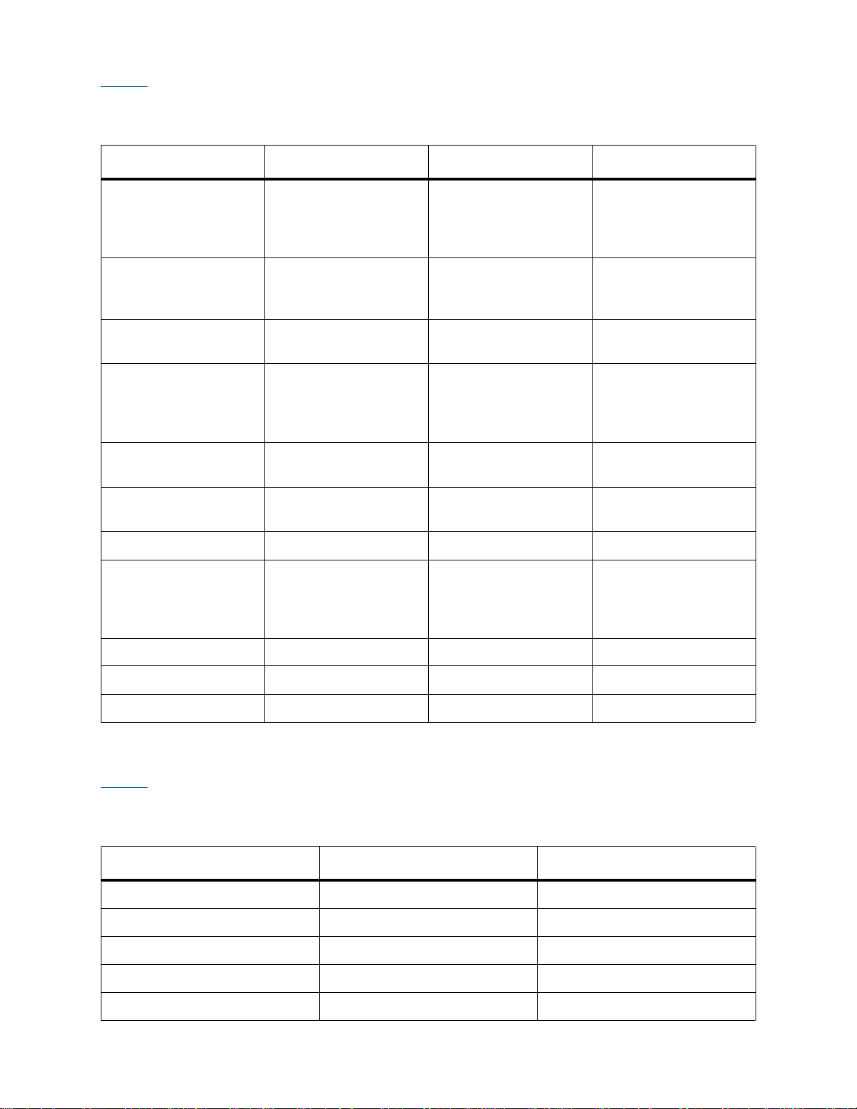
Table 3 lists the web client menus. Some menu commands are available only to users with administrative
privileges.
Table 3 Web Client Menus
Setup Menu* Operations Menu Tools Menu* Reports Menu
Setup Wizard* Media
All RAS Tickets* System Information
>Move
>Import
>Export
Partitions* Cleaning Media
Capture Snapshot* Library Configuration
>Import
>Export
Cleaning Slots* Partitions
>Change Mode
I/E Station Slots* Drive
Save/Restore
Configuration*
Identify Drives* Logged in Users
>Load
>Unload
>Change Mode
Drive IDs* I/E Station
Drive Operations* All Slots
Lock/Unlock*
Control Path* System Shutdown* Update Library
Firmware*
License* Log Out
Notification*
>Setup*
>E-mail Account*
>Contact Information*
Network Settings
About Tandberg
StorageLibrary T128
Users*
Date and Time*
Register Library*
*Administrative users only.
Table 4 lists the operator panel menus. Some menu commands are available only to users with
administrative privileges.
Table 4 Operator Panel Menus
Setup Menu* Operations Menu Tools Menu*
Setup Wizard* Move Media All RAS Tickets *
Create Partitions* Import Media Capture Snapshot*
Delete Partitions* Export Media Drive Management*
Create Users* Import Cleaning Media Drive Info*
Modify Users* Export Cleaning Media About Library
Tandberg StorageLibrary T128 User’s Guide 25
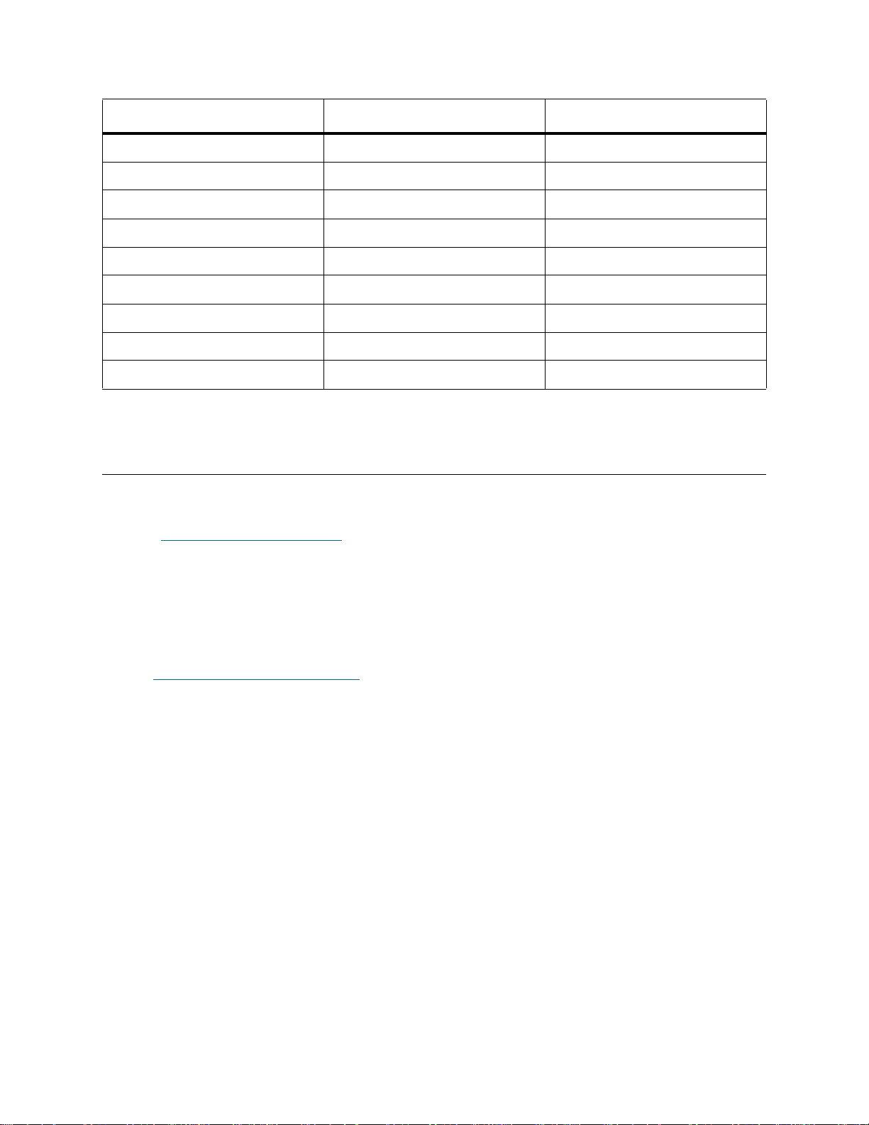
Table 4 Operator Panel Menus (Continued)
Setup Menu* Operations Menu Tools Menu*
Cleaning Slots* Change Partition Mode Internal Network*
I/E Stations* Load Drive System Settings*
Drive IDs* Unload Drive Security*
Notification* Change Drive Mode
Licenses* I/E St ation Lock/Unlock*
Network Configuration* Shutdown*
Date and Time*
Network Management*
Control Path*
*Administrative users only.
User Privileges
User privilege levels are manually assigned to user accounts created within the library. Controlling access
to screens and operations within the library preserves the integrity of the lib rary an d th e data that is stored
in it. See Working With User A ccounts
Three types of users are defined in Tandberg StorageLibrary T128 libraries:
• Administrative users have access to the entire physical library and all of its partitions. The library
ships with a default administrative user account. The user name for the default administrative user
account is admin and the password is password. You cannot modify or delete the user name for
the default administrative account, but you can modify the password. If you mi splace the password
for the default administrative account, contact Technical Support. For contact information, see
Getting More Information or Help
• Users have access to one or more assigned partitions and can perform functio ns within a partition,
such as performing cartridge and tape drive operations. A user cannot perform operations that
affect the physical library, such as creating or deleting pa rt itio ns .
• A service user has access to the entire physical library and all of its partitions as well as to a hidden
Service menu that includes service and diagnostic tools. Each library has only one service user
account.
Details on user privileges include:
• The library can contain a maximum of eighteen user accounts (user or administrative or both),
including the default administrative user account.
• A maximum of eighteen user (user or administrative or both) sessions can be active at one time.
on page 48 for more information on setting user privilege levels.
on page 2.
• The same user can be logged in from multiple locations.
• Clicking the close button (X) in the upper-right corner of the web client interface closes the browser
window but does not log the user or administrative user out.
• A screen saver is invoked after 10 minutes of inactivity on the operator pa nel. (The web client
interface does not use a screen saver.) The use r or administrative user who is inactive between 10
and 30 minutes returns to the last accessed screen after resuming activity on the operator panel.
26 Understanding the User Interface

• All users are logged out automatically after a configurable period of inactivity. The default timeout
period is 30 minutes, but users with administrative privileges can change this to a value from 15
minutes to 480 minutes (eight hours). See Configuring System Settings
• When a service user logs in, all other active users are automatically logged out.
on page 53.
User Access
See Table 3 on page 25 for the web client menu tree and privilege level information. See Table 4 on
page 25 for the operator panel menu tree and privilege level information.
Tandberg StorageLibrary T128 User’s Guide 27

28 Understanding the User Interface

Configuring Your Library
Once you have installed the hardware as described in Setting Up the Librar y on page 1 7, you are ready to
configure your library’s settings. A Setup Wizard helps you get started configuring your lib rary, and menu
commands on both the operator panel and the web client allow you to reconfigure your library at any time.
CAUTION
Always save the library configuration after modifying configurable
items. This will allow you to restore the most current settings if
necessary. See About Saving and Restoring the Configuration
page 155.
on
About the Setup Wizard
When you first power on the library, the operator panel displays the Setup Wizard, which walks you through
the initial configuration of the library's basic operational settings, including network settings that enable you
to access the library from the web client.
You must begin the Setup Wizard on the operator panel, but you have the option to complete the Setup
Wizard on the web client. The Setup Wizard prompts you to enter the n etwork settings that allow the web
client to access the library. Once this step is complete, you must choose to either complete the wizard locally
(on the operator panel) or remotely (on the web client). The on-screen instructions recommend that you
choose to complete the wizard on the web client. The web client Setup Wizard offers more options.
While completing the Setup Wizard remotely is recommended, you may need to begin using the library
locally immediately. In this case, you can complete the Setup Wizard on the operator panel or even cancel
out of the Setup Wizard and allow the library to run on the default configuration settings.
Administrative users can always return to the Setup Wizard or use commands on the Setup and
Operations tabs to modify all library settings, including network settings.
For additional information, see Using the Setup Wizard
on page 30.
Using the Default Administrative User Account
When you power on the library for the first time, you do not need to log in to use the operator panel. You
can start using the Setup Wizard immediately. After the initial setup session on the operator panel,
however, you will need to log in to the operator panel as well as the web client.
Tandberg StorageLibrary T128 User’s Guide 29

The library ships with a default administrative user account. The user name on the account is admin and
the password is password. When you see the Login screen on the operator panel or web client, type
admin in the User Name text box and password in the Password text box. As soon as the initial setup is
complete, you should change the password on the default administrative account. For information on
changing passwords, see Modifying User Accounts
on page 49.
Note
Note
You cannot delete the default administrative user account or modify the user
name. You can, however, change the password.
If you misplace the password for the default admin istrative account, contact
Technical Support. For contact information, see Gettin g More Information or
Help on page 2.
Completing the Library Configuration With Menu Commands
The Setup Wizard is an aid to assist you with the initial configuration of the library. You can always return
to the Setup Wizard by selecting it from the Setup tab on the operator panel or the Setup menu on the web
client.
The Setup Wizard, however, contains only a subset of configuration tasks. The operator panel tabs and
web client menus provide access to most configuration options that are included in the Setup Wizard and
many that are not. Once the initial Setup Wizard session is complete, administrative users can choose
whichever method is most convenient or necessary for modifying library settings.
The following topics cover using the Setup Wizard as well as Setup and Operations commands to
configure the library. Paths to open the appropriate screens on both the operator panel and the web client
are given for each task. For the operator panel, the paths refer to the navigation tabs at the top of the home
page. For the web client, the paths refer to the menus.
For the menu trees on both the operator panel and web client, see Menu Trees
on page 24.
Note
Power cycling (powering the library on and off) is not necessary to configure
the library.
Using the Setup Wizard
The Setup Wizard simplifies the process of configuring the library. When you fir st power on the library , the
operator panel displays the Setup Wizard.
The recommended procedure for using the Setup Wizard for the initial configuration is as follows:
1 Turn on the library and begin using the Setup Wizard on the operator panel. Be sure to configure
network settings.
2 When the Setup Wizard screen text prompts you to choose Local or Remote, choose Remote.
3 Log out of the operator panel.
4 Using the default administrative account, log in to the web client. Type admin in the User Name text
box and password in the Password text box.
5 Complete the Setup Wizard screens on the web client interface.
See also About the Setup Wizard
on page 29.
30 Configuring Your Library

Details on using the Setup Wizard include:
• The only time that you do not need to log in to the library is when the Setup Wizard appears on the
operator panel the first time the library is powered on.
• After a timeout period of one hour, the Setup Wizard will close, and you will be logged out of the
library. Use the default administrative user account to log in on the operator panel.
• If you time out of the Setup Wizard or do not complete all the Setup Wizard screens, the library
will apply the default configuration settings plus whatever modifications (if any) you made.
• You can only configure network settings on the operator panel, a nd you cannot log in to the lib rary
from the web client until you have configured network settings.
• You can always return to the Setup Wizard whenever you are logged in to either the operator pan el
or the web client.
• Any administrative users you create will also be able to use the Setup Wizard as well as Setup and
Operations menu commands to reconfigure the library.
• If necessary, you can cancel out of the Setup Wizard on the operator panel and begin using the
library locally with the default settings in place. If you accept the default network configuration
settings, you will not be able to access the library remotely from the web client. You can, however,
return to the Setup Wizard on the operator panel at any time and modify network and other
settings.
The default configuration settings are as follows:
• License keys: 36 slots, minimum. The total number depends on number of pr e-activated slots
purchased.
• Network settings: DHCP enabled
• Import/export (I/E) station slots: 6
• Cleaning cartridge slots: 0
• Partitions: The default is one partition if your library contains only SCSI tape drives or only
Fibre Channel (FC) tape drives. If your library contains both SCSI and FC tape drives, the
default is two partitions. The library automatically groups the FC t ape drives in one pa rtition and
the SCSI tape drives in another . The library does not support mixed t ape drive types in a single
partition.
Setup Wizard Tasks
As you work through the Setup Wizard screens, follow the on-screen instructions.
The Setup Wizard screens contains only a subset of all configuration options. The Setup and Operations
menus contain most configuration options, including those in the Setup Wizard. This chapter includes
detailed descriptions of the configuration tasks, including how and when to access them through the Setup
and Operations menus.
• Welcome (operator panel) — Welcomes you to the Setup Wizard.
• Hardware Installation (operator pa nel) — Reminds you to install tape drives and the Ethernet
cable.
• Setting the Date and Time
on your library.
(operator panel and web client) — Allows you to set the date and time
• Configuring Network Settings
remote access using the web client.
• Choosing the Interface: Local or Remote
on the operator panel or on the web client.
Tandberg StorageLibrary T128 User’s Guide 31
(operator panel) — Allows you to enter your network settings for
(operator panel) — Allows you to choose to continue

If you choose Local, the wizard proceeds on the operator panel. If you choose Remote, the wizard
presents a Confirm Remote screen. Exit the operator panel, log in to the web client and select
Setup > Setup Wizard to resume configuring your library.
• Applying License Keys
features.
• Configuring Cleaning Slots
cleaning slots. Configuring at least one cleaning slot enables the AutoClean feature. For more
information about the AutoClean feature, see About Cleaning Tape Drives
• Configuring I/E Station Slots
import/export (I/E) station slots.
• Working With Partitions
partitions.
• Confirm Settings (operator panel and web client) — Allows you to confirm your library settings.
The operator panel displays the Setup Wizard the first time you power on. After that, administr ative users
can return to the Setup Wizard any time they are logged in.
CAUTION
Always take a library snapshot and save the library configuration
after modifying configurable items. If modifying items results in
issues, the library snapshot will help Support personnel to
troubleshoot the problem. Saving the library configuration will allow
you to restore the most current settings if necessary. For more
information on taking a library snap sh ot and saving and rest oring the
library configuration, see Troubleshooting
(operator panel and web client) — Allows you to enter keys for licensed
(operator panel and web client) — Allows you to configure de dicated
on page 63.
(operator panel and web client) — Allows you to configure
(opera tor panel and web client) — Allows you to set the number of libra ry
on page 153.
Note
The paths to open the appropriate screens are as follows:
• From the web client, select Setup > Setup Wizard.
• From the operator panel, select Setup > Setup Wizard.
Setup Wizard operations cannot be performed concurrently by multiple
administrative users logged in from different locations. You can access the
screens, but you cannot apply changes while another administrative user is
performing the same operation.
Choosing the Interface: Local or Remote
The Setup Wizard: Local or Remote screens a re parts of the oper ator panel Setup Wizard only. Use the
second Setup Wizard: Local or Remote screen to select whether yo u want to finish configur ing the library
using the local operator panel or the remote web client.
The Web Client button is grayed out if the Internet Protocol (IP) address has not been configured .
The network configuration settings are the only settings that must be configured using the operator panel.
Once the IP address is set, you can access the Setup Wizard from the web client and configure the
remaining settings.
Remote Configuration
The Setup Wizard: Remote Configuration screen pr ovides the information necessary to acce ss the web
client to complete the initial configuration of the library.
32 Configuring Your Library

The screen lists the IP address of the library. Use this IP address to access the web client using a Web
browser. When typing the IP address into the Web browser, make sure to precede it with http://; for
example, http://123.123.123.123.
Configuring Network Settings
The Setup Wizard: Network Configuration screen allows you to configure network settings that allow
remote access to the library from the web client. Administrative users can also modify the network settings
by selecting Setup > Network Config on the operator panel. You cannot modify these settings on the web
client.
If you modify the IP address on the Setup Wizard: Network Configuration screen, you will need to type
the new IP address in the Address field of your Web browser to access the web client.
Note
• Library Name is the network name you want to assign to the library. The library name is limited to
12 alphanumeric characters and dashes (-).
• Dynamic Host Configuration Protocol (DHCP) defaults to enabled, setting the library to enable
triggers via DHCP to automatically configure the library network settings. Enable makes the IP
Address, Subnet Mask, and Default Gateway text boxes unavailable. Disable makes the IP
Address, Subnet Mask, and Default Gateway text boxes available for you to manually set the
library network settings.
• IP Address is the IP address of the library. This text box is available only if DHCP is disabled.
• Default Gateway is the IP address of the default gateway for your portion of the Ethernet network.
This text box is available only if DHCP is disabled.
• Subnet Mask text box is available only if DHCP is disabled.
The IP Address, Default Gateway, and Subnet Mask text boxes are limited to numeri c characters and
cannot have a value greater than 255.
Make sure that the library is connected to the network before modifying
network settings. If the Ethernet cable is not installed properly, you cannot
configure the network settings. Install one end of the Ethernet cable in the top
Ethernet port located at the back of the library just below the three LEDs. Make
sure the other end of the Ethernet cable is installed in the appropriate LAN port
on your LAN.
Note
You cannot configure the network settings from the web client. The path to ope n the app ropr iate scr een is
as follows:
• From the operator panel, select Setup > Network Config.
Tandberg StorageLibrary T128 User’s Guide 33
Be sure to add your library’s IP address to the list of trusted/allowed sites on
your library-supported browser, so the web client pages automatically refresh.
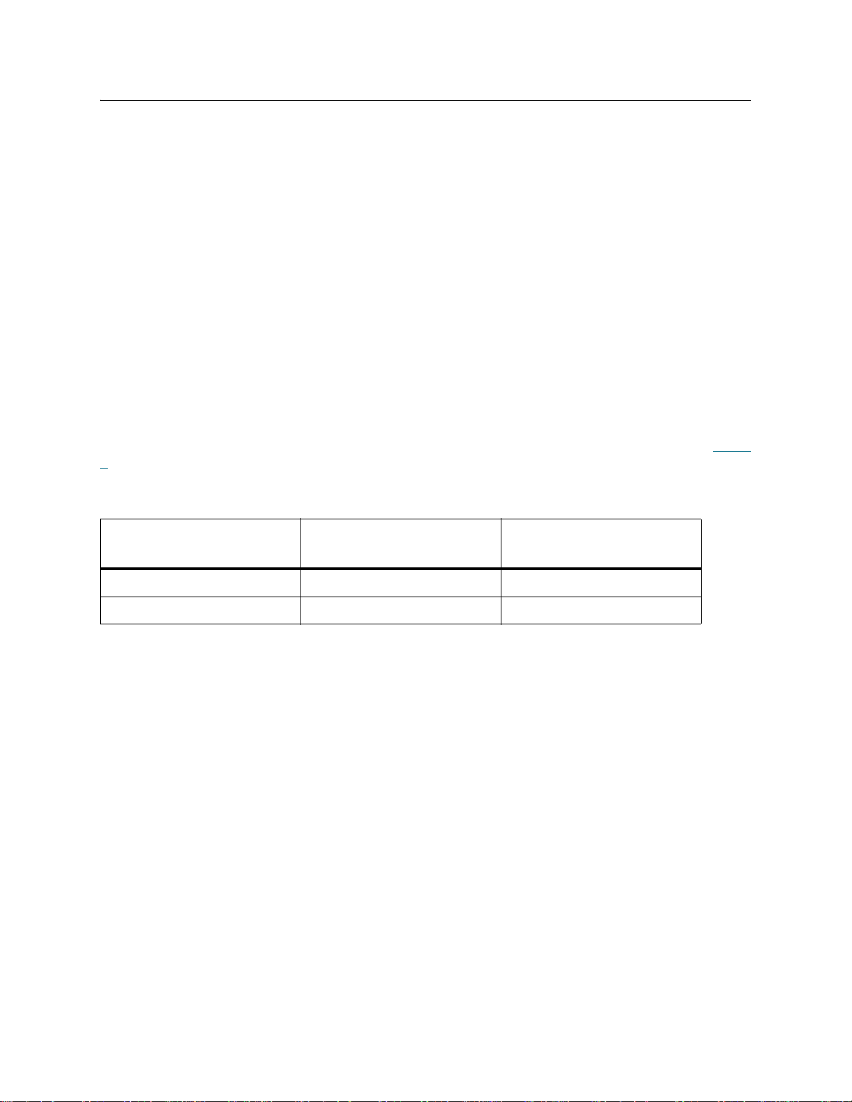
Working With Partitions
The Setup Wizard: Partitioning screens allow administrative users to select the number of new library
partitions to create.
Partitions are virtual sections within a library that present the appearance of multiple, separate librar ies for
purposes of file management, access by multiple users, or dedication to one or more host applications. The
library must contain at least one unassigned tape drive and slot to create a partition.
At any time after the initial configuration of the library, administrative users can add to the number o f existing
partitions by selecting Setup > Partitions on the web client or Setup > Create Partitions on the operator
panel.
There are two ways to create partitions:
• Automatically — assigns library resources proportionately among the partitions, grouping tape
drives according to their interface type (FC or SCSI). You can create partitions automatically on
either the operator panel or the web client. When you automatically create partitions, you add to the
number of existing partitions.
• Manually — an administrative user creates partitions one at a time. Creating partitions manually
gives you more control over resource allocation. You can create partitions ma nually only on the web
client. When you manually create partitions, you add to the number of existing partitions.
The maximum number of partitions that can be create d is equal to the number of drives in the library. Table
5 shows the possible number of partitions that can be created for ea ch of the available library configurations.
Table 5 Number of Partitions Supported
Available Configurations
5U 1, 2 1, 2
14U 1, 61, 6
Details on partitions include:
• Administrative users can create, modify, delete, and control access to all partitions. Users can be
given access to only certain partitions and denied access to others.
• Partition names are limited to 12 lower-case alphanumeric characters and underscores ( _ ).
• The maximum number of partitions that can be created is equal to the number of drives in the
library.
• At minimum, a partition consists of one tape drive and one slot. The tape drive or slot cannot be
shared with another partition (an exception to the sharing restrictions a re cleaning tapes, which can
be shared among all partitions).
• I/E station slots are shared between all partitions. Partitions take temporar y ownership of I/E station
slots when importing or exporting tape cartridges.
Tape Drives
Minimum, Maximum
Partitions
Minimum, Maximum
• By default, the library has one partition if your library contains one tape drive type (SCSI or FC). If
your library contains both SCSI and FC tape drives, the default is two partitions. The library
automatically groups the FC tape drives in one partition and the SCSI tape drives in another. The
library does not support mixed tape drive types in a single partition.
34 Configuring Your Library

CAUTION
Before permanently removing an expansion module fro m your library ,
you need to perform a set of configuration operations that includes
deleting all partitions. See Deleting Partitions
Removing 9U Expansion Modules From an Existing Library
107.
on page 37 and
on page
Automatically Creating Partitions
At any time after the initial configuration of the library, administrative users can add to the number o f existing
partitions by using the automatic partitioning process. Automatic partitioning assigns available library
resources proportionately among the partitions, grouping tape drives according to their interface type
(FC or SCSI).
The library must contain at least one unassigned tape drive and one un assigned slot to automatically create
a partition. If no unallocated tape drives or slots exist, you must modify or delete one or more partitions to
free up resources. For more information, see Modifying Partitions
page 37.
The maximum number of partitions that you can create is equal to the number of drives in the library. On
the Automatically Create Partitions screen, you can select the number of partitions to create, from a
minimum of one to a maximum that equals the number of tape drives in your library.
If your library contains both FC and SCSI tape drives, you must select at least two partitions on the
Automatically Create Partitions screen. The library does not support mixing FC and SCSI tape drive
interfaces within the same partition. When you select two or more partitions, the library automatically groups
the FC tape drives and SCSI tape drives and assigns them to different partitions.
on page 36 and Deleting Partitions on
To manually create partitions, use the web client. See Manually Creating Partitions
Note
The paths to open the appropriate screens are as follows:
• From the web client, select Setup > Partitions.
• From the operator panel, select Setup > Create Partitions.
This operation cannot be performed concurrently by multiple administrative
users logged in from different locations. You can access the screen, but you
cannot apply changes while another administrative user is performing the same
operation.
on page 35.
Manually Creating Partitions
Using the web client, administrative users can manually create addition al partitions any time after the in itial
configuration of the library. The maximum number of partitions that can be created is equal to the number
of drives in the library.
The library must contain at least one unassigned tape drive an d slot to create a partition. If no tape drives
or slots are available, you must modify or delete an existing partition to free up resources. For more
information, see Modifying Partitions
The library does not support mixing FC and SCSI tape drives in one partition. If your library contains both
FC and SCSI tape drives, you need to create more than one partition so that you can assign the FC and
SCSI tape drives to different partitions.
on page 36 and Deleting Partitions on page 37.
Tandberg StorageLibrary T128 User’s Guide 35

When creating partitions manually, you need to provide the following information:
• Emulation Type — the type of library that the partition is emulating
• Partition Name — limited to a maximum of 12 lower-case alphanumeric characters and
underscores ( _ )
• Media Barcode Format — defaults to Extended. The available options are as follows:
• Extended
• Length must be from 5 to 16 characters.
• Standard Six
• Length must be either 6 or 8 characters.
• Six Plus
• Length must be 8 characters.
• Number of Slots — the number of storage slots allocated to the new partition
• Drives — the tape drive or drives assigned to the partition
Note
Note
Note
You cannot create partitions manually from the operator panel. The path to open th e approp riate scr een is:
• From the web client, select Setup > Partitions.
Bold column headings in the table can be sorted. For example, selecting the
Location column heading will sort by location coordinates.
Before creating partitions, verify that all tape drives are unloaded and that all
cartridges are in their appropriate storage slot location. For information on
unloading tape drives, see Unloading Tape Drives
Creating Partitions operations cannot be performed concurrently by multiple
administrative users logged in from differen t loca tio ns . You can access the
screen, but you cannot apply changes while another administrative user is
performing the same operation.
on page 62
Modifying Partitions
Using the web client, administrative users can modify partition settings any time after the partitio n is created.
The tape drive set as the control path for a particular partition cannot be deleted from that partition. The
check box associated with the control path is grayed out. For more infor mation on se tting the contr ol path,
see Modifying the Control Path
on page 43.
Also, the library does not support mixing FC and SCSI tape drives in one partition. Assign just one tape drive
type to a given partition.
The library automatically takes the partition offline before modifying it and places the partition back online
after it is modified.
When modifying a partition, you may need to provide the following information:
• Emulation Type — the type of library that the partition is emulating.
• Partition Name — limited to a maximum of 12 lower-case alphanumeric characters and
underscores ( _ ).
36 Configuring Your Library

• Media Barcode Format — defaults to Extended. See Manually Creating Partitions on page 35 for
descriptions of available options.
• Number of Slots — the number of tape cartridge slots allocated to the partition.
• Drives — the tape drive or drives assigned to the partition.
Note
Note
You cannot modify partitions manually from the operator pane l. The path to open the appropriate screen is:
• From the web client, select Setup > Partitions.
Bold column headings in the table can be sorted. For example, selecting the
Location column heading will sort by location coordinates.
Before modifying partitions, verify that all tape drives are unloaded and that all
cartridges are in their appropriate storage slot location. For information on
unloading tape drives, see Unloading Tape Drives
on page 62
Deleting Partitions
A partition can be deleted when it is no longer needed or when I/E station slots need to be reconfigured.
Unload all tape drives and export all cartridges assigned to the partition that is to be deleted. After exporting
the cartridges, remove them from the I/E station. For more information, see Unloading Tape Drives
62 and Exporting Media
Details about deleting partitions include the following:
• After a partition is deleted, its resources (for example, tape drives and slots) become available and
can be reassigned to new or existing partitions .
• Deleting a partition does not delete users assigned to that pa rtition. However, if these users are not
assigned to other partitions, they will not be able to perform library operations. See Changing
Partition Access on page 38.
on page 60.
on page
Note
Note
You may need to modify settings in your host application as a result of deleting
a partition. See your host application documentation.
This operation cannot be performed concurrently by multiple administrative
users logged in from different locations. You can access the screen, but you
cannot apply changes while another administrative user is performing the same
operation.
Deleting Partitions Before Permanently Removing Expansion Modules
Because partitions extend across the library’s physical modules and share resources, the library will report
errors if you permanently remove an expansion module fro m your library without first deleting partitions and
modifying shared resources such as cleaning slots and I/E slots.
See Removing 9U Expansion Modules From an Existing Library
preparing your library for the permanent removal of an expansion module. The following is a high-level
summary of the preparation process:
• You may find it helpful to review your library’s current configur ation before removing the expansion
module. See Viewing the Library Configuration
Tandberg StorageLibrary T128 User’s Guide 37
on page 69.
on page 107 for detailed instructions on

• Using your I/E station, export all the tape cartridges from your library. See Exporting Media on page
60.
• Reduce the number of cleaning slots in the libr ary to 0. You can d esignate new cleanin g slots after
the expansion module has been remove d. See Configuring Cleaning Slots
• Delete all partitions in the library. You can create new partitions after the expansion module has
been removed.
on page 39.
• Make sure that your library control module contains an I/E station. See Configuring I/E Station Slots
on page 40.
The paths to open the appropriate screens are as follows:
• From the web client, select Setup > Partitions.
• From the operator panel, select Setup > Delete Partitions.
Changing Partition Access
An administrative user can control which partitions a specified user can access by modifying the user's
account. Also, any user assigned to a partition that ha s bee n deleted can be reassig ned to ot her partitions.
To change partition access, you must provide the following information:
• Password — a unique password that can be viewed and modified by the administrative user.
• Privilege Level — determines the user’s access privileges. See User Privileges
more information on user privilege levels.
• Partition Access — the partitions to which the user has access.
The paths to open the appropriate screens are as follows:
• From the web client, select Setup > Users.
• From the operator panel, select Setup > Modify Users.
on page 26 for
Changing Partition Modes
This topic focuses on using the library user interface, not the host application, to change partition mode.
Changing a partition mode using the library user interface may affect your host application. See your host
application documentation for more information.
There are two partition modes: online and offline.
• Online — the default partition mode. This is the normal operating conditi on for the partition. In this
mode, the robotics are enabled and all host application commands are processed.
• Offline — the partition does not process any host application commands. If the partition is taken
offline, the physical library and other partitio ns ar e no t af fected.
You can take the physical library or any of its partitions online or offline. Some operations require that the
partition be offline. You can take a partition offline r ather than the entire libra ry so as to minimize disruption
of library operations. You can manually change the partition mode to online or offline from the operator panel
or the web client.
When you are changing the partition mode, be aware of the following:
• When you access the Change Partition Mode screens, you will see only partitions to which you
have been given access.
•The Online/Offline buttons toggle between states.
38 Configuring Your Library

• If a partition is in use, the Online/Offline button is grayed out.
• Set the button to Online to take either the physical library or a partition (depen d ing on th e curre n t
view) to an online state, which is the normal operating condition. In this mode, the robotics are
enabled and all host commands are processed.
• Set the button to Offline to take either the physical library or a partition (depending on the current
view) to an offline state. If only the physical library is taken offline, the library’s partitions will not
process robotics commands, even though they are online. If only a partition is taken offline, neither
the physical library nor the other partitions are affected.
Note
Note
The paths to open the appropriate screens are as follows:
• From the web client, select Operations > Partitions > Change Mode.
• From the operator panel, select Operations > Partition Mode.
Some maintenance activities require that the entire library be taken offline. To
take the library offline, change the mode of all partitions from online to offline.
When changing the partition mode from online to offline, all host application
commands in progress at the start of the mode change are completed.
Configuring Cleaning Slots
Cleaning slots are used to store cleaning cartridges that are used to clean tape drives. The Setup Wizard:
Cleaning Slot Configuration screens prompt you to enter the number of cleaning slots (if any) you want
to designate for your library. You can also access the Cleaning Slot Configuration screens directly on the
operator panel and web client.
The Setup Wizard d efault configuration settings include zero dedicated cleaning slots. Configuring at least
one cleaning slot enables the library’s AutoClean feature. When AutoClean is enabled, the library allows
you to import and export cleaning cartridges. When a tape drive needs cleaning, it notifies the library. If
AutoClean is enabled, the library automatically cleans the tape drive using a cleaning cartridge lo aded in a
cleaning slot.
Note
Cleaning slots are not assigned to specific partitions. They are shared by all partitions within a library. Each
partition can access cleaning cartridges located in the dedicated cleaning slots.
The maximum number of cleaning slots that can be configured is equal to the number of unassigned slots,
up to a maximum of four. For example, if only two slots are available in the library, the maximum number of
cleaning slots is two. To disable AutoClean, configure zero cleaning slots.
If the library has been previously configured, the number of cleaning slots that are currently configu red
appears on the screen. If you decrease the number of cleaning slots from what was p reviously configured ,
the extra slots become available for use.
Administrative users can configure cleaning slots during the initial library configuration and at any time after
that, as long as unassigned slots are available. If no slots are available in the library, you must modify or
delete a partition to free up slots. For more information see Modifying Partitions
Partitions on page 37.
Tandberg StorageLibrary T128 User’s Guide 39
If you configure zero I/E station slots, you will not be able to import or export
cleaning cartridges. Y ou will need to bulkload these cartridges. See Configuring
I/E Station Slots on page 40 and Bulkloading on page 59.
on page 36 and Deleting

Administrative users can also clean tape drives manually. For information, see Manually Cleaning Tape
Drives on page 66.
Note
Note
The paths to open the appropriate screens are as follows:
• From the web client, select Setup > Cleaning Slots.
• From the operator panel, select Setup > Cleaning Slots.
Cleaning slots are not visible to the host application. To choose host-based
cleaning, do not configure any cleaning slots, and configure your host
application to manage cleaning tape drives. Configuring cleaning slots on the
library may affect the host application. See your host application
documentation for information.
This operation should not be performed concurrently by multiple administrative
users logged in from different locations. You can access the screen, but you
cannot apply changes while another administrative user is performing the same
operation.
Configuring I/E Station Slots
I/E station slots are used to import and export tape cartridges into and out of the library without disrupting
normal library operations. The Setup Wizard: I/E Station screens allow you to configure I/E Station slots.
Administrative users can also configure these slots by selecting Setup > I/E Station Slots on either the
operator panel or the web client.
Note
Each control module contains six I/E station slots, and each expansion module contains 12 I/E stati on slots.
The available library configurations support a minimum of six I/E slots in the 5U library to a maximum of 18
I/E slots in the 14U library configuration. You can also choose to configure zero I/E station slots and use all
slots in all I/E stations for tape cartridge storage. For more information on configuring zero I/E slots, see
Configuring Zero I/E Station Slots
Each I/E station (6-slot or 12-slot) is configured as a complete unit. When configuring an I/E station,
configure all the slots in the I/E station the same way: all storage or all I/E slots.
If the library consists of a 5U control module, all six I/E station slots must be configured either as storage or
as I/E station slots. A 14U library consists of a 5U control module (with six I/E station slots) and a 9U
expansion module (with 12 station slots). All 12 of the slots in the 9U e xpansion module must be configured
the same way, as either I/E station slots or storage slots. Therefore, a 14U library can contain a minimum
of six and a maximum of 18 dedicated I/E station slots. Table 6
slots available per library for all base library configurations.
Details on configuring I/E station slots include:
• Before configuring I/E station slots, remove all tape cartridges from the I/E station slots.
• The default number of dedicated I/E slots is six. If you accept the Setup Wizard default
configuration settings, six I/E slots will be created in the control module.
I/E station slots can only be configured if no partitions have already been
configured. If partitions are configured, you must delete the partitions before
configuring I/E station slots. See Deleting Partitions
on page 41.
on page 37.
on page 41 lists the number of I/E station
• If you increase the size of your 5U library by adding a 9U expansion module, the I/E stations in the
new module will be storage slots by default. You can select to reconfigure these slots as I/E slots.
40 Configuring Your Library

• Based on the number of I/E slots you configure, the library automatically determines which I/E
stations to configure as I/E slots and which to configure as storage.
• The library configures I/E slots in the control module I/E station first and then works outward to
the I/E station in the 9U expansion module. I/E stations in expansion modules below the control
module have precedence over I/E stations in expansion modules above the control module.
• All slots in an I/E station must be configured the same way: as either storage or I/E slots. For
this reason, if your library includes a 9U expansion module and you configure an even numbe r
of I/E slots greater than six, the 5U control module I/E station may be configured automatica lly
as storage.
• If the I/E station is configured as data storage slots, its door is always locked. For information on
unlocking I/E stations, see Locking and Unlocking the I/E Stations
• I/E station slots are shared by all partitions within a library.
• To identify how a specific I/E station magazine is configured, view the Library Location report
available from the Reports menu. See Viewing the Library Configuration
on page 66.
on page 69.
Configuring Zero I/E Station Slots
Configuring zero I/E slots increases the number of storage slots in your library but has the following
consequences:
• You will not be able to use the I/E station to import and export tape cartridges, including cleaning
media.
• You will be required to open the library access door to bulkload and unload tape cartridges,
disrupting library operations. See Bulkloading
• You will not be able to perform any of the following drive management operations:
• Updating tape drive firmware with a FUP tape
• Creating FUP tapes
• Erasing FUP tapes
• Manually cleaning tape drives with a cleaning cartridge
For more information on using the I/E station to import and export media, see Runnin g Your Library
55. For more information on performing drive management operations, see Updating Lib rary and Tape Drive
Firmware on page 73.
Table 6 Number of I/E Station Slots Available Per Base System
Library
Configuration
5U 16––16
14U 16112218
5U Control Module 9U Expansion Module Library Total
I/E Stations I/E Slots I/E Stations I/E Slots I/E Stations I/E Slots
on page 59.
on page
CAUTION
Tandberg StorageLibrary T128 User’s Guide 41
Configuring I/E station slots with cartridges already loaded
compromises data security. First, remove cartridges from the I/E
station and then configure the I/E station slots.

Note
This operation cannot be performed concurrently by multiple administrative
users logged in from different locations. You can access the screen, but you
cannot apply changes while another administrative user is performing the same
operation.
Note
The paths to open the appropriate screens are as follows:
• From the web client, select Setup Wizard > I/E Station Slots.
• From the operator panel, select Setup Wizard > I/E Station Slots.
If you configure zero I/E station slots, you will not be able to perform I/E Station
and drive management functions.
Setting Tape Drive Parameters
You can change the following parameters:
• The SCSI ID for a SCSI-attached tape drive
• The loop IDs, topology connection mode, and interface speed for a Fibre-attached tape drive
Note
If the affected partition is online, it will be taken offline before the parameters are set, and brought back
online after they are set.
The FC topology connection mode and interface speed can be set through the
web client only, not through the operator panel user interface.
Each device on a SCSI bus, including the host bus adapter (HBA) needs to have a unique SCSI ID.
Changing the SCSI ID is necessary when there is a duplicate ID on a single bus. Typically, the HBA SCSI
ID is set to 7. For example, if two tape dr ives are connected together on the sam e bus, each tape drive must
have different SCSI IDs and they must be different from the HBA SCSI ID.
For SCSI tape drives, a SCSI ID can be set to a value between 0–15. The library assigns the following
default SCSI IDs to SCSI tape drives:
• 5U control module: 1 and 2
• 9U expansion module: 3, 4, 5, and 6
For FC tape drives:
• The loop ID can be set to a value between 0–125. A unique loop ID is selected by default for all FC
tape drives installed in the library. For example, the tape drive installed in the top drive bay of a 5U
control module is assigned a default loop ID of 61. The tape drive installed in the 5U control
module’s bottom drive bay is assigned a default loop ID of 63.
If you change the default loop IDs, make sure each FC tape drive with a topology setting of Auto
(LN), Loop (L), or Auto (NL) has a unique loop ID.
• The requested topology connection mode can be set to one of the following:
• Auto (LN) — Auto-configure trying L-Port first
• Loop (L) — Force L-Port
• Point to Point — Force N-Port
42 Configuring Your Library

• Auto (NL) — Auto-configure trying N-Port first (default)
• The requested interface speed can be set to Auto (default), 1 Gbs, 2 Gbs, and 4Gbs. If you set the
speed to 4Gbs, a caution message appears informing you that the 4Gbs speed selection may not
be applicable to all FC tape drives installed in the library. Acknowledge the message by clicking OK.
• The screen also displays the actual FC topology connection mode and interface speed. If the
requested topology setting is not supported, the next appropriate setting is negotiated and appear s
in the Actual column. If FC drives are not connected to the host, the negotiated actual settings
appear on the screen as "unknown."
Note
The paths to open the appropriate screens are as follows:
• From the web client, select Setup > Drive IDs.
• From the operator panel, select Setup > Drive IDs.
Bold column headings in the table can be sorted. For example, selecting the
Location column heading will sort by location coordinates.
Modifying the Control Path
The control path tape drive is used to connect a partition to a host application. Only one tape drive can be
selected as the control path at one time. By default, the first tape drive assi gned to a par tition is designated
the control path. In the event that the control path connectio n to the host a pplicatio n fails, you can select a
new control path for the partition.
After you modify the control path, the library will reset the tape drive by changing the drive mode from online
to offline and then back to online.
Note
You may need to modify settings in your host application as a result of
modifying the control path. See your host application documentation.
Note
The paths to open the appropriate screens are as follows:
• From the web client, select Setup > Control Path.
• From the operator panel, select Setup > Control Path.
Bold column headings in the table can be sorted. For example, selecting the
Location column heading will sort by location coordinates.
Applying License Keys
The Setup Wizard: Licensing screen prompts you to enter a license key. You can also access the
Licensing screen directly on the operator panel and web client.
A single license key may be applied to the library during the initial configuration or whenever licensed
features are purchased. If an additional feature is purchased, the new license key will replace the current
license key.
Tandberg StorageLibrary T128 User’s Guide 43
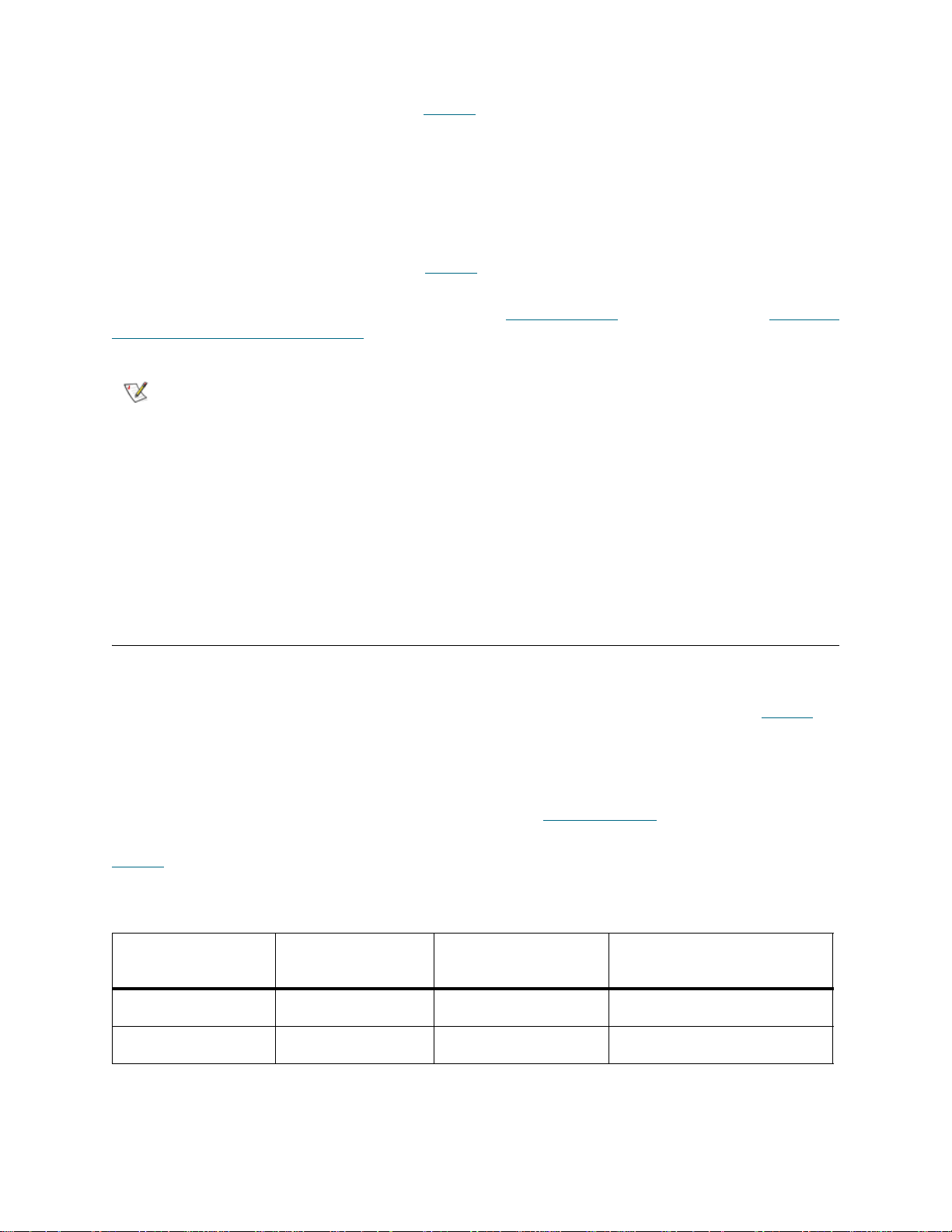
All Tandberg StorageLibrary T128 library configurations ship with the purchased number of slots
pre-activated (always a minimum of 36). See Table 7
slots available for each library configuration.
After the initial purchase, you can increase the number of usable slots in your library by purchasing a
Capacity-On-Demand (COD) license key. COD license keys come in 46-slot increments. For example, a
14U library could have 82 slots licensed (36 + 46 = 82) at the time of the initial purchase. The remainin g 46
slots of the 14U library can be enabled at a later time by purchasing and applying a COD license key. The
full 128 slots would then be enabled and available for use. It is possible to license more slots than are
physically available in the library at the time. In that case, when a 9U expansion module is added, the extra
licensed slots then become available for use. Table 7
for each library configuration.
on page 44 for the number of default pre-activated
on page 44 shows the available COD slot upgrades
For more information about the COD licensed feature, see Libr ary Features
a Capacity-On-Demand License Key below.
Note
You can enter the license key on the Setup Wizard: Licensing screen, and you can also use commands
on the operator panel or web client to directly enter a license key at any time after exiting the Setup
Wizard.The paths to open the appropriate screens are as follows:
• From the web client, select Setup > License.
• From the operator panel, select Setup > Licenses.
This operation should not be performed concurrently by multiple administrative
users logged in from different locations. You can access the screen, but you
cannot apply changes while another administrative user is performing the same
operation.
on page 12. Also, see Obtaining
Obtaining a Capacity-On-Demand License Key
All Tandberg StorageLibrary T128 library configurations ship with the purchased number of slots
pre-activated. The number of available pre-activated slots begins at 36 for all library configurations and
increases in 46-slot increments to a maximum o f 128 slots in th e 14U libra ry configuration . See Tab le 7
the number of default pre-activated slots available for purchase for each library configuration.
After the initial purchase, you can activate any remaining inactive slots in your library by purchasing a COD
license key. Each license key a ctivat es an add itio nal 46 slots in the library. For exam ple, if you purcha se a
14U library with only 82 slots of the maximum 128 slots active at the time of purchase, you can later activate
the remaining 46 slots by purchasing a COD license key. (See Library Features
information about the COD feature.)
on page 12 for more
for
Table 7
configuration
Table 7 Activated Slots Per Available Configuration
44 Configuring Your Library
on page 44 shows the number of slots you can activate with a COD license key for each library
Library
Configuration
5U 36 36 NA
14U 128 36, 82, 128 82, 128
Maximum
Available Slots
Default
Activated Slots
Available
COD Slot Upgrades

When you purchase a COD slot upgrade, Tandberg Data issues you an Authorization Code Certificate
containing a code that enables you to retrieve your COD license key from the Tandberg Data Capacity
Upgrade website. You can then activate your COD slot upgrade by loading the license key on the library
through the operator panel or web client (see Applying License Keys
on page 43).
Details about the COD license key include:
• An authorization code to obtain a license key can be use d on e tim e only.
• A single license key can only be applied once and cannot be transferred to a nother library. The key
is verified when it is applied to the library to make sure it has not been previously used. In addition,
the license key is verified against the library to make sure that it is not allocated for more resources
than what physically exist in the library.
• The license key may contain up to 12 alphanumeric characters. The license key can also contain
the at (@), dash (-), or underscore ( _ ) symbols. Alpha characters must be lowercase. The user
interface automatically converts entries to lowercase.
• The license key is associated with the serial number of the 5U control module. If you must replace
your control module for some reason, you will need to request a replacement license key from
Tandberg Data.
• You will also need to request a replacement license key if you replace your library control blade
(LCB) compact flash card. The LCB compact flash card contains information about your library
configuration, including licensed features.
For contact information, see Getting More Information or Help
on page 2.
To obtain your COD license key for a COD slot upgrade:
1 Contact your Tandberg Data technical sales re pr es en ta tive to subm it you r ord er for a COD slot
upgrade. You can purchase license keys in 46-slot increments. For contact information, see Getting
More Information or Help on page 2.
Upon receipt of your order for a COD slot upgrade, Tandberg Data will ship you an Authorization Code
Certificate containing your COD authorization code.
2 On your library, locate the Serial Number. You will need the Serial Number to retrieve your license key
from the COD website. To view the Serial Number:
• On the operator panel, select Tools > About Library.
- or -
• On the web client, select Reports > About StorageLibrary T128.
3 Access the Tandberg StorageLibrary T128 Capacity Upgrade website at
http://www.license.tandberg.com/t128.
The Capacity Upgrade website allows you to enter your authorization code and your library's Serial
Number.
4 In the Serial Number box, enter your Serial Number.
5 Click Submit.
If you have entered a valid Serial Numbe r, the website prompts you to enter your author ization code for
the COD slot upgrade.
6 Following the on-screen instructions, enter your authorization code.
If you have entered a valid authorization code, the website allows you to retrieve the license key for your
COD slot upgrade.
7 Following the on-screen instructions, retrieve your new license key.
Tandberg StorageLibrary T128 User’s Guide 45

You are now ready to apply the license key to the library, activating your COD upgrade. See Applying
License Keys on page 43.
Setting Customer Contact Information
Administrative users can use the web client to enter contact informa ti on in to th e librar y for the per son who
is the primary customer contact for the library. Keep this information current to expedite the Service process.
Once the customer contact information has been entered, you can view it at any time on the web client or
the operator panel. On the operator panel, you can use the scroll bars on the right and b ottom of the screen
to view all the customer contact information.
When a problem occurs with the library, the contact information is mailed to support@tandberg a long with
RAS ticket information, assuming that the default e-mail notification has been configured. For information
on configuring the default e-mail notification see Creating E-mail Notifications
The customer contact information is used to populate the same fields on the registration page. See
Registering the Library
You can set customer contact information from the web client user interface only, but you can view it from
the operator panel user interface.
The paths to open the appropriate screens are as follows:
• From the web client, select Setup > Notification > Contact Information.
• From the operator panel, select Setup > Notification.
on page 54 for more information on registering the library.
on page 47.
Configuring the Library E-mail Account
The library uses the library e-mail account whenever library e-mail services are used, such as when the
library automatically sends e-mail notifications about library issues.
The Setup — E-mail Account screen contains the following fields:
• SMTP IP Address includes the IP address (for example, 192.16.96.201) of the SMTP server.
Numeric entries are the only valid values for this field.
• Sender Account includes an e-mail address for the library (for example,
"libraryname@mycompany.com"). The library uses this address in the From field of e-mail
messages that it sends out, indicating the originator of the message.
• Use Authentication includes a means to enter the login account name and password for the
library. Selecting the box enables use authentication. Clearing the box disables use authentication.
The following fields are only available if use authentication is enabled:
• Login Account includes the name of a valid account on the SMTP server (for example,
"John.User").
• Password is the password for the account that you specified in the Login Account text box.
You can configure the library e-mail account from the web client user interface only, but you can view e-mail
account information from the operator panel user interface.
The paths to open the appropriate screens are as follows:
• From the web client, select Setup > Notification > E-mail Account.
• From the operator panel, select Setup > Notification.
46 Configuring Your Library

Working With E-mail Notifications
The library can be configured to automatically send e-mail notifications to specified e-mail addresses
whenever an issue of a particular severity level occurs with one of its components.The information in the
e-mail notification provides details about the issue and the library conditions at the time of the error.
Before you can configure e-mail notifications, you must configure the library’s e-mail account so that the
library can send notifications to the designated recipients. See Configuring the Library E-mail Account
page 46 for information on how to configure the e-mail account.
on
See Creating E-mail Notifications
library supports a maximum of 20 e-mail notifications, including the default supp ort e-mail notification.
Note
There are three e-mail notification levels:
• Low Filter — Notifies e-mail recipients of all library issues, including minor, medium-level, and the
most critical issues.
• Medium Filter — Notifies e-mail recipients of medium-level and the most critical issues.
• High Filter — Notifies e-mail recipients of only the most critical issues.
Administrative users can configure the library e-mail account and e-mail notifications. Users can receive
e-mail notifications, but they cannot configur e th e libra r y e-m a il accoun t an d/ or not ifica tio ns .
You can configure e-mail notifications from the web client user interface only, but you can view them from
the operator panel user interface.
The paths to open the appropriate screens are as follows:
• From the web client, select Setup > Notification > Setup.
• From the operator panel, select Setup > Notification.
The default support@tandberg e-mail notification settings ca n b e mod ifie d, but
not deleted. The e-mail address, support@tandberg
on page 47 for information on setting up additional e-mail notifications.Th e
, cannot be modified.
Creating E-mail Notifications
Administrative users can create e-mail notifications. The library supports a maximum of 20 e-mail
notifications, including the default support e-mail notification. Each e-mail notification must have a unique
e-mail address.
To set e-mail notifications, you need to provide the e- mail address and filter level setting for the person who
is to receive the notification. For more information on filter levels, see Working With E-mail Notifications
Note
The path to open the appropriate screen is as follows:
• From the web client, select Setup > Notification > Setup.
Tandberg StorageLibrary T128 User’s Guide 47
Do not enter more than one address in the Enter E-mail Address text box. If
you need to send e-mail notifications to multiple addresses, create an e-mail
notification for each e-mail address.
.

Modifying E-mail Notifications
Administrative users can modify existing e-mail notification settings at any time after the e-mail notification
is created. For example, you can modify the e-mail address, change the filter level, and enable or disable
the notification. For more information on filter levels, see Working With E-mail Notifications
on page 47.
Note
The path to open the appropriate screen is as follows:
• From the web client, select Setup > Notification > Setup.
The default support@tandberg.com e-mail notification settings can be
modified, but not deleted. The e-mail address, support@tandberg.com, canno t
be modified.
Deleting E-mail Notifications
Administrative users can delete an e-mail notification when it is no longer needed.
Note
The path to open the appropriate screen is as follows:
• From the web client, select Setup > Notification > Setup.
The default support@tandberg.com e-mail notification settings can be
modified, but not deleted. The e-mail address, support@tandberg.com, canno t
be modified.
Working With User Accounts
Administrative users can create and modify two types of user accounts: user and administrative use r. These
users have different library privilege levels.
• User — has access to one or more assigned partitions and can perform fu nctions within a partition,
such as performing media and tape drive functions. A user cannot perform actions that affect the
physical library, such as creating, modifying, or deleting a partition.
• Administrative user — has access to the entire physical library and all of its partitions.
The library ships with a default administrative user account. The user name for this account is admin and
the password is password. You cannot delete this user account or change the user name, but you can
change the password. The default administrative user account is used to perform the initial configuration of
the library. If you misplace the password for the default administrative account, cont act Technical Support.
For contact information, see Getting More Information or Help
See User Privileges
changing passwords, see Modifying User Accounts
on page 26 for more information on library permission levels. For information on
on page 49
on page 2.
Creating User Accounts
During or after the initial configuration, you can use the default administrative user account to create up to
nine additional user accounts, including other accounts with administrative privileges. These administrative
users can themselves create other administrative user and user accounts. Users without administrative
privileges cannot create user accounts.The library can contain a maximum of eighteen user accounts,
including the default administrative user account.
To create user accounts, you need to provide information for the following fields:
48 Configuring Your Library

• User Name — the login name of the user account you are creating. User names are limite d to 1–12
lower-case alphanumeric characters and can in clude dashes (-), un derscores ( _ ), and at symbols
(@); for example, "john@i-t_usa."
• Password — the unique password for the user account you are creating. Passwords are limited to
6–12 lower-case alphanumeric characters and can include dashes, underscores, and at symbols;
for example, "pass_@1-2-3."
• Privilege — is set to either User or Admin. See User Privileges
on user privilege levels.
The paths to open the appropriate screens are as follows:
• From the web client, select Setup > Users.
• From the operator panel, select Setup > Create Users.
on page 26 for more information
Modifying User Accounts
After a user account has been created, administrative users can modify the account settings, such as the
password, privilege level, and partition access. You cannot modify the user name. Instead, you will need to
delete the user account and create a new one.
To modify user accounts, you need to provide information for the following fields:
• Password — the unique password for the user account you are creating. Passwords are limited to
6–12 lower-case alphanumeric characters and can include dashes, underscores, and at symbols;
for example, "pass_@1-2-3."
• Privilege Level — set to either User or Admin. See User Privileges
information on user privilege levels.
• Partition Access — the partitions to which this user has access. Any user assigned to a partition
that has been deleted can be reassigned to other partitions.
The paths to open the appropriate screens are as follows:
on page 26 for more
• From the web client, select Setup > Users.
• From the operator panel, select Setup > Modify Users.
Deleting User Accounts
Administrative users can delete other administ ra tive user and user accounts when they are no longer
needed.
Note
The paths to open the appropriate screens are as follows:
• From the web client, select Setup > Users.
• From the operator panel, select Setup > Modify Users.
The default administrative user account cannot be deleted.
Tandberg StorageLibrary T128 User’s Guide 49

Setting the Date and Time
The Setup Wizard: Date and Time screen allows you to set the date and time for the library. You can also
access the Date and Time screen by selecting it from the Setup menu on either the operator panel or the
web client.
Date and time settings are used to log the date and time events take place and to set the time for automati c
backup and restore functions. At a minimum, you should set the library’s date and time as part of the initial
library configuration.
The time is set to a 24 hour clock. For example, four o’clock in the afternoon is entered as 16:00. On the
web client Date and Time screen, you can also set the time zone. A drop-down menu lists time zones
across the world.
Note
Note
The paths to open the appropriate screens are as follows:
• From the web client, select Setup > Date & Time.
• From the operator panel, select Setup > Date & Time.
The library automatically adjusts for daylight savings time if the time zone is set
on the web client. There is no need to manually reset the clock for time
changes.
This operation cannot be performed concurrently by multiple administrative
users logged in from different locations. You can access the screen, but you
cannot apply changes while another administrative user is performing the same
operation.
Managing the Network
The Network Management screens contain three tabs:
• SSL
• Trap Registration
• SNMP Version
Administrative users can use the operator panel to modify the network management settings at any time.
The network management settings cannot be set on the web client, but the settings are viewable in a
read-only format under the Reports menu.
CAUTION
50 Configuring Your Library
Security settings must be enabled to allow SNMP, SMI-S, and IP
address access to the library network. After applying any of the
settings on the Network Management tabs, verify the settings on the
Security Settings screen. See Configuring Library Security Settings
on page 52.

Note
Selecting Apply on any one of the Network Management tabs (SSL, Trap
Registration, and SNMP Version) applies the settings on all three tabs. The
HTTP service restarts when you select Apply. All logged-in users have to
reconnect after HTTP services have been restarted.
Enabling SSL
SSL increases data protection so that data from the library can be sent over the internet securely.
Administrative users can enable or disable SSL sett ings. The default SSL setting is Disabled. Enabling SSL
also enables SSL-based secure authentication for SMI-S. SMI-S is the newest standard of SNMP, which
makes sets of data continuously available. SMI-S is always enabled by default.
Note
Note
You cannot enable the SSL settings from the web client. The path to open the appropriate screen is as
follows:
• From the operator panel, select Setup > Network Mgmt.
Selecting Apply on any one of the Network Management tabs (SSL, Trap
Registration, and SNMP Version) applies the settings on all three tabs. The
HTTP service restarts when you select Apply. All logged-in users have to
reconnect after HTTP services have been restarted.
Before enabling SSL settings, make sure you enter a name for the library in the
Library Name text box on the Network Configuration operator panel screen.
After enabling SSL settings, use that library name to access the library. If you
do not use that name, you will receive a security alert. In addition, make sure to
complete all the text boxes listed on the web client Contact Information
screen (Setup > Notification > Contact Information) before enabling SSL
settings. This information is used to identify company information in the SSL
certificate.
Setting Trap Registration
The library ignores all SNMP SET operations, so external management applications cannot register
themselves to receive SNMP traps from the library. Administrative users can use the Trap Re gistration tab
on the operator panel Network Management screen to manually register the IP ad dresses of external
applications to enable them to receive SNMP traps from the library.
The Trap Registration screen lists existing IP addresses and the corresponding port numbers. The
following options are available:
• Create IP address
• An empty IP address field appears at the top of the list.
• Default Port number is 162.
• If no IP address is selected, the Modify and Delete buttons are grayed out.
• Modify IP address
• If an IP address is selected, the Create button is grayed out.
• Delete IP address
• If an IP address is selected, the Create button is grayed out.
Tandberg StorageLibrary T128 User’s Guide 51

Note
You cannot set trap registration from the web client. The path to open the appropriate screen is as follows:
• From the operator panel, select Setup > Network Mgmt.
Selecting Apply on any one of the Network Management tabs (SSL, Trap
Registration, and SNMP Version) applies the settings on all three tabs. The
HTTP service restarts when you select Apply. All logged-in users have to
reconnect after HTTP services have been restarted.
Enabling SNMP Version
SNMP is an event-based trap protocol, designed for remote managing and monitoring of your library’s
status. Administrative users can use the SNMP Version tab on the operator panel Network Management
screen to enable or disable support for different versions of SNMP management applications.
• SNMP v1 and v2c — enabled by default
• SNMP v3 — always enabled
Administrative users can disable SNMP v1 and SNMP v2c at any time from the operator panel. SNMP v3
is always enabled and cannot be disabled. The authentication algorithm is set to MD5, and the encryption
is disabled system-wide.
Note
You cannot enable the SNMP version from the web client. The path to open the appropriate screen is as
follows:
• From the operator panel, select Setup > Network Mgmt.
Selecting Apply on any one of the Network Management tabs (SSL, Trap
Registration, and SNMP Version) applies the settings on all three tabs. The
HTTP service restarts when you select Apply. All logged-in users have to
reconnect after HTTP services have been restarted.
Configuring Library Security Settings
Administrative users can use the operator panel Security Se ttings screen to change the following security
features:
• Network Interface — enables or disables all external access to the library. This setting is enabled
by default to allow external access.
• SSH Services — enable or disable Secure Shell (SSH) services, such as SSH (port 22), from
accessing the library. This setting is enabled by default.
• ICMP — enables or disables external attempts to discover the library by pinging it (by means of the
Internet Control Message Protocol [ICMP] Echo packets). This setting is enabled by default.
• Remote UI — enables or disables web client user interface access (port 80) to the library. This
setting is enabled by default.
• SNMP — enables or disables SNMP traffic (port 161) across the Ethernet port. This setting is
enabled by default.
• SMI-S — enables or disables SMI-S traffic (port 5988). This setting is enabled by default.
52 Configuring Your Library

You cannot configure the security settings from the web client. The path to open the appropriate screen is
as follows:
• From the operator panel, select Tools > Security Settings.
Configuring the Internal Network
Use the Internal Network Configuration screen to configure your library’s internal network setting. The
default internal network address is 10.10.10.X.
The library’s internal network enables communication a mong library components. Wh ile rare, it is possible
that the default addressing of the internal network could conflict with your network, potentially causing the
library to become confused. When installing the library, make sure that the external network setting is
different than the internal network setting on the library. If DHCP is enabled or you do not know what your
external network setting is, check with your network administrator.
From the operator panel, administrative users can change the setting of the internal network using the
Internal Network Configuration screen. Select the new internal IP address fro m the list on the screen. You
can select from nine IP addresses.
The Internal Network Configuration screen is only accessib le from the op erator panel. The path to open
the appropriate screen is as follows:
• From the operator panel, select Tools > Internal Network.
Configuring System Settings
You can use the operator panel System Settings screen to configure the following system-wide settings:
• Touch screen audio enable — A beep sound occurs each time you se lect a button on the operator
panel. The beep sound can be disabled or enabled at any time by selecting the Touch screen
audio enable checkbox.
• User session timeout (minutes) — The library au tomatically logs out a user or administrative user
when the library has detected no activity for 30 minutes. You can adjust the user session time by
entering a numeric value in the User session timeout (minutes) text box. Valid user session times
are 15 minutes to 480 minutes.
• Unload assist — allows you to specify whether the library should automatically eject cartridges
from tape drives. When the setting is enabled, the library will assist with tape drive unload
operations in the event that a tape drive is not unloaded by a host command. When the setting is
disabled, the library will not assist with tape drive unload operations and reject a move request from
a tape drive, if the cartridge is not already unloaded. The Unload assist setting is enabled by
default.
• Logical SN addressing enable — The library uses the actual tape drive serial numbers by defau lt.
Selecting the Logical SN addressing enable check box enables the library to assign logical serial
numbers to all tape drives in the library. Specifically, the library assigns a logical serial number to a
tape drive in a specific location, not the serial number of the particular tape drive. If the tape drive
is then replaced by another tape drive in the sam e library location, the logical serial number re mains
the same. From the host application's perspective, the replacement tape drive is the same as the
original.
CAUTION
Tandberg StorageLibrary T128 User’s Guide 53
If you change the logical serial number addressing setting, you must p ower
cycle the library (perform a shutdown and press the power button) or
remove power from each tape drive for the change to take effect.

Details on the system settings include:
• Users can configure only the Touch screen audio enable setting.
• Administrative users can configure all the settings on the System Settings screen.
You cannot configure the system settings from the web client. The path to open the appropriate screen is
as follows:
• From the operator panel, select Tools > System Settings.
Configuring Operator Panel Display Settings
You can use the operator panel Display Settings screen to adjust the operator panel's brightness and
contrast settings. The current applied settings appear on the screen. The brightness and contrast settings
can be adjusted. The Defaults button sets the brightness and contrast to the default settings.
You cannot configure the display settings from the web client. The path to open the appropriate screen is
as follows:
• From the operator panel, select Tools > Display Settings.
Registering the Library
Registering the library activates the warranty. After the library has been configured initially, use the Setup
menu to access the warranty form on www.tandberg.com
Required information is denoted by a red asterisk (*). Some of the required fields on the registration page
are defaulted with information that was entered on the Contact Information screen.
.
54 Configuring Your Library

Running Your Library
This chapter explains how to access and operate your library. Most of the library functions described here
can be found on the Operations menu.
Note
The information in this chapter assumes you are using the web client.
Differences in functionality between the web client and the operator panel are
noted.
Logging In
All users, service users, and administrative users must log in to the library to perform library functions or
view library operations.
If you are logging in to the library for the first time using the default administrator account, type admin in the
User Name text box and password in the Password text box.
After you log on for the first time, change the password for the default administrative user account.
Passwords are limited to 6–12 lower-case alphanum eric characters and can include dashes (-),
underscores ( _ ), and at (@) symbols; for example, "pass_@1-2-3." For information on changing
passwords, see Modifying User Accounts
Note
If you misplace the password for the default admin istrative account, contact
Technical Support. For contact information, see Gettin g More Information or
Help on page 2.
on page 49.
Logging Out
Logging out secures the library from being accessed by unauthorized users. Log out whenever you have
finished accessing the library through either the web client or the operator panel.
From the web client or the operator panel, you can click the LOGOUT button at the top right of the screen
to log out. From the web client, you can also select Operations > Logout.
Tandberg StorageLibrary T128 User’s Guide 55
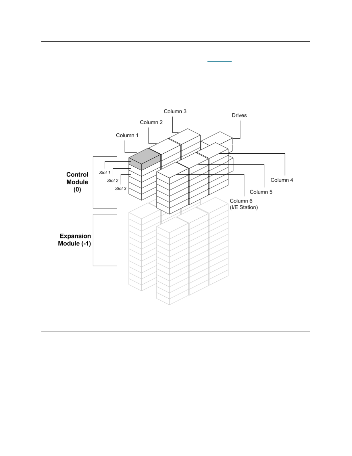
Understanding the Location Coordinates
This section describes the numbering system used to identify compon ents of the library. The library location
coordinates contain the following digits: [Module],[Column],[Slot]. Figure 10
control module and an expansion module is numbered.
Figure 10 Library Location Coordinates
shows how a library with a
Modules
Library modules are represented by the first digit of a library coordinate. Modules are identified relative to
the control module.
The control module is numbered 0 (zero). Expansion modules stacked above the control module are
addressed with positive integer digits depending on their position above the control module. For example,
the expansion module stacked directly above the control module is number 1. The expansion module
stacked directly above module 1 is number 2, and so on.
Modules stacked below the control module are numbered with negative integer digits, also depending on
their relative position to the control module. For example, the expansion modu le stacked directly belo w the
control module is number -1. The expansion module stacked directly below module -1 is number -2, and so
on.
56 Running Your Library

Columns
A storage column is a group of slots arranged vertically in the library. Columns are represented by the
second digit of a library coordinate. Columns are identified relative to the front left of the library. The column
in the front left of the library is number 1. The colu mn numbering continues around the library in a clockwise
direction. The I/E station column is always number 6.
Slots
Fixed storage slots are represented by the third digit of the library location co ordinate. Within each column,
slots are numbered from top to bottom, starting at 1. For example, in Figure 10
coordinate of Slot 1 is 0, 1, 1.
on page 56, the full location
Tape Drives
Tape drives are addressed first by module and then by tape drive bay within the module. The drive bays
within a module are numbered from top to bottom. A one-based numbering system is used. The full addre ss
of a tape drive is in the form of [module,drive bay]; for example: [0,1], [1,3], [-1,2].
Power Supplies
Power supplies are addressed as [module,PS#], where PS# is 1 for the left power supply and 2 for the right
power supply. The PS# is also etched on the module chassis, above each power supply.
Performing Media Operations
Administrative users and users can use commands on the web client and operator panel Operations menu
to perform the following media operations:
• Import data cartridges into the library
• Export data cartridges from the library
• Move data cartridges between tape drives, I/E stations, and storage slots within a partition
• Import cleaning cartridges into the library (AutoClean is enabled)
• Export cleaning cartridges from the library (AutoClean is enabled)
• Load cartridges into tape drives
• Unload cartridges from tape drives
• Change the tape drive mode from online to offline and back as needed
In addition, administrative users can:
• Clean tape drives manually, using the Tools > Drive Mgmt > Clean Drive command on the
operator panel
The following topics provide an overview of these media operations. For step-by-step procedures, se e the
library’s online Help. To access the online Help system, click the Help icon at the top right of the web client
or operator panel user interface.
Tandberg StorageLibrary T128 User’s Guide 57

Note
The information and procedures in this User’s Guide apply specifically to the
library web client and the operator panel use r inte rf ac e, no t to the ho st
application. Performing media operations through the libr ary user interface may
affect your host application. See your host application documentation for
information.
Importing Media
Note
The Import Media operation allows you to use the I/E station to import data cartridges into the library. The
library’s scanner automatically reads the barcode on new cartridges imported into the library.
This topic focuses on using the library user interface, not the host application, to import media. Using the
library to import media may necessitate performing an inventory of the library with the host application. See
your host application documentation for more information.
Before cartridges can be used for data storage, they must be assigned to a partition. If the selected par tition
is online, it will be taken offline before the import operation is performed, and brought back online after the
operation is complete. If the library contains multiple partitions, the import operation will not affect operations
in other partitions.
Before importing cartridges, verify that all tape drives are unloaded and that all cartridges are in their
appropriate storage slot location. Doing this will avoid over-loading the library with cartridges.
If you have AutoClean enabled, you can also import cleaning cartridges into the lib rary. For information, see
Importing Cleaning Media
use the I/E station to import media. For information, see Bulkloading
You must have access to the library’s I/E Station and the operator panel to import cartridges.
The process for importing cartridges includes the following steps:
1 Go to the front of the library and insert cartridges into the I/E station.
If your library has zero I/E station slots, you cannot impo rt or export media.
See Configuring I/E Station Slots
on page 64. In addition, you can bulkload cartridges into the library rather than
on page 40.
on page 59.
2 Close the I/E station door.
The Assign IE screen appears on the operator panel. You must assign the cartridges to a partition
before the import operation can begin. The screen lists only the partitions to which you have been given
access.
3 Using the Assign IE screen, assign the cartridges to a partition.
The partition button turns red after it has been selected.
Note
4 Select Apply.
5 Now that the cartridges have been assigned to a partition, you can use the Import Media screens on
either the operator panel or the web client to impo rt the cartridges into the partition. Follow the on-screen
prompts, or see the library’s online Help for step-by-step procedures. To access the online He lp system,
click the Help icon at the top right of the web client or operator panel user interface.
58 Running Your Library
If you select the wrong partition, open the I/E station door. Move the cartridge
to a different I/E station slot and close the I/E station door. The library will
rescan the I/E station, and the Assign IE screen will appear again.

You need to provide the following information in the Import Media screens to import media:
• Partition — the partition into which you want to import the cartridges. The screen lists only the
partitions to which you have been given access. The screen includes information about the partition
mode (online or offline) and the number of empty slots in the partition. Th e number of cartridges you
can import is limited to the number of empty slots.
• Media — the cartridges that you want to import.
Note
The paths to open the appropriate screens are as follows:
• From the web client, select Operations > Media > Import.
• From the operator panel, select Operations > Import Media.
For step-by-step procedures, see the library’s online Help. To access the online Help system, click the Help
icon at the top right of the web client or operator panel user interface.
You can filter the list of media by entering all or part of a barcode in the Search
text box. Use an asterisk (*) to search with wildcards. You can also sort the list
by clicking on columns with bold headings. For example, selecting the
Location column heading sorts the list by location coordinates
Bulkloading
Bulkloading is another way to load media into the library. If zero I/E st ation slots ha ve been configured, you
will always need to bulkload cartridges into the library. If I/E station slots have been configured, you may
want to perform an initial bulkload when you first start using your library. The library will perform an inventory
after the bulkload is complete.
Before bulkoading, print out the Library Configuration report from the web client to see how the physical
slots of the library are configured. The report shows what slots are unavailable or configured as cleanin g
slots or as I/E station slots. For information on accessing the report, see Viewing the Library Config ura tion
on page 69.
CAUTION
When I/E station slots have been configured as I/E slots, the I/E station door is unlocked, an d you can open
the main access door to the library. When all I/E station slots are configured as storage, the I/E station door
is always locked. You will not be able to open the main access door to bulkload tape cartridges into the
library without first unlocking the I/E station door. If possible, bulkload the library before co nfigu ring the I/E
station slots as storage. Otherwise, unlock the I/E station door. For information on locking and unlocking the
I/E stations, see Locking and Unlocking the I/E Stations
station slots, see Configuring I/E Station Slots
To perform an initial bulkload, open the access door and ma nually insert directly into storage slots as many
cartridges as you plan to use. The cartridges will not go in all the way if they are inserted incorrectly.
Note
Tandberg StorageLibrary T128 User’s Guide 59
Place cartridges in their appropriate ly configured slot location; for example,
cleaning cartridges should not be placed in slots configured for storage.
on page 66. For information on configuring I/E
on page 40.
When you open the main access door to load tape cartridges into the library,
the library will automatically generate a Reliability, Availability, and
Serviceability (RAS) ticket, alerting you to the fact that the door was opened.
For information on resolving a RAS ticket, see About RAS Tickets
on page 153.

After the initial bulkload, you can use the Import Media screen to add cartridges without interrupting library
operations, as long as I/E station slots have been configured. For more information, see Importing Media
on page 58.
Moving Media
Once media has been imported into the library, you can use the Move Media operation to move a single
data cartridge between tape drives and slots within a partition.
Note
This topic focuses on using the library user interface, not the host application, to move media. Using the
library to move media may necessitate performing an inventory of the l ibrary with the host application. See
your host application documentation for more information.
Details on using the library to move media include:
• If the partition is online, it will be taken offline before the move is performed and brought back onli ne
after the move is complete. You will be asked to confirm that you want to take the partition offline.
• You can select only the partitions to which you have been given access.
• You can only move media within one partition at a time.
You need to provide the following information in the user interface to move media:
• Partition — lists the partitions that you have permission to access.
• Selected Media — the single cartridge that you want to move.
• Selected Destination — the location to which you want to move the cartridge.
Note
If your library has zero I/E station slots, you cannot move cartridges to and
from the I/E station. See Configuring I/E Station Slots
You can filter the list of media by entering all or part of a barcode in the Search
text box. Use an asterisk (*) to search with wildcards. You can also sort the list
by clicking on columns with bold headings. For example, selecting the
Location column heading sorts the list by location coordinates
on page 40.
The paths to open the appropriate screens are as follows:
• From the web client, select Operations > Media > Move.
• From the operator panel, select Operations > Move Media.
For step-by-step procedures, see the library’s online Help. To access the online Help system, click the Help
icon at the top right of the web client or operator panel user interface.
Exporting Media
Note
The Export Media operation enables you to export data cartridges from storage slots to empty I/E station
slots for removal from the library.
60 Running Your Library
If your library has zero I/E station slots, you cannot impo rt or export media.
See Configuring I/E Station Slots
on page 40.

This topic focuses on using the library user interface, not the host application, to export media. Using the
library to export media may necessitate performing an inventory of the library with the host ap plication. Also,
if the host application has issued a prevent media removal command, you will not be able to use the library
user interface to export media. See your host application documentation for more information.
If you have AutoClean enabled, you can also export cleaning cartridges. For information, see Exporting
Cleaning Media on page 65.
Details on exporting cartridges include:
• If the partition is online, it will be taken offline before the export operation is performed and brought
back online after the operation is complete. You will be asked to confirm that you want to take the
partition offline.
• You can select only the partitions to which you have been given access.
• You can only export cartridges if empty I/E station slots are available.
• You must have access to the library’s I/E Station and the operator panel to import cleaning
cartridges.
You need to provide the following information in the Export Media screens to export media:
• Partition — the partition from which you want to export cartridges. The screens inclu de information
about the partition mode (online or offline) and the number of empty I/E station slots. The number
of cartridges you can export is limited to the number of empty slots.
• Media — the tape cartridges that you want to export.
Note
The paths to open the appropriate screens are as follows:
• From the web client, select Operations > Media > Export.
• From the operator panel, select Operations > Export Media.
For step-by-step procedures, see the library’s online Help. To access the online Help system, click the Help
icon at the top right of the web client or operator panel user interface.
You can filter the list of media by entering all or part of a barcode in the Search
text box. Use an asterisk (*) to search with wildcards. You can also sort the list
by clicking on columns with bold headings. For example, selecting the
Location column heading sorts the list by location coordinates.
Loading Tape Drives
The Load Drive operation enables you to load a cartridge from a storage slot into a ta pe drive. The storage
slot and tape drive must be assigned to the same partition.
This topic focuses on using the library user interface, not the host application, to load tape drives. Using the
library to load tape drives may necessitate performing an inventory with the host application. See your host
application documentation for more information.
Details on loading tape drives include:
• If the partition is online, it will be taken offline before the load operation is performed and brought
back online after the operation is complete. You will be asked to confirm that you want to take the
partition offline.
• You can select only partitions to which you have been given access.
• Default tape drive locations are highlighted if the barcode field is empty or the field is cleared.
Tandberg StorageLibrary T128 User’s Guide 61

You need to provide the following information in the Load Drive screens to load tape cartridges into tape
drives:
• Partition — the partition containing the cartridge you want to load into a tape drive. The screens
include information about the partition mode (online or offline).
• Media — the tape cartridges that you want to move
Note
The paths to open the appropriate screens are as follows:
• From the web client, select Operations > Drives > Load.
• From the operator panel, select Operations > Load Drive.
For step-by-step procedures, see the library’s online Help. To access the online Help system, click the Help
icon at the top right of the web client or operator panel user interface.
You can filter the list of media by entering all or part of a barcode in the Search
text box. Use an asterisk (*) to search with wildcards. You can also sort the list
by clicking on columns with bold headings. For example, selecting the
Location column heading sorts the list by location coordinates.
Unloading Tape Drives
The Unload Drive operation allows you to unload a cartridge from a tape drive to a storage slot. The storage
slot and tape drive must be assigned to the same partition.
This topic focuses on using the library user interface, not the host application, to unload tape drives. Using
the library to unload tape drives may necessitate pe rforming an inventory with the host app lication. See your
host application documentation for more information.
Details about unloading tape drives include:
• Only drives with media loaded appear on the screen.
• You can select only partitions to which you have been given access.
• If the affected partition is online, it will be taken offline before the unload operation is performed, and
brought back online after it is complete.
You need to provide the following information in the Unload Drive screens to unload tape cartridges fr om
tape drives:
• Partition — the partition containing the tape drive that you want to unload. The screens include
information about the partition mode (online or offline).
• Tape drive — the tape drive that contains the cartridge that you want to unload.
Note
The paths to open the appropriate screens are as follows:
• From the web client, select Operations > Drives > Unload.
• From the operator panel, select Operations > Unload Drive.
For step-by-step procedures, see the library’s online Help. To access the online Help system, click the Help
icon at the top right of the web client or operator panel user interface.
You can sort the list of tape drives by clicking on columns with bold headings.
For example, selecting the Location column heading sorts the list by location
coordinates.
62 Running Your Library

Changing the Tape Drive Mode
You can take the tape drive online or offline. When the tap e drive mode is online, the tape drive is available
for use. When the tape drive mode is offline, the tape drive is offline to the host application and is not
available for use.
Some operations require that the tape drive be offline. You can take a drive offline rather than the entire
library or partition so as to minimize disruption of library operations.
This topic focuses on using the library user interface, not the host application, to change the tape drive
mode. Using the library to change tape drive mode may affect the host app lication. See your host application
documentation for more information.
Details on changing the tape drive mode include:
• The default tape drive mode is online.
• You can select only tape drives in partitions to which you have been given access.
•The Online/Offline buttons toggle between modes.
Note
The paths to open the appropriate screens are as follows:
• From the web client, select Operations > Drives > Change Mode.
• From the operator panel, select Operations > Drive Mode.
For step-by-step procedures, see the library’s online Help. To access the online Help system, click the Help
icon at the top right of the web client or operator panel user interface.
If you change the mode of a control path tape drive to offline, a caution dialog
appears asking you to confirm the mode change. For information on control
path tape drives, see Modifying the Control Path
on page 43.
About Cleaning Tape Drives
Library tape drives require occasional cleaning. Cleaning cartridges are used to remove accumulated
residue from each tape drive’s read/write head.
The library supports two methods for cleaning tape drives with cleaning cartridges: AutoClean and Manual.
AutoClean — Configuring one or more dedicated cleaning slots automatically enables AutoClean. Cle aning
cartridges are stored in the designated cleaning slots. When a tape drive needs cleaning, it notifies the
library, and the library automatically cleans the tape drive using a cleaning cartridge loaded in a cleaning
slot. Automatic cleaning is integrated into routine library operations. The host application requests the library
to move a tape cartridge. If the tape drive performing the operation needs cleaning, the library will perform
the move operation and then automatically clean the tape drive with a cleaning cartridge before informing
the host application that the move operation is complete.
When a cleaning cartridge has expired, a RAS ticket informs the user to export the expired tape from the
library. If more cleaning cartridges are present, the next cleaning cartridge will be used for the next cleaning
request. If no more cleaning cartridges are available, a RAS ticket will inform the user that the tape drive
needs cleaning and that a cleaning tape needs to be imported. See
Only Administrative users can configure cleaning slots, thus enabling AutoClean. When AutoClean is
enabled, the library allows you to import and export cleaning media through the I/E Station.
For information on configuring cleaning slots, see Configuring Cleaning Slots
on importing and exporting cleaning media, see Importing Cleaning Media
Cleaning Media on page 65.
Tandberg StorageLibrary T128 User’s Guide 63
on page 39. For information
on page 64 and Exporting

Note
Manual Cleaning — When a tape drive needs cleaning, it notifies the library. If the library’s AutoClean
feature is not enabled (no cleaning slots have been configured), the libra ry generates a RAS ticket informing
the user that the tape drive needs cleaning. Administrative users can clean tape drives manually, using
commands on the operator panel user interface. For more information, see Ma nually Cleaning Tape Drives
on page 66.
Cleaning slots are not visible to the host application. To choose host-based
cleaning, do not configure any cleaning slots, and configure your host
application to manage cleaning tape drives. Configuring cleaning slots on the
library may affect the host application. See your host application
documentation for information.
Enabling AutoClean
To enable AutoClean, an administrative user must configure at least one cleaning slot in the library. For
information on configuring cleaning slots, see Configuring Cleaning Slots
AutoClean, see About Cleaning Tape Drives
on page 63.
on page 39. For a description of
Importing Cleaning Media
When AutoClean is enabled (at least one cleaning slot has been configured), you can use the Import
Cleaning Media operation to import cleaning cartridges from the I/E station to designated cleaning slots. For
information on configuring cleaning slots, see Configuring Cleaning Slots
AutoClean, see About Cleaning Tape Drives
on page 63.
on page 39. For a description of
You must have access to the library’s I/E Station and the operator panel to import cleaning cartridges.
Note
The process for importing cleaning cartridges includes the following steps:
1 Go to the front of the library and insert the cartridges into the I/E station.
Note
2 Close the I/E station door.
The Assign IE screen appears on the operator panel.
3 On the Assign IE screen, select System.
The System button turns red after it is selected. Selecting System assigns the cartridge to the physical
library and not to a specific partition.
4 Select Apply.
5 You can now use the Import Cleaning Media screen on either the operator panel or the web client to
import the cleaning cartridges into the library. Follow the o n-screen prompts, or see the library’s online
Help for step-by-step procedures. To access the online Help system, click th e Help icon at the top right
of the web client or operator panel user interface.
If your library has zero I/E station slots, you cannot import or export cleaning
media. See Configuring I/E Station Slots
Do not insert cartridges into the I/E station during the restart process.
on page 40.
64 Running Your Library

You need to provide the following information in the Import Cleaning Media screens to import media:
• Media — the cleaning cartridges that you want to import.
The screen includes information about the number of empty cleaning slots in the library. The
number of cleaning cartridges you can import is limited to the number of empty cleaning slots.
Note
The paths to open the appropriate screens are as follows:
• From the web client, select Operations > Cleaning Media > Import.
• From the operator panel, select Operations > Import Cleaning Media.
You can filter the list of media by entering all or part of a barcode in the Search
text box. Use an asterisk (*) to search with wildcards. You can also sort the list
by clicking on columns with bold headings. For example, selecting the
Location column heading sorts the list by location coordinates
Exporting Cleaning Media
When AutoClean is enabled, you can use the Export Cleaning Media operation to export one or more
cleaning cartridges from dedicated cleaning slots to the I/E station for removal from the library. You may
need to export expired cleaning cartridges or free up cleaning slots for data storage.
After exporting cleaning cartridges, you can reduce the number of co nfigured cleaning slots. The extra slots
become available for use as storage slots. For information on configuring cleaning slots, see Configuring
Cleaning Slots on page 39. For a description of AutoClean, see About Cleaning Tape Drives on page 63.
Note
If your library has zero I/E station slots, you cannot import or export cleaning
media. See Configuring I/E Station Slots
on page 40.
Details on exporting cleaning cartridges include:
• You must have access to the library’s I/E Station and the operator panel to export cleaning
cartridges.
• You can only export cartridges if empty I/E station slots are available.
You need to provide the following information in the Export Cleaning Media screens to export cleaning
media:
• Media — the tape cartridges that you want to export.
The screen includes information about the number of empty I/E station slots in the library. The
number of cleaning cartridges you can export is limited to the number of empty I/E station slots.
Note
The paths to open the appropriate screens are as follows:
• From the web client, select Operations > Cleaning Media > Export.
• From the operator panel, select Operations > Export Cleaning Media.
You can filter the list of media by entering all or part of a barcode in the Search
text box. Use an asterisk (*) to search with wildcards. You can also sort the list
by clicking on columns with bold headings. For example, selecting the
Location column heading sorts the list by location coordinates
Tandberg StorageLibrary T128 User’s Guide 65

For step-by-step procedures, see the library’s online Help. To access the online Help system, click the Help
icon at the top right of the web client or operator panel user interface.
Manually Cleaning Tape Drives
The Clean Dri ve screens on the op erator panel user inte rface allow administrative users to manually clean
tape drives.
Note
The Clean Drive screens allow you to select the tape drive that you want to clean . You are then p rompted
to insert a cleaning cartridge in the topmost I/E station slot and select Apply. The library then takes the
associated partition offline, moves the cleaning cartridge from the I/E station slot to the designated tape
drive, and cleans the tape drive.
When the operation is complete, the library moves the cleaning cartridge back to the I/E station slot and
takes the partition back online.
Note
Manually cleaning tape drives can be performed only from the operator panel. The path to open the
appropriate screen is as follows:
• From the operator panel, select Tools > Drive Mgmt > Clean Drive.
Be sure to unload the tape drive before attempting to clean it. If the tape drive is
loaded with a cartridge, it will not available for this operation.
If your library has zero I/E station slots, you will not be able to manually clean
tape drives. See Configuring I/E Station Slots
on page 40.
Locking and Unlocking the I/E Stations
Each 5U control module and 9U expansion module has an I/E station door with multiple open and close
sensors. A secondary door located behind the I/E station door acts as a redundant indicator as to whether
the I/E station is opened or closed. When you are finished accessing the I/E station, make sure the station
door is fully closed.
Administrative users can use this operation to lock or u nlock the doors for all I/E stations that are configured
as I/E station slots. If all I/E station slots are configured as storage, this operation unlocks the control modu le
I/E station only.
Note
There are three reasons the I/E station door locks:
• The library imports or exports a cartridge from the I/E station door.
While the library is attempting to import or export a tape from a given I/E station slot, only the
associated I/E station door is locked in the closed position. All other I/E station doors remain
accessible. On a get from an I/E station slot, the associated I/E station door remains locked until
the media has been successfully moved to its destination. This allows the media to be returned to
the I/E station slot in the event of a put error.
66 Running Your Library
Some host applications use a command to lock and unlock I/E station doors.
This command usually cannot be overridden by the library. Use the host
application to lock or unlock I/E station doors if this occurs. Using the library
lock/unlock operation may affe ct the host application. See your host application
documentation for information.

• A user has requested that the I/E station door be locked.
• If the I/E station slots are configured as storage slots, the door is always locked.
When all I/E station slots are configured as storage slots, you can use the Locking and Unlocking
I/E station operation to unlock the I/E station in the control module. When the I/E statio n is unlocked,
you can open the main access door on the control module. This, in turn, unlocks all remaining I/E
stations in the library, allowing you to access all remaining access doors in the library.
The paths to open the appropriate screens are as follows:
• From the web client, select Operations > I/E Station Lock/Unlock.
• From the operator panel, select Operations > Lock I/E Station.
Shutting Down or Restarting the Library
Administrative users can use the System Shutdown screen to shut down or restart the library. Some
maintenance activities require that the lib r ar y be sh ut down or resta r te d.
Shutdown shuts down the library's operating system and firmware. When performing a shutdown, the
library finishes all active commands received from the host application and does not process any new
commands. It also shuts down all partitions. To finish the shutdown, press the power switch on the front of
the control module.
Always perform a shutdown before completely removing power from the library. To completely remove
power from the library, you must turn off the power switch on each power supply. Power is completely
removed from the library when the blue LED on each power supply turns off.
To turn the library back on, turn the power switch on on each power supply, press the front power switch
again, and then follow the login procedure.
CAUTION
Restart shuts down and restarts the library's operating system and firmware. When performing a restart,
the library finishes all active commands received from the host application and does not process any new
commands. The library shuts down all partitions and restarts them during the r eboot. In addition, the library
performs an inventory of cartridges, tape drives, and slots during a reboot. Restarting takes approximately
5 minutes for the 5U control module and longer for the 14U library configuration.
If the "Not Initialized" message appears on the operator panel after the restart process is complete, the
library did not properly initialize. View the All RAS Tickets screen to find the problem that is pr eventing the
library from properly initializing. See Viewing RAS Tickets
Note
The paths to open the appropriate screens are as follows:
• From the web client, Operations > System Shutdown.
If you do not perform library shutdown before you power off the
library, loss of data could occur.
on page 154.
The Restart operation should not be performed concurrently by multiple
administrative users. You can access the screen, but you cannot apply
changes while another administrative user is performing the same operation.
• From the operator panel, select Operations > Shutdown.
Tandberg StorageLibrary T128 User’s Guide 67

68 Running Your Library

Getting Information
The About screen on the operator panel gives you a quick glance at your library settings. You can view
more information about the library by accessing items under the Reports menu. The Reports menu is
available only on the web client.
Note
Users without administrative privileges can view only certain reports. See
Understanding the User Interface
privileges.
on page 21 for information about user
Viewing System Information
The System Information report contains information on the following library settings:
• Date and time — current date, time, and time zone settings
• Physical library — host name, Internet Protocol (IP) address, seria l number, and firmware vers ion
of the physical library
• Library Partitions— name, serial number, control path, status, slots, media, and tape drives
• Tape drives — location coordinates, vendor name, model, type, physical serial number (P-SN),
logical serial number (L-SN), firmware level, sled boot version, and sled application version of all
installed tape drives
The path to open the report from the web client is Reports > System Information.
Viewing the Library Configuration
The Library Configuration report is a dynamic representation of the physical locations of various library
resources, including tape drives, slots, partitions, and modules. Use the report to view information on the
following resources:
• Tape drives — including the interface (FC or SCSI), cartridge type, mode status, assigned partition,
location coordinates, barcode, element address, vendor, model, physical serial number (SN),
logical SN, World Wide Node Name (WWNN), World Wide Port Name ( WWPN), topology req uest,
speed request, topology actual, speed actual, SCSI or loop ID, firmware level, and control path
setting of each tape drive
Tandberg StorageLibrary T128 User’s Guide 69

• Slots — including the type, assigned partition (storage and import/export [I/E] station slots only),
location coordinates, barcode (storage and I/E station slots only), cartridge type, cleaning status
(cleaning slot only), and element address of each slot
• Partitions — including the name, mode status, emulation type, barcode policy, total tape drives,
active tape drives, total cartridges, mounted cartridges, total slots, full slots, total I/E stations, full I/E
stations, and AutoClean setting of each partition
• Modules — including the manufacturer, model number, and serial number of each module
The path to open the report from the web client is Reports > Library Configuration.
Viewing Network Settings
The Network Settings report provides information on the following library settings:
• Network settings — host name, Dynamic Host Configuration Protocol (DHCP) settings, IP
address, gateway, and network mask of the library
• SSL settings — SSL, port, and cipher of the library
• SMI-S state — SMI-S state setting of the library
• SNMP settings — v1, v2, v3, algorithm, encryption, and port of the library
• SNMP-Traps — IP addresses and ports of the library
The path to open the report from the web client is Reports > Network Sett ings.
Viewing Logged in Users
The User Login report contains information about the users that are curre n tly log ged into th e libr ar y. Th e
report contains the following information:
• User name — name of logged-in user
• Role name — privilege level of logged-in user (Admin for administrative user, User for
non-administrative, non-service user)
• Login date and time — date and time the user logged into the library
• Last activity date and time — date and time the user last logged into the library
• Login location — IP address or host name of the system being used to access the system
• Management interface — user interface being used to access the system (Web for web client,
Local for operator panel)
The path to open the report from the web client is Reports > Logged in Users.
Viewing Slot Information
The All Slots report contains information on all slots that are currently assigned to a partition and all I/E
slots. The report contains the following information about each slot:
• Slot type — I/E station slot, cleaning slot, or storage slot
• Barcode — number of the cartridge installed in the slot (no barcode means the slot is empty)
• Partition — partition that owns the slot
70 Getting Information

• Location — location coordinates of the slot
• Element Address — element address of the slot
The path to open the report from the web client is Reports > All Slots.
Viewing Information About the Tandberg StorageLibrary T128
The About screen gives you a quick glance at your libra ry settings. The scr een contains informatio n about
your library, including the following information viewable from the operator panel and the web client.
From the web client, you can view the About Tandberg StorageLibrary T128report, which provides the
following information about the library:
• Serial Number
• Firmware Version Number
From the operator panel, you can navigate to the About screen, which provides the following information
about the library:
• Library Name
• Serial Number
• Firmware Version Number
• Current Date
• Current Time
From the About screen, you can also navigate to other screens for information about the tape drives and
partitions.
The paths to open the appropriate screens are as follows:
• From the web client, select Reports > About Tandberg StorageLibrary T128.
• From the operator panel, select Tools > About Library.
Tandberg StorageLibrary T128 User’s Guide 71

72 Getting Information
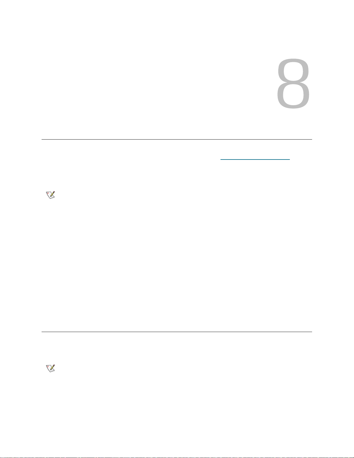
Updating Library and Tape Drive Firmware
There may be times when you will need to update your library’s firmware as directed by technical support.
You can also regularly monitor the Tandberg Data Support website at http://www.tandberg.com
firmware updates, but you need to make sure that the firmware you download is compatible with your library
and tape drives.
for
Note
There are two types of firmware that can be updated on the library: library firmware (including drive sled
firmware) and tape drive firmware. You can download library and tape drive firmware updates from the
Tandberg Data Support website.
You can also use the web client interface to update one or more tape drives in your library with an image
file downloaded from the Tandberg Data Support website. Note that updating tap e drive firmware using an
image file is a lengthy process, taking up to 90 minutes for each tape drive.
In addition, you can create a Firmware Update (FUP) tape of a tape drive firmware version alr eady installed
in your library. A FUP tape contains a specific version of tape drive firmware. You can use the tape to
transfer firmware to one or more tape drives installed in the library.
This chapter explains how to use th e Updat e Library Firmwa re and Drive Operat ions commands on the
Tools menu to update firmware.
Check the information provided on the Tandberg Data Support website at
www.tandberg.com to verify that you are selecting the correct firmwa re version
to download.
Updating Library Firmware
Using the Update Library Firmware command on th e web clien t in te r fac e, you ca n install new library
firmware.
Note
Tandberg StorageLibrary T128 User’s Guide 73
This operation should not be performed concurrently by multiple administrative
users. Y ou can access the screen, but you cannot apply chan ges while anoth er
administrative user is performing the sa me op er at ion .

Saving the current library configuration before you upd ate library firmware is recommended. If, in the future,
you need to downgrade to a previous version of the library firmware, you will lose your configured settings,
except for the date and time, license key, and network settings. You can either restore the other configurable
items using a configuration file that was saved when the earlier version o f library firmware was installed on
the library, or you can reconfigure your library’s settings. For more information, see About Saving and
Restoring the Configuration on page 155.
It is also a good idea to capture a snapshot of current logged information before making any significant
change to your system such as upgrading library firmware. Service personnel can, if necessary, use the
snapshot file to troubleshoot the library. For more information, see Capturing Snapshots of Library
Information on page 155.
Update the library firmware using the following steps:
1 Before downloading firmware, save the library configuration and capture a library snapshot. For more
information on these two operations, see Troubleshooting
on page 153.
2 Download the library firmware.
Access the Tandberg Data Support website at http://www.tandberg.com
and download the firmware
file to your personal computer.
a. On the Tandberg Data Support website, navigate to your product’s firmware.
b. Select the appropriate firmware version and download the file to your computer hard drive.
3 From the web client, select Tools > Update Library Firmware.
4 Click Browse.
5 Locate the firmware file that you have downloaded and click Open.
6 Select Apply.
A dialog box appears informing you that the library will reboot to update the library firmware.
7 Click OK to continue with the library firmware update operation.
After you download the library firmware, the update program puts the firmware package in a
predetermined location in the file structure. During the firmware update process, the variou s parts of the
firmware package are distributed to the prop er library compone nts. The updated firmwa re components
are also tracked.
After the up date process starts, you must wait until it completes. Do
CAUTION
not attempt to interrupt the process in any way. Loss of data or library
operability could occur.
Note
If a Failure message appears, the operation did not complete successfully.
The old library firmware will be reloaded. Follow instructions listed on the
screen to resolve any issues that occurred during the operation.
8 After the library has rebooted, log in to the library and open the About Library report to verify that the
library firmware was updated.
The paths to open the appropriate screens are:
• From the web client, select Reports > About Tandberg StorageLibrary T128.
• From the operator panel, select Tools > About Library.
74 Updating Library and Tape Drive Firmware

Note
9 Save the library configuration again. For information on saving the library configuration, see About
Saving and Restoring the Configuration on page 155.
If the library is still in the process of restarting, the Web browser may display an
error page or message when you try to access or log into the web client. If the
restart process fails, the library will retry every ten minutes until the library
successfully restarts.
About Tape Drive Operations
You can perform the following tape drive operations:
• Create a FUP tape — A FUP tape can be created of a tape drive firmware version already in use in
your library.
• Erase a FUP tape — When a FUP tape is no long er needed, you can erase it and reuse it as a data
cartridge or again as a FUP tape.
• Update tape drive firmware:
• Using a FUP tape
• Using a firmware image file
• Retrieve tape drive logs — Tape drive logs can be retrieved from any tape drive installed in the
library.
The following topics provide information on these procedures. For more detailed, step-by-step instructions,
see your library's online Help. To access the online Help system, click the Help icon at the top right of the
web client or operator panel user interface.
CAUTION
If your library has zero import/export (I/E) stat ion slot s, you will not be
able to perform any drive management functions. See Configuring I/E
Station Slots on page 40.
Creating a FUP Tape
A FUP tape is a tape cartridge that is used to tran sfer updated tape drive firmware code to the library. Wh en
you create a FUP tape, you save a copy of a tape drive firmware version already in use in your library. The
drive code image is copied onto the FUP tape, which you can then use to update the drive firmware on all
of the specified drives within the library. Drive code versions are independent of the library versions.
The entire process of creating a FUP tape can be performed using the operator panel. If you choose to
create the tape using the web client, be aware that part of the process must be performed on the operator
panel and that you will need access to the physical library.
Details about creating FUP tapes include:
•FUP tapes are created using a blank, or scratch, tape.
•FUP tapes can be reused.
• You cannot use a SCSI FUP tape to update tape drive firmware on a FC tape drive an d vice-versa.
• You cannot use an LTO-1 tape in LTO-3 tape drives to create FUP tapes.
• If the affected partition is online, it will be taken offline before the firmware update operation is
performed, and brought back online after it is completed. You will be asked to confirm that you want
to take the partition offline.
Tandberg StorageLibrary T128 User’s Guide 75

• You can select only empty tape drives to perform this operation. If the tape drive you want to use
contains a tape cartridge, you will need to unload it first.
CAUTION
Create a FUP tape using the following steps:
1 If you are using the operator panel, select Tools > Drive Mgmt. If you are using the web client, select
Tools > Drive Operations.
A screen listing drive management operations appears.
2 Select the option to create a firmware tape from a specific drive.
3 On the subsequent screens, perform the following actions:
a. If the librar y contain s mor e than on e drive in terf ace type (SCSI or FC), select the type of dr ive
to use to create the FUP tape.
b. Select the tape drive you want to use to create the FUP tape. You can select only empty tape
drives for this operation. If the tape drive you want to use contains a tape cartridge, you will
need to unload it first.
Note
4 Go to the front of the library and insert the scratch tape into the topmost I/E station slot. If a cartridge is
already inserted in the topmost I/E station slot, remove it.
Any data on the scratch tape will be overwritten when you create the
FUP tape.
Bold column headings in the table can be sorted. For example, selecting the
Location column heading will sort by location coordinates.
Note
5 Wait for the Assign I/E screen to appear on the local operator panel. The screen lists one or more
partitions and the System button.
6 On the Assign I/E screen, select System.
The System button turns red after it is selected. Selecting System assigns the cartridge to the physical
library and not to a specific partition.
7 If you are using the operator panel to complete the process, proceed to step 8.
If you are using the web client to complete the process, select View I/E Stations to verify that the
scratch tape is in the top slot of the I/E station. (Selecting View I/E Stations opens the Library
Configuration Report. See Viewing the Library Configuration
report.)
8 Select Apply.
Note
Be sure to place the scratch tape into the topmost I/E station slot. If you do not
place the scratch tape into the topmost I/E station slot, the FUP tape creation
operation will fail.
on page 69 for more information on this
Do not attempt to open the I/E station door during this operation. If you open
the I/E station, the FUP tape creation operation will fail.
76 Updating Library and Tape Drive Firmware

9 The FUP tape creation process takes approximately three minutes. A message notifies you when the
operation is complete. The library returns the FUP tape to the topmost I/E station slot. Remove the FUP
tape from the I/E station.
Note
You can now use the newly created FUP tape to update the drive firmware on specified drives within the
library. See Using a FUP Tape to Update Tape Drive Firmware
For more detailed, step-by-step instructions, see your library's online Help. To access the online Help
system, click the Help icon at the top right of the web client or operator panel user interface.
If a Failure message appears, the operation did not complete successfully.
Follow instructions listed on the screen to resolve any issues that occurred
during the operation.
.
Erasing a FUP Tape
When the tape drive firmware version on a FUP tape is no longer needed, it can be erased and reused as
a data cartridge or as a FUP tape.
The entire process of erasing a FUP tape can be performed using the opera tor panel. If you choose to create
the tape using the web client, be aware that part of the process must be performed on the operator panel
and that you will need access to the physical library.
If the affected partition is online, it will be taken offline before the firmware update operation is performed,
and brought back online after it is completed. You will be asked to confirm that you want to take the partition
offline.
You can select only empty tape drives to perform this operation. If the tape drive you want to use cont ains
a tape cartridge, you will need to unload it first.
Erase a FUP tape using the following steps:
1 If you are using the operator panel, select Tools > Drive Mgmt. If you are using the web client, select
Tools > Drive Operations.
A screen listing drive management operations appears.
2 Select the option to erase a firmware tape.
3 On the subsequent screens, perform the following actions:
a. If the librar y contain s mor e than on e drive in terf ace type (SCSI or FC), select the type of dr ive
to use to erase the tape.
b. Select the tape drive that you want to use to erase the tape. You can select only empty tape
drives for this operation. If the tape drive you want to use contains a tape cartridge, you will
need to unload it first.
Note
4 Go to the front of the library and insert the FUP tape you want to erase in the topmost I/E station slot. If
a cartridge is already inserted in the topmost I/E station slot, remove it.
5 Wait for the Assign I/E screen to appear on the local operator panel. The screen lists one or more
partitions and the System button.
Bold column headings in the table can be sorted. For example, selecting the
Location column heading will sort by location coordinates.
6 On the Assign I/E screen, select System.
7 If you are using the operator panel to complete the process, proceed to step 8.
Tandberg StorageLibrary T128 User’s Guide 77

If you are using the web client to complete the process, select View I/E Stations to verify that the
scratch tape is in the top slot of the I/E station. (Selecting View I/E Stations opens the Library
Configuration Report. See Viewing the Library Configuration
report.)
8 Select Apply.
on page 69 for more information on this
Note
A message notifies you when the operation is complete. The library returns the FUP tape to the topmost
I/E station slot.
9 Remove the FUP tape from the I/E station.
Note
The paths to open the appropriate screens are as follows:
• From the web client, select Tools > Drive Operations.
• From the operator panel, select Tools > Drive Management.
For more detailed, step-by-step instructions, see your library's online Help. To access the online Help
system, click the Help icon at the top right of the web client or operator panel user interface.
Do not attempt to open the I/E station door during this operation. If you open
the I/E station, the FUP tape erasure operation will fail.
If a Failure message appears, the operation did not complete successfully.
Follow instructions listed on the screen to resolve any issues that occurred
during the operation.
Using a FUP Tape to Update Tape Drive Firmware
You can update tape drive firmware using a FUP tape. A FUP tape contains a specific version of tape drive
firmware and is used to transfer the firmware to one or more tape drives within the library. Update firmware
on all of the drives in the library at the same time to make sure that all of the drives are at the same firmware
level. Having different levels of drive firmware in the library is not recommended.
The Tandberg Data Support website at www.tandberg.com provides informatio n that can help you to verify
that the library is running the appropriate level of tape drive firmware, compatible with the tape drive type.
You cannot use a SCSI FUP tape to update tape drive firmware on a FC tape drive and vice versa. Each
tape drive interface type requires unique firmware. See Creating a FUP Tape
information on FUP tapes and how to create them.
If the affected partition is online, it will be taken offline before the firmware update operation is performed,
and brought back online after it is completed. You will be asked to confirm that you want to take the partition
offline.
The entire process of updating tape drive firmware with a FUP tape can be performed using the operator
panel. If you choose to perform the operation using the web client, be aware that part of the process must
be performed on the operator panel and that you will need access to the physical library.
CAUTION
78 Updating Library and Tape Drive Firmware
Before you update tape drive firmware, make sure that cartridges are
not loaded in any tape drives. If cartridges are loaded in tape drives
during the update process, the library loses knowledge of the
cartridges' storage slot location, resulting in library and host
application inventory issues.
on page 75 for more

CAUTION
Do not turn off power to the library during the update process.
Turning off power to the library during the update can cause
problems with the library.
Note
Update the tape drive firmware using the following steps:
1 If you are using the operator panel, select Tools > Drive Mgmt. If you are using the web client, select
Tools > Drive Operations.
A screen listing drive management operations appears.
2 Select the option to update drive firmware using a firmware tape.
3 On the subsequent screens, perform the following actions:
a. If the library contains more than one tape drive interface type (SCSI or FC), select the type of
b. Select the tape drive or drives that you want to update.
Note
4 Go to the front of the library and insert the FUP tape in the topmost I/E station slot. If a cartridge is
already in the topmost I/E station slot, remove it.
This operation should not be performed concurrently by multiple administrative
users. You can access the appropriate screens, but you cannot apply changes
while another administrative user is perf or min g the sa me op er at ion .
drive to update.
Bold column headings in the table can be sorted. For example, selecting the
Location column heading will sort by location coordinates.
5 Wait for the Assign I/E screen to appear on the local operator panel. The screen lists one or more
partitions and the System button.
6 On the Assign I/E screen, select System.
The System button turns red after it is selected. Selecting System assigns the cartridge to the physical
library and not to a specific partition.
7 If you are using the operator panel to complete the process, proceed to step 8.
If you are using the web client to complete the process, select View I/E Stations to verify that the
scratch tape is in the top slot of the station. (Selecting View I/E Stations opens the Library
Configuration Report. See Viewing the Library Configuration
report.)
8 Select Apply.
The tape drive firmware update takes approximately three minutes. The library moves the newly created
FUP tape into each of the specified drives to be updated. The library updates the firmware on each
targeted drive.
A Success message notifies you when the update operation has completed successfully, and the
library returns the FUP tape to the top I/E station slot.
Note
If a Failure message appears, the tape drive firmware did not complete
successfully. Follow instructions listed on the screen to resolve any issues that
occurred during the operation.
on page 69 for more information on this
Tandberg StorageLibrary T128 User’s Guide 79

9 When the firmware update is complete, remove the FUP tape from the I/E station.
10 Open the Drive Info report to verify that the drive firmware was updated. The paths to open the
appropriate screens to view the Drive Info report are as follows:
• From the web client, select Tools > Identify Drives.
• From the operator panel, select Tools > About Library > View Drive Info.
11 Save the library configuration. For information on saving th e library configuration, see About Saving and
Restoring the Configuration on page 155.
For more detailed, step-by-step instructions, see your library's online Help. To access the online Help
system, click the Help icon at the top right of the web client or operator panel user interface.
Using an Image File to Update Tape Drive Firmware
The web client allows you to update tape drive firmware using a firmwar e image file. Note that updating tape
drive firmware using an image file is a lengthy process, taking up to 90 minutes for each tape drive.
Tape drive firmware is available at the Tandberg Data Support website at www.tandberg.com. You can
navigate to your product’s firmware from the ho m e page . Sele ct the appropriate firmware version and
download the file to your computer hard drive. The Tandberg Data Support website provides information
that can help you to verify that the library is running the appropriate level of tape drive firmware, compatible
with the tape drive type.
Note that you cannot use a SCSI firmware image to up date t ape drive firmware on a FC tape drive a nd vice
versa. Each tape drive interface type requires unique firmware.
The library allows you to update firmware on multiple tape drives at one time. Update firmware on all tape
drives of the same interface type at the same time to make sure that all drives are at the same firmware
level. Having different levels of drive firmware in the library is not recommended.
If the affected partition is online, it will be taken offline before the firmware update operation is performed,
and brought back online after it is completed. You will be asked to confirm that you want to take the partition
offline.
CAUTION
CAUTION
Note
Update tape drive firmware using the following steps:
Before you update tape drive firmware, make sure that cartridges are
not loaded in any tape drives. If cartridges are loaded in tape drives
during the update process, the library loses knowledge of the
cartridges' storage slot location, resulting in library and host
application inventory issues.
Do not turn off power to the library during the update process.
Turning off power to the library during the update can cause
problems with the library.
This operation should not be performed concurrently by multiple administrative
users. You can access the appropriate screens, but you cannot apply changes
while another administrative user is perf or min g the sa me op er at ion .
1 On the web client, select Tools > Drive Operations.
A screen listing drive management operations appears.
2 Select the option to update drive firmware using an image file.
80 Updating Library and Tape Drive Firmware

3 On the subsequent screens, perform the following actions:
a. If the library contains more than one tape drive interface type (SCSI or FC), select the type of
drive to update.
b. Select the tape drive or drives that you want to update.
Note
4 Click Browse.
5 Locate the library firmware image file and click Open.
6 Click Apply.
A Success message notifies you when the update operation has completed successfully.
Note
7 Open the Drive Info report to verify that the drive firmware was updated. The paths to open the
appropriate screens to view the Drive Info report are as follows:
• From the web client, select Tools > Identify Drives.
• From the operator panel, select Tools > About Library > View Drive Info.
8 Save the library configuration. For information on saving the library configuration, see About Saving and
Restoring the Configuration on page 155.
For more detailed, step-by-step instructions, see your library's online Help. To access the online Help
system, click the Help icon at the top right of the web client or operator panel user interface.
Bold column headings in the table can be sorted. For example, selecting the
Location column heading will sort by location coordinates.
If a Failure message appears, the tape drive firmware did not complete
successfully. Follow instructions listed on the screen to resolve any issues that
occurred during the operation.
Order a New FUP Tape From Technical Support
You can also request a new FUP tape with updated tape drive firmware from technical suppor t. Go to
www.tandberg.com and select your region. You will be redirected to a regional Tandberg Data website
providing contact information. Submit a request for a new FUP tape. Whe n you rece ive the FUP tape , yo u
can use it to update your library’s tape drives following the instructions in Using a FUP Tape to Update Tape
Drive Firmware.
Retrieving Tape Drive Logs
Administrative users can use the web client to retrieve tape drive logs. Tape drive log information can be
used to help troubleshoot library and tape drive issues.
Since the log retrieval process can take up to 90 minutes, the partition associated with the tape drive is
automatically taken offline during the process and is brought back online when the operation is completed.
Tape drive log files adhere to the following naming convention: UDS_ID_SN.dmp, where ID identifies the
tape drive coordinate location within the library and SN identifies the tape drive serial number.
Tandberg StorageLibrary T128 User’s Guide 81

Retrieve the tape drive logs using the following steps:
1 From the web client, select Tools > Drive Operations.
A screen listing drive management operations appears.
2 Select the option to retrieve a drive log.
3 On the subsequent screens, perform the following actions:
a. If the library contains more than one tape drive interface type (SCSI or FC), select the type of
drive from which you want to retrieve logs.
b. Select the tape drive from which you want to retrieve logs.
Note
4 Click Apply.
A caution screen appears with information about taking the appropriate partition offline.
5 Click OK.
A Success message notifies you when the update operation has completed successfully.
Note
6 When you see the Success message, click OK.
A dialog box appears with information on where the log was saved in the library.
7 Click OK.
A Save as dialog box appears.
8 Use the dialog box to determine where you want to save the file and click OK.
For more detailed, step-by-step instructions, see your library's online Help. To access the online Help
system, click the Help icon at the top right of the web client or operator panel user interface.
Bold column headings in the table can be sorted. For example, selecting the
Location column heading will sort by location coordinates.
If a Failure message appears, the operation did not complete successfully.
Follow instructions listed on the screen to resolve any issues that occurred
during the operation.
82 Updating Library and Tape Drive Firmware

Installing, Removing, and Replacing
This chapter describes how to add, remove, and replace hardwar e within your library. Adding, removing, or
replacing library components may require you to power off th e e ntire lib ra ry. Ther e are a fe w comp onents,
however, that you can service without powering off the library, such as replacing tape drives. Instead, you
may only need to take a specific partition offline, or you may not need to impact the status of the library at all.
WARNING
WARNING
WARNING
ALL LIBRARIES MAY BE INSTALLED IN A RACK HAVING A MAIN
PROTECTIVE EARTHING (GROUNDING) TERMINAL, AND POWER
MUST BE SUPPLIED VIA AN INDUSTRIAL PLUG AND
SOCKET-OUTLET AND/OR AN APPLIANCE COUPLER COMPLYING
WITH IEC 60309 (OR AN EQUIVALENT NATIONAL STANDARD) AND
HAVING A PROTECTIVE EARTH (GROUND) CONDUCTOR WITH A
CROSS SECTIONAL AREA OF AT LEAST 1.5 MM
T O ENSURE PROPER AIRFLOW AND ACCESS SPACE, ALLOW 60 CM
(24 INCHES) IN THE FRONT AND BACK OF THE LIBRARY.
UNDER NO CIRCUMSTANCES SHOULD A RACK BE MOVED WHILE
LOADED WITH ONE OR MORE MODULES.
WITHOUT TAPE DRIVES, TAPE CARTRIDGES, OR POWER
SUPPLIES, A 5U CONTROL MODULE WEIGHS APPROXIMATELY 58
LBS. A 9U EXPANSION MODULE, WITHOUT TAPE DRIVES, T APE
CARTRIDGES, OR POWER SUPPLIES, EXCEEDS 65 LBS.
TO AVOID SERIOUS INJURY , AT LEAST TWO PEOPLE ARE
REQUIRED TO SAFELY LIFT THE MODULES INTO POSITION.
2
(14 AWG).
Tandberg StorageLibrary T128 User’s Guide 83

Taking the Library Online/Offline
Taking a library online makes it accessible to host applications via the Storage Area Network (SAN).
Taking a library offline makes it inaccessible to host applications via the SAN.
Taking a Library Online
1 Using the library’s operator panel or the remote web client , select Operations > Change Partit ion
Mode.
2 For each partition that you want to take online, click Online.
3 Click Apply.
Taking a Library Offline
1 Using the library’s operator panel or the remote web client , select Operations > Change Partit ion
Mode.
2 For each partition that you want to take offline, click Offline.
3 Click Apply.
Cabling the Library
Use the cabling procedure appropriate for your drive type.
Connecting Library Cables (SCSI)
WARNING
Use this procedure, along with Figure 11 and Figure 12 on page 85, if you are installing a library that
includes SCSI tape drives:
ALL LIBRARIES MAY BE INSTALLED IN A RACK HAVING A MAIN
PROTECTIVE EARTHING (GROUNDING) TERMINAL, AND POWER
MUST BE SUPPLIED VIA AN INDUSTRIAL PLUG AND
SOCKET-OUTLET AND/OR AN APPLIANCE COUPLER COMPLYING
WITH IEC 60309 (OR AN EQUIVALENT NATIONAL STANDARD) AND
HAVING A PROTECTIVE EARTH (GROUND) CONDUCTOR WITH A
CROSS SECTIONAL AREA OF AT LEAST 1.5 MM
T O ENSURE PROPER AIRFLOW AND ACCESS SPACE, ALLOW 60 CM
(24 INCHES) IN THE FRONT AND BACK OF THE LIBRARY.
2
(14 AWG).
84 Installing, Removing, and Replacing
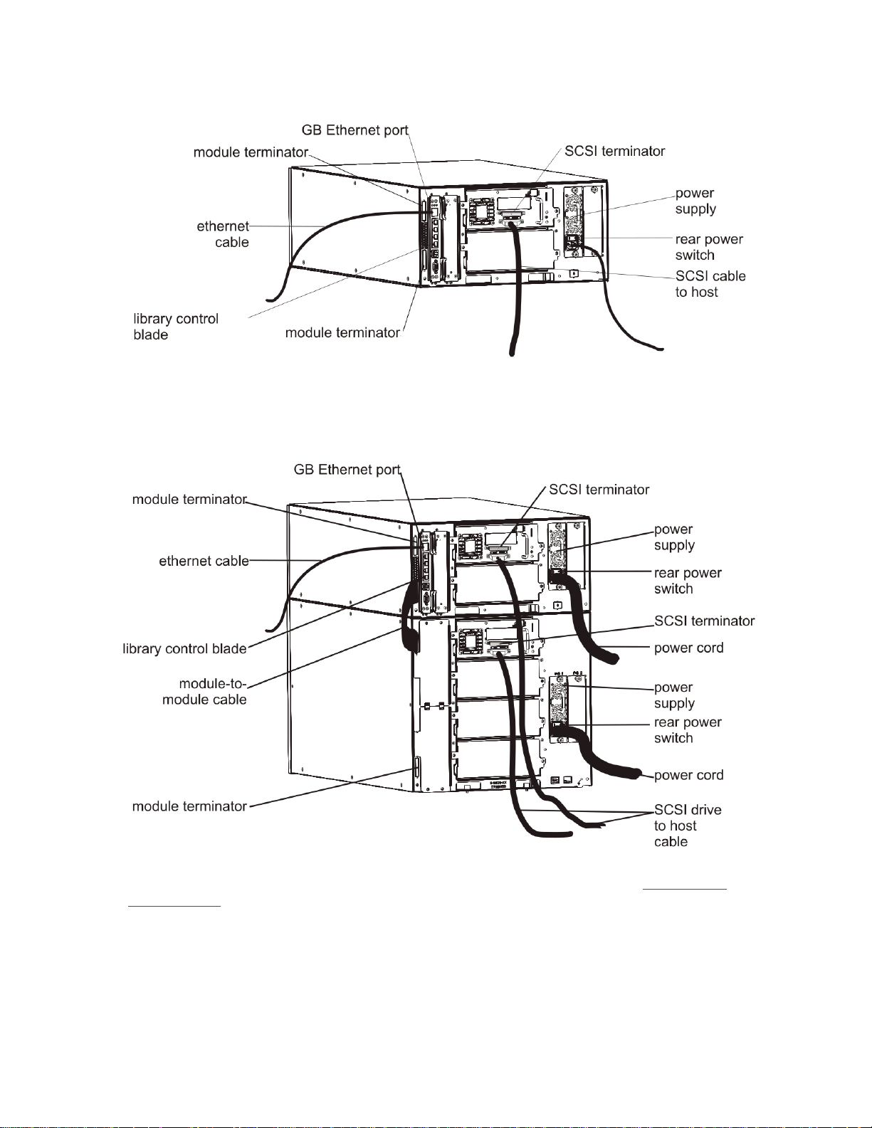
Figure 11 Stand-Alone 5U Control Module SCSI Cabling
Figure 12 Multi-Module SCSI Cabling
1 Prepare the rack to hold modules, if you want to install your library in a rack. See Installing the
Rackmount Kit on page 138 for instructions. The instructions include procedures for removing and
replacing tape drives.
2 Connect the SCSI cables to the tape drives.
a. Term inate the SCSI tape drive with an appropriate SCSI terminator.
b. Connect the SCSI tape drive to the host.
Tandberg StorageLibrary T128 User’s Guide 85

3 Connect the module-to-module cables.
The module terminator is not the same as a SCSI terminator. Using a
CAUTION
SCSI terminator instead of a module terminator will damage the
library.
a. Using the module terminators, terminate the top and bottom modules in the library stack. Install
one module terminator in the top terminator connector on the topmost module and one in the
bottom terminator connector on the bottommost module.
If your library configuration consists of a single module, place module terminators in the
module’s top and bottom module terminato r conn e cto r.
b. If you need to add a 9U expansion module to the control module, re move the module terminator
from the control module terminator connection that is closest to the 9U expansion module.
c. Replace the module terminator in the 9U expansion module in the terminator connection that is
furthest from the control module.
d. Connect the module-to-module cable from the control module to the 9U expansion module.
4 Connect your Ethernet cable to the Gigabit (GB) Ethernet port on the library control blade (LCB) for
remote access to the library via the web client.
5 Connect a power cord to the outlet on the power supply on the rear of the library.
There should always be a power cord connected to the power supply on the control module. If
redundant power supplies are used, connect a power cord to each of the additional power supply
outlets.
6 Power on the library.
a. Turn on the rear power switch of each of the power supplies.
b. Turn on the front power switch.
c. Power up the host system.
7 Verify communication with all devices on the bus.
8 Configure the library using the commands on the operator panel. See configuration information in
Configuring Your Library
on page 29.
86 Installing, Removing, and Replacing
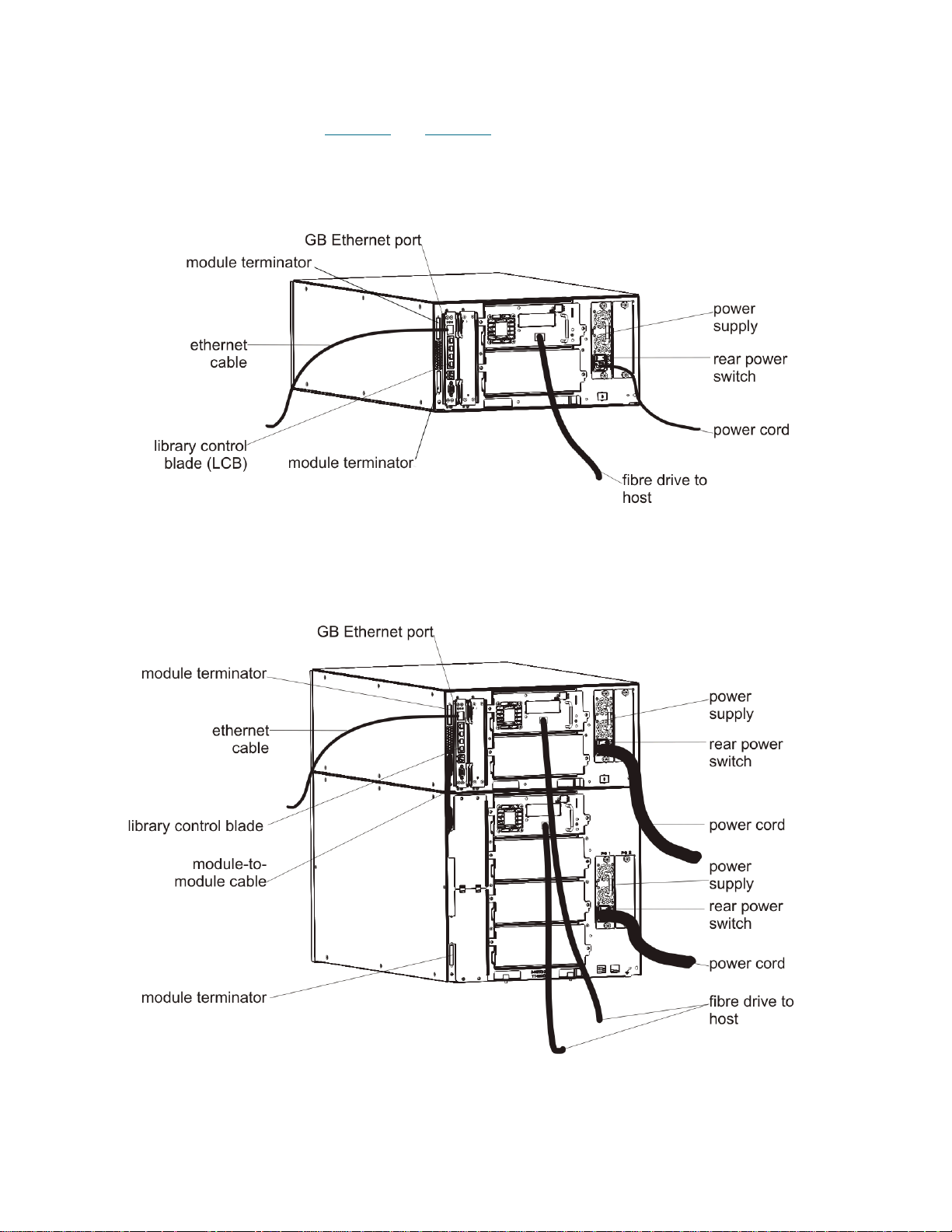
Connecting Library Cables (Fibre Channel)
Use this procedure, along with Figure 13 and Figure 14 on page 87, if you are installing a library that
includes FC tape drives:
Figure 13 Stand-Alone 5U Control Module Fibre Channel Cabling
Figure 14 Multi-Module Fibre Channel Cabling
Tandberg StorageLibrary T128 User’s Guide 87

WARNING
ALL LIBRARIES MAY BE INSTALLED IN A RACK HAVING A MAIN
PROTECTIVE EARTHING (GROUNDING) TERMINAL, AND POWER
MUST BE SUPPLIED VIA AN INDUSTRIAL PLUG AND
SOCKET-OUTLET AND/OR AN APPLIANCE COUPLER COMPLYING
WITH IEC 60309 (OR AN EQUIVALENT NATIONAL STANDARD) AND
HAVING A PROTECTIVE EARTH (GROUND) CONDUCTOR WITH A
CROSS SECTIONAL AREA OF AT LEAST 1.5 MM
2
(14 AWG).
T O ENSURE PROPER AIRFLOW AND ACCESS SPACE, ALLOW 60 CM
(24 INCHES) IN THE FRONT AND BACK OF THE LIBRARY.
Note
Pay attention to where the operator panel is positioned in the rack for optimum
usability.
1 Prepare the rack to hold modules, if you want to install your library in a rack.
See Installing the Rackmount Kit
on page 138 for instructions.The instructions include procedures for
removing and replacing tape drives.
2 Connect the fibre cables to the tape drives.
a. Attach one end of the fibre cable to the fibre port on each tape drive.
b. Attach the other end of the cable to the host or switch.
Note
The fibre cable can be connected from the tape drive to a switch rather
than a host.
3 Connect the module-to-module cables.
The module terminator is not the same as a SCSI terminator. Using a
CAUTION
SCSI terminator instead of a module terminator will damage the
library.
a. Using the module terminators, terminate the top and bottom modules in the library stack. Install
one module terminator in the top terminator connector on the topmost module and one in the
bottom terminator connector on the bottommost module.
If your library configuration consists of a single module, place module terminators in the
module’s top and bottom module terminator connectors.
b. If you need to add a 9U expansion module to the control module, remove the module terminator
from the control module terminator connection that is closest to the 9U expansion module.
c. Replace the module terminator in the 9U expansion module terminator connection furthest from
the control module.
d. Connect the module-to-module cable from the control module to the 9U expansion module.
4 Connect your Ethernet cable to the Gigabit (GB) Ethernet port on the Library Control Blade (LCB) for
remote access to the library via the web client.
5 Connect a power cord to the outlet on the power supply on the rear of the library.
There should always be a power cord connected to the power supply on the control module. If
redundant power supplies are used, connect a power cord to each of the additional power supply
outlets.
6 Power on the library.
88 Installing, Removing, and Replacing
 Loading...