


EN | FR | DE | ES | IT | NL | FI | SV
USER’S GUIDE


USER'S GUIDE |
EN |
|
|
CUSTOMER SERVICE CONTACTS |
|
Suunto Oy |
Phone +358 9 875870 |
||
|
Fax +358 9 87587301 |
||
Suunto USA |
Phone 1 |
(800) |
543-9124 |
Canada |
Phone 1 |
(800) |
776-7770 |
European Call Center |
Phone +358 2 284 11 60 |
||
Suunto Website |
www.suunto.com |
||
1
TABLE OF CONTENTS |
|
|
CHAPTER 1 INTRODUCTION .................................................................... |
5 |
|
1.1 |
General Information .......................................................................................... |
5 |
1.2 |
Care and Maintenance ...................................................................................... |
5 |
|
1.2.1. Care of the Suunto Observer .................................................................. |
5 |
1.3 |
Water Resistance ............................................................................................... |
6 |
1.4 |
Battery Replacement ......................................................................................... |
6 |
1.5 |
Adjusting the Bracelet (St and Tt models) ....................................................... |
8 |
1.6 |
Main Functions (Modes) .................................................................................... |
9 |
1.7 |
Backlight Features ............................................................................................. |
9 |
1.8 |
Button Functions ................................................................................................ |
9 |
1.9 |
LCD Display ...................................................................................................... |
10 |
1.10 Measurements and Units ................................................................................. |
11 |
|
|
1.10.1 To Set or Check Unit of Measurement Settings ............................... |
11 |
1.11 |
Pressure Sensor Calibration ............................................................................ |
12 |
CHAPTER 2 TIME MODE .......................................................................... |
13 |
|
2.1 |
Setting up the Time and Calendar ................................................................ |
13 |
2.2 |
Chronometer Sub Mode .................................................................................. |
14 |
|
2.2.1 How to Use the Chronometer ................................................................. |
14 |
|
2.2.2 To View the Chronometer Memory ....................................................... |
15 |
2.3 |
Daily Alarm Sub Mode .................................................................................... |
16 |
|
2.3.1 Setting the Daily Alarm(s) ...................................................................... |
17 |
CHAPTER 3 ALTIMETER MODE ............................................................... |
17 |
|
2
3.1 |
Altimeter-Barometer Use ................................................................................. |
18 |
|
3.2 |
Setting the Altimeter ........................................................................................ |
19 |
|
3.3 |
Logbook Sub Mode ......................................................................................... |
21 |
|
|
3.3.1 Starting and Stopping a Logbook Recording ....................................... |
21 |
|
|
3.3.2 To View in the Logbook Mode .............................................................. |
21 |
|
3.4 |
Fast Cumulative Feature ................................................................................. |
23 |
|
3.5 |
Logbook History Sub Mode ............................................................................. |
23 |
|
|
3.5.1 Clearing the Logbook History ................................................................. |
24 |
|
3.6 |
Effect of Air Temperature on Altitude Measurement ..................................... |
25 |
|
CHAPTER 4 |
BAROMETER MODE ............................................................. |
28 |
|
4.1 |
Setting the Sea Level Pressure ...................................................................... |
29 |
|
4.2 |
4-Day Memory Sub Mode ............................................................................... |
30 |
|
4.3 |
Barometric Trend Indicator ............................................................................. |
31 |
|
CHAPTER 5 |
COMPASS MODE .................................................................. |
31 |
|
5.1 |
Bearing Tracking Sub Mode ........................................................................... |
32 |
|
5.2 |
Declination Adjustment Sub Mode ................................................................. |
33 |
|
|
5.2.1 Setting the Local Declination ............................................................... |
33 |
|
5.3 |
Calibrating the Compass ................................................................................. |
34 |
|
CHAPTER 6 |
FREQUENTLY ASKED QUESTIONS .................................... |
35 |
|
CHAPTER 7 |
ABBREVIATIONS ............................................................... |
38 |
|
CHAPTER 8 COPYRIGHT AND TRADEMARK NOTICE ........................... |
39 |
||
CHAPTER 9 |
CE COMPLIANCE ............................................................... |
39 |
|
CHAPTER 10 LIMITS OF LIABILITY AND ISO 9001 COMPLIANCE ......... |
40 |
||
CHAPTER 11 DISPOSAL OF THE DEVICE ................................................ |
40 |
||
3
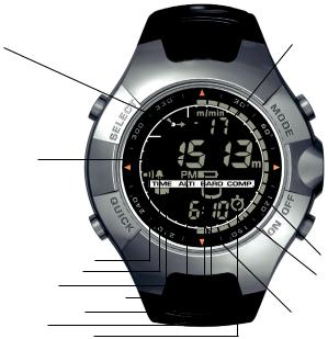
Figure 1.1
f)
SELECT
b)
QUICK
-Altitude Alarm Indicator
-Daily Alarm Indicator
-Mode Indicator
-AM/PM Indicator (12h display)
-Low Battery Indicator
-Use Indicator
-Chronometer Indicator
a)
MODE
PRESSURE
SENSOR
ON / OFF
d)
e )
c)
4
CHAPTER 1 INTRODUCTION
1.1 GENERAL INFORMATION
The Observer Wristop Computer is a reliable high precision electronic instrument, intended for recreational use. The outdoor enthusiast who enjoys venturing in sports like skiing, kayaking, mountain climbing, hiking and biking can rely on the Observer’s accuracy.
NOTE: The Observer should not be substituted for acquiring measurements that require professional or industrial precision and should not be used to acquire measurements when skydiving, hang gliding, paragliding, gyrocopter riding and flying small aircraft.
The Observer is available in three different material combinations:
Observer Sr with stainless steel housing and elastomer strap, Observer St with stainless steel housing and stainless steel / elastomer bracelet and Observer Tt with Titanium housing and Titanium / elastomer bracelets. All material versions have identical functions and operation.
1.2 CARE AND MAINTENANCE
1.2.1 Care of the Suunto Observer
Only perform the procedures described in this manual. Never attempt to disassemble or service your Suunto Observer. Protect your Suunto Observer from shocks, extreme heat and prolonged exposure to direct sunlight. Avoid rubbing the Suunto Observer against rough surfaces as this may scratch the face. If not in use, your Suunto Observer should be stored in a clean, dry environment at room temperature.
The Suunto Observer can be wiped clean with a lightly moistened (warm water) cloth. If there are stubborn stains or marks, you can apply mild soap to the area. Do not expose the Suunto Observer to strong chemicals such as gasoline, cleaning solvents, acetone, alcohol, insect repellents, adhesives and paint, as they will damage the unit’s seals, case and finish. Make sure the area around the sensor is kept free of dirt and sand. Never insert any objects into the sensor opening.
5
1.3 WATER RESISTANCE
Suunto Observer is tested with ISO (International Organization for standardization, www.iso.ch) standard 2281. This means that the product is water-resistant. In addition to the term ‘water resistant’, Suunto Observer is marked with an indication of a test overpressure given as a depth in meters (100 m/330 feet). This indication, however, does not correspond to a diving depth but refers to the pressure at which the water overpressure test was conducted.
This means that you cannot dive to a depth of 100 m/330 ft. with your Suunto Observer. Rain, showering, swimming and other normal exposure to water will not affect its operation but the buttons shall not be pressed if exposed to water in any circumstances.
NOTE: Suunto Observer wristop computers must not be used for diving.
1.4 BATTERY REPLACEMENT
Suunto Observer operates on a 3-Volt lithium cell, type: CR 2032. The life expectancy is approximately 12 months in the Time mode.
A low-battery warning indicator is activated on the display when approximately 5–15 percent of the battery capacity is still available. When this occurs, you should replace the battery. However, extremely cold weather may activate the low battery warning indicator even though the battery is still fully operational. If the battery warning indicator is activated in temperatures above 10°C (50°F), replace the battery.
NOTE: Heavy use of the backlight, altimeter and compass will significantly reduce battery life.
You can replace the batteries yourself as long as you do it properly to avoid any leakage of water into the battery compartment or computer. Always use original battery replacement kits. (They include a new battery, battery lid and O-ring.) You can purchase the battery kits from official Suunto retailers.
NOTE: When replacing the battery, also replace the battery lid and O-ring. Never use the old ones.
6
NOTE: Change the battery at your own risk. Suunto recommends |
|
||
you to have the batteries changed in official Suunto |
! |
||
services. |
|||
|
|||
To replace the battery: |
|
||
1. |
Insert a coin into the slot located on the battery |
|
|
|
compartment cover on the backside of your Suunto |
|
|
|
Observer. |
! |
|
2. |
Turn the coin counterclockwise until it is aligned |
||
|
|||
|
with the open position marker. |
|
|
3. |
Remove the battery compartment cover and the |
! |
|
|
O-ring, and discard them. Ensure that all surfaces |
||
|
|
||
|
are clean and dry. |
|
|
4. |
Remove the old battery carefully. |
|
|
5. |
Place the new battery into the battery compart- |
! |
|
|
ment under the metal contact clips, with the posi- |
|
|
|
tive side facing up. |
|
|
6. |
With the O-ring in the correct position, replace the |
! |
|
|
battery compartment cover and turn it with the |
||
coin clockwise until it is aligned with the closed position marker. Do not press onto the battery compartment cover while turning it with a coin.
NOTE: Perform battery replacement with extreme care to ensure that your Suunto Observer remains water resistant. Careless battery replacement may void warranty.
WARNING: This Suunto product contains a Lithium cell battery. To reduce risk of fire or burns, do not disassemble, crush, puncture, short external contacts, charge or dispose
7

of in fire or water. Replace only with manufacturer specified batteries. Recycle or dispose of used batteries properly.
1.5 ADJUSTING THE BRACELET (ST AND TT MODELS)
The metal / elastomer bracelets of the Observer models St and Tt have to be adjusted for the user. The steps are
1.Remove the buckle by releasing the spring bars with pin, paper clip or other sharp object.
2.Remove both spring bars from the pin holes.
3.Shorten the bracelet by cutting along the grooves on the inner surface of the bracelet. You can do this for instance with scissors. If you are unsure of the correct length, cut the pieces one by one and test the length after cutting each piece. Cut in turns from both sides of the bracelet to keep the sides equally long. Be careful in order not to shorten the bracelet too much.
4.Replace the spring bars into the last pin holes of both sides of the bracelet.
5.Attach the buckle to the bracelet by placing the spring bars into the holes in the buckle. In both sides of the buckle are holes for two different positions. This can be used for fine ad-
!
!
!
! 
8
justing of the bracelet length. Make sure that the spring bars are positioned straight in the buckle.
1.6 MAIN FUNCTIONS (MODES)
The Observer has four main modes: TIME, ALTIMETER, BAROMETER, and COMPASS. In each of the features there are associated sub modes providing further enhancements to its usefulness during your outdoor adventures. All key features and sub features will be discussed in further detail following this chapter.
1.7 BACKLIGHT FEATURES
The Observer has an electroluminescent backlight. To activate the backlight, press and hold the [MODE] button for 2 seconds. The backlight will remain on for approximately 10 seconds. If you press buttons to operate, the backlight remains on 10 seconds from the last pressing.
1.8 BUTTON FUNCTIONS
The Observer is operated with four buttons as shown in Fig. 1.1: [MODE], [ON OFF], [QUICK], and [SELECT].
The MODE Button
Located on the top right of the Observer performs the following functions:
•A short press allows you to move from one mode to the next (TIME, ALTI, BARO, COMP).
•While in the sub mode level, a short press returns you to the main mode.
•During the setup process, a short press accepts all changes and exits the set function.
•A long press of 2 seconds activates the backlight feature.
The ON OFF Button
Located on the bottom right of the Observer performs the following functions:
•In the TIME Mode, the bottom field view can be scrolled displaying the calendar
9
date, seconds, or dual time.
•During the setup process, a short press causes the selected value to increase.
•For chronometer, a short press acts as a start/stop.
•In ALTIMETER mode the logbook starts and stops with two short presses.
•In the COMPASS mode, two short presses change between the normal compass and bearing tracking feature.
The QUICK Button
Located on the bottom left of the Observer performs the following function:
•In the setup process, pressing the [QUICK] button causes the selected value to decrease.
•In the TIME, ALTIMETER, or BAROMETRIC mode, a short press quickly displays the cumulative information of the current logbook recording. Refer to Chapter 3, Fast Cumulative Features for more information
•For chronometer, this button is used for lap times and zeroing.
•In COMPASS mode, a short press locks the bearing.
The SELECT Button
Located on the top left of the Observer performs the following functions:
•In a main mode level, a short press allows you to enter into the sub modes of the particular function or return to the main mode.
•For entering the setup process, a long press of 2 seconds allows you to initiate changes to the Observer’s functions.
•While in the setup process, a short press allows you to move between settable units or values and determine preferences.
1.9 LCD DISPLAY
Designed to offer maximum clarity and simplicity the display is divided into several areas as shown in Fig. 1.1.
10

a)The top field displays numbers or text depending on the mode or sub mode you are viewing.
b)The middle field displays large numbers and/or the related unit of measure of a function.
c)The bottom field displays either numbers and/or text.
d)The Mode Indictor Bar displays the main modes of the Observer. The half oblong
shape  located just below the bar indicates the mode you are viewing. The halfmoon shape
  under the mode indicator indicates the Observer is being used as a barometer (weather station) or altimeter.
e)The outer circumference of the LCD graphically tracks the units of measure based on
the selected mode.
f) On the top left, an arrow shaped  Barometric Trend Indicator provides a quick reference view of weather conditions.
1.10 MEASUREMENTS AND UNITS
The Observer supplies two units of measure: Metric or Imperial. Each unit can be selected individually.
Metric Unit of Measure |
Imperial Unit of Measure |
m |
ft |
m/min |
ft/min |
ºC |
ºF |
hPa |
inHg |
1.10.1 To Set or Check Unit of Measurement Settings
If the mode indicator is not on TIME, press the [MODE] button until it is directly below TIME.
1. Press the [MODE] and [SELECT] buttons simultaneously for 3 seconds to enter the
11
setup mode. The top field will display “SET” momentarily and then change to “UNI”.
NOTE: Setup mode will automatically exit if left idle for more than one minute.
2.Press the [SELECT] button for 2 seconds to view the first setting. You will see the first unit flashing.
WARNING: If you perform a short press of the [SELECT] button while in the “UNI” setting mode, you will switch to Pressure Sensor Calibration. Refer to the next section for more details.
3.Press the [SELECT] button to move to the unit you want to change. You can change the flashing unit. The units are in the following order: m/ft, m/min / ft/min, hPa/inHg, ºC/ºF.
4.Press the [ON OFF] or [QUICK] button to toggle between the metric and imperial settings.
5.To confirm the setting(s), press the [MODE] button.
6.To exit the setup process, press the [MODE] button again.
1.11 PRESSURE SENSOR CALIBRATION
WARNING: This is a FACTORY CALIBRATION SETTING. Do not enter this mode.
If you enter this mode in error, exit immesdiately by pressing the [MODE] or [SELECT] button to return to the “UNI” setting mode. Normally there is no need to alter the calibration.
If the Pressure Setting Calibration has been altered, you can return the factory setting. Proceed as follows: In the calibration setting mode, scroll the barometric pressure value up or down until text “dEF” appears. This is the factory setting. Then exit by pressing [MODE].
12
CHAPTER 2 TIME MODE
There are three time sub modes: time, chronometer and alarms.
NOTE: These functions are accessible in the TIME mode, i.e. when the mode indictor is below TIME.
In the watch time mode, the fields display the following data as shown in Fig. 2.1:
a)Day of the week;
b)Current time;
c)Date dd.mm in 24h display or mm.dd in 12h display, seconds or dual time according to the last selection (changing data with the [ON OFF] button;
d)Am/pm indicator in 12 h display; and
e)Graphical display of seconds, once every two seconds a new segment lights up until a full circle of segments (60 seconds) is lit.
2.1 SETTING THE TIME AND CALENDAR
1.In the main mode of the time function, press the [SELECT] button for 2 seconds to begin the setup process. In the bottom field, seconds will begin to flash.
2.Press the [SELECT] button to move to the field you want to change. The order of fields is seconds, minutes, hours, 12/24h, year, month, day, dual-time hours, dualtime minutes. You change the value in the field that is flashing.
3.Press the [ON OFF] button to scroll the value in the field up or the [QUICK] button to scroll down. In the seconds field, the [QUICK] button resets the seconds to zero.
4.Press the [MODE] button to accept the changes made and exit the setup process.
NOTE: If the 12-hour clock is chosen either AM/PM will appear below the hour in the middle field and the date shows the month first then the day.
Once you determine the year, month and day, the Observer will supply the day of the week in the top field.
Setup mode will automatically be released if left idle for more than one minute.
13
The dual time will stay the same, even though the time in the main time mode is adjusted. For example, if you set the dual time to show your home time, your home time will always be displayed in the sub mode even if you travel to a different time zone and adjust the time in the main time mode.
The dual time function is completely independent from the current time and does not effect the alarms or the memory functions. These are dependent on the current local time in the main time mode.
2.2 CHRONOMETER SUB MODE
In the TIME mode, press the [SELECT] button once to enter this sub mode. The Observer chronometer feature:
•Can record 1-99 split and lap times; and
•Obtain a maximum range of one run (timing event) up to 24:00:00. Upon exceeding
this range the Observer will activate an audible sound indicating the timing process has stopped.
In the chronometer mode, the fields display the following data as shown in Fig. 2.2:
a)Seconds and tenths of a second;
b)Hours and minutes;
c)Icon of a “stopwatch”; and
d)Current time.
2.2.1 How to Use the Chronometer
In the chronometer mode:
1.Press the [ON OFF] button to start the chronometer.
2.Press the [QUICK] button to store the lap time and split time into memory. Lap and split times are displayed as follows:
In the top field the lap time is shown for the latest lap. The number of this lap is shown in the bottom field “L #” (# = lap number). The lap time is displayed for five seconds before the measured split time is displayed.
14
The split time is indicated by the abbreviation “SPL” (SPL = split) in the bottom field displaying for five seconds before it returns to showing the run time.
NOTE: You can continuously press the [QUICK] button during this activity to record and display new lap and split times up to 99 times.
3.Press the [ON OFF] button to stop the chronometer.
4.Press the [QUICK] button to reset the chronometer to zero once the chronometer is stopped.
NOTE: The timing of another event cannot start until the stopwatch has been zeroed.
NOTE: Starting the timing of another event removes the data of the previous timing from the memory.
NOTE: When the timing is going on, the chronometer remains active in the background when you switch to other modes or sub modes. A stopwatch icon is displayed in the bottom field to indicate that the chronometer function is active.
2.2.2 To View the Chronometer Memory
While in the chronometer mode, press the [SELECT] button for 2 seconds. This sub mode features three main screens. You use the [ON OFF] button to advance through the screens and the [QUICK] button to scroll back to the first screen.
The first screen (Fig. 2.3) displays:
a)The year of the timed event;
b)The time the event started to record;
c)The date of the timed event;
d)The stopwatch icon; and
e)The text “MEM” to indicate the memory view.
You press the [ON OFF] button to move to the next screen.
The second screen (Fig. 2.4) displays:
15
a)The total number of laps stored in the middle field; and
b)The text “MEM and “LAP” and the stopwatch icon in the bottom field.
You press the [ON OFF] button to move to the next screen. In this mode, you can view the individual lap and split times, each displaying its information on separate screens. You can view individual sets of lap and split times by using the [ON OFF] button to advance through the screens and the [QUICK] button to scroll back to the first screen. The screens are setup in chronological order beginning with lap 1.
These screens (Figures 2.5 and 2.6) display:
a)The seconds and tenths of seconds of the lap or split time in the top field;
b)The hours and minutes of the lap or split time in the middle field; and
c)The text “MEM” and the text “L #”(L # = Lap time number #) or “SPL” (SPL = split time) in the bottom field. The stopwatch icon appears on the right side. The lap time will be viewed first and then the corresponding split time will follow automatically.
NOTE: If a display is on for an extended period of time, the lap and split times will begin to flash alternating at 4-second intervals. After10 minutes the wristop will exit this view mode automatically.
Press the [ON OFF] button to continue viewing the reminder of lap and split times recorded. When the last lap and split times have been viewed, the display will show the finishing time of the event in middle field and the text “End” (indicating the end of timing) in the bottom field.
Press the [MODE] button once to exit and return to the chronometer sub mode and a second time to return to the main time mode.
2.3 DAILY ALARM SUB MODE
The Observer allows you to select and enter settings for up to three alarms.
In the TIME mode, press the [SELECT] button twice to enter this sub mode. (After stopwatch)
16
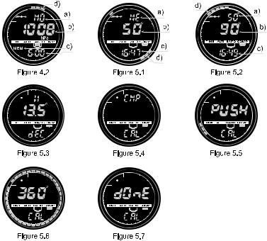
In the Daily Alarm mode (Fig. 2.7):
a)“ON” or “OFF” (the activation status of an alarm) display in the top field;
b)The alarming time displays in the middle field; and
c)The alarm (1, 2, or 3) displays in the bottom field.
Press the [ON OFF] or the [QUICK] button to toggle between the alarms 1,2, or 3 and view the settings for each alarm. If any of the alarms is activated, a bell icon displays over the mode bar.
2.3.1 Setting the Daily Alarm(s)
1.Press the [ON OFF] or the [QUICK] button to select alarm 1,2, or 3.
2.Press the [SELECT] button for 2 seconds. In the top field, the “ON” or “OFF” will begin to flash.
3.Press either the [ON OFF] or the [QUICK] button to toggle between “ON” and “OFF”.
4.At the setting desired, press the [SELECT] button to move to the next settings. They follow in order hours, minutes. The field you can change is flashing.
5.Press the [ON OFF] button to scroll the value up or the [QUICK] button to scroll down.
6.At the alarm time desired, press the [MODE] button to accept the changes and exit the setup process. An icon of a bell will appear at the bottom left side on the middle field to signify an alarm has been activated.
The Alarm setup is complete. To activate up to three alarms, please repeat steps 1-6. The alarm volume is not adjustable.
CHAPTER 3 ALTIMETER MODE
The Altimeter provides you with:
•An adjustable unit of measure either meter or feet: meter range -500 to 9000; ft range -1,600 to 29500;
•A resolution of 1m or 3ft;
•A display up-date on the rate of vertical movement in intervals of 1 second for 3
17
minutes, then every 10 seconds or less;
•A logbook, recording 99 single logs including the total ascent, total descent, number of runs, and the duration of the log.
•Altimeter-Barometer use feature
To view and use the Altimeter function:
Press the [MODE] button until the indicator is directly below ALTI.
In the ALTIMETER mode the fields display data as shown in Fig. 3.1:
a)The vertical ascent or descent rate in meters or feet per min;
b)The current altitude in increments of 1 meters or 3 feet (depending on the unit of measure selected);
c)Altimeter mode and altimeter use indicator;
d)The current time; and
e)The outer circumference of the LCD graphically displays lit segments representing the altitude over a full thousand meters or feet (one complete circle is equivalent to 1000 m or 1000 ft)
3.1 ALTIMETER-BAROMETER USE
The Observer can be used as either a weather station or altimeter. This operating feature is chosen in the setup process while in the altimeter or the barometer mode. To toggle between these icon positions, hold the [Select]-button in for 2 seconds and then, press the [Quick] or [On Off]-button to lock in one of the functions.
The icon for this function is displayed under the corresponding mode indicator (ALTI or BARO) in a half-moon  shape. The position of the icon indicates whether the Observer is being used as a weather station (BARO) or altimeter (ALTI).
NOTE: This is different than moving between ALTI and BARO main modes.
THIS IS IMPORTANT.
The use indicator has to be in ALTI position, otherwise the altitude display is fixed.
18
When Altimeter Use is selected:
•The unit will be used as an altimeter.
•All pressure changes are interpreted as altitude changes.
•The sea level pressure reading displayed in the barometer mode will not change, even though the absolute pressure reading will change.
When Barometer Use is selected:
•The unit will be used as a weather station.
•The unit interprets all pressure changes as being due to a change in the weather.
•Measured changes will affect only the pressure reading displayed in the barometer mode. Both sea level pressure and absolute pressure reading will change. These changes won’t affect the altitude reading in the altimeter mode while barometer use is activated.
The Observer leaves the factory set to be used as an altimeter.
3.2 SETTING THE ALTIMETER
In setting the Altimeter, there are two processes that can be performed:
•The Reference Altitude (known altitude at the current location); and
•The Altitude Alarm (signals you when a certain programmed altitude is reached).
IMPORTANT NOTE:
In order to set the altitude in the Altimeter mode, the altitude must be known. That information can be found by utilizing a topographical map, identifying the current location with the associated altitude marked. You can proceed and follow the instructions, setting the altimeter, provided in the section below.
If the Altitude is not known, you can set the sea level pressure in the Barometric mode. Refer to Chapter 4, Setting the Sea Level Pressure.
Setting the Sea Level Pressure will adjust the altimeter to the current altitude within approximately ten meters or 30 ft.
19
For information regarding the effect of air temperature on altitude measurement refer to the last section of Chapter 3.
Information on the current sea level pressure can be obtained through newspapers, local news and radio weather reports, the local airport facility or through the Internet under local weather.
To set the altimeter:
1.In the altimeter main mode (mode indicator below ALTI), Press the [SELECT] button for 2 seconds. In the top field, the text “RE” (indicating reference altitude) displays. In the middle field, the current altitude displays. In the bottom field the half-moon shaped use indicator under the indicator bar will begin to flash (Altimeter-Barometer use feature) and the text “USE” will appear.
2.Press either the [ON OFF] or [QUICK] button to toggle the icon to the position under “ALTI” (for altimeter use) or “BARO” (for barometer use).
3.At the desired preference, press the [SELECT] button to move to the next setting. In the middle field, the reference altitude value will begin to flash.
4.Press either the [ON OFF] button to scroll the value up or the [QUICK] button to scroll down.
5.At the desired reference altitude, press the [SELECT] button to move to the next setting (Altitude Alarm setting). In the top field, the “ON” or “OFF” will begin to flash.
6.Press either the [ON OFF] or the [QUICK] button to toggle between the “ON” and “OFF” for the Altitude Alarm.
NOTE: An activated altitude alarm is indicated with an alarm symbol.
7.At the desired setting, press the [SELECT] button to move to the next setting. In the middle field, the alarm altitude will begin to flash.
8.Press either the [ON OFF] button to scroll the value up or the [QUICK] button to scroll down.
20
9.At the desired altitude, press the [SELECT] button to view the setup preferences for confirmation or for additional changes, or press the [MODE] button to accept the changes and exit.
NOTE: You can return to main ALTI display by pressing [MODE] during any of the steps 1-9.
Once you have set the reference altitude of the current location to the known altitude, the Observer will also correct the sea level pressure, and therefore, it will not be necessary for this function to be set.
NOTE: Setup mode will automatically be released if left idle for more than one minute.
3.3 LOGBOOK SUB MODE
3.3.1 Starting and Stopping a Logbook Recording
In the main altimeter mode, a logbook recording starts by performing two short presses of the [ON OFF] button. An ongoing recording is indicated with flashing “LOG” text in the bottom field. To stop a logbook recording, you must be in the altimeter mode and perform two short presses of the [ON OFF] button again.
The memory capacity is 99 logs, each at maximum 20 hour duration. After recording the 99th logbook, the Observer writes the next logbook over the logbook number 1 (the oldest log) and then continues in numeric order.
The logbook is recording in 10-second intervals, which is quick enough for all activities. It is not possible to view the individual values of the logbook.
NOTE: You can be in other modes while recording. To indicate logbook-recording activity, the Observer will display the text “LOG” flashing in the bottom field.
3.3.2 To View in the Logbook Mode
In the Altimeter mode, press the [SELECT] button once to enter this sub mode. The logbook mode features five screens. The first screen displays for 7 seconds. Thereafter,
21
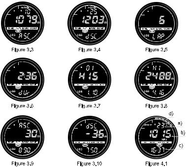
the screens will increment (2-5) displaying at four-second intervals. 1. The first screen (Fig. 3.2):
•The top field displays the year;
•The middle field displays the text “LO” (LO = logbook) with the current logbook number flashing; and
•The bottom field displays, the month and day of which the particular logbook was
recorded. To the left of the date, is the text “Log”.
To view previous logs captured, press the [QUICK] button to scroll down.
2.The second screen (Fig. 3.3) shows the ascent information for the particular logbook that is being viewed.
•The top field displays the average ascent rate during the event.
•The middle field displays the total vertical ascent.
•The bottom field displays the text “ASC” along with the text “Log” to the left.
NOTES: The maximum asc/dsc that can be shown in one logbook is 39,999 m / ft. After this number the counter starts again at zero.
3.The third screen (Fig. 3.4) shows the descent information for the particular logbook that is being viewed.
•The top field, the average descent rate during the event.
•The middle field, the total vertical descent.
•The bottom field, the text “dSC” along with the text “Log” to the left.
4.The fourth screen (Fig. 3.5) shows the number of laps (runs) completed for the particular logbook that is being viewed.
•The middle field, the total number of ascents or descents.
•The bottom field, the text “LAP” along with the text “Log” to the left.
NOTE: A lap is a vertical movement including both ascent and descent equaling 50 meters (150 ft) or above. The first lap can be also only descent.
5. The fifth screen (Fig. 3.6) shows the time duration of recording information in the
22
particular logbook that is being viewed.
•The middle field, the total time of the log.
•The bottom field, the text “dUr” (dUr = duration) along with the text “Log” to the left.
NOTE: Logbooks are self-erasing and cannot be cleared by you.
3.4 FAST CUMULATIVE FEATURE
This feature allows you to check the cumulative vertical ascent/descent in feet or meters, as well as number of runs of the current logbook while recording.
You can access this information by performing a short press of the [QUICK] button in any of the TIME, ALTIMETER, or BAROMETER main modes. When activated, three screens will appear and automatically rotate in intervals of four seconds (as in the figures for steps 2, 3, and 4 of the Logbook Mode).
•The first screen shows the rate of ascent and the accumulative vertical ascent since the beginning of the current logbook.
•The second screen shows the rate of descent and the accumulative vertical descent since the beginning of the current logbook.
•The third screen shows the number of laps (runs) accomplished during the current logbook.
After the third display is shown, the Observer automatically returns to the main mode in which you were viewing.
NOTE: During this process, pressing the [QUICK] button allows you to move on to the next screen.
3.5 LOGBOOK HISTORY SUB MODE
The Logbook history shows a summation of all logs recorded.
In the Altimeter mode, press the [SELECT] button twice to enter this sub mode. There are four screens displayed in the logbook history.
In the first screen (Fig. 3.7):
23
•The top field displays the year when the logbook history was last cleared;
•The middle field displays the text “HIS” (“HIS” = history); and
•The bottom field displays the month and day when the logbook history was last cleared.
Press [ON OFF] button to scroll through the remaining three screens. (Press the [QUICK] button the scroll back to the first screen.)
In the second screen (Fig. 3.8):
•The top field displays the text “HI”;
•The middle field displays the highest altitude recorded since the last date cleared; and
•The bottom field displays the date when it was reached with the date and year alternating.
In the third screen (Fig. 3.9):
•The top field displays the text “ASC”; and
•The middle and bottom fields display up to an 8 digit accumulative vertical ascent since the last reset. The middle field is activated when the value of the vertical
ascent is beyond the 3-digit value displayed in the bottom field. In the fourth screen (Fig. 3.10):
•The top field displays the text “dSC”; and
•The middle and bottom fields display up to an 8 digit accumulative vertical descent
since the last reset. The middle field is activated when the value of the vertical ascent is beyond the 3-digit value displayed in the bottom field.
Press either the [SELECT] or the [MODE] button to exit this activity.
3.5.1 Clearing the Logbook History
To clear the history of the logbook:
1.In any of the logbook history screens, press the [SELECT] button for 2 seconds. The top field displays the text “CLR”, the middle field the text “HIS”, and the bottom field the text “nO”. All three messages will begin to flash.
24
2.Press either the [ON OFF] or the [QUICK] button to toggle between “YES” and “nO”.
3.Press the [MODE] button to accept the preference “YES” and exit.
The logbook history is erased and a new starting date will be set to begin new cumulative measurements.
NOTE: Setup mode will automatically exit if left idle for more than one minute.
We recommend that the logbook history be cleared prior to beginning logbook recording(s).
3.6 EFFECT OF AIR TEMPERATURE ON ALTITUDE MEASUREMENT
The atmospheric pressure means the weight of air mass above the observer: at a higher altitude there is less air than at a lower altitude. The principle of an altimeter is to measure the different air pressure between different altitudes.
The outside temperature affects the air weight. Consequently the air pressure difference between two altitudes is also dependant on temperature.
The altitude calculation of the Observer is based on the air pressure at certain normal temperatures. Each altitude has a definitive normal temperature. The normal temperatures at each altitude are presented in Table 1.
25
Table 1. Normal temperatures corresponding to different altitudes
Altitude |
(m) |
Altitude |
(ft) |
Temperature (ºC) |
Temperature (ºF) |
above sea |
level |
above sea |
level |
|
|
0 |
|
0 |
|
15.0 |
59.0 |
200 |
|
656 |
|
13.7 |
56.7 |
400 |
|
1312 |
|
12.4 |
54.3 |
600 |
|
1969 |
|
11.1 |
52.0 |
800 |
|
2625 |
|
9.8 |
49.6 |
1000 |
|
3281 |
|
8.5 |
47.3 |
1200 |
|
3937 |
|
7.2 |
45.0 |
1400 |
|
4593 |
|
5.9 |
42.6 |
1600 |
|
5250 |
|
4.6 |
40.3 |
1800 |
|
5906 |
|
3.3 |
37.9 |
2000 |
|
6562 |
|
2.0 |
35.6 |
2400 |
|
7874 |
|
-0.6 |
30.9 |
2800 |
|
9187 |
|
-3.2 |
26.2 |
3000 |
|
9843 |
|
-4.5 |
23.9 |
3400 |
|
11155 |
|
-7.1 |
19.2 |
3800 |
|
12468 |
|
-9.7 |
14.5 |
4000 |
|
13124 |
|
-11.0 |
12.2 |
4500 |
|
14765 |
|
-14.3 |
6.4 |
5000 |
|
16405 |
|
-17.5 |
0.5 |
5500 |
|
18046 |
|
-20.8 |
-5.4 |
6000 |
|
19686 |
|
-24.0 |
-11.2 |
26
 Loading...