

Page 1
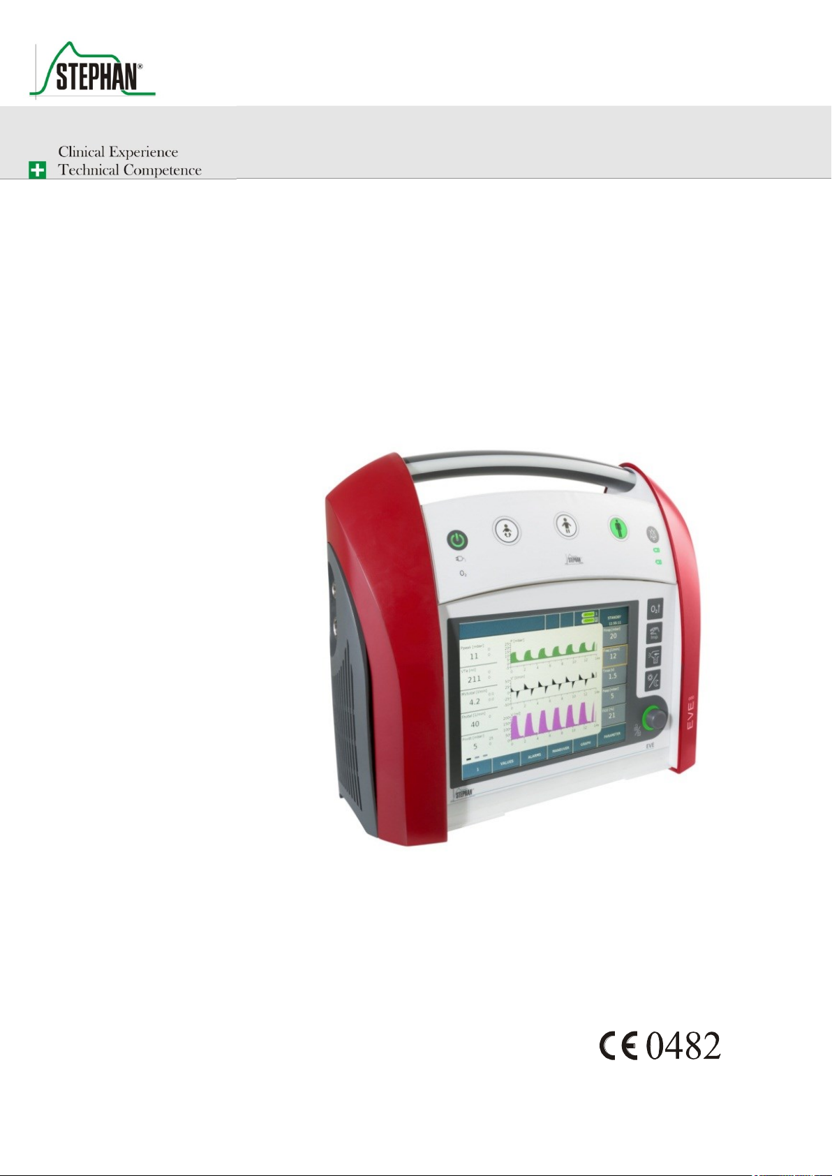
EVE
TR
Transport Ventilator
Instructions for use
Page 2
Preface
2
GA-070T-0518V2.7-HAO-EN
Fritz Stephan GmbH
NOTE
For information about the maintenance and care of the EVETR, please see the service
manual. This also contains detailed information about the device design and function
as well as its individual components.
NOTE
Fritz Stephan GmbH offers training on the safe and efficient use of the
EVE ventilator. Training material can also be requested. Please contact
[email protected] for more information.
Fritz Stephan GmbH Equipment is subject to technical modification.
- Medizintechnik -
Kirchstraße 19 Valid as of: May 2018
Version: V2.7
D-56412 Gackenbach From software version: V2.2
Art. no.: 107090011
This manual aims to provide clear answers to your questions about the
operation and care of the EVETR. It does not contain any information
about repairs, installation or hazards that are clearly observable by the
user or caused by the non-intended use of or non-authorized
modifications to the device.
If any malfunctions occur while operating the device, please contact the
authorized FRITZ STEPHAN GMBH customer service team or the
authorized specialist dealer who supplied the device and familiarized you
with its function and operation.
The manufacturer only guarantees the safety and reliability of the EVETR
when it is operated according to the manual.
Page 3

®
Table of contents
Fritz Stephan GmbH
GA-070T-0518V2.7-HAO-EN
3
Table of contents
Table of contents ........................................................................................ 3
1 General information ........................................................................... 9
1.1 Product combination .............................................................. 10
1.2 Optional components ............................................................. 12
1.3 Device name and manufacturer ............................................. 12
1.4 Intended use ........................................................................... 13
1.5 Contraindications ................................................................... 14
1.6 Disposal ................................................................................. 14
1.7 Introduction ........................................................................... 15
1.8 Abbreviations, definitions, and pictograms ........................... 16
1.9 Specifications ......................................................................... 22
1.2.1 Software components ................................................ 12
1.2.2 Hardware components ............................................... 12
2 Safety instructions ............................................................................ 33
2.1 Danger ................................................................................... 34
2.2 Warning ................................................................................. 35
3 Design and functional description.................................................... 41
3.1 Front view .............................................................................. 41
3.1.1 Alarm indicator ......................................................... 42
3.1.2 Control panel ............................................................. 43
3.1.3 Function buttons ........................................................ 46
3.2 Touchscreen monitor ............................................................. 49
3.2.1 General information about touchscreen navigation ... 50
Selecting a function field ................................. 50 3.2.1.1
Setting options and parameters ........................ 51 3.2.1.2
Functions in the System Settings menu ........... 52 3.2.1.3
3.2.2 Measured value display ............................................. 54
3.2.3 Function fields ........................................................... 57
Measured value indicator switch ...................... 57 3.2.3.1
Values .............................................................. 57 3.2.3.2
Alarms .............................................................. 59 3.2.3.3
Maneuver ......................................................... 66 3.2.3.4
Graph ................................................................ 68 3.2.3.5
Page 4

Table of contents
4
GA-070T-0518V2.7-HAO-EN
Fritz Stephan GmbH
Parameter ......................................................... 68 3.2.3.6
3.2.4 Parameter display ...................................................... 69
3.2.5 Ventilation mode display .......................................... 70
3.2.6 Energy supply indicator ............................................ 71
3.2.8 Status, alarm and info display ................................... 73
3.2.9 Graphic display ......................................................... 74
Configuring the measurement curves ............... 75 3.2.9.1
Configuration of loops and trends .................... 76 3.2.9.2
3.3 Left side view ........................................................................ 79
3.4 Right side view ...................................................................... 80
3.6 Rear view ............................................................................... 82
3.7 Brackets ................................................................................. 83
3.7.1 Ambulance bracket .................................................... 83
3.7.2 Helicopter bracket ..................................................... 84
3.7.3 Carry system .............................................................. 85
Built-in pressure regulator ............................... 85 3.7.3.1
4 System Settings ................................................................................ 87
4.1 System ................................................................................... 88
4.1.1 Info ............................................................................ 89
4.1.2 Display ...................................................................... 89
4.1.3 Time and Date ........................................................... 89
4.1.4 Function ..................................................................... 90
4.2 Sensors ................................................................................... 91
4.2.1 Pulse oximetry ........................................................... 91
Settings ............................................................. 92 4.2.1.1
Parameter ......................................................... 93 4.2.1.2
SpO2 ................................................................. 94 4.2.1.3
SpHb ................................................................ 95 4.2.1.4
4.2.2 Capnometry ............................................................... 96
4.2.3 Flow ........................................................................... 97
4.2.4 Ventilation tube system ............................................. 98
4.3 Display ................................................................................... 99
4.3.1 Measured values ........................................................ 99
4.4 Setup .................................................................................... 100
4.4.1 Oxygen configuration .............................................. 101
4.4.2 I:E/Tinsp .................................................................. 102
Page 5

®
Table of contents
Fritz Stephan GmbH
GA-070T-0518V2.7-HAO-EN
5
4.4.3 Language ................................................................. 103
4.4.4 Touchscreen calibration .......................................... 103
4.4.5 Factory Settings ....................................................... 103
4.4.6 Service Software ..................................................... 103
4.4.7 Deep Sleep mode ..................................................... 104
4.4.8 Sound ....................................................................... 104
4.4.9 Logbook .................................................................. 105
4.4.10 License .................................................................... 105
5 Preparation for use ......................................................................... 107
5.1 Connecting the oxygen supply............................................. 107
5.1.1 Connecting the oxygen cylinder .............................. 108
5.1.2 Sample calculation: O2 oxygen consumption .......... 110
5.1.3 Changing the oxygen cylinder ................................. 111
5.1.4 Connection to the central gas supply ....................... 112
5.1.5 Connecting to an oxygen concentrator .................... 112
5.2 Energy supply connection.................................................... 113
5.2.1 Mains power supply ................................................ 113
5.2.2 12/24 V mains power supply ................................... 113
5.2.3 Internal energy supply ............................................. 114
5.2.4 Charging the external battery .................................. 115
5.3 Connecting the patient tube system ..................................... 115
5.3.1 EVE adults emergency single-use tube system ....... 116
5.3.2 EVE pediatric single-use tube system ..................... 117
5.3.3 Configuration for use of the EasyFlow nCPAP system118
5.4 Installing the expiration valve ............................................. 118
5.4.1 Connecting the distal expiration valve .................... 119
5.4.2 Connecting the proximal expiration valve .............. 119
5.5 Installing the flow sensor ..................................................... 119
5.6 Installing the patient filter .................................................... 120
5.7 Installing the SpO2 sensor .................................................... 121
5.8 Aerosol nebulization ............................................................ 121
6 Operation ....................................................................................... 125
6.1 Test before every start-up .................................................... 125
6.1.1 Testing requirements ............................................... 125
6.1.2 Test list .................................................................... 126
6.2 Switching the device on/off ................................................. 127
Page 6

Table of contents
6
GA-070T-0518V2.7-HAO-EN
Fritz Stephan GmbH
6.3 Selftest ................................................................................. 127
6.3.1 Selftest passed ......................................................... 127
6.3.2 Selftest failed ........................................................... 128
6.4 Standby mode ...................................................................... 129
6.5 Using fast tracking keys ...................................................... 129
6.6 New Patient.......................................................................... 130
6.7 Ventilation tube system ....................................................... 131
6.7.1 Default ventilation parameters ................................ 132
6.8 Mode Settings ...................................................................... 133
6.8.1 Monitoring ............................................................... 135
6.8.2 Selecting the ventilation mode ................................ 136
6.9 Ending ventilation ................................................................ 138
7 Ventilation modes .......................................................................... 139
7.1 Invasive and non-invasive ventilation modes ...................... 139
7.2 Trigger functionality ............................................................ 142
7.2.1 Flow trigger ............................................................. 142
7.2.2 Internal flow trigger ................................................ 142
7.3 Mandatory ventilation .......................................................... 143
7.3.1 Volume-controlled ventilation ................................ 144
Volume-controlled continuous mandatory 7.3.1.1
ventilation (VC-CMV) ................................... 144
Volume-controlled synchronized intermittent 7.3.1.2
mandatory ventilation (VC-SIMV) ................ 146
7.3.2 Pressure-controlled ventilation modes .................... 149
Pressure-controlled continuous mandatory 7.3.2.1
ventilation (PC-CMV).................................... 149
Non-invasive pressure-controlled mandatory 7.3.2.2
ventilation (nPC-CMV) .................................. 151
Pressure-controlled synchronized intermittent 7.3.2.3
mandatory ventilation (PC-SIMV) ................. 152
Non-invasive pressure-controlled synchronized 7.3.2.4
intermittent mandatory ventilation (nPC-SIMV)155
Pressure-controlled assist/control ventilation 7.3.2.5
(PC-ACV) ...................................................... 156
Non-invasive pressure-controlled assist/control 7.3.2.6
ventilation (nPC-ACV) .................................. 157
Pressure-controlled assist/control ventilation + 7.3.2.7
(PC-ACV+) .................................................... 158
Page 7

®
Table of contents
Fritz Stephan GmbH
GA-070T-0518V2.7-HAO-EN
7
Non-invasive pressure-controlled assist/control 7.3.2.8
ventilation plus (nPC-ACV+) ........................ 158
DUOPAP ........................................................ 159 7.3.2.9
Non-invasive DUOPAP (nDUOPAP)............ 162 7.3.2.10
7.3.3 Spontaneous breathing ............................................ 163
CPAP .............................................................. 163 7.3.3.1
nCPAP ............................................................ 165 7.3.3.2
7.3.4 O2 therapy ................................................................ 166
7.3.5 High flow O2 therapy .............................................. 166
7.4 Additional options for ventilation modes ............................ 167
7.4.1 Pressure-regulated and volume-controlled ventilation
(PRVC) .................................................................... 167
7.4.2 Pressure support ventilation (PSV) ......................... 169
7.4.3 Tube compensation ................................................. 171
8 CO2 measurement (optional) .......................................................... 173
8.1 Measurement using the mainstream technique .................... 174
8.1.1 Intended use............................................................. 174
8.1.2 Specifications .......................................................... 175
8.1.3 Warnings ................................................................. 175
8.1.4 Installing the CO2 measuring probe ........................ 178
8.1.5 Running zero calibration ......................................... 181
8.1.6 Probe status indicator .............................................. 182
8.1.7 Cleaning the probe .................................................. 182
8.2 Measurement using the sidestream technique ..................... 182
8.2.1 Intended use............................................................. 183
8.2.2 Specifications .......................................................... 183
8.2.3 Warnings ................................................................. 184
8.2.4 Installing the ISA™ CO2 analyzer .......................... 188
8.2.5 Running zero calibration ......................................... 190
8.2.6 Status indicator of the analysis adapter ................... 190
8.2.7 Cleaning the CO2 analyzer ...................................... 191
9 Functional description .................................................................... 193
10 Troubleshooting ............................................................................. 195
10.1 List of errors ........................................................................ 195
10.2 Selftest error ........................................................................ 208
10.3 Moisture in the PNT B (flow sensor) .................................. 209
11 Care and maintenance .................................................................... 211
Page 8

Table of contents
8
GA-070T-0518V2.7-HAO-EN
Fritz Stephan GmbH
11.1 Disinfection and sterilization ............................................... 211
11.2 Information about cleaning agents and disinfectants ........... 212
11.3 Automated cleaning and disinfection .................................. 213
11.4 Manual cleaning and disinfection ........................................ 215
11.5 Cleaning and disinfection of device surfaces ...................... 216
11.6 Sterilization .......................................................................... 217
11.7 Carrying out the treatment ................................................... 218
11.7.1 Type B Pneumotachograph (flow sensor) ............... 218
Preparing the PNT B ...................................... 220 11.7.1.1
11.7.1.2
11.7.2 Test lung Neo with tube adapter .............................. 224
11.8 Treatment table .................................................................... 226
11.9 Safety checks ....................................................................... 227
11.10 Maintenance ......................................................................... 227
11.11 Servicing .............................................................................. 228
11.11.1 Procedure ................................................................. 230
12 Electromagnetic emissions and immunity ..................................... 235
12.1 Electromagnetic emissions .................................................. 235
12.2 Electromagnetic immunity................................................... 236
12.3 Recommended separation distance ...................................... 239
13 Accessory list ................................................................................. 241
14 Warranty ........................................................................................ 245
Post-treatment ................................................ 221
Replacing the coarse filter ......................... 230 11.11.1.1
Replacing the HEPA filter ......................... 231 11.11.1.2
Replacing the fan filter .............................. 231 11.11.1.3
Replacing the external battery ................... 233 11.11.1.4
15 List of figures ................................................................................. 247
16 List of tables ................................................................................... 251
17 Notes .............................................................................................. 253
Page 9
®
1 General information
Fritz Stephan GmbH
GA-070T-0518V2.7-HAO-EN
9
ATTENTION
Do not reuse disposable accessories!
The necessary reconditioning may lead to the deterioration of mechanical and
biological product properties, posing a significant risk to the patient. In addition,
reusing such accessories dangerously increases the risk of contamination for the
patient.
ATTENTION
The sole responsibility for selecting a suitable patient monitoring system that provides
reliable data about the correct functioning of the medical device and the condition of
the patient lies with the user of the ventilator. Different techniques can be used to
monitor patient safety, from the electronic monitoring of the correct functioning of the
medical device and the condition of the patient to simple direct observation of the
patient. The sole responsibility for selecting a suitable patient monitoring technique
lies with the user.
ATTENTION
All electrical cables and gas connections connected to the medical device must
comply with applicable standards.
NOTE
The applied parts of the EVE (CO2 sensor, SpO2 sensor and ventilator breathing
system (VBS)) are protected against defibrillation.
For the SpO2 and CO2 module, the recovery time is under 5 seconds.
1 General information
FRITZ STEPHAN GMBH disclaims any warranty with respect to the
operation of unauthorized device combinations with products not
approved by the manufacturer or without certified compatibility.
Page 10

1 General information
10
GA-070T-0518V2.7-HAO-EN
Fritz Stephan GmbH
Certified product
combinations
1.1 Product combination
FRITZ STEPHAN GMBH disclaims any warranty with respect to the
operation of unauthorized device combinations with products not
approved by the manufacturer or without certified compatibility.
1. Medication nebulizer
Pneumatic medication nebulizer 22m/22f
Manufacturer: GaleMed
2. Flow sensors
Flow sensor, adults
Manufacturer: Fritz Stephan GmbH
Flow sensor, children
Manufacturer: Fritz Stephan GmbH
Pneumotachograph, preterm infants and newborns, type B
for ventilator EVE
Manufacturer: Fritz Stephan GmbH
Pressure measuring adapter nCPAP
Manufacturer: Fritz Stephan GmbH
3. Disposable patient tube systems
EVE adult emergency
Manufacturer: Fritz Stephan GmbH
EVE paediatrics
Manufacturer: Fritz Stephan GmbH
EVE adult ICU
Manufacturer: Fritz Stephan GmbH
Patient tube system 10 mm, newborn, heated
Manufacturer: WILAmed
Patient tube system 15 mm, child, heated
Manufacturer: WILAmed
Patient tube system 22 mm, adult, heated
Manufacturer: WILAmed
Patient tube system RT 265, child, heated
Manufacturer: Fisher & Paykel
Patient tube system RT 380, adult, heated
Manufacturer: Fisher & Paykel
Patient tube system RT330 Optiflow Junior, heated
Manufacturer: Fisher & Paykel
Ventilation tube RT024
Manufacturer: Fisher & Paykel
Page 11

®
1 General information
Fritz Stephan GmbH
GA-070T-0518V2.7-HAO-EN
11
NOTE
Further information on the accessories for the ventilator can be found in chapter 13.
4. NCPAP patient interfaces
EasyFlow NCPAP system
Manufacturer: Fritz Stephan GmbH
5. Expiration valve
Manufacturer: Fritz Stephan GmbH
CO2 sensor
Manufacturer: Masimo
6. Masimo Rainbow
Manufacturer: Masimo
7. Optiflow Junior Nasal Cannula
Manufacturer: Fisher & Paykel
8. Optiflow + Nasal Cannula
Manufacturer: Fisher & Paykel
Page 12

1 General information
12
GA-070T-0518V2.7-HAO-EN
Fritz Stephan GmbH
Device name
Manufacturer
1.2 Optional components
1.2.1 Software components
On customer request, EVETR can also be equipped with the following
software components:
License graphic (loops & trends), art. no.: 107061451
License Neo mode, art. no.: 107061460
License Niv / Duopap, art. no.: 107061450
License ACV+/nACV+, art. no.: 107061452
1.2.2 Hardware components
The EVETR can optionally be equipped with a CO2 measurement using
the mainstream or sidestream technique (see chapter 8) as well as a pulse
oximeter for measuring the Masimo Rainbow® parameters Pulse, PVI,
PI, SpMet, SpCO, and SpOC (see supplemental pulse oximetry manual).
1.3 Device name and manufacturer
EVETR
Fritz Stephan GmbH
- Medizintechnik Kirchstraße 19
D-56412 Gackenbach
Page 13

®
1 General information
Fritz Stephan GmbH
GA-070T-0518V2.7-HAO-EN
13
Ventilation mode
Standard
Optional
PC-CMV
X
-
PC-SIMV
X
-
PC-ACV
X
-
PC-ACV+
-
License ACV+/nACV+
required
CPAP
X
-
VC-CMV
X
-
VC-SIMV
X
-
O2 therapy
X
-
High flow
O2 therapy
-
License Neo mode
required
DUOPAP
-
License Neo mode or
NIV-DUOPAP required
nPCMV
-
License Neo mode
required
nPC-SIMV
-
License Neo mode
required
nPC-ACV
-
License Neo mode
required
nPC-ACV+
-
License ACV+/nACV+
required
nDUOPAP
-
License Neo mode or
NIV-DUOPAP required
nCPAP
-
License Neo mode
required
Therapeutic scope
1.4 Intended use
The EVETR is used for invasive and non-invasive ventilation in emergency
and transport settings. The EVETR is suitable for long-term ventilation.
The ventilator is available in different feature levels and can be used by
first responders as well as for ground, water, or air transport. The EVETR
is suitable for the ventilation of children and adults weighing up to
200 kg. It is also possible to ventilate preterm infants and newborns.
The EVETR supports the following types of ventilation:
Tab. 1: Therapeutic scope
Page 14
1 General information
14
GA-070T-0518V2.7-HAO-EN
Fritz Stephan GmbH
WARNING
Risk of explosion!
Do not throw the battery into a fire or open it with force!
NOTE
Before disposing of the device or any of its components, these must be cleaned and
disinfected.
Infectious disposable accessories must be disposed of as specified in the operating
manual!
Disposal of the
packaging
Disposal of the device
and the battery
1.5 Contraindications
The safety instructions provided in chapter 2 must be observed. No
additional contraindications exist.
It is the sole responsibility of the user to select the most appropriate type
of ventilation based on the patient's medical condition. The continuous
monitoring of the patient's condition must be assured at all times.
Non-invasive ventilation is contraindicated in the following cases:
No spontaneous breathing
Fixed or functional airway obstruction
Gastrointestinal bleeding or ileus
1.6 Disposal
The device packaging largely consists of recyclable or reusable materials.
The cardboard packaging can be reused or disposed of as used paper.
FRITZ STEPHAN GMBH will accept the return of any used devices from
our company free of charge and dispose of these correctly, thus making a
contribution to the environment.
Used batteries and the device itself must not be disposed of as domestic
waste. Proper disposal must be conducted by a certified electrical and
electronic waste recycling company. Disposal via municipal collection
points for waste electrical equipment is not permitted!
Page 15

®
1 General information
Fritz Stephan GmbH
GA-070T-0518V2.7-HAO-EN
15
NOTE
The EVETR must be operated from the front side. The operator must have a sufficient
visual angle of the control and display elements.
Warranty
1.7 Introduction
Device setup, operation, and maintenance is only permitted by trained
personnel. All relevant national laws, guidelines, and regulations as well
as the following instructions must be observed:
The device must be operated by trained personnel only. Thorough
knowledge of the operating manual is required.
Only use the device for the intended purpose described in the
operating manual.
Read the operating manual carefully and comply with its
instructions; lasting safety for the patient and user is only ensured
when the device is operated correctly.
The operating manual must be kept readily available at the place
of use.
Inadequate care and incorrect operation can cause downtime and
accidents.
The manufacturer does not accept any warranty claims resulting from
incorrect operation or inadequate care and maintenance.
The manufacturer only guarantees the safety and reliability of the device
if it is operated in compliance with the operating manual.
Page 16

1 General information
16
GA-070T-0518V2.7-HAO-EN
Fritz Stephan GmbH
Abbreviation/
technical
term
Term
Meaning
Battery
Device for storing electrical energy in the
form of chemical energy
Apnea
Respiratory arrest
BTPS
Body Temperature Pressure Saturated
Measuring condition at body temperature,
current ambient pressure and saturated gas
CPAP
Continuous Positive Airway Pressure
Spontaneous breathing with continuous
positive airway pressure.
When breathing under CPAP, the device keeps
the pressure constant on the endotracheal
tube’s connection piece.
Distal
Away from the patient
DUOPAP
Ventilation support at two different pressure
levels
ETT
Endotracheal tube
Exp
Expiration (exhalation)
Time period from the onset of the expiration
flow until the onset of the inspiration flow
Flow limit
Flow limitation
Limitation of the flow for non-invasive
ventilation in NEO mode
HEPA
High Efficiency Particulate Air Filter
High-performance particle filter
HME
Heat and Moisture Exchanger
Heat and moisture exchanger
HP
High priority
An alarm indicating that the user should
intervene without delay. (IEC 60601-1-8)
HW
Notification
IGR
Incremental encoder
Control knob for device operation
Insp
Inspiration (inhalation)
Time period from the onset of the inspiration
flow until the onset of the expiration flow
MP
Medium priority
An alarm indicating that the user should
intervene immediately. (IEC 60601-1-8).
1.8 Abbreviations, definitions, and pictograms
Page 17

®
1 General information
Fritz Stephan GmbH
GA-070T-0518V2.7-HAO-EN
17
Abbreviation/
technical
term
Term
Meaning
nCPAP
Non-invasive continuous positive
airway pressure
Non-invasive spontaneous breathing with
continuous positive airway pressure.
When breathing under CPAP, the device keeps
the pressure constant on the endotracheal
tube’s connection piece.
nPC-CMV
Non-invasive pressure-controlled
mandatory ventilation
Non-invasive pressure-controlled mandatory
ventilation
nPC-SIMV
Non-invasive pressure-controlled
synchronized intermittent mandatory
ventilation
Non-invasive pressure-controlled
synchronized intermittent mandatory
ventilation
nPC-ACV
Non-invasive pressure-controlled –
Assist Control Ventilation
Non-invasive pressure-controlled
assist/control ventilation
nPC-ACV+
Non-invasive pressure-controlled –
Assist Control Ventilation with
expiration trigger
Non-invasive pressure-controlled
assist/control ventilation with expiration
trigger
nDUOPAP
Non-invasive ventilation support at two
different pressure levels
NIST
Non-interchangeable screw thread
Non-interchangeable screw thread
O2 Oxygen level
PC-CMV
Pressure controlled mandatory
ventilation
Pressure controlled mandatory ventilation
PC-SIMV
Pressure controlled synchronized
intermittent mandatory ventilation
Pressure-controlled synchronized intermittent
mandatory ventilation
PC-ACV+
Pressure Controlled – Assist Control
Ventilation with expiration trigger
Pressure-controlled assist/control ventilation
with expiration trigger
PC-ACV
Pressure Controlled – Assist Control
Ventilation
Pressure-controlled assist/control ventilation
PI Perfusion index
PRVC
Pressure regulated volume control
Pressure-controlled and volume-regulated
ventilation
PSV
Pressure support ventilation
Pressure support ventilation
PVI™
Pleth Variability Index
Plethysmographic variability index
PEEP
Positive End Expiratory Pressure
Positive end expiratory pressure
Pinsp
Inspiratory pressure
Page 18

1 General information
18
GA-070T-0518V2.7-HAO-EN
Fritz Stephan GmbH
Abbreviation/
technical
term
Term
Meaning
PAW
Airway pressure
Pmean
Mean airway pressure
PNT
Pneumotachograph
Flow sensor
Proximal
Close to the patient
Resistive
Creates a pneumatic resistance
SIMV
Synchronized Intermittent Mandatory
Ventilation
Form of ventilation synchronized to the patient
SpCO®
Carboxyhemoglobin measurement
Index for CO level in arterial blood
SpMet™
Methemoglobin measurement
Index for methemoglobin level in arterial
blood
SpHb®
Hemoglobin measurement
Index for hemoglobin level in arterial blood
SpOC®
Oxygen level measurement
Index for oxygen level in arterial blood
Standby
The device is ready for use
STPD
Standard temperature, pressure, dry
Measuring condition at standard temperature
(20 C), standard pressure (1013 mm Hg
absolute), dry
TA Technical alarm
TC
Tube compensation
Tube compensation
V´
Flow
Volume flow
VC-CMV
Volume-controlled continuous
mandatory ventilation
Volume-controlled continuous mandatory
ventilation
VC-SIMV
Volume-controlled synchronized
intermittent mechanical ventilation
Volume-controlled synchronized intermittent
mechanical ventilation
PU Packaging unit
VT
Tidal volume
Breathing volume
VTe
Expiratory breathing volume
Expiratory tidal volume
CGS
Central gas supply
V Volume
Tab. 2: Abbreviations and technical terms
Page 19
®
1 General information
Fritz Stephan GmbH
GA-070T-0518V2.7-HAO-EN
19
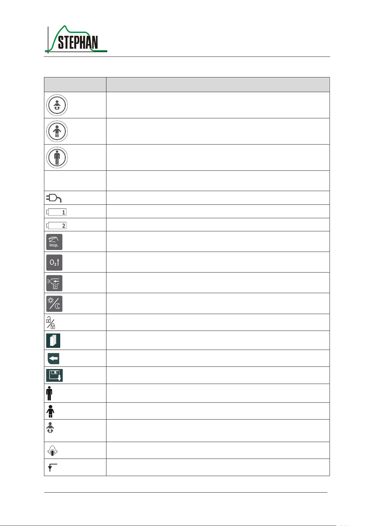
Pictogram
Meaning
Standard ventilation parameter for premature infants and newborns
(see chapter 3.1.2)
Standard ventilation parameter for children (see chapter 3.1.2)
Standard ventilation parameter for adults (see chapter 3.1.2)
O
2
O2 supply indicator (see chapter 3.1.2)
Mains power indicator (see chapter 3.1.2)
Charge indicator for battery 1 (see chapter 3.1.2)
Charge indicator for battery 2 (see chapter 3.1.2)
Inspiration hold (see chapter 3.1.3)
Pre-oxygenation (see chapter 3.1.3)
Activate aerosol nebulization (see chapter 3.1.3)
Day/Night toggle switch (see chapter 3.1.3)
Lock/unlock touchscreen (see chapter 3.1.3)
Scroll (see chapter 3.2.3)
Return (see chapter 3.2.1.3)
Save settings (see chapter 3.2.1.3)
Ventilation settings for adults pre-selected (see chapter 3.2.5)
Ventilation settings for children pre-selected (see chapter 3.2.5)
Ventilation settings for preterm infants and newborns preselected
(see chapter 3.2.5)
Non-invasive ventilation (see chapter 3.2.5)
Invasive ventilation (see chapter 3.2.5)
Page 20
1 General information
20
GA-070T-0518V2.7-HAO-EN
Fritz Stephan GmbH
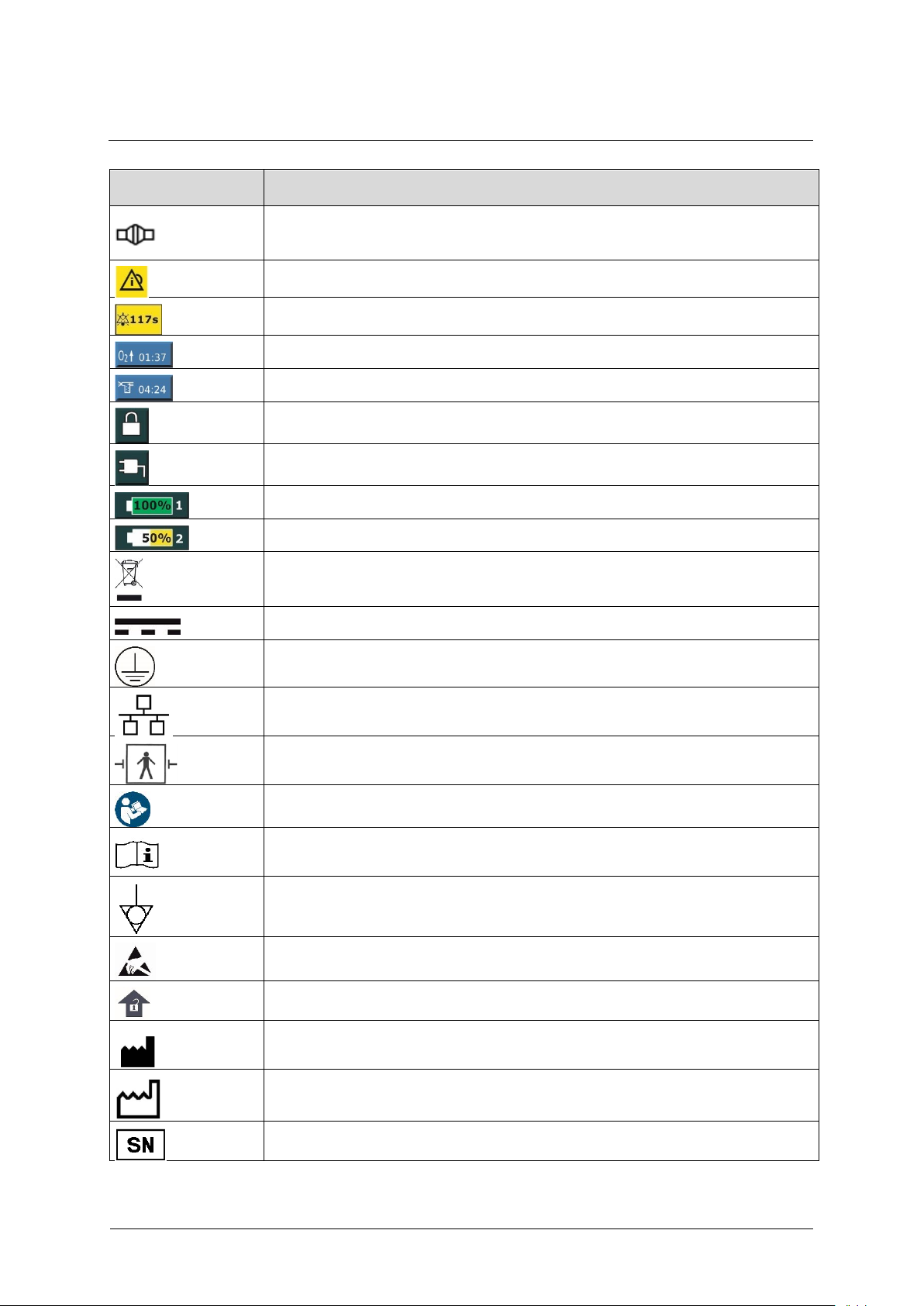
Pictogram
Meaning
PNT (see chapter 3.2.5)
Alarm history contains unacknowledged alarms (see chapter 3.2.8)
Alarm suppression switched on (see chapter 3.2.8)
Pre-oxygenation activated (see chapter 3.2.8)
Aerosol nebulization activated (see chapter 3.2.8)
Touchscreen locked (see chapter 3.2.7)
Mains power (see chapter 3.2.6)
Charge level for battery 1 (see chapter 3.2.6)
Charge level for battery 2 (see chapter 3.2.6)
Contains conventional or rechargeable batteries and must not be disposed of as
domestic waste.
DC
Protective conductor
Ethernet port
Type BF applied part, defibrillator-protected
The instructions in the operating manual must be observed
Read operating manual
Equipotential bonding
Hazard symbol for ESD-sensitive parts
Push lever up to unlock
Manufacturer
Manufacturing date
Serial number
Page 21
®
1 General information
Fritz Stephan GmbH
GA-070T-0518V2.7-HAO-EN
21
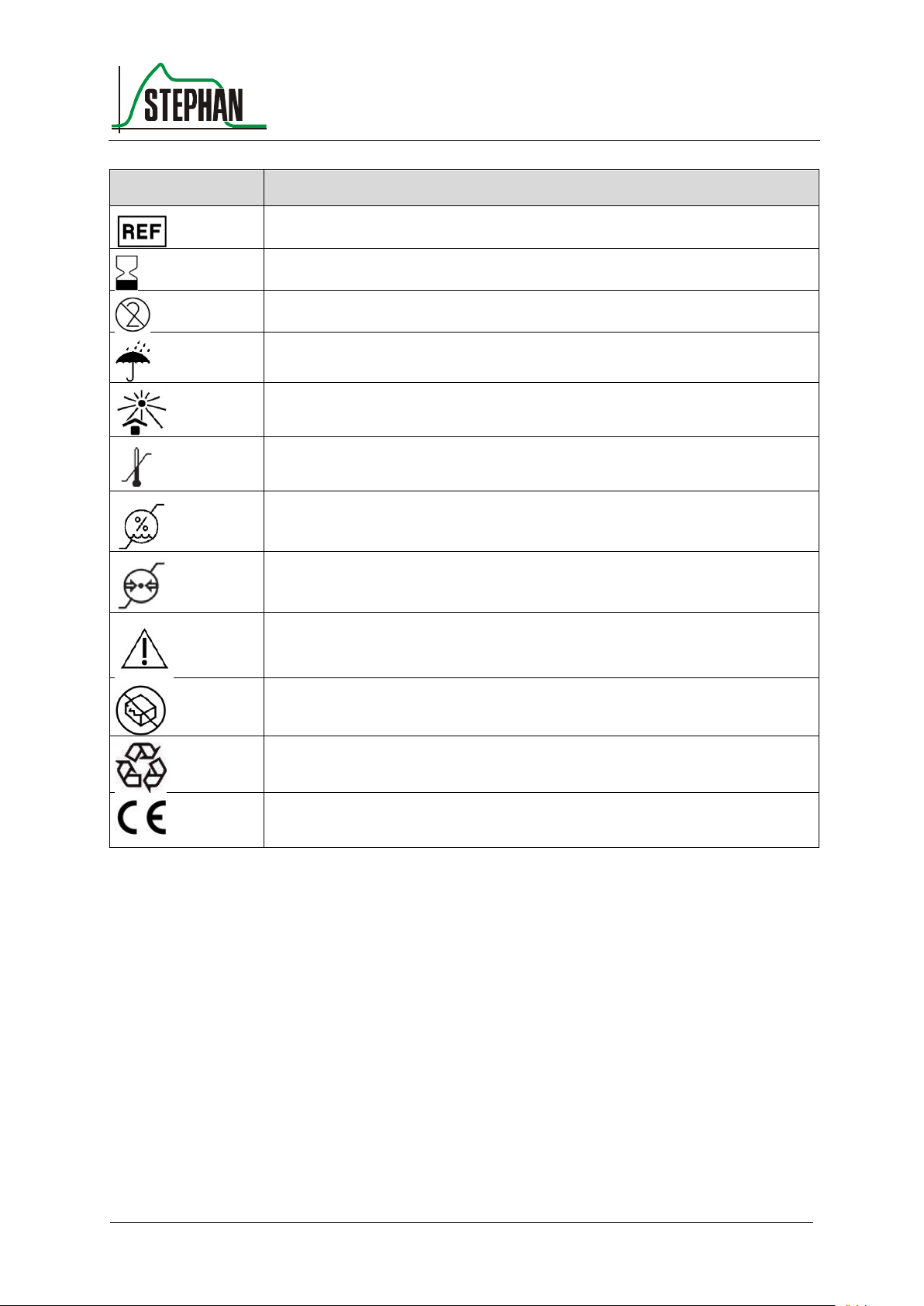
Pictogram
Meaning
Product number
Expiration date
Do not reuse
Keep dry
Keep away from sunlight
Temperature limits for storage and transport
Humidity limits for storage and transport
Atmospheric pressure limits for storage and transport
Warning
Do not use if the packaging is damaged
Recyclable materials
CE marking, indicates compliance with Directive 93/42/EEC concerning
medical devices
Tab. 3: Pictograms
Page 22

1 General information
22
GA-070T-0518V2.7-HAO-EN
Fritz Stephan GmbH
Operation
Temperature
−10 – 40° C
Relative humidity
5 – 95%
(non-condensing)
Air pressure
540 – 1100 hPa
Storage
Temperature
−20 – 50° C
Relative humidity
10 – 80%
(non-condensing)
Air pressure
540 – 1100 hPa
Store in a protected, dust-free location protected
from humidity.
Class according to
93/42/EEC
II b
Protection type
IP 44
Protection against contact with tools, conductive
parts with a diameter > 1.0 mm; protection
against foreign objects with a diameter > 1.0 mm
Protected against splash water from any
direction
UMDNS code
18-098
GMDN code
36289
Inspection/
maintenance cycle
Annually
Dimensions
(WxHxD)
360 x 320 x 155 mm
Weight
Main device without
external battery
6.3 kg
Main device with
external battery
6.9 kg
Sound pressure level
46 dB (A)
Sound power level
56 dB
Maximum pressure
limit
P
LIM,
max
100 mbar (SFC)
Ambient conditions
General information
1.9 Specifications
Page 23

®
1 General information
Fritz Stephan GmbH
GA-070T-0518V2.7-HAO-EN
23
Mains
Connection
100 – 240 V AC
50 – 60 Hz
Protection class
II according to IEC 60601-1
Supply line
Power supply
Power consumption
Max. 150 W
Current consumption
1.667 – 0.625 A
Battery
Type
Lithium-ion
Nominal voltage
25.2 V DC
Nominal capacity
2.1 Ah
Operating time
(with optional external
battery)
(new batteries,
fully charged)
Max. 6 hours/
min. 3.5 hours
Battery 1 (internal)
Max. 3 hours
Battery 2 (external),
optional
Max. 3 hours
Charge time battery 1
Approx. 3 hours
Charge time battery 2
Approx. 4 hours
Batteries 1 and 2 are only charged at a battery
temperature of 0 – 40° C.
NOTE
The battery life of the ventilator is reduced at extreme temperatures.
Ambulance bracket
Dimensions
380 x 360 x 118 mm (W x H x D)
Weight
3.5 kg
Connections:
12 – 28 V DC
Energy supply
Brackets
Page 24

1 General information
24
GA-070T-0518V2.7-HAO-EN
Fritz Stephan GmbH
Helicopter bracket
Dimensions
426 x 360 x 150 mm (W x H x D)
Weight
3.3 kg
Connections:
12 – 28 V DC
Carry system without gas cylinder and pressure regulator
Dimensions
470 x 335 x 260 mm (W x H x D)
Weight
2.7 kg
Supply pressure
High pressure
O2
280 – 600 kPa
Flow rate
Max. 200 l/min
Gas consumption
Conventional (see chapter 5.1.2 for more
information about O2 gas consumption)
Aerosol
Approx. 7 l/min
at 2.8 bar
The gases must be dry and free of oil and dust.
PC-CMV
Pressure-controlled continuous mandatory ventilation
PC-SIMV
Pressure-controlled synchronized intermittent mandatory
ventilation
PC-ACV
Pressure-controlled assist/control ventilation
PC-ACV+
Pressure-controlled assist/control ventilation with
expiration trigger
CPAP
Spontaneous respiration with continuous positive airway
pressure
DUOPAP
Ventilation support at two different pressure levels
VC-CMV
Volume-controlled continuous mandatory ventilation
VC-SIMV
Volume-controlled synchronized intermittent
mechanical ventilation
nPC-CMV
Non-invasive pressure-controlled mandatory ventilation
nPC-SIMV
Non-invasive pressure-controlled synchronized
intermittent mandatory ventilation
Gas supply
Available
ventilation modes
Page 25

®
1 General information
Fritz Stephan GmbH
GA-070T-0518V2.7-HAO-EN
25
nPC-ACV
Non-invasive pressure-controlled assist/control
ventilation
nPC-ACV+
Non-invasive pressure-controlled assist/control
ventilation with expiration trigger
nDUOPAP
Non-invasive ventilation support at two different
pressure levels
nCPAP
Non-invasive spontaneous breathing with continuous
positive airway pressure
Parameter
Setting range
Resolution
Pre-oxygenation (time)
10 – 180 s
1
Pre-oxygenation (concentration)
21 – 100%
1
Insp. Hold
Max. 15 s
1
Aerosol
5 – 30 min
5
Parameter
Meaning
Setting range
Resolution
PEEP
Positive end expiratory
pressure
0 – 25 mbar
1
Pinsp*
Inspiratory pressure
6 – 55 mbar
1
Psupp
Support pressure
1 – 55 mbar
Phigh*
Inspiratory pressure
under DUOPAP
6 – 55 mbar
1
VT
Tidal volume
(PC mode / PRVC)
2 – 150 ml
1
150 – 500 ml
5
500 – 1000 ml
10
1000 – 2000 ml
50
VT
Tidal volume
(volume-controlled
ventilation)
100 – 150 ml
1
150 – 500 ml
5
500 – 1000 ml
10
1000 – 2000 ml
50
Flow limit
Flow limitation
5 -30 / Off l/min
1
Tinsp
Inspiration time
0.2 – 30 s
0.1
Texp
Expiration time
0.2 – 30 s
0.1
Function keys
Ventilation parameters
Page 26

1 General information
26
GA-070T-0518V2.7-HAO-EN
Fritz Stephan GmbH
Parameter
Meaning
Setting range
Resolution
I:E
Inspiration/
expiration ratio
1:150, 150:1
1
f
Frequency
1 – 150 1/min
1
Apnea
Apnea duration
1 – 60 s
1
O2
O2 ratio of breathing air
21 – 100%
1
Trigger
Flow trigger
0.2 – 15 l/min
0.1
Ramp time
Ramp time
0.06 – 30 s
0.01
Flow
Flow O2 therapy
2 – 20 l/min
1
ETS
Expiration trigger
sensitivity
5 – 70%
1
Tube
compensation
Intensity of tubus
compensation
0 – 100%
1
Tube Ø
Tube diameter
2 – 12 mm
0.5
Measured value
Unit
Resolution
Display range
Pressure (accuracy1: P = 2 mbar + 4% of displayed value)
Ppeak
mbar
1
−20 – 99
Pplat
mbar
1
−20 – 99
Pmean
mbar
1
−20 – 99
PEEP
mbar
1
−20 – 99
Flow (STPD, accuracy1: V` = 15%)
V´min
l/min
0.1
−200 – 200
V´max
l/min
0.1
−200 – 200
Volume
(STPD, accuracy1: V = 4.0 ml +15%)
VTe
ml 1 0 – 3000
VTspon
ml 1 0 – 3000
VTleak
ml 1 0 – 100
MVe
l/min
0.01
0 – 999
MVspon
l/min
0.01
0 – 999
1
Monitoring
* Ensured by using a redundant pressure measurement and limitation
Accuracy assumes an ambient temperature of 0 – 40° C.
Page 27

®
1 General information
Fritz Stephan GmbH
GA-070T-0518V2.7-HAO-EN
27
Measured value
Unit
Resolution
Display range
Time (accuracy1: t` = 5%)
Tinsp
s
0.1
0 – 60
Texp
s
0.1
0 – 60
ftotal
1/min
1
0 – 300
fspon
1/min
1
0 – 300
I:E
I:E
0.1
1:150 – 150:1
O
2
(calculation accuracy1: 2.5 Vol.% + 2.5% of displayed value)
O2 % 1
21 – 100
Rise time of O2 level from 21% to
90%
58 s (VT = 30 ml)
37 s (VT = 150 ml)
22 s (VT = 500 ml)
EtCO
2
(see manufacturer data sheet for sensor accuracy)
EtCO2
Vol%
0.1
0 – 90
mmHg
1
0 – 12
kPa
0.1
0 – 999
Lung dynamics
R
mbar/l/s
1
0 – 1000
C
ml/mbar
0.1
0 – 650
Diagnostic
P0.1
mbar
1
0 – -25
Time constant
s
0.1
0 – 20
RSB
1/min*L
1
0 – 9999
PTP
mbar x s
0.1
0 – 999
MASIMO® parameters
(see manufacturer data sheet for accuracy of MASIMO® sensors)
Pulse
bpm
1
0 – 239
(above "---")
PVI
% 1 0 – 100%
PI
%
0.01
0.02 – 0.99
0.1
1 – 9.9%
1
10 – 20%
SpM et
%
0.1
0 – 100
SpCO
%
0.1
0 – 100
SpOC
ml/dl
0.1
0 – 35
Page 28
1 General information
28
GA-070T-0518V2.7-HAO-EN
Fritz Stephan GmbH
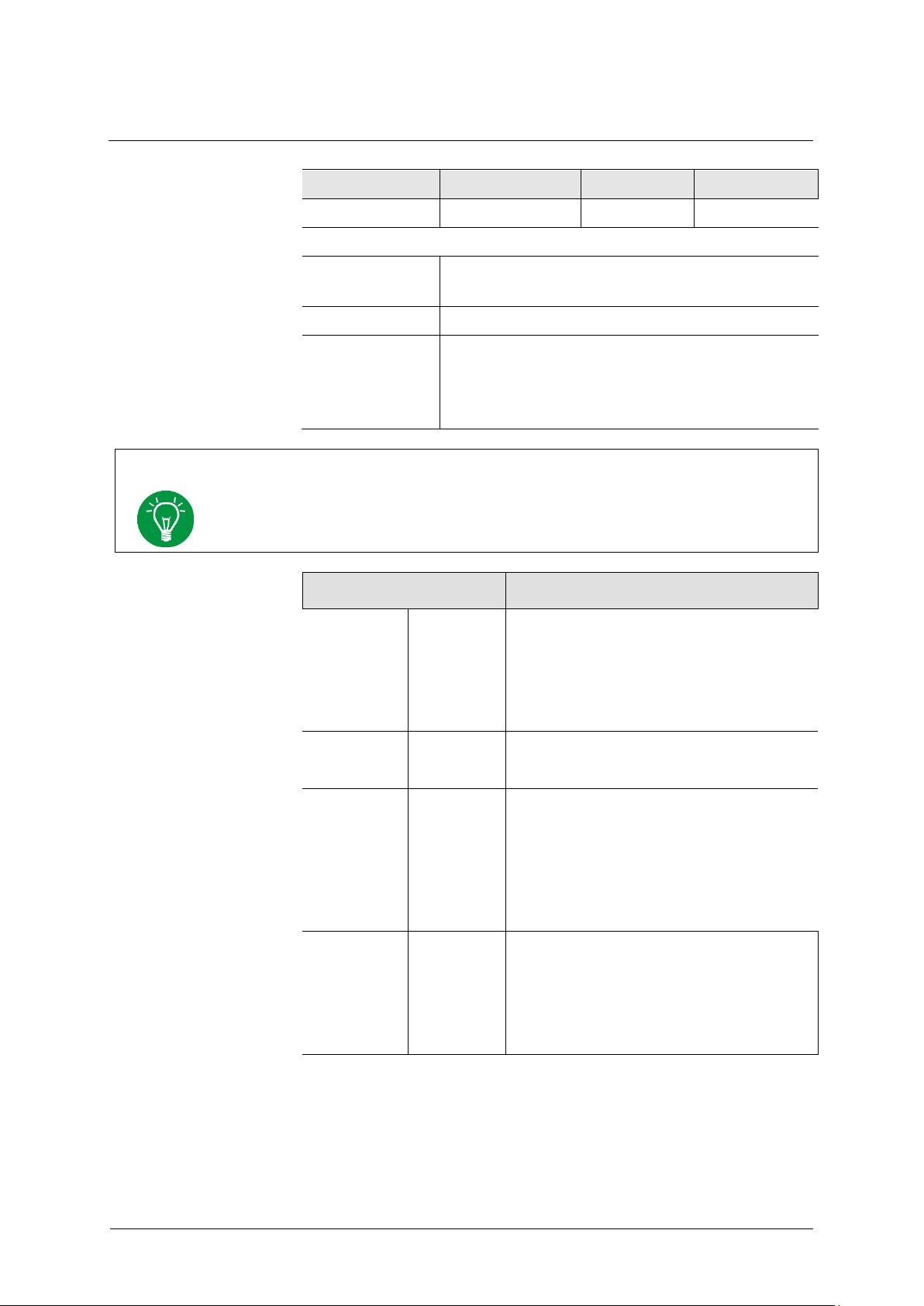
Measured value
Unit
Resolution
Display range
SpHb
g/dl
0.1
2 – 24.5
Curves
Curve
representation
P(t), V(t), V’(t), CO2(t), plethysmography
Loops
V(P), V’(V), V’(P)
Trends
Ppeak, Pplat, Pmean, PEEP, Vte, Vtspon, Vtleak,
MVe, MVespon, ftotal, fspon, O2, R, C, RSB, PTP,
EtCO2, Pulse, PVI, PI, SPO2, SPMet, SPCO, SPOC,
FiO2,Pplat/PEEP, MVe/MVespon, ftotal/fspon
NOTE
The EVE ventilator features a multi-computer design with mutual monitoring and
redundancy. In addition, ventilation pressures are limited by the hardware.
Parameter
Scale values
P (mbar)
[mbar]
−5/ 0/ +20/ +40/ +60/ +80/ +100
−5/ 0/ +15/ +30/ +45/ +60/ +75
−5/ 0/ +10/ +20/ +30/ +40/ +50
−5/ 0/ +5/ +10/ +15/ +20/ +25
t (s)
[s]
0/ 4/ 8/ 12/ 16/ 20 (adult and child)
0/ 2/ 4/ 6/ 8 (preterm infants and newborns)
V (ml)
[ml]
0/ 500/ 1000/ 1500/ 2000
0/ 250/ 500/ 750/ 1000
0/ 50/ 100/ 150/ 200
0/ 25/ 50/ 75/ 100
V' (l/min)
[l/min]
−200/ −100/ 0/ +100/ +200
−100/ −50/ 0/ +50/ +100
−50/ −25/ 0/ +25/ +50
−25/ −12.5/ 0/ +12.5/ +25
Auto-scaling
Page 29

®
1 General information
Fritz Stephan GmbH
GA-070T-0518V2.7-HAO-EN
29
Parameter
Unit
Lower limit
Upper limit
Resolution
PAW
mbar
2 – 59
11 – 60
1
PEEP
mbar
0 – 29
1 – 30
1
MVe
l/min
0.01 – 0.9
0.2 – 1.0
0.01
0.9 – 41
1.0 – 42
0.1 f 1/min
-
5 – 120/Off
1
Apnea
s 4 – 60
1
VT ml
0 – 99
1 – 100
1
99 – 495
100 – 500
5
490 – 990
500 – 2000
10
EtCO
2
Vol.%
0.0 – 11.9
0.1 – 12
0.1
mmHg
0 – 89
1 – 90
1
kPa
0.0 – 11.9
0.1 – 12
0.1
O2
Vol.%
18 – 99
22 – 100
1
SpO2
%
88 – 98
91 – 99/Off
1
Pulse
bpm
30 – 230
35 – 235/Off
1
PI %
0.03 – 0.1/Off
0.04 – 0.1
0.01
0.1 – 1
0.1 – 1
0.1
1 – 18
1 – 19/Off
1
PVI
%
1 – 97/Off
2 – 99/Off
1
SpMet
%
0.1 – 2/Off
1 – 2
0.1
2 – 99
2 – 99.5/Off
0.5
SpCO
%
1 – 97
2 – 98/Off
1
SpOC
ml O2/dl
1 – 33
2 – 34, Off
1
SpHb
g/dl 2 – 24.5
0.1
Alarms
Visual, acoustic, plain text message
Sound
Minimum setting
72 dB(A)
Maximum setting
80 dB(A)
Setting ranges
Alarm limit
Page 30

1 General information
30
GA-070T-0518V2.7-HAO-EN
Fritz Stephan GmbH
Flow/
volume
Flow sensor
Dead space
Children
2.7 ml
Adults
11 ml
Preterm infants and newborns
(PNT B)
0.6 ml
Proximal measurement of flow (pressure difference) and
pressure.
CO2
IRMA™ airway adapter
Dead space
Preterm infants and newborns
≤ 1 ml
Adults/children
≤ 6 ml
HME filter
Children
Air filter volume
8 ml
Connections
15f patient-side
15m machine-side
Luer lock
Pressure drop at
5 l/min
7.5 l/min
10 l/min
0.48 cmHO
0.63 cmH2O
0.78 cmHO
HME filter
Adults
Air filter volume
50 ml
Connections
22m/15f patient-side
22f/15m machine-side
Luer lock
Pressure drop at
50 l/min
0.2 kpa
O2 (EVETR)
Consumption-free measurement
Sensors
Page 31

®
1 General information
Fritz Stephan GmbH
GA-070T-0518V2.7-HAO-EN
31
Adult
emergency
1.8 m,
art. no.:
107061120
Compliance
1.05 ml/hPa
Insp. resistance (30 l/min)
0.0156 hPa/l/min
Insp. resistance (15 l/min)
0.0126 hPa/l/min
Insp. resistance (2.5 l/min)
0.008 hPa/l/min
Exp. resistance (30 l/min)
0.051 hPa/l/min
Exp. resistance (15 l/min)
0.0486 hPa/l/min
Exp. resistance (2.5 l/min)
0.064 hPa/l/min
Adult
emergency
2.4 m,
art. no.:
107061140
Compliance
1.48 ml/hPa
Insp. resistance (30 l/min)
0.0327 hPa/l/min
Insp. resistance (15 l/min)
0.022 hPa/l/min
Insp. resistance (2.5 l/min)
0.016 hPa/l/min
Exp. resistance (30 l/min)
0.06 hPa/l/min
Exp. resistance (15 l/min)
0.0743 hPa/l/min
Exp. resistance (2.5 l/min)
0.068 hPa/l/min
Adult
emergency
3 m,
art. no.:
107061141
Insp. compliance
1.88 ml/hPa
Insp. resistance (30 l/min)
0.0337 hPa/l/min
Insp. resistance (15 l/min)
0.0226 hPa/l/min
Exp. resistance (30 l/min)
0.053 hPa/l/min
Exp. resistance (15 l/min)
0.0633 hPa/l/min
Pediatrics
art. no.:
107061124
Compliance
1.03 ml/hPa
Insp. resistance (15 l/min)
0.116 hPa/l/min
Insp. resistance (2.5 l/min)
0.076 hPa/l/min
Exp. resistance (15 l/min)
0.12 hPa/l/min
Exp. resistance (2.5 l/min)
0.1 hPa/l/min
Single-use tube systems
Page 32

Page 33
®
2 Safety instructions
Fritz Stephan GmbH
GA-070T-0518V2.7-HAO-EN
33
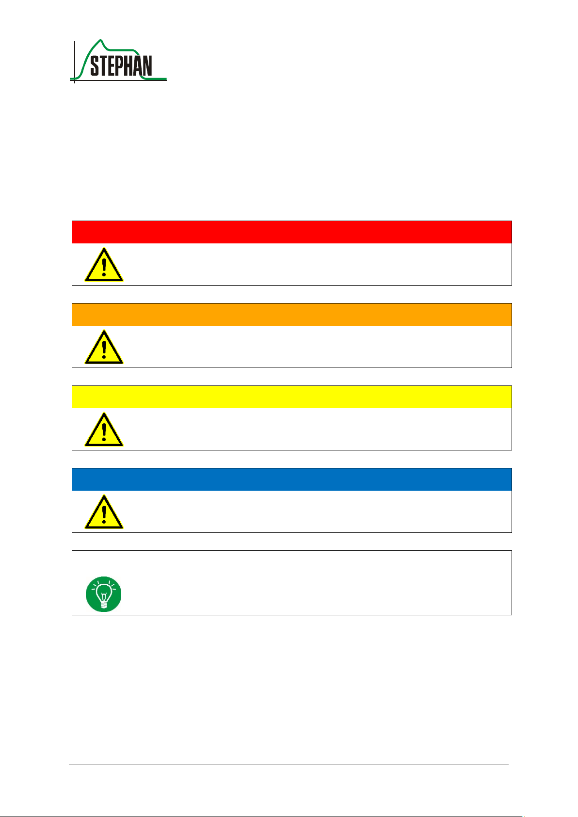
DANGER
Identifies potentially dangerous situations that result in death or life-threatening injury
if not avoided.
WARNING
Identifies potentially dangerous situations that may result in death or serious injury if
not avoided.
CAUTION
Identifies potentially dangerous situations that may result in minor or moderate injury
if not avoided.
ATTENTION
Identifies potentially dangerous situations that may result in minor or moderate injury
to the patient or user or damage to the medical device if not avoided.
NOTE
Identifies additional information that is useful for device operation and intended to
avoid problems during use.
2 Safety instructions
The following safety instructions are repeated at relevant points in the
operating manual and must be observed at all times.
Page 34
2 Safety instructions
34
GA-070T-0518V2.7-HAO-EN
Fritz Stephan GmbH
2.1 Danger
DANGER
The device must only be operated by authorized and properly trained professional
staff. The device must be operated according to the instructions in this operating
manual.
DANGER
The device is not certified for use in potentially explosive environments!
DANGER
The device must not be used in areas with contaminated air.
DANGER
Risk of explosion!
Do not use any combustible or anesthetic gases.
DANGER
Use of the device in the vicinity of magnetic resonance imaging systems may degrade
its functionality, which can potentially put the patient and operator at risk.
Page 35
®
2 Safety instructions
Fritz Stephan GmbH
GA-070T-0518V2.7-HAO-EN
35
2.2 Warning
WARNING
Lack of an alternative ventilation method, such as a self-priming operator-powered
resuscitator (according to ISO 10651-4), may result in patient death if the ventilator
fails. Always have a separate manual breathing bag handy.
WARNING
Only authorized customer service staff of FRITZ STEPHAN GMBH are permitted to
alter, modify, repair, or open the device, or to replace the internal battery. Only use
spare parts from FRITZ STEPHAN GMBH for maintenance.
WARNING
Do not operate the device outside the specified ambient conditions (see chapter 1.9).
Otherwise, device functionality may be impaired.
WARNING
The ventilator suctions ambient air to create compressed air. It must therefore never
be covered during operation or placed so that its operation or performance is impaired.
Failure to comply may result in device failure or damage and therefore pose a risk to
the patient.
WARNING
If the ventilator is to be operated with additional O2, the O2 supply pressure must be
2.8 – 6 bar (see chapter 1.9).
WARNING
The displayed O2 concentration is not a measurement. Instead, the gas concentration is
calculated from the flow rates.
Page 36
2 Safety instructions
36
GA-070T-0518V2.7-HAO-EN
Fritz Stephan GmbH
WARNING
Connecting a different type of gas instead of O2 (such as compressed air) will falsify
the displayed O2 concentration.
WARNING
Using the ventilator in a contaminated environment may be dangerous.
WARNING
Excessive ventilation modes can increase the temperature of the patient's breathing air
up to 43° C. Normal ambient temperatures counterbalance this effect.
WARNING
Only use patient tubing and accessories listed in chapters 1.2 (Product combination)
and 12 (List of accessories). Using other patient tubing or accessories not intended for
use with the ventilator may impair device performance and safety.
WARNING
When operating normally or in the event of the first fault, the tube system can be
contaminated with body fluids or exhaled gases by the ventilator up to the expiration
valve.
WARNING
Burns may be caused by antistatic or electro-conductive patient tubing when using
electrical high-frequency surgical instruments at the same time. Therefore, do not use
antistatic or electro-conductive patient tubing or lines.
WARNING
Never pull on patient tubing or electrical cables. This may cause the device to tip over
or drop.
Page 37
®
2 Safety instructions
Fritz Stephan GmbH
GA-070T-0518V2.7-HAO-EN
37
WARNING
Short-wave therapy devices, RF diathermy devices, defibrillators, and similar
equipment in close proximity of the device may impair device functionality. In such
cases, the patient and device must be monitored continuously.
WARNING
Never use the ventilator in a hyperbaric chamber.
WARNING
Never operate the ventilator with nitric oxide, helium, or mixtures containing helium.
WARNING
During non-invasive ventilation, a CO2 monitor for measuring the expiratory CO2
level must be used. The EVETR can be optionally equipped with an internal CO2
measuring unit. Otherwise, an external measuring unit must be used.
WARNING
During non-invasive ventilation, the exhaled volume may differ from the measured
exhaled volume if the mask is not fully sealed.
WARNING
FRITZ STEPHAN GMBH recommends using the pressure-controlled ventilation method
PC-CMV in the case of suction. To prevent the occurrence of negative pressures, the
PEEP must be set to a minimum of 4 mbar.
WARNING
Treat the individual parts carefully to avoid mechanical damage.
Only use correctly prepared parts to operate the device.
Page 38
2 Safety instructions
38
GA-070T-0518V2.7-HAO-EN
Fritz Stephan GmbH
WARNING
IEC 60601-1 and IEC 62353 must be observed specifically for medical devices with
an electrical connection. According to these directives, these devices must only be
repaired by the manufacturer or an entity explicitly authorized by the manufacturer for
this purpose.
WARNING
Check that no condensation accumulates near the Y piece of the inspiration tube
which could leak into the flow sensor.
WARNING
Make sure that there are no water droplets in the pressure measurement lines.
WARNING
After using the special alarm suppression state, make sure that the alarm is reactivated
before leaving the patient.
WARNING
FRITZ STEPHAN GMBH recommends that the ventilator is not operated with a low
battery (capacity <10%) because the device will switch off immediately in the event
of a power failure.
WARNING
Incorrectly selected trigger thresholds and large leaks may cause auto-triggering! In
this case, the trigger threshold has to be manually adjusted.
WARNING
When adding system components or sub-assemblies to the ventilation system of the
ventilator, the pressure gradient across the ventilation system, measured at the patient
connection port, may negatively affect the performance data of the ventilator.
Page 39
®
2 Safety instructions
Fritz Stephan GmbH
GA-070T-0518V2.7-HAO-EN
39
WARNING
The use of accessories, transducers, and cables other than those specified, with the
exception of transducers and cables sold by the manufacturer of the medical electrical
equipment or system as replacement parts for internal components, may result in
increased emission or decreased immunity of the medical electrical equipment or
system.
WARNING
Medical electrical equipment or systems should not be used adjacent to or stacked
with other equipment. If adjacent or stacked use is necessary, the medical electrical
equipment or system should be monitored to verify its intended operation in the
configuration in which it is used.
WARNING
No modifications to the EVETR are permitted without the manufacturer's
authorization!
Page 40

Page 41
®
3 Design and functional description
Fritz Stephan GmbH
GA-070T-0518V2.7-HAO-EN
41
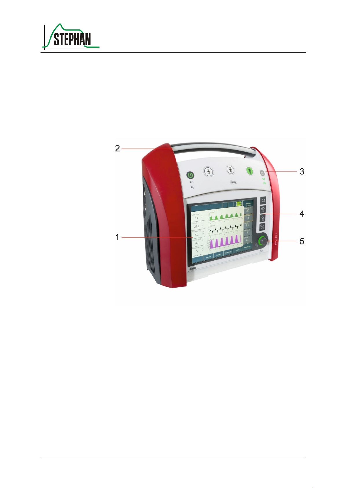
1 Touchscreen display
4 Function buttons
2 Transport handle with alarm
indicator
5 Control knob
3 Control panel
6 Removable display cover
3 Design and functional description
3.1 Front view
Fig. 1: Front view
Page 42

3 Design and functional description
42
GA-070T-0518V2.7-HAO-EN
Fritz Stephan GmbH
Fig. 2: Front view with display cover
3.1.1 Alarm indicator
The alarm indicator in the transport handle notifies the user about alarm
occurrences. It flashes yellow for medium priority alarms and red for
high priority alarms.
Page 43
®
3 Design and functional description
Fritz Stephan GmbH
GA-070T-0518V2.7-HAO-EN
43
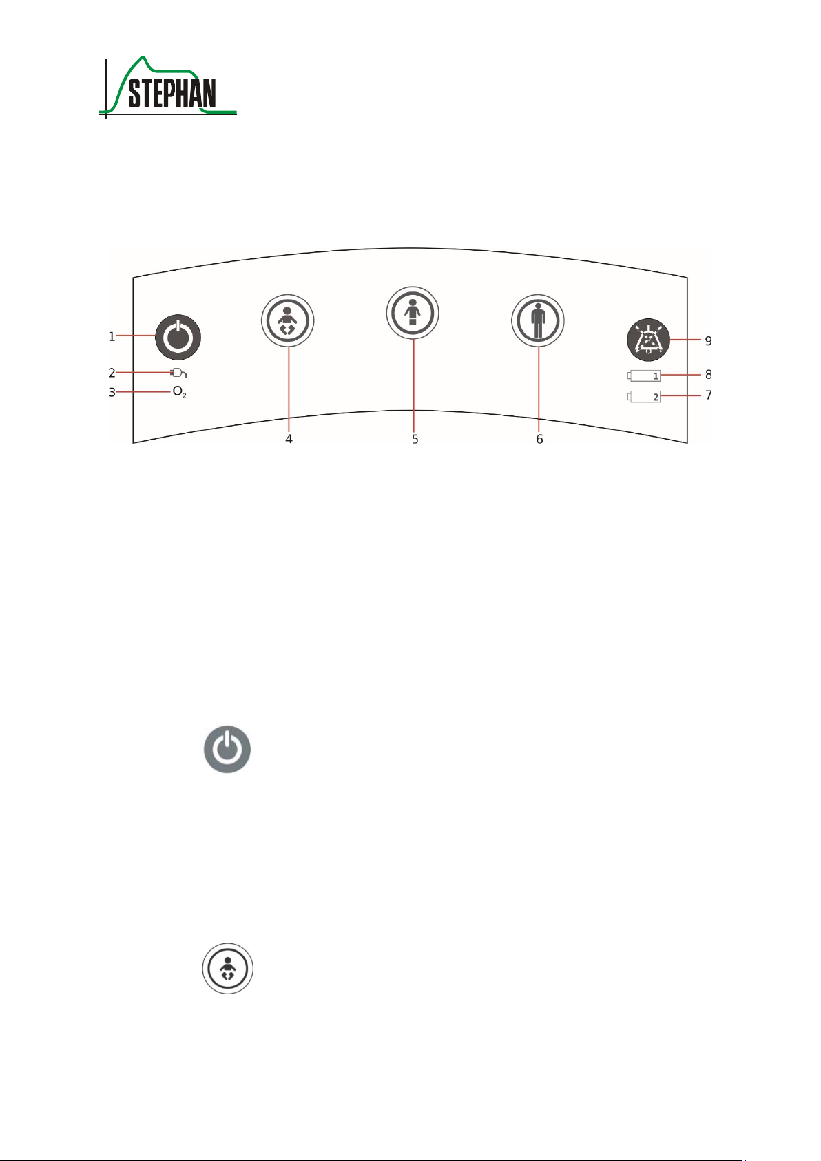
1 On/Off button
6 Adult fast tracking key
2 Mains power indicator
3 O2 supply indicator
7 Battery 2 charge indicator
4 Fast tracking key
Preterm infants and newborns
8 Battery 1 charge indicator
5 Child fast tracking key
9 Acoustic alarm suppression
On/Off/Standby button
Fast tracking keys
Fast tracking key for
preterm infants and
newborns
3.1.2 Control panel
Fig. 3: Control panel
Press this button to switch the EVETR on/off or, in the case of ongoing
ventilation, to switch it to Standby mode (see chapter 6.2).
To prevent operator errors, the desired fast tracking key must be pressed
for 0.5 s, after which it starts to flash green. Pressing the key again for
0.5 s will then start or switch to the selected ventilation mode.
Pressing this key will start ventilation using the standard parameters for
preterm infants and newborns (see chapter 6.6).
Page 44
3 Design and functional description
44
GA-070T-0518V2.7-HAO-EN
Fritz Stephan GmbH
NOTE
For safety reasons, the volume-controlled ventilation modes cannot be selected in the
mode for preterm infants and newborns.
NOTE
During therapeutic procedures, the acoustic alarm can be completely suppressed for
2 min by pressing the alarm suppression button before the occurrence of the first
alarm.
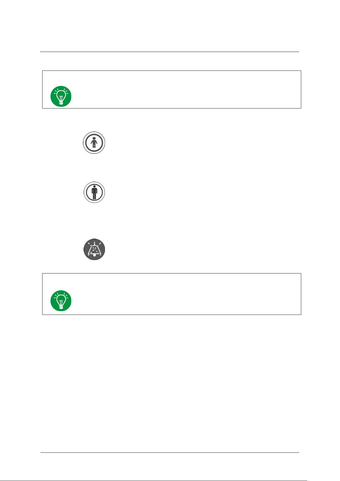
Child fast tracking key
Adult fast tracking key
Acoustic alarm
suppression
Pressing this key will start ventilation using the standard parameters for
children (see chapter 6.6).
Pressing this key will start ventilation using the standard parameters for
adults (see chapter 6.6).
Pressing this key will suppress acoustic alarms for 2 min. If the key is
pressed again within 5 s, the alarm suppression is canceled again.
Pressing the key again after 5 s has passed will start a new 2 minute
countdown.
Page 45

®
3 Design and functional description
Fritz Stephan GmbH
GA-070T-0518V2.7-HAO-EN
45
Green
Capacity between 75 – 100%
Yellow
Capacity between 40 – 74%
Red
Capacity between 1 – 39%
Flashing red
Capacity 0% or error
Green
Capacity between 75 – 100%
Yellow
Capacity between 40 – 74%
Red
Capacity between 1 – 39%
Flashing red
Capacity 0% or error
Battery 1
charge indicator
Battery 2
charge indicator
Mains power indicator
Oxygen supply
indicator
O
2
The charge indicator tells you the remaining capacity of the internal
battery 1.
The charge indicator tells you the remaining capacity of the external
battery 2 (optional).
When connected to the energy supply, the mains power indicator is green.
The internal batteries are charged automatically as needed. The battery
charge indicators tell you the current battery level.
The indicator is green when an oxygen cylinder with sufficient fill
pressure is connected.
Page 46
3 Design and functional description
46
GA-070T-0518V2.7-HAO-EN
Fritz Stephan GmbH
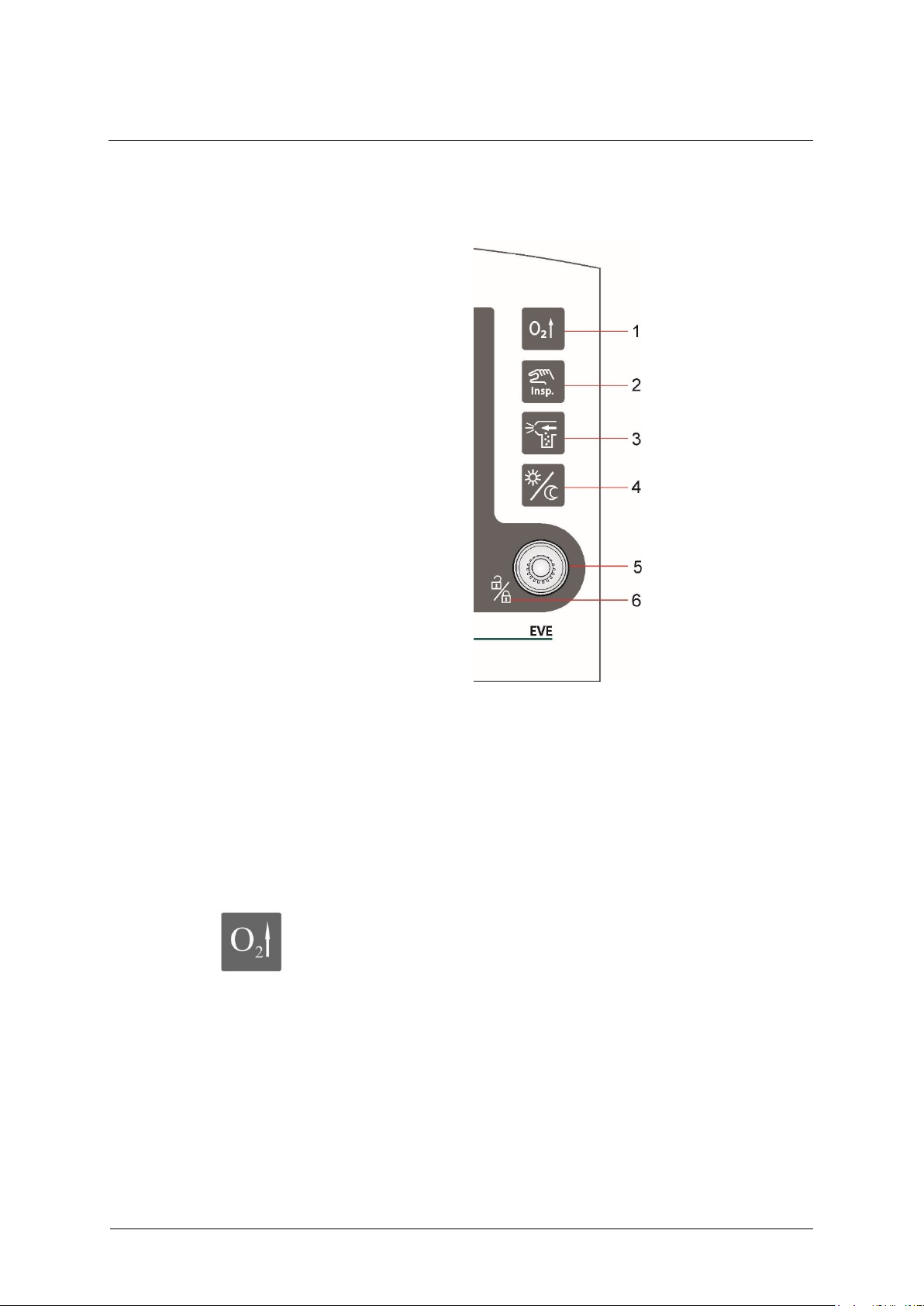
1 »Preoxy« button
4 »Day/Night« toggle button
2 »Inspiration Hold« button
5 Control knob
3 »Aerosol« button
6 Lock/unlock touchscreen
»Preoxy« button
3.1.3 Function buttons
Fig. 4: Function buttons
Press the »Preoxy« button to administer a pre-adjustable inspiratory
oxygen concentration for a certain preset interval. These settings can be
configured in the "System Settings/Function" menu (see chapter 4.1.4).
At the same time, the display for the set oxygen concentration changes to
the pre-set “Preoxy” value. The alarm limits for oxygen concentration are
adjusted automatically. The button is green while pre-oxygenation is in
progress.
Page 47
®
3 Design and functional description
Fritz Stephan GmbH
GA-070T-0518V2.7-HAO-EN
47
NOTE
This function is not available for the CPAP, VCV and PRVC ventilation modes. The
key is then not illuminated.
NOTE
Aerosol nebulization is only possible if O2 is connected to the ventilator.
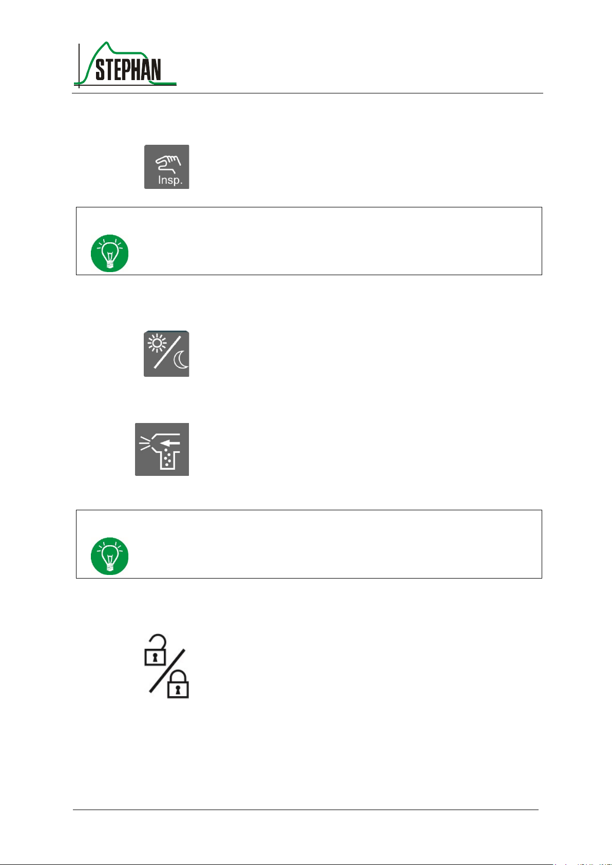
»Inspiration Hold«
button
»Day/Night« toggle
button
»Aerosol« button
Lock/unlock
touchscreen
Pressing this button during inspiration will hold inspiration at the end of
the normal inspiration phase for the duration for which the button is
pressed (maximum 15 s). Pressing the button during expiration will
trigger a mandatory inspiration using the set ventilation parameters.
This button lets you toggle the display, alarm indicator and
patient/function buttons between day and night mode.
Press the »Aerosol« button to switch on aerosol nebulization. The
medication nebulization duration can be set to between 5 and 30 min in
the "System Settings/Function" menu (see chapter 4.1.4). The
nebulization ends automatically at the end of the set time or when
pressing the button again. The button is green while nebulization is in
progress.
Pressing the control knob for three seconds will lock the touchscreen.
Press the control knob again for three seconds to unlock the touchscreen.
When you tap the locked touchscreen, a lock icon appears in the
"System Settings" field (see chapter 3.2.7).
Page 48

3 Design and functional description
48
GA-070T-0518V2.7-HAO-EN
Fritz Stephan GmbH
Control knob
Use the control knob to select and activate all indirect EVETR functions.
The control knob has the following functions:
Switching within the menus
Selecting and executing menu functions
Setting parameters
Confirming parameter settings
Turn the control knob clockwise or counterclockwise to scroll through
the available menus, function fields and parameter fields. You can also
use the touchscreen. When using the control knob for navigation, the field
in focus has an orange border. It can be selected using the touchscreen or
by pressing the control knob again. When changing a numeric parameter,
the control knob must be used to confirm this in order to accept the
modified value.
Page 49
®
3 Design and functional description
Fritz Stephan GmbH
GA-070T-0518V2.7-HAO-EN
49
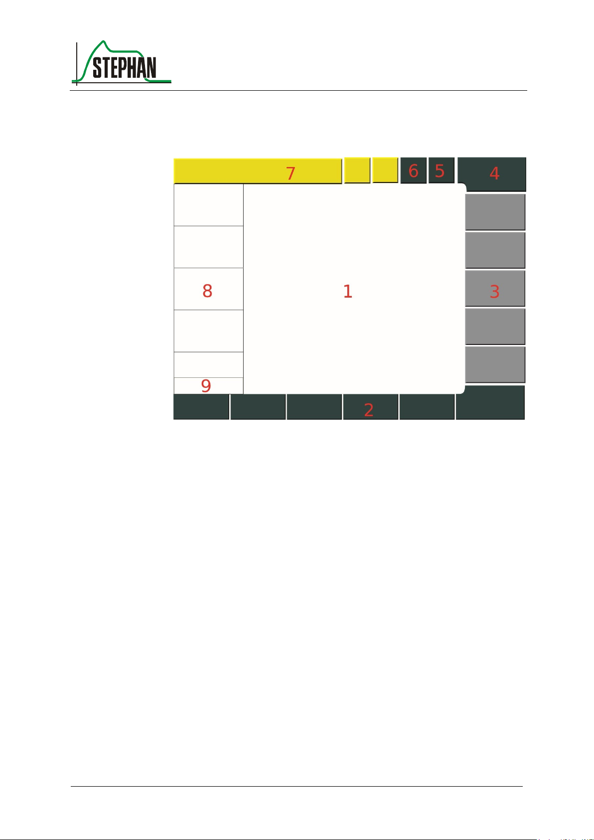
1 Graphic display,
adjust graphic display
7 Status/alarm indicators
and notifications,
Change to alarm limits,
preoxygenation, trigger
2 Function fields
3 Adjustable parameter display
4 Ventilation menu
(ventilation mode and flow sensor
display and selection)
8 Measurement value display
with alarm limits
5 System field
(Access system settings /
touchscreen lock state indicator)
9 Time display
6 System field
(Energy supply indicator)
3.2 Touchscreen monitor
Fig. 5: Monitor unit
Page 50
3 Design and functional description
50
GA-070T-0518V2.7-HAO-EN
Fritz Stephan GmbH
Setting the focus
Selection
3.2.1 General information about touchscreen navigation
The EVETR is controlled using a combination of touchscreen fields and
the control knob. Both the touchscreen and the control knob can be used
to select parameters or fields. When changing a numeric parameter, the
control knob must be used to confirm this in order to accept the modified
value.
Selecting a function field 3.2.1.1
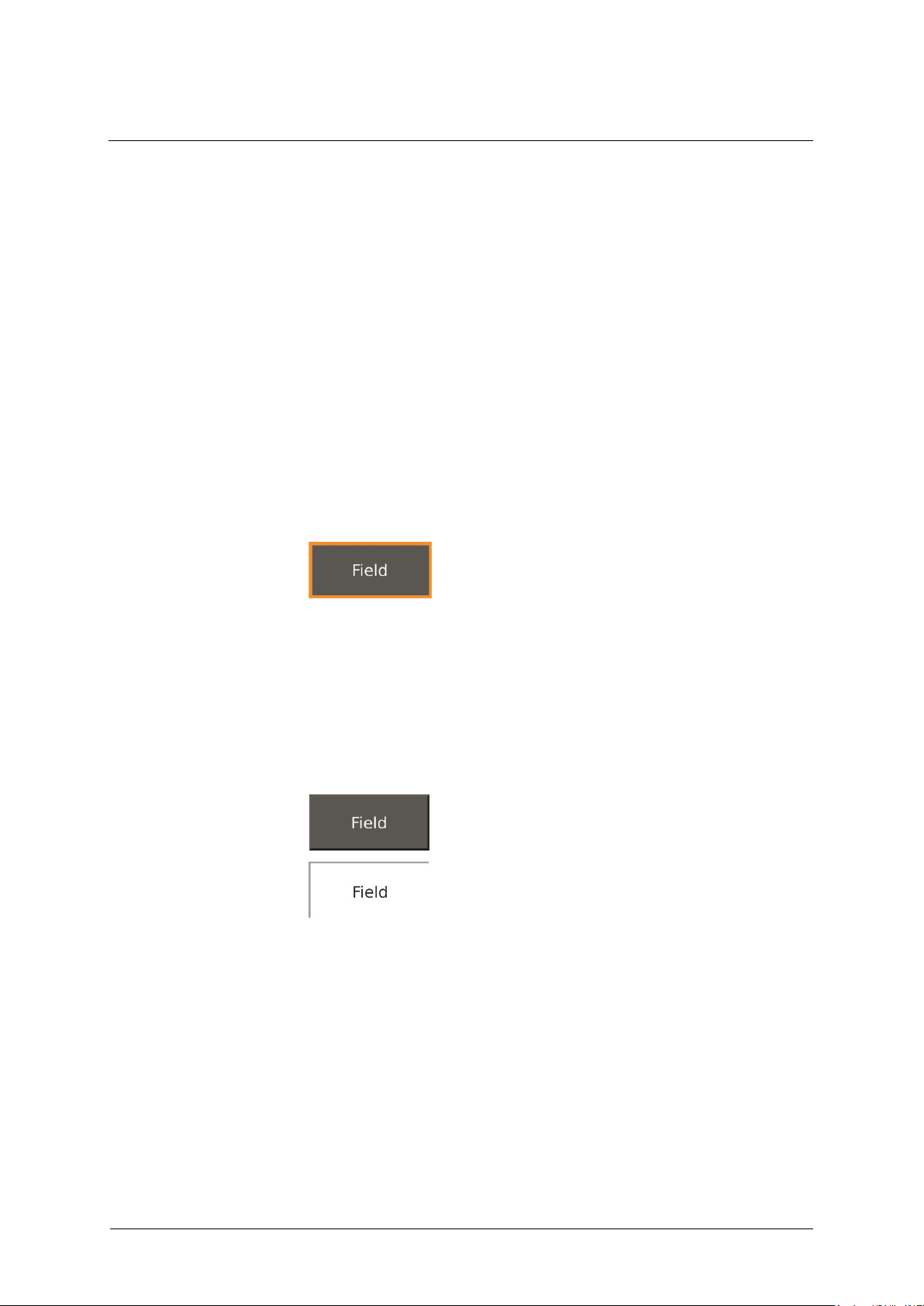
When navigating the display using the control knob, the focus is
indicated by an orange border. The field is "in focus" and can be selected
using the touchscreen or by pressing the control knob again.
Fig. 6: Focus
When selected, the color of a function field/tab changes from green to
white. In case of navigation, no further confirmation is necessary. For
safety-relevant functions (e.g. when changing the ventilation mode), a
second button appears for confirming the selection.
Fig. 7: Selecting a function field
Page 51
®
3 Design and functional description
Fritz Stephan GmbH
GA-070T-0518V2.7-HAO-EN
51
Options
Parameter
Setting options and parameters 3.2.1.2
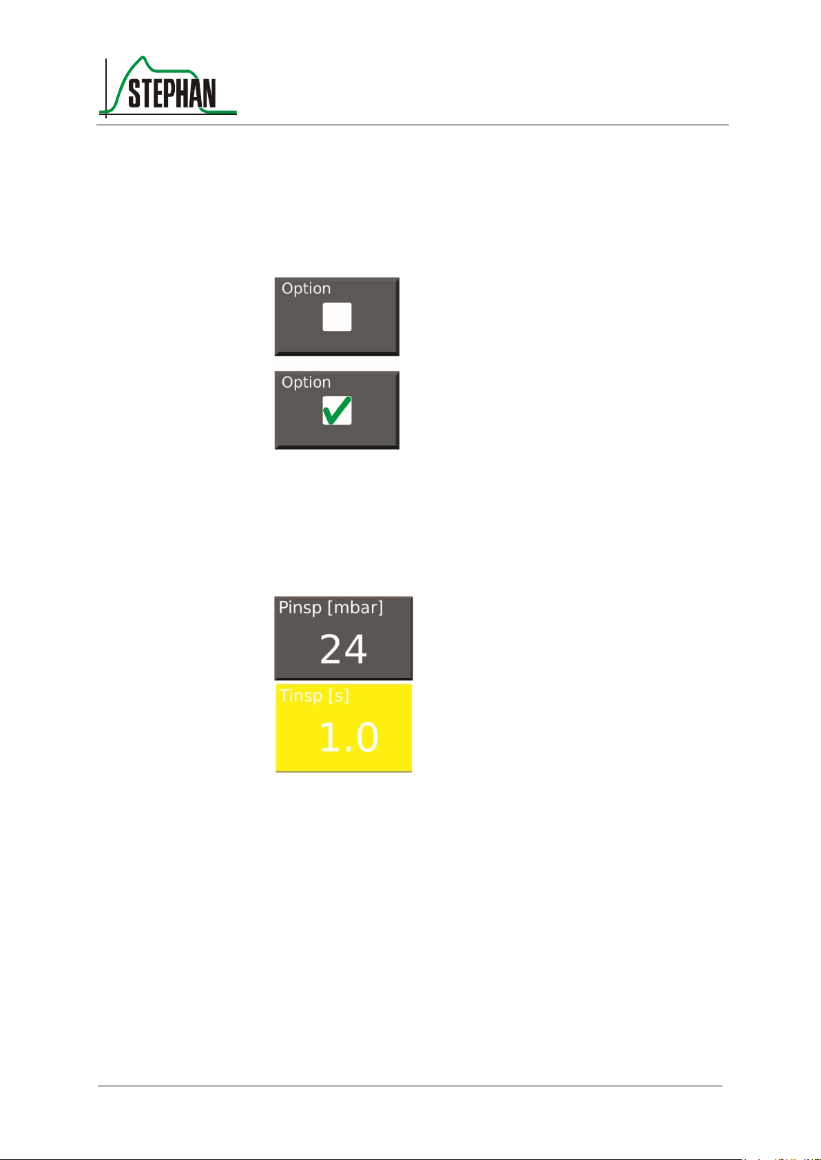
Pressing an option field places a green checkmark.
This will select the corresponding option.
Fig. 8: Option deselected/selected
Selecting a parameter field changes its color to yellow. The value can
now be changed using the control knob. Pressing the control knob again
will accept the value, and the field color changes back to gray.
Fig. 9: Changing values
Page 52
3 Design and functional description
52
GA-070T-0518V2.7-HAO-EN
Fritz Stephan GmbH
Return
Single drop-down box
Functions in the System Settings menu 3.2.1.3
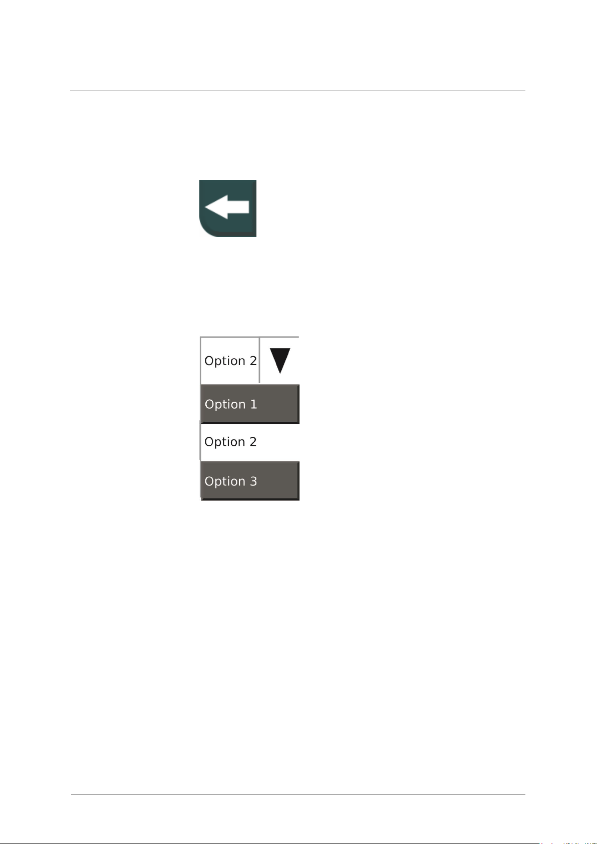
The "Return" field takes you to the higher menu level.
Fig. 10: "Return" field
Pressing a drop-down box opens a list of possible options below the box.
Use the control knob or touchscreen to make a selection.
Fig. 11: Single drop-down box
Page 53
®
3 Design and functional description
Fritz Stephan GmbH
GA-070T-0518V2.7-HAO-EN
53
NOTE
Except for the menu for setting the ventilation parameters (see chapter 3.2.3.6), a
menu can also be closed by selecting any other menu or a field on the touchscreen.
Multiple
drop-down box
Close
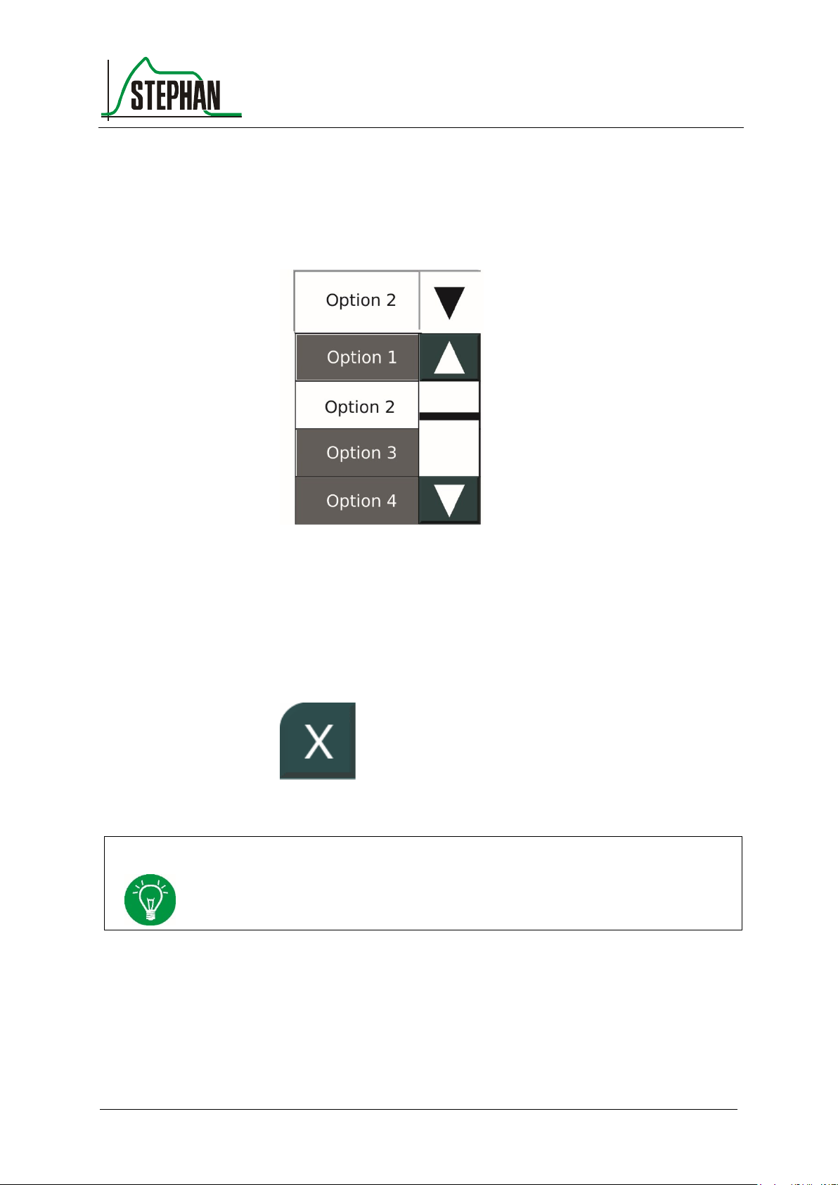
Pressing the multiple drop-down box opens multiple options below the
box. In addition, a navigation area opens on the right. Use the arrow
buttons to navigate the menu. The bar indicates the position within the
menu. Use the control knob or touchscreen to make a selection.
Fig. 12: Multiple drop-down box
Select the X field to close a menu window. This field is always located at
the top left corner of the open menu. If a parameter is selected and
modified, but not yet confirmed when pressing this field, the action is
canceled. The change is discarded.
Fig. 13: "Close" field
Page 54
3 Design and functional description
54
GA-070T-0518V2.7-HAO-EN
Fritz Stephan GmbH
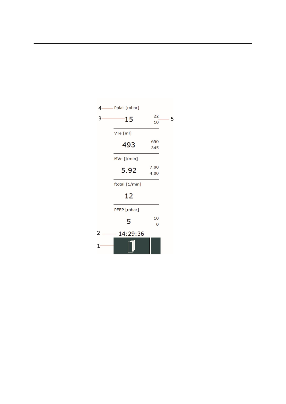
1 Function field for toggling
between the measured value
display and the display of the
active measured value block
4 Name of measured value
including unit
2 Time display
5 Alarm limits display
3 Measured value
3.2.2 Measured value display
This display gives a quick view of the relevant measured values together
with the alarm limits shown after the measured value.
Fig. 14: Measured value display
Five measured values are displayed. Three sets of 5 measured values each
are available. Only one set can be displayed at a time. Use the function
field to switch between the sets (see chapter 3.2.3.1).
Page 55

®
3 Design and functional description
Fritz Stephan GmbH
GA-070T-0518V2.7-HAO-EN
55
Item
Set 1
Set 2
Set 3
1
Pplat
(cannot be configured)
O2
Pmean
2
VTe
VTe
VTe
3
MVe
EtCO2
VTespon
4
ftotal
SpO2
Ppeak
5
PEEP
Pulse
VTleak
Category
Measured value
Description
Unit
Pressure
Ppeak
Inspiratory peak pressure
mbar
Pplat
Plateau pressure
mbar
Pmean
Mean airway pressure
mbar
PEEP
Positive end expiratory pressure
mbar
Volume
MVe
Expiratory respiratory minute volume
l/min
MVespon
Spontaneous expiratory respiratory minute volume
l/min
VTe
Expiratory tidal volume
ml
VTespon
Spontaneous expiratory tidal volume
ml
VTleak
Leak
ml
Flow
V´min
Minimum flow
l/min
V´max
Maximum flow
l/min
Time
Tinsp
Inspiration time
s
Texp
Expiration
s
ftotal
Total respiratory rate
(mechanical + spontaneous respiratory rate)
1/min
fspon
Spontaneous respiratory rate
1/min
I:E
Inspiration time ratio
-
Tab. 4: Basic configuration of the measured value indicator's three sets
With the exception of Pplat, the user can freely configure the type and
sort order of measured values in the three sets in the control panel
(see chapter 4.3.1). The measured values listed in the following table are
determined by the ventilator and can be displayed:
Page 56
3 Design and functional description
56
GA-070T-0518V2.7-HAO-EN
Fritz Stephan GmbH
Category
Measured value
Description
Unit
Gas
O2
Inspiratory oxygen concentration
%
EtCO2
End expiratory CO2 concentration
mmHg/kPa/
Vol.%
Diagnostic
R
Patient and tube resistance
mbar l/s
C
Patient compliance
ml / mbar
P0.1
Oral occlusion pressure after 100 ms
mbar
PTP
Pressure time product
mbar x s
Time constant
Product from resistance and compliance
s
RSB
Quotient from frequency and VT
(Rapid shallow breathing index)
1/min*l
Masimo
SpO2
Oxygen saturation
%
Pulse
bpm
PI
Perfusion index
%
PVI
Pleth Variability Index
%
SpMet
Methemoglobin
%
SpCO
Carboxyhemoglobin
%
Alarm limits
Tab. 5: Measured values
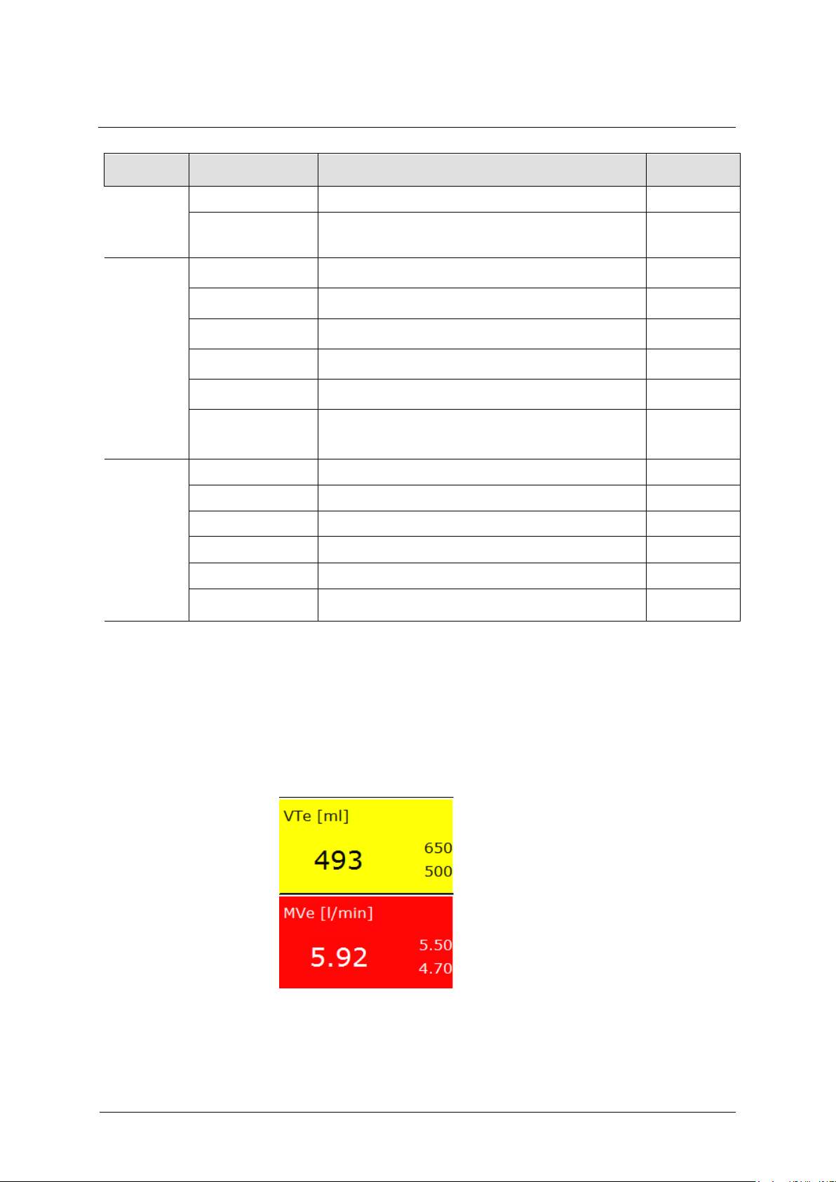
If a value breaches the upper or lower active alarm limit, the corresponding
field is highlighted in red (HP alarm) or yellow (MP alarm), depending
on the alarm priority. In addition, an error message appears in the status,
alarm, and info display.
Fig. 15: Color change when alarm limits are breached
Page 57
®
3 Design and functional description
Fritz Stephan GmbH
GA-070T-0518V2.7-HAO-EN
57
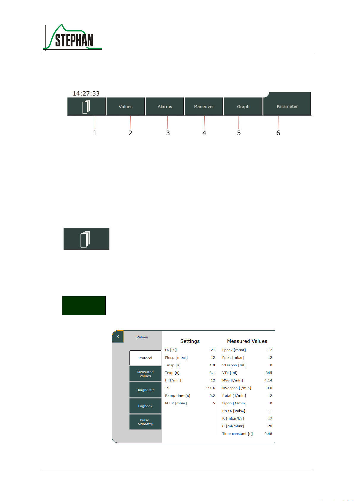
1 Measured value indicator switch
4 Maneuver
2 Values
5 Graphs
3 Alarms
6 Parameters
Values
3.2.3 Function fields
Fig. 16: Function fields
Measured value indicator switch 3.2.3.1
Pressing this function field toggles between the three sets of measured
values (see chapter 3.2.2). The active set is indicated by a number in the
function field.
Values 3.2.3.2
Pressing this function field opens the "Values" sub-menu. This provides
an overview of the measured values currently determined by the
ventilator.
Fig. 17: Values sub-menu
Page 58

3 Design and functional description
58
GA-070T-0518V2.7-HAO-EN
Fritz Stephan GmbH
NOTE
The logbook data can be saved on the internal SD card (see chapter 4.4.9).
Logbook
The various measured values can be viewed by selecting the »Protocol«,
»Measured Values«, and »Pulse oximetry« fields.
The following data is automatically archived in the logbook with the
associated time in hours and minutes. This data can be viewed by
selecting the »Logbook« field.
The following events are saved:
Start / Stop/Standby
Settings and change to the settings
Execution of special actions and maneuvers
Occurring alarms (ON/OFF)
The last 1000 values can be displayed on the monitor. In total up to
1100 entries can be saved in the device. If this value is exceeded, the
oldest entries are automatically overwritten.
Page 59
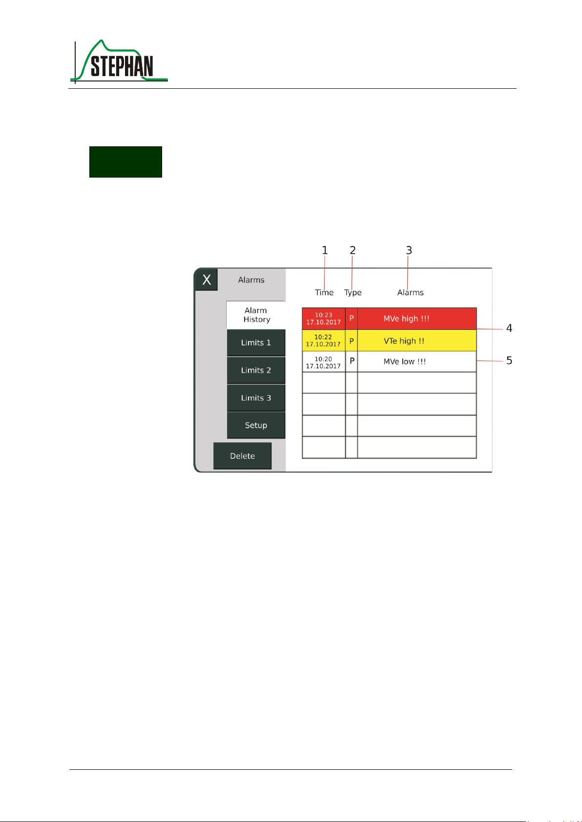
®
3 Design and functional description
Fritz Stephan GmbH
GA-070T-0518V2.7-HAO-EN
59
1 Time and date when the alarm
occurred
3 Alarm text
4 Active alarms
2 Alarm category
5 Inactive alarm
Alarms
Alarm history
Alarms 3.2.3.3
The "Alarms" sub-menu shows the »Alarm History« and all measured
values that are monitored by alarm limits.
Pressing the »Alarm History« field or the alarm indicator
(see chapter 3.2.8) opens a list of the seven most recent alarms.
Fig. 18: "Alarm History" sub-menu
The system shows the date and time when the alarm occurred, the
category (P = patient alarm, T = technical alarm), and the alarm text.
The color indicates the priority (red = HP alarm; yellow = MP alarm;
white = alarm no longer active).
All active and inactive alarms are stored internally. However, the alarm
history only shows the 7 most recent alarms in chronological order. Once
the cause of the alarm has been eliminated, the message remains, but is
no longer highlighted in color. If an inactive alarm recurs, it becomes
current and appears in the alarm history.
Manually deleting an inactive alarm from the alarm history moves the
next internally stored alarm into the on-screen alarm history.
Page 60
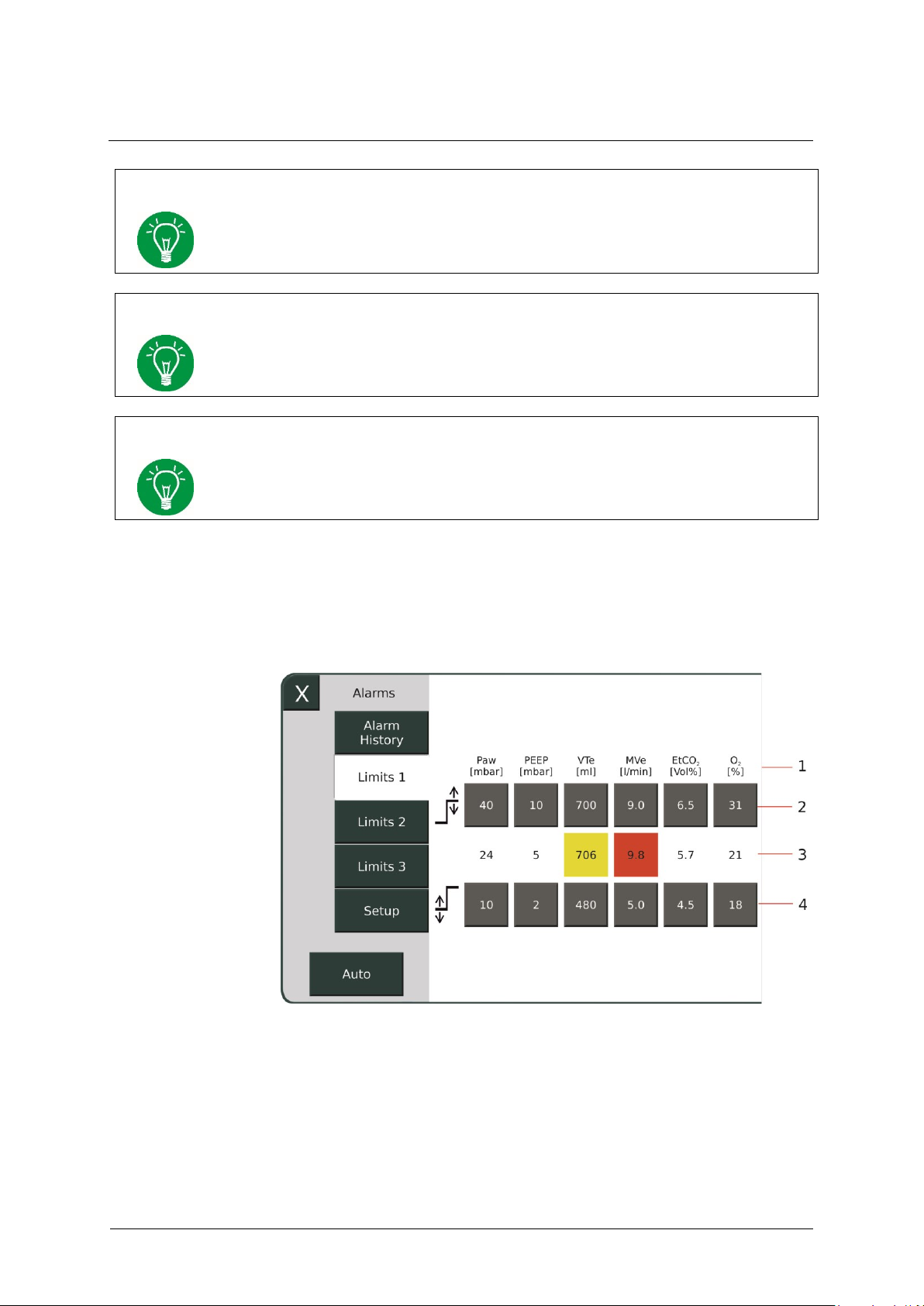
3 Design and functional description
60
GA-070T-0518V2.7-HAO-EN
Fritz Stephan GmbH
NOTE
Switching off the device completely will automatically delete all entries from the
alarm history.
NOTE
The alarm history is retained in the event of a power outage of less than 30 s. In this
case, energy is supplied by the internal battery.
NOTE
In case of a total power failure, all entries are deleted from the alarm history.
1 Name and unit
3 Current measured value
2 Upper limit
4 Lower limit
Limits
Pressing the »Limits 1-3« fields lets you view all the alarm limits and
adjust them to the patient's needs. If limits are breached during the
current ventilation, the corresponding parameter field turns yellow or red,
depending on the alarm priority.
Fig. 19: Alarms sub-menu
Page 61

®
3 Design and functional description
Fritz Stephan GmbH
GA-070T-0518V2.7-HAO-EN
61
WARNING
The alarm limits must be verified by medical personnel and possibly adapted to the
current patient situation. The alarm limits must always be based on the patient's needs.
Using extreme settings that are not medically indicated may render the alarm system
useless and put the patient at risk.
Parameter
Unit
Lower limit
Upper limit
PAW
mbar
-
Pinsp+10
(maximum 60 mbar)
PEEP
mbar
Set value -2-
Set value + 2
VTe
(VC mode)
ml
Set value
VT −30%
Set value
VT +30%
VTe
(PC mode)
ml
Adult:
350
Adult:
650
Child:
140
Child:
260
Preterm infants
and newborns:
14
Preterm infants and
newborns:
26
MVe
(VC mode)
ml
(Set values VT·f)
−30%
(Set values VT·f)
+30%
MVe
(PC mode)
ml
Adult:
4.2
Adult:
7.8
Child:
2.8
Child:
5.2
Preterm infants
and newborns:
0.42
Preterm infants and
newborns:
0.78
fspon
1/min
-
50
Apnea
s - 15
EtCO2
mmHg
Vol.%
kPa
30
4
4
45
6
6
O2
%
Set value −10%
minimum
21%
Set value +10%
maximum 100%
The EVETR always starts with the following preset alarm limits:
Tab. 6: Preset alarm limits
Page 62

3 Design and functional description
62
GA-070T-0518V2.7-HAO-EN
Fritz Stephan GmbH
Parameter
Unit
Lower limit
Upper limit
Resolution
PAW
mbar
-
11 – 60
1
PEEP
mbar
0 – 29
1 – 30
1
VTe ml
0 – 100
1 – 100
1
100 – 490
100 – 500
5
490 – 990
500 – 2000
10
EtCO
2
Vol.%
0.0 – 11.9
0.1 – 12.0
0.1
mmHg
0 – 89
1 – 90
1
kPa
0 – 11.9
0.1 – 12.0
0.1
PI %
Off,
0.03 – 0.1
0.04 – 0.1
0.01
0.1 – 1
0.1 – 1
0.1
1 – 18
1 – 19, Off
1
PVI
%
1 – 98/Off
2 – 99/Off
1
SpO2
%
88 – 98
91 – 99/Off
1
SpCO
%
1 – 97
2 – 98/Off
1
fspon
1/min
5 – 120/Off
1
Apnea
s 4 – 60
1
Pulse
bpm
30 – 230
35 – 235/Off
1
Changing alarm limits
Auto
To change the alarm limits, select the corresponding upper or lower limit
on the touchscreen. The field opens and is illuminated yellow. Use the
control knob to adjust the value within the preset limits.
Tab. 7: Adjustable alarm limits
Pressing the »Auto« field sets the PAW, MVe, VTe, EtCO2 and PEEP
limits to the system's automatic alarm limit presets.
Page 63

®
3 Design and functional description
Fritz Stephan GmbH
GA-070T-0518V2.7-HAO-EN
63
Parameter
Unit
Lower limit
Upper limit
PAW
(VC mode)
mbar
-
Pplat+10 measurement
value
maximum 35 mbar, no
less than PEEP+5
PAW
(PC mode)
mbar
-
Pinsp + 10
maximum 35 mbar
PAW
(PC mode+PRVC)
mbar
No Auto button
available
No Auto button
available
PEEP
mbar
Set value -2-
Set value + 2
VTe
mbar
−30%
+30%
EtCO2
mbar
−10%
minimum
35 mmHg
+10%
maximum
45 mmHg
Parameter
Unit
Lower limit
Upper limit
O2 % Set value −10
minimum 21%
Set value +10
maximum 100%
PEEP
mbar
-
Set value + 5
Tab. 8: Automatic alarm limits
If configured in the setup menu, the alarm limits for FiO2, PAW LOW
and PEEP are always set automatically.
Page 64
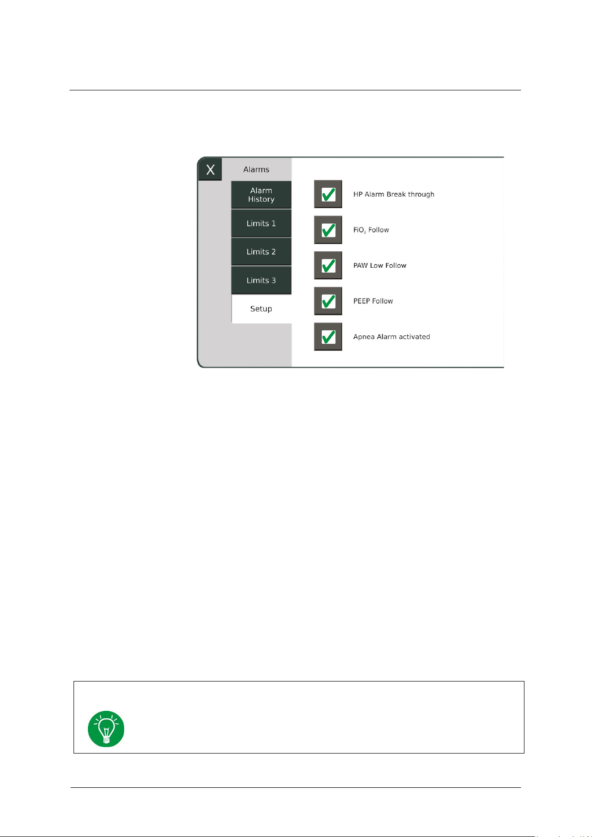
3 Design and functional description
64
GA-070T-0518V2.7-HAO-EN
Fritz Stephan GmbH
NOTE
The settings are automatically saved when shutting down the device and are retained
when restarting the device. When the mainboard software is updated, all settings in
the menu are reset and may need to be manually reactivated.
Setup
HP Alarm Break
through
"PAW Low Follow"
"FiO2 Follow"
PEEP Follow"
You configure certain alarm settings in this menu.
Fig. 20: Alarms/Setup sub-menu
If the "HP Alarm Break through" option is activated, an acoustic
alarming of all HP alarms occurs even if acoustic alarm suppression is
switched on.
If you activate the "PAW Low Follow" option, the lower PAW alarm
limit is automatically updated. However, it can also be manually set. If
you deactivate this function, it is only possible to make the setting
manually.
If you activate the "FiO2 Follow" option, the FiO2 alarm limits are
automatically updated. However, they can also be manually set. If you
deactivate this function, it is only possible to make the setting manually.
If the "PEEP Follow" option is activated, the PEEP alarm limits are
automatically updated. You can also set them manually. If you deactivate
this function, it is only possible to make the setting manually.
Page 65
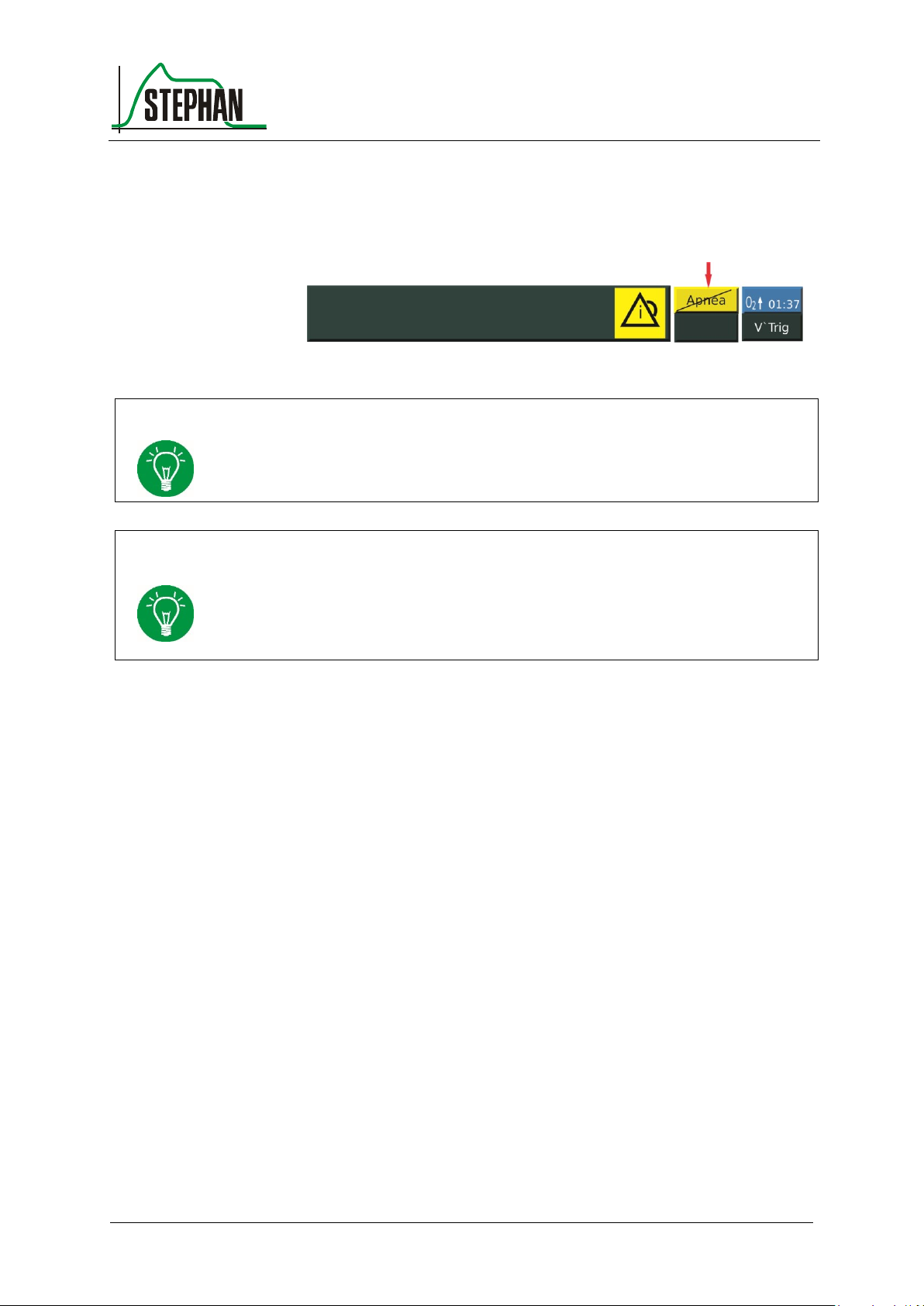
®
3 Design and functional description
Fritz Stephan GmbH
GA-070T-0518V2.7-HAO-EN
65
NOTE
The "Apnea alarm deactivated" symbol is only displayed if alarm suppression is not
activated.
NOTE
The "Apnea alarm activated" setting switches on each time the device is started and
cannot be saved as the default value. Fritz Stephan GmbH recommends
supplementing patient monitoring with external monitoring if the apnea alarm is
deactivated.
"Apnea alarm
activated"
If the "Apnea alarm activated" option is selected, the device displays the
apnea alarm. If the option is deactivated, the system does not issue an
apnea alarm. The "Apnea alarm deactivated" icon is then displayed in the
status, alarm, and info display (see chapter 3.2.8).
Fig. 21: Status, alarm, and info display, "Apnea alarm deactivated"
Page 66
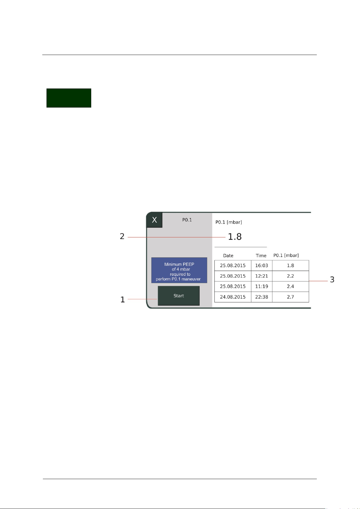
3 Design and functional description
66
GA-070T-0518V2.7-HAO-EN
Fritz Stephan GmbH
1 »Start« field
3 Measured value history
2 Current measured value
Maneuver
P0.1 maneuver
Maneuver 3.2.3.4
This sub-menu lets you perform the following maneuvers.
P0.1
SpHb measurement
To start a maneuver, select and press the corresponding field. This opens
a sub-menu listing the main parameters. Press the »Start« field to trigger
the maneuver. The following section provides a brief description and
explanation of the various maneuvers:
The respiratory tract occlusion pressure (P0.1) is a measured parameter of
the patient's respiratory drive. It is an index for the inspiration breathing
effort by the patient against a closed system in the first 100 ms.
Fig. 22: Maneuver P0.1
A PEEP of minimum 4 mbar must be present for measurement of the
P0.1 value. Then select the »Start« field. At the patient's next inspiration,
EVE now automatically detects the spontaneous breathing effort by the
patient, closes the system and measures the P0.1 value. When the
measurement is complete, the determined value appears in the display.
The three most recent measured values are saved and displayed for
reference purposes.
Page 67
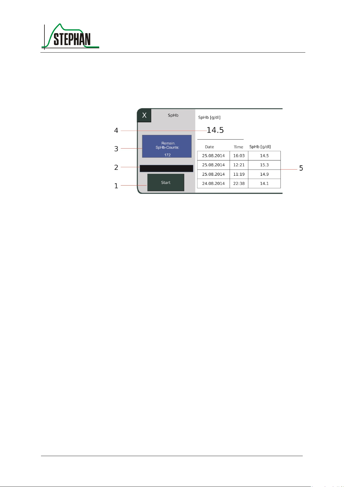
®
3 Design and functional description
Fritz Stephan GmbH
GA-070T-0518V2.7-HAO-EN
67
1 »Start« field
4 Current measured value
2 Bar graph
5 Measured value history
3 Remaining SpHb measurements
SpHb measurement
This lets you measure a single hemoglobin value. This allows early
detection of possible internal patient bleeding without having to wait for
lab results.
Fig. 23: SpHb measurement
The sensor requires a brief warm-up phase, indicated by the black bar
graph. When the bar graph is completely filled, the SpHb measurement
can be performed by pressing the »Start« field. When the measurement is
complete, the measured value appears on the display. The three most
recent measured values are saved and displayed for reference purposes.
Page 68
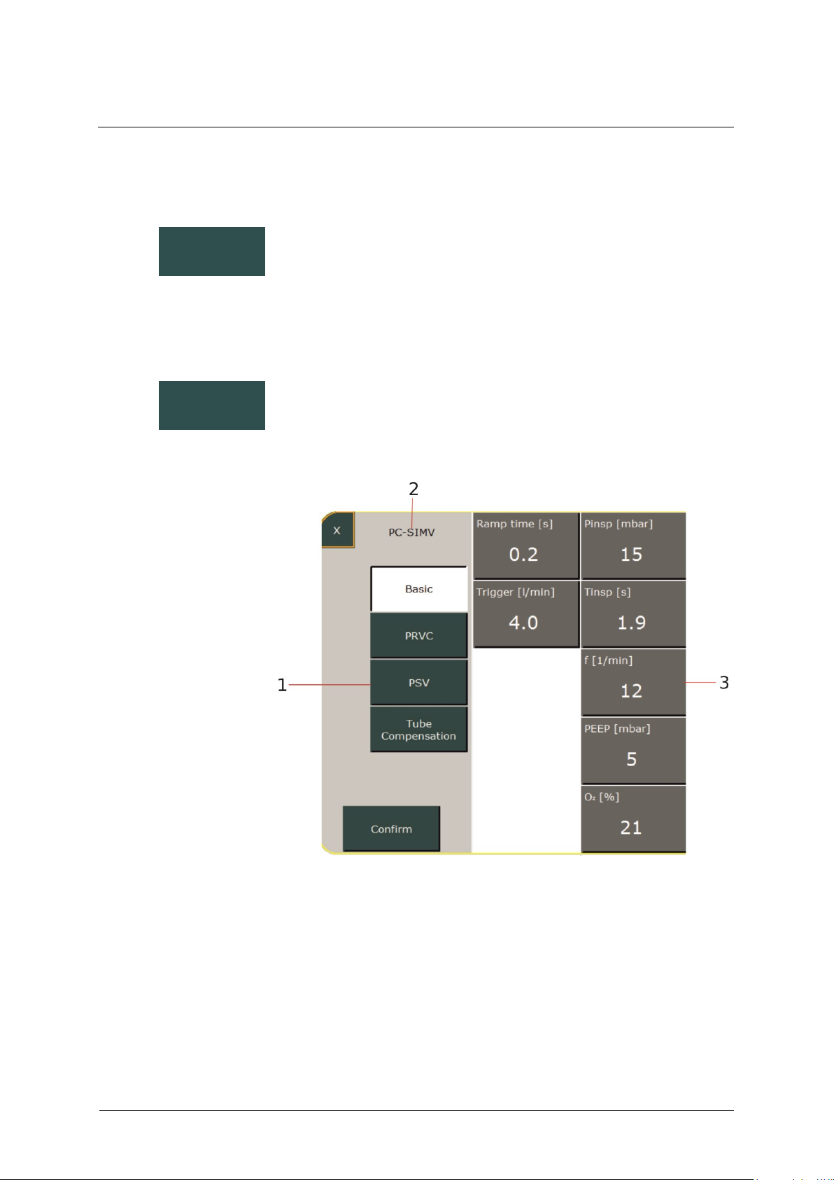
3 Design and functional description
68
GA-070T-0518V2.7-HAO-EN
Fritz Stephan GmbH
1 Optionally selectable
additional functions for the
ventilation mode
2 Current ventilation mode
indicator
3 Ventilation parameters
Graph
Parameter
Graph 3.2.3.5
The "Graph" sub-menu lets you configure the appearance of the graphic
display (see chapter 3.2.9).
Parameter 3.2.3.6
Pressing this function field opens a sub-menu with all configurable
parameters and additional functions for the currently active ventilation
mode.
Fig. 24: Configurable parameters for standard SIMV ventilation
Page 69
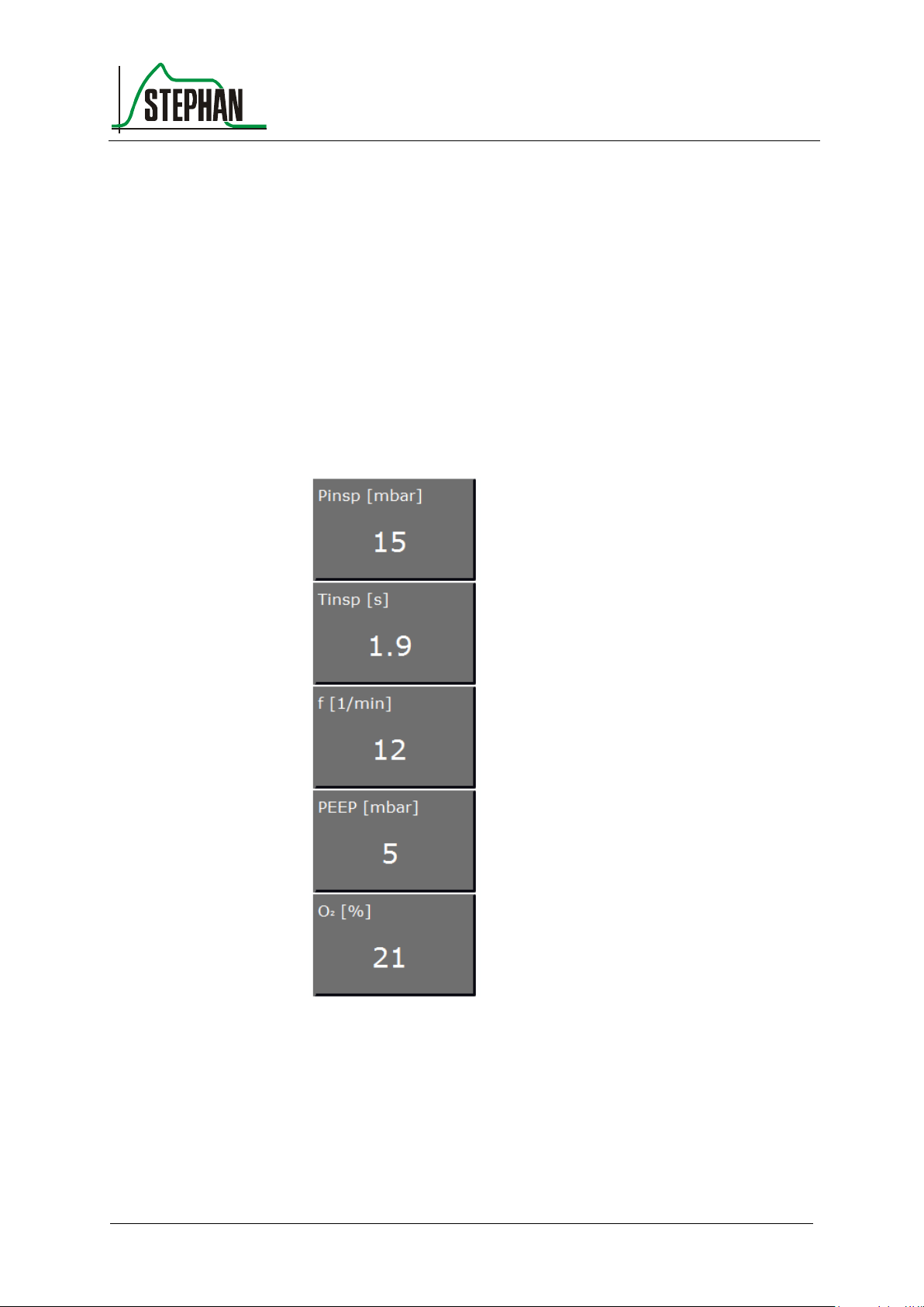
®
3 Design and functional description
Fritz Stephan GmbH
GA-070T-0518V2.7-HAO-EN
69
To change a parameter, select the corresponding field. The field then
turns yellow. You can now change the value using the control knob.
If additional functions exist for the currently active ventilation mode,
these can also be activated from this menu. Press the »Confirm« field to
save the new settings and close the sub-menu.
3.2.4 Parameter display
The display provides an overview of the five most important ventilation
parameters for the currently active ventilation mode.
Fig. 25: Parameter display for PC-CMV ventilation mode
To change a parameter, select the corresponding field. The field then
turns yellow. You can now change the value using the control knob.
Page 70
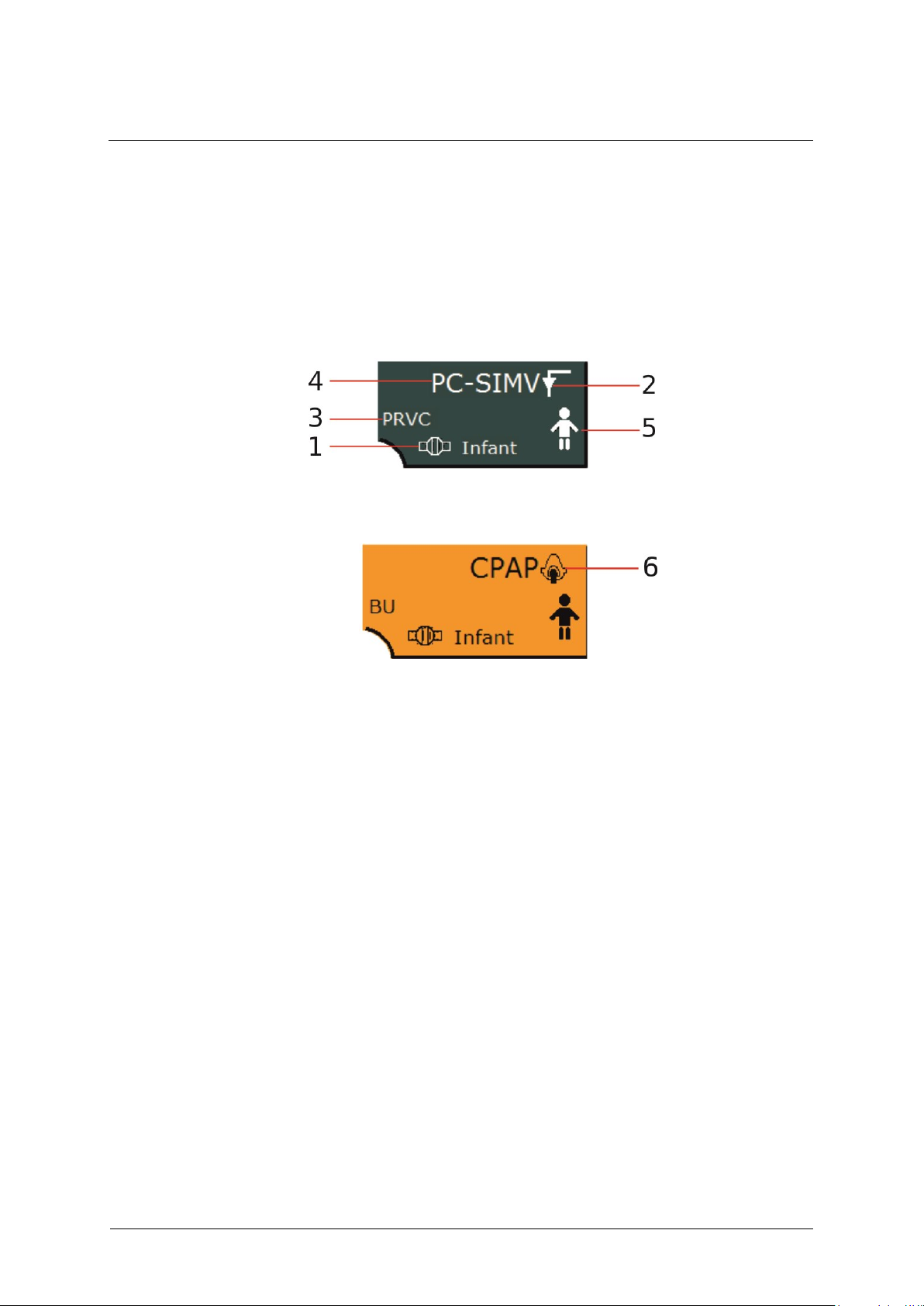
3 Design and functional description
70
GA-070T-0518V2.7-HAO-EN
Fritz Stephan GmbH
1 Flow sensor type
4 Ventilation mode
2 Icon for invasive ventilation
5 Patient type
3 Additional function for
ventilation mode
6 Icon for non-invasive
ventilation
3.2.5 Ventilation mode display
This display indicates the current ventilation mode, the active additional
functions, the patient type and the flow sensor type. Selecting a noninvasive ventilation mode causes the display to turn orange. In addition,
the icon for non-invasive ventilation appears.
Fig. 26: Invasive ventilation mode
Fig. 27: Non-invasive ventilation
Selecting this field opens a ventilation menu (see chapter 6.8) where you
can adjust the settings to the current ventilation scenario.
Page 71
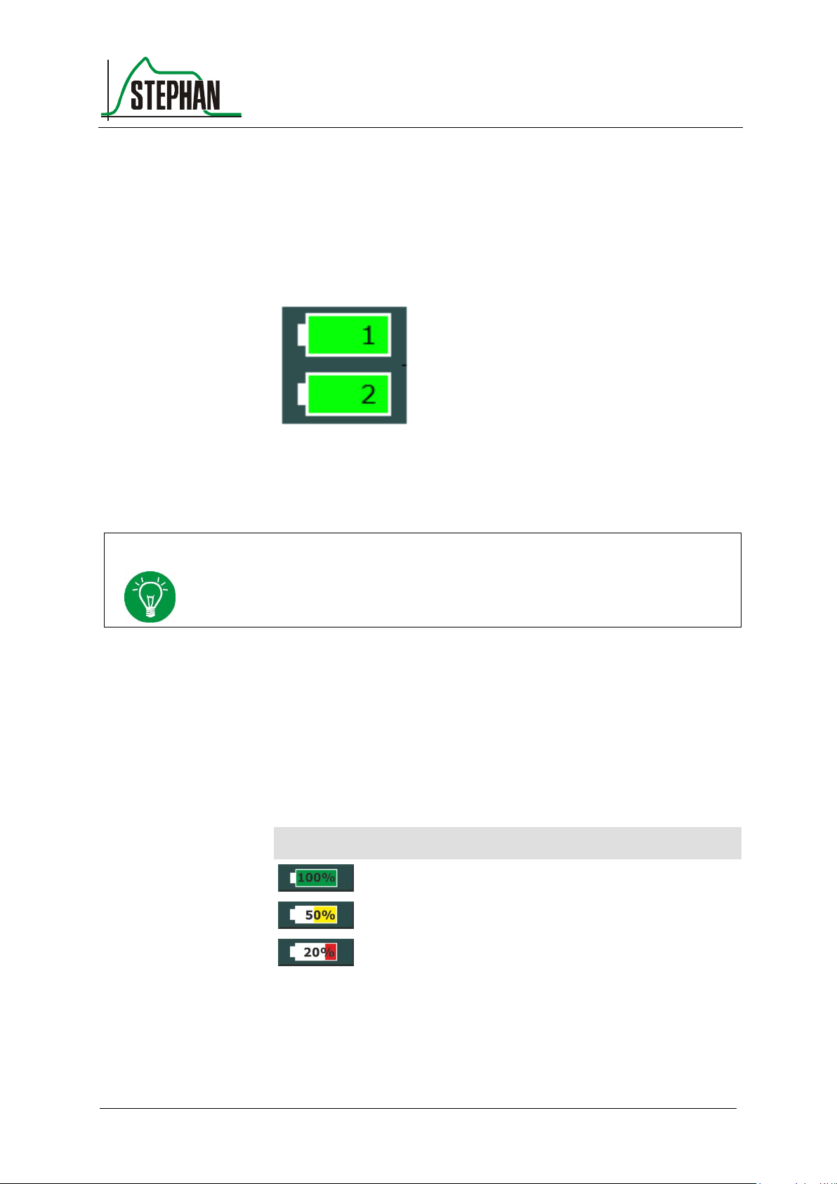
®
3 Design and functional description
Fritz Stephan GmbH
GA-070T-0518V2.7-HAO-EN
71
1 Battery 1 charge indicator
2 Battery 2 charge indicator
NOTE
To ensure the correct function of the battery charge indicator, both the internal and
external battery must be calibrated every six months (see chapter 11.11).
Pictogram
Meaning
Green Capacity between 75 – 100%
Yellow Capacity between 40 – 74%
Red Capacity between 1 – 39%
Battery charge
indicator
3.2.6 Energy supply indicator
This indicator informs the user about the current state of the internal and
external battery. Tap the field to open the "Battery" sub-menu. It contains
detailed information about the status of the energy supply.
Fig. 28: Energy supply indicator
To allow for battery changes during operation, the EVE
can be
TR
equipped with two independent batteries. Their charge levels are
indicated on the display by two icons. The remaining capacity is
indicated by color. In addition, the battery icon shows the remaining
battery level in percent during mains operation and the remaining
operating time in minutes during battery operation.
Tab. 9: Charge level indicator
Page 72
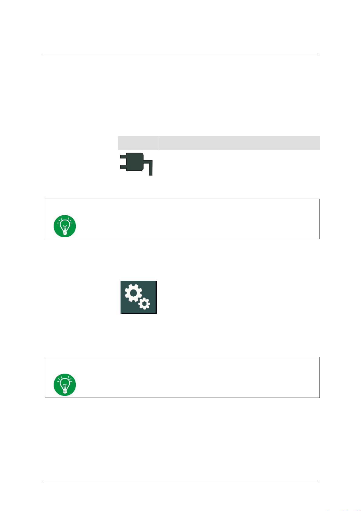
3 Design and functional description
72
GA-070T-0518V2.7-HAO-EN
Fritz Stephan GmbH
Pictogram
Meaning
The plug icon appears in front of both battery indicators
when mains power is connected. The icon disappears from
the display when mains power is disconnected.
NOTE
If mains power is not connected, the battery providing power is shown with a blue
border.
NOTE
This field contains a lock icon if the touchscreen is locked (see chapter 3.1.3).
"Batteries" sub-menu
Mains power
It displays the following parameters for the internal and external battery:
Charge status (%)
Battery life (min)
Charge time (min)
Charge cycles
Tab. 10: Mains power indicator
3.2.7 System settings
Fig. 29: "System Settings" field
Pressing this field opens the "System Settings" sub-menu (see chapter 4).
Page 73
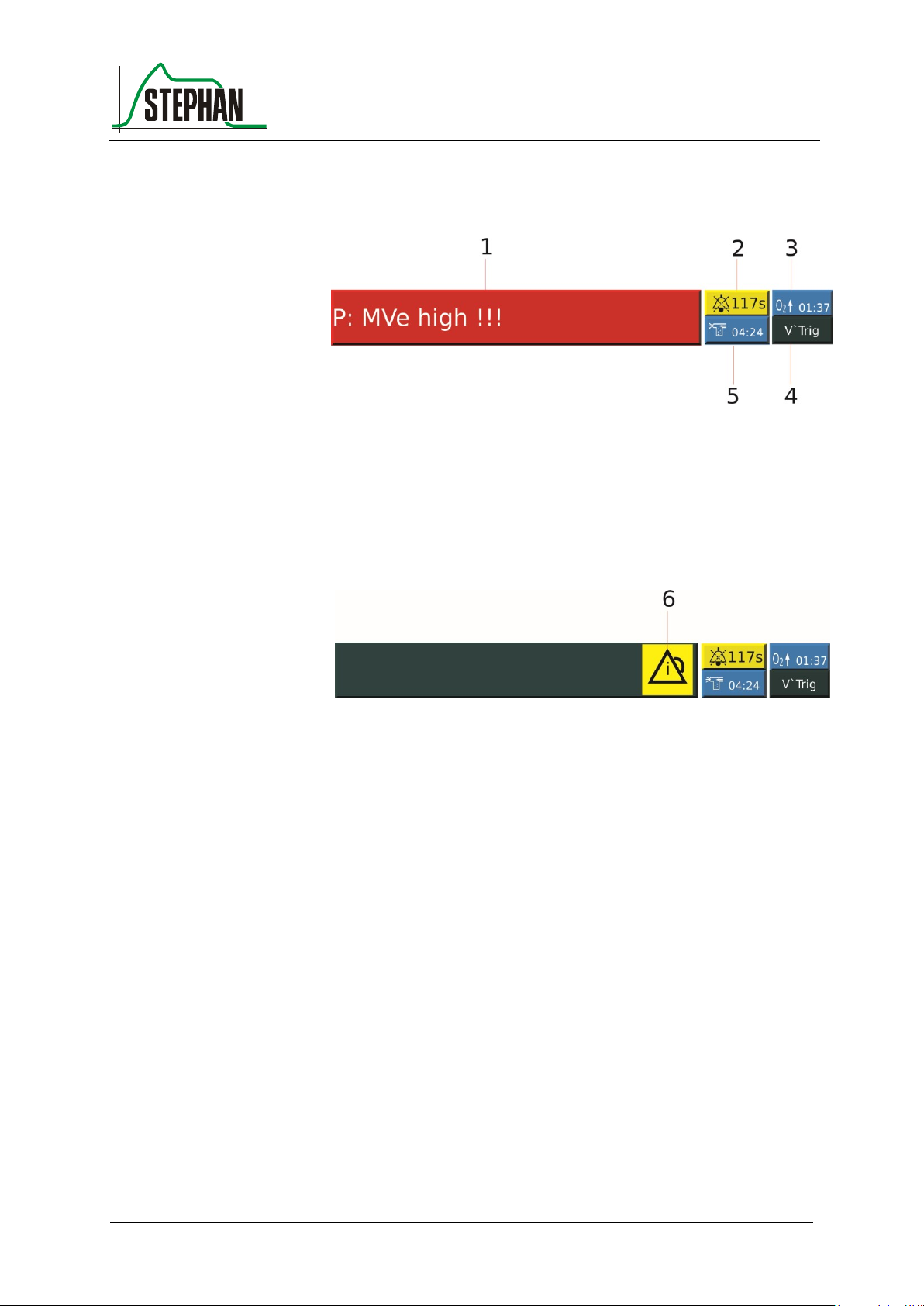
®
3 Design and functional description
Fritz Stephan GmbH
GA-070T-0518V2.7-HAO-EN
73
1 Alarm display
4 Trigger display
2 Alarm suppression time display
5 Nebulization time display
3 Pre-oxygenation time display
6 Alarm history icon
Alarm display and
alarm history
Alarm suppression
display
Preoxygenation display
Nebulization display
3.2.8 Status, alarm and info display
Fig. 30: Status, alarm, and info display with active alarm
Fig. 31: Status, alarm, and info display, alarm history display
The alarm display always shows the active alarm with the highest priority
(notification = blue, MP alarm = yellow, HP alarm = red). Pressing the
alarm display opens the alarm history (see chapter 3.2.3.3). If there are
no active alarms, but a non-acknowledged alarm history exists, the
corresponding icon appears on the alarm display. The icon disappears
after deleting the alarm history.
Pressing the »Alarm suppression« button (see chapter 3.1.2) mutes all
alarms for a duration of two minutes. The corresponding icon appears on
the display, and a countdown timer indicates the remaining alarm
suppression time.
Pressing the »Preoxy« button (see chapter 3.1.3) displays the
corresponding icon, and the preset preoxygenation time starts to count
down.
Pressing the »Aerosol« button (see chapter 3.1.3) displays the
corresponding icon, and the preset nebulization time starts to count down.
Page 74
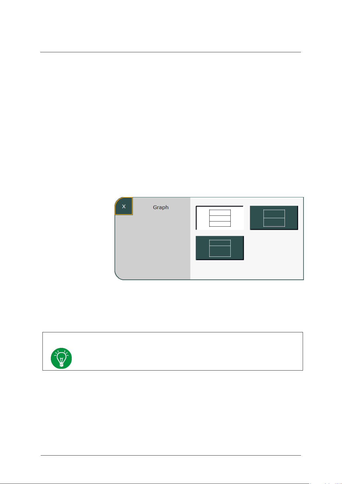
3 Design and functional description
74
GA-070T-0518V2.7-HAO-EN
Fritz Stephan GmbH
NOTE
The system automatically adapts the scaling of the curves and scales to the current
measured values.
Trigger display
Displays the type of trigger used (see chapter 4.2.3).
3.2.9 Graphic display
Pressing the »Graph« button (see chapter 3.2.3.5) opens the graphic
display, which can be customized. The initial layout can be preconfigured in the system settings (see chapter 4.1.2). Three different
layout versions are available.
1. Display of three curves
2. Display of two curves
3. Display of one curve, loop or trend
.
Fig. 32: Graphic display configuration
The top field of the graphic display always shows the pressure curve. The
remaining fields can be freely configured by selecting them.
Page 75
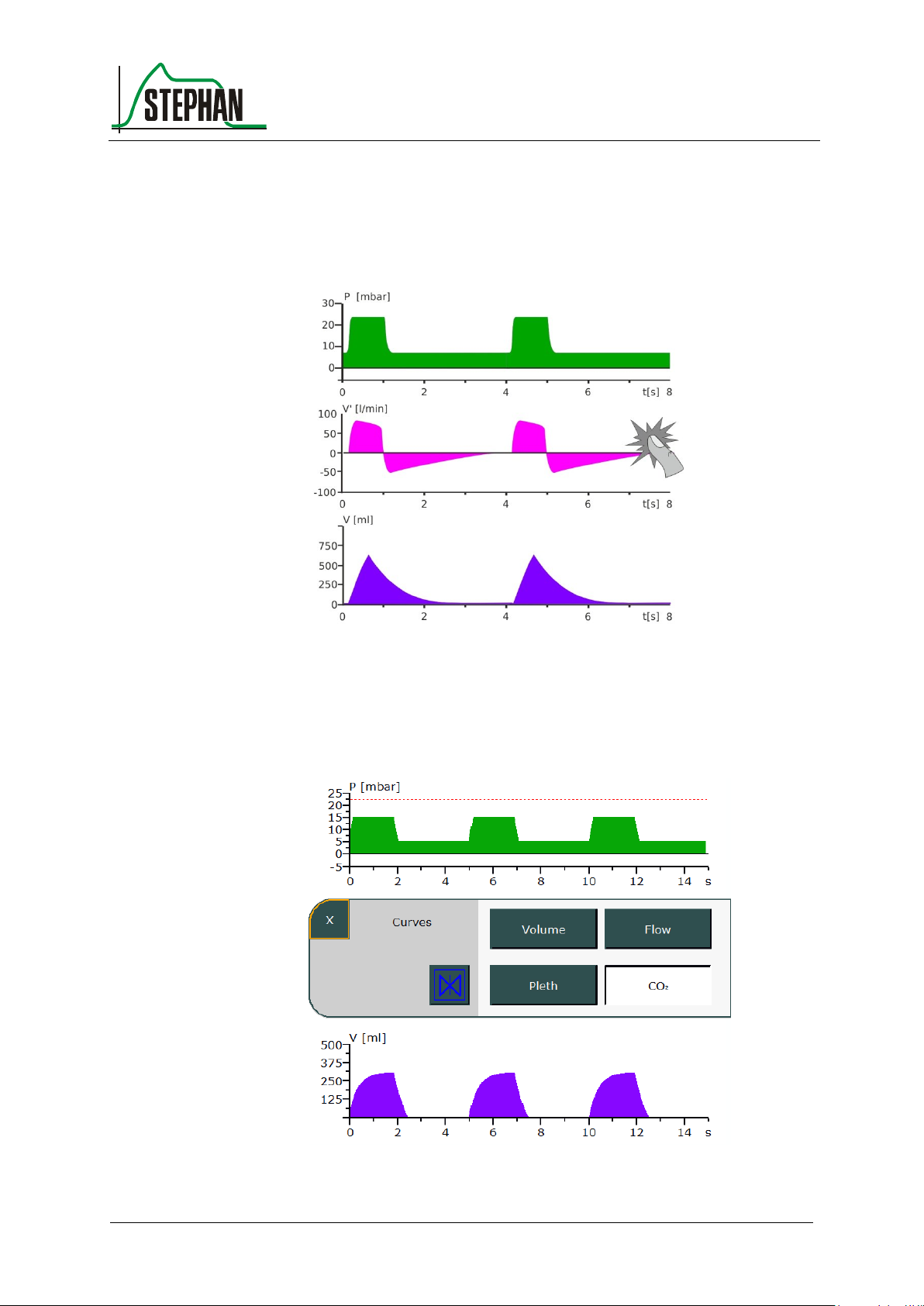
®
3 Design and functional description
Fritz Stephan GmbH
GA-070T-0518V2.7-HAO-EN
75
Configuring the measurement curves 3.2.9.1
Select a measurement curve on the display to change it.
Fig. 33: Graphic display, changing the display
A window with all available measurement curves (volume, flow, CO2 and
plethysmogram) opens. You can now select the desired option.
Fig. 34: Selecting the measurement curve
Page 76
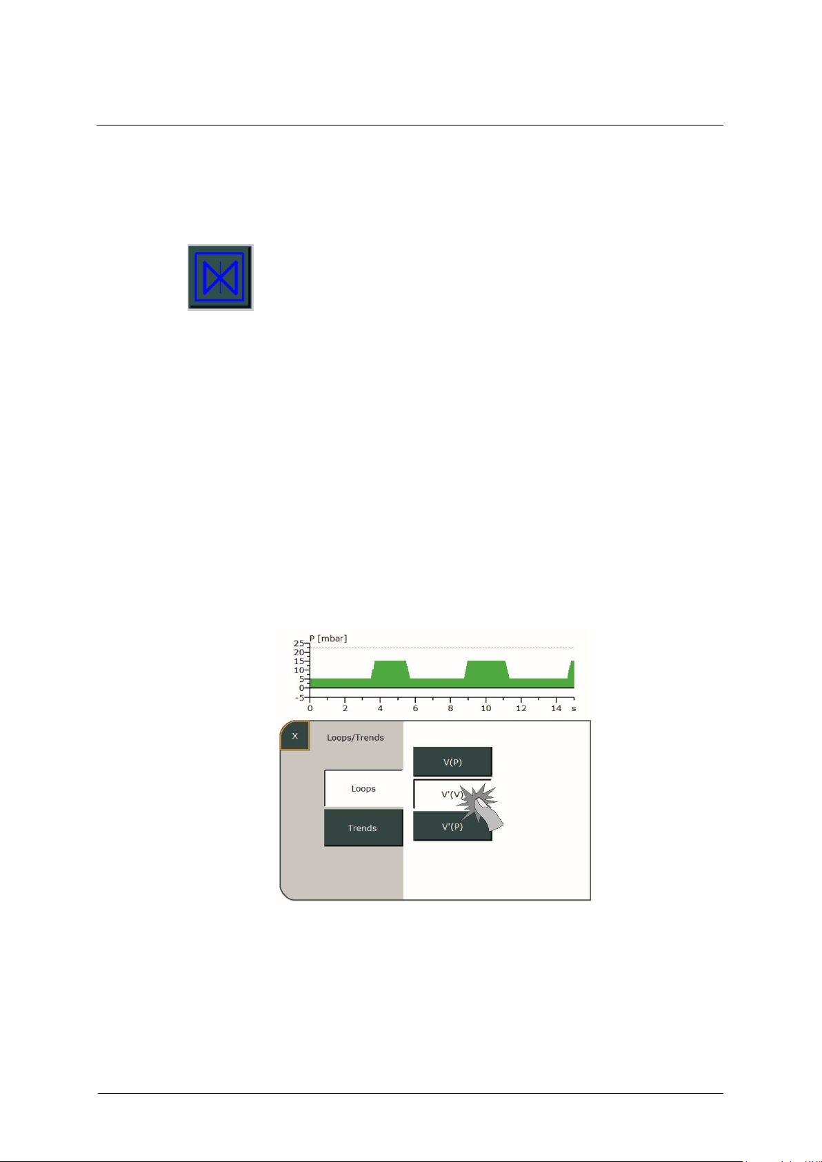
3 Design and functional description
76
GA-070T-0518V2.7-HAO-EN
Fritz Stephan GmbH
Loops
Pressing the »X« field closes the selection window and updates the
graphic display with the new setting.
For a better view, the measurement curves can be frozen on the display.
To do this, press the "Stop" field in the selection window. After
activation, the measurement curves run until the end of the scale and are
then frozen. This mode is ended by pressing the "Stop" field or
automatically after 20 s have passed.
Configuration of loops and trends 3.2.9.2
Layout 3 provides the option of displaying loops and trends.
The lower field of the graphic display must be pressed for this. A submenu opens and the user can choose between loops and trends by
selecting the corresponding field.
If the »Loops« field is selected, available options are displayed on the
right. Pressing the corresponding field lets you display the desired loop in
the graphic display.
Fig. 35: Selecting loops
Pressing the »X« field closes the selection window and shows the loop
including its measured values in the graphic display.
Page 77
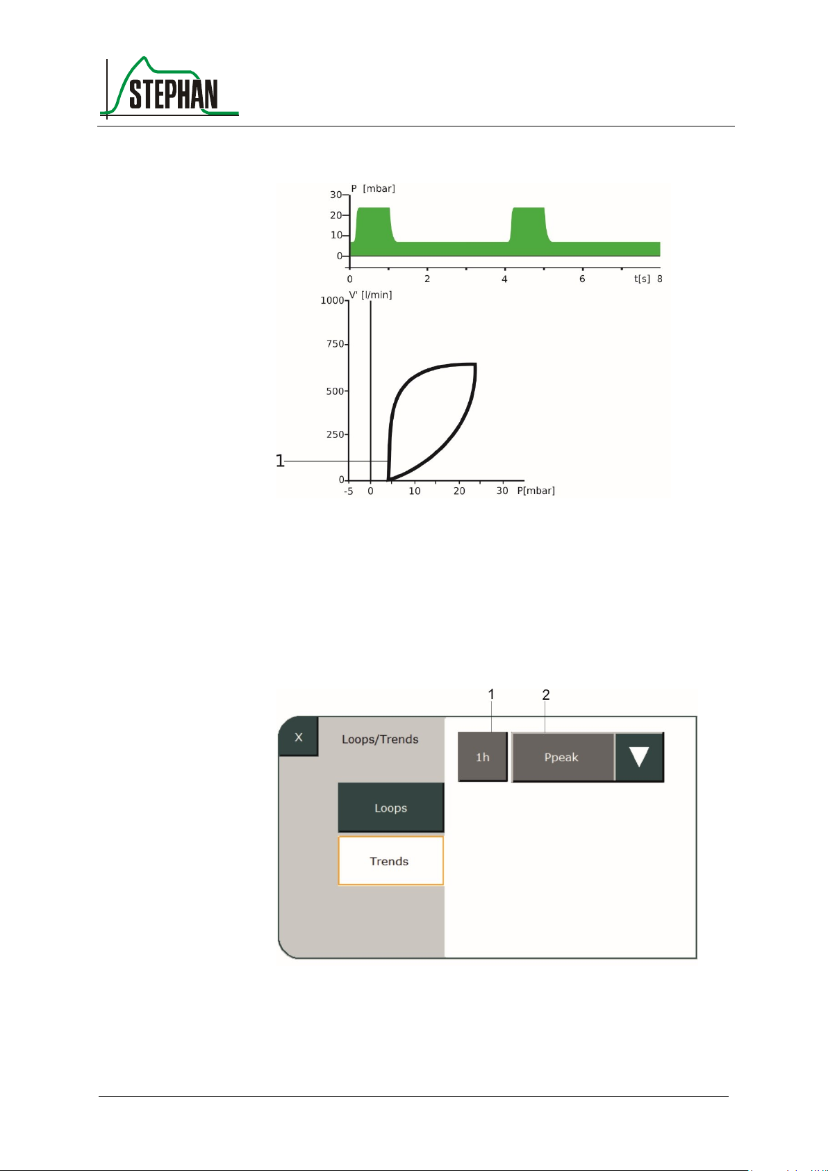
®
3 Design and functional description
Fritz Stephan GmbH
GA-070T-0518V2.7-HAO-EN
77
1 Loop
1 Monitoring time setting
2 Trend selection
Trends
Fig. 36: Loop (here V‘(P))
If the »Trends« field is selected, available options are displayed on the
right.
Fig. 37: Trends selection
Page 78

3 Design and functional description
78
GA-070T-0518V2.7-HAO-EN
Fritz Stephan GmbH
Ppeak
Vte
MVespon
R
SPMet
SPO2
FiO2
Pplat
Vt spon
ftotal
C
Pulse
SPMet
Pplat/
PEEP
Pmean
Vt leak
fspon
RSB
PVI
SPCO
Mve/
Mvespon
PEEP
MVe
O2
PTP
PI
SPOC
ftotal/
fspon
Selectable trends
After selecting the first field, the observation time period can be set via
the "IGR" control knob in the levels 1, 6, 12, 24, 48 and 72 h. Pressing
the arrow key in the second window opens a dropdown menu. Here you
can select the required trend. Up to two trends can be displayed at the
same time for pressure, minute volume and frequency.
Tab. 11: Displayable trends
Page 79
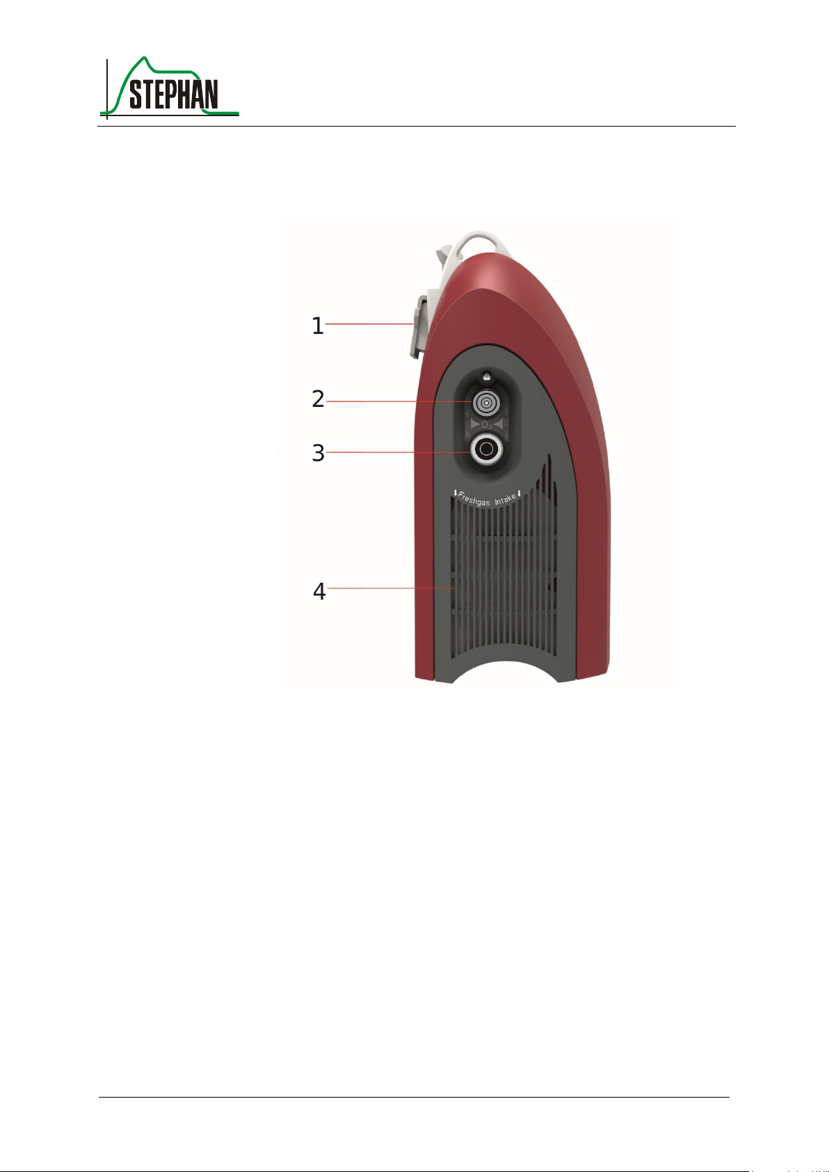
®
3 Design and functional description
Fritz Stephan GmbH
GA-070T-0518V2.7-HAO-EN
79
1 Attachment hook
3 O2 input
2 O2 input
quick coupling
4 Air filter grille
(coarse and HEPA filter)
Attachment hook
3.3 Left side view
Fig. 38: Left side view
The maximum load of the attachment hook is 15 kg.
It can be used to attach the EVE
TR
to
a standard rail (10 x 25 mm)
hospital beds (Ø 38 mm)
Stretchers
Page 80
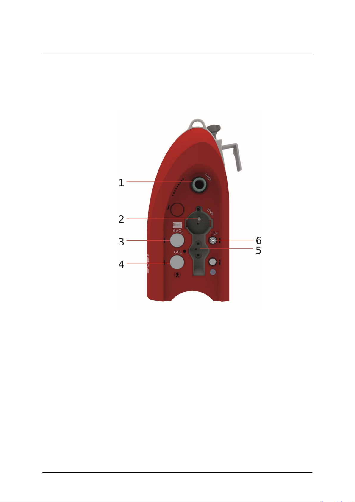
3 Design and functional description
80
GA-070T-0518V2.7-HAO-EN
Fritz Stephan GmbH
1 Insp. = gas outlet opening
Inspiration tube connection
3 SpO2 sensor connection
4 CO2 sensor connection
2 Exp. = gas return opening
Expiration tube connection
5 Flow sensor connection
6 Aerosol nebulizer connection
3.4 Right side view
Fig. 39: Right side view
Page 81
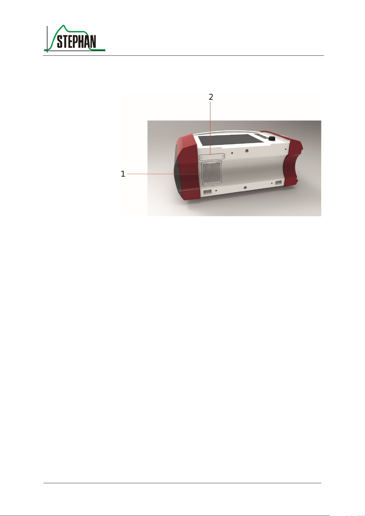
®
3 Design and functional description
Fritz Stephan GmbH
GA-070T-0518V2.7-HAO-EN
81
1 Fan
2 Cover for the SD card slot
3.5 Bottom view
Fig. 40: Bottom view
Page 82
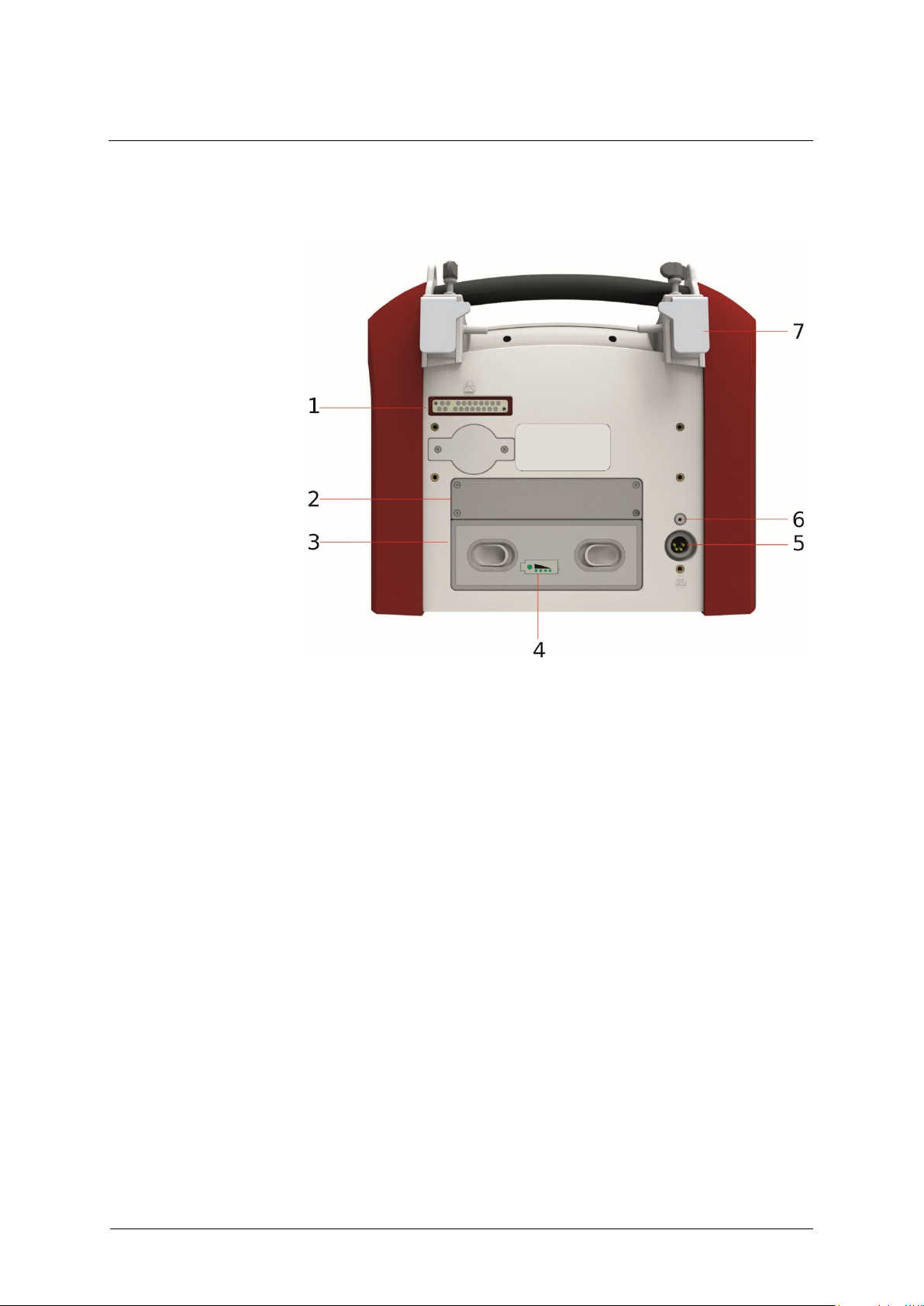
3 Design and functional description
82
GA-070T-0518V2.7-HAO-EN
Fritz Stephan GmbH
3.6 Rear view
1 Docking station interface
5 Power supply input
2 Internal battery 1
6 Reset button
3 External battery 2 (optional)
7 Adjustable bracket
4 External battery charge level
indicator
External battery
charge level indicator
Reset button
Fig. 41: Rear view
The charge level indicator lets you check the external battery (optional)
even when the device is switched off. Pressing the field shows the current
charge level using LEDs.
Pressing the Reset button causes the EVE
not reset the ventilator to factory settings.
to restart. However, it does
TR
Page 83
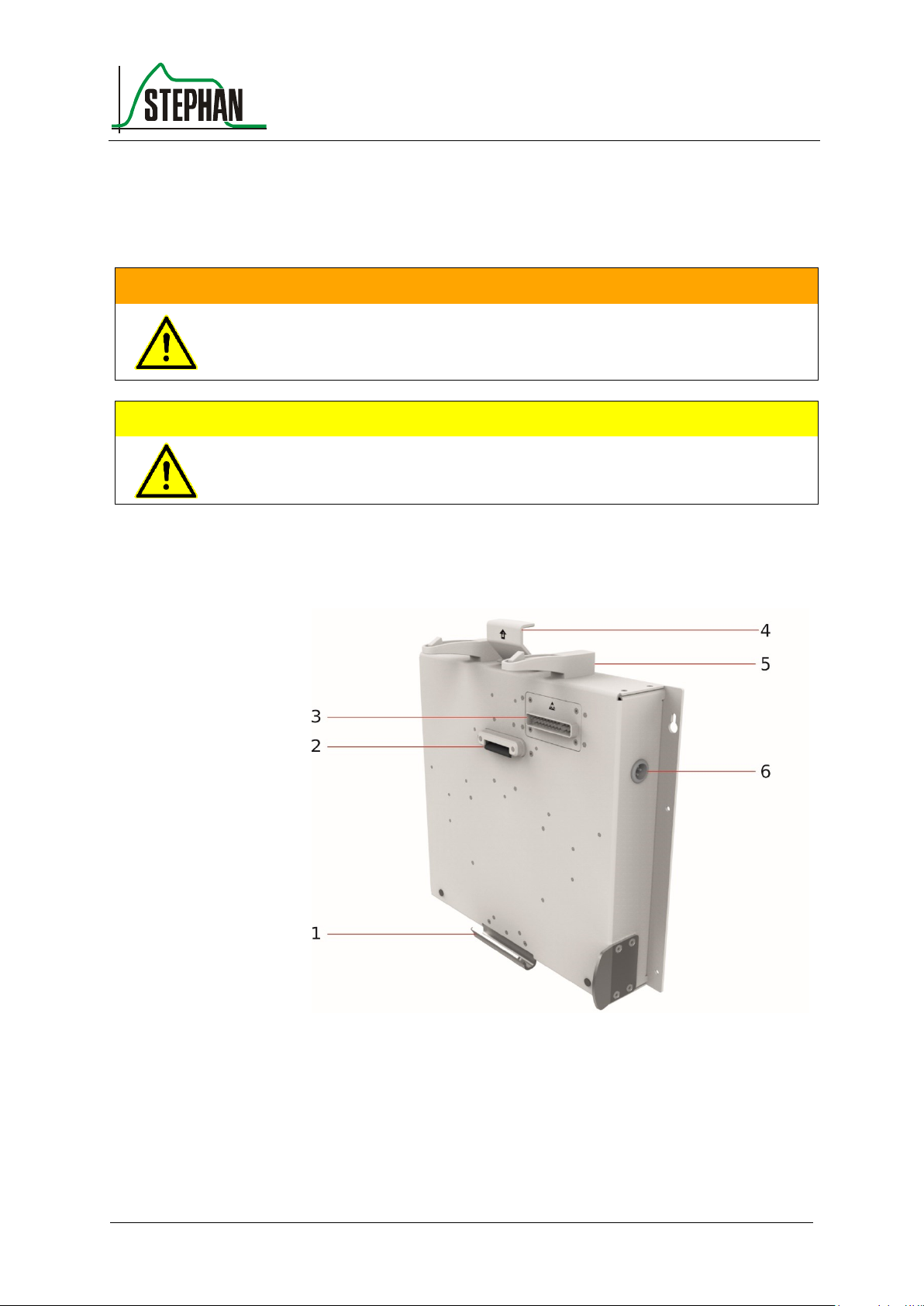
®
3 Design and functional description
Fritz Stephan GmbH
GA-070T-0518V2.7-HAO-EN
83
WARNING
When inserting the EVETR into the bracket, never place your hands or fingers
between the device and the bracket. Otherwise, injuries due to crushing may result.
Make sure the device locks into place!
CAUTION
The safety catch of the brackets must be checked at least every four weeks for
intactness and correct functioning.
1 EVETR attachment hook
4 Lock/unlock latch
2 EVETR bracket
5 EVETR safety catch
3 EVETR interface
6 12/24 V on-board power
supply input
3.7 Brackets
3.7.1 Ambulance bracket
Fig. 42: Ambulance bracket
Page 84
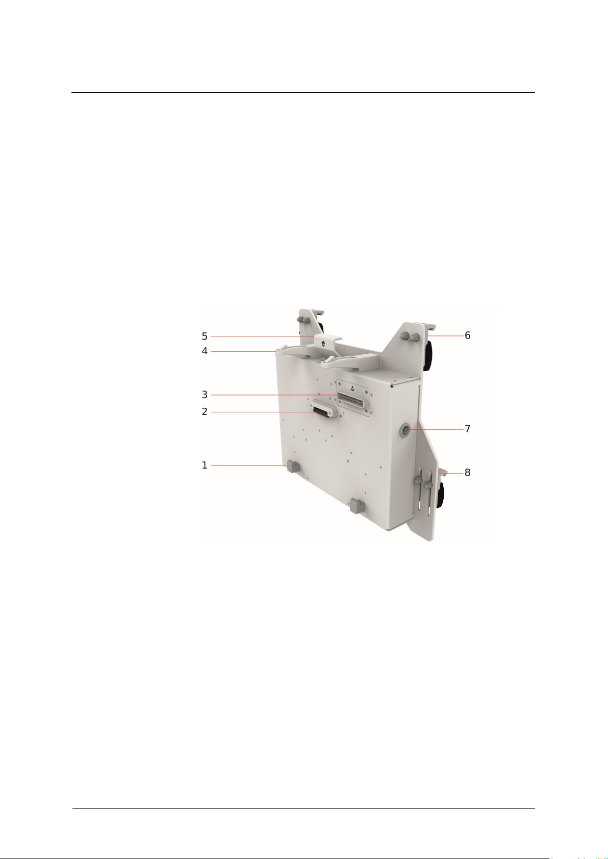
3 Design and functional description
84
GA-070T-0518V2.7-HAO-EN
Fritz Stephan GmbH
1 EVETR attachment hook
5 Lock/unlock latch
2 EVETR bracket
6 Standard rail bracket
3 EVETR interface
7 12/24 V on-board power
supply input
4 EVETR safety catch
8 Height-adjustable rail system
bracket
Place the EVETR, including carry system (see chapter 3.7.3), into the
attachment hooks (item 1) and push toward the ambulance bracket until
first the safety catch (item 5) and then the bracket (item 2) lock into place
with a click.
To remove the ventilator, press the lock/unlock latch (item 4). The device
releases and can be removed from the bracket.
3.7.2 Helicopter bracket
Fig. 43: Helicopter bracket
Place the EVETR into the attachment hooks (item 1) and push toward the
helicopter bracket until first the safety catch (item 6) and then the bracket
(item 2) lock into place with a click.
To remove the ventilator, press the lock/unlock latch (item 5). The device
releases and can be removed from the bracket.
Page 85
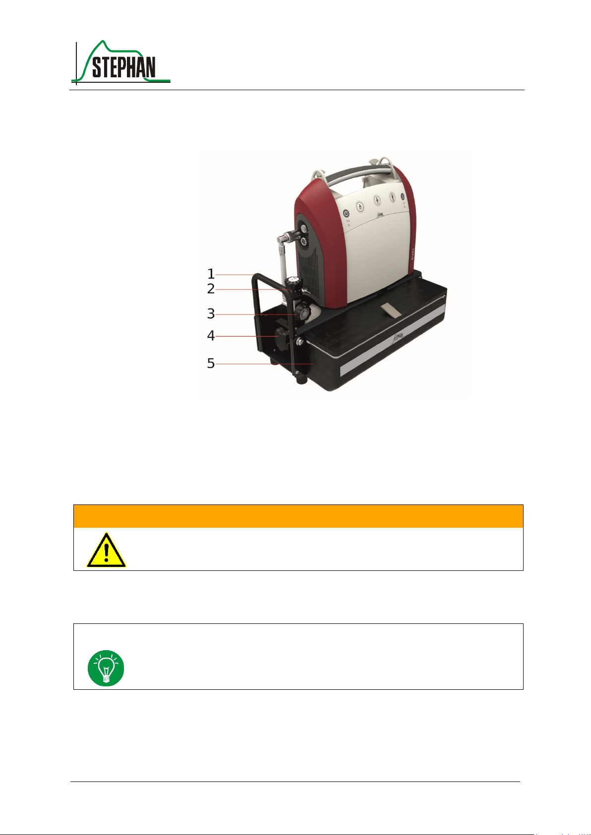
®
3 Design and functional description
Fritz Stephan GmbH
GA-070T-0518V2.7-HAO-EN
85
1 Safety guard
4 Oxygen cylinder
2 Pressure regulator
5 Bag for tube system and
accessories
3 Manometer
WARNING
Only use the original carry system from FRITZ STEPHAN GMBH, otherwise device
damage may result.
NOTE
Observe the manufacturer’s service and operating manuals!
3.7.3 Carry system
Fig. 44: EVETR carry system
Built-in pressure regulator 3.7.3.1
Page 86

Page 87

®
4 System Settings
Fritz Stephan GmbH
GA-070T-0518V2.7-HAO-EN
87
NOTE
Changes are automatically saved when exiting a sub-menu and remain in effect when
restarting the device, with the exception of the Masimo Rainbow SET® parameters.
4 System Settings
Pressing the System field opens the "System Settings" menu.
Fig. 45: System field
All the fields in the various menus can be touch-activated. Turn the
control knob to change the parameters. Complete your input by pressing
the control knob or touching the field again.
The "System Settings" menu is divided into the following sub-menus:
System
Sensors
Display
Setup
They are described below.
Page 88
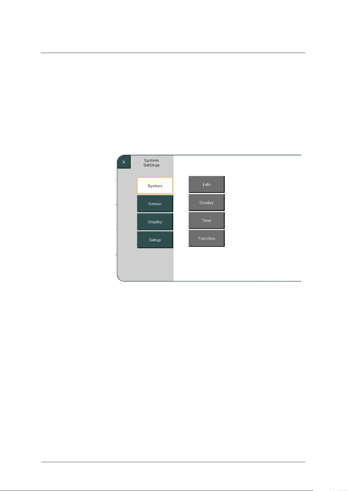
4 System Settings
88
GA-070T-0518V2.7-HAO-EN
Fritz Stephan GmbH
4.1 System
This lets you access the following sub-menus:
Info
Display
Time
Function
Fig. 46: System
Page 89

®
4 System Settings
Fritz Stephan GmbH
GA-070T-0518V2.7-HAO-EN
89
4.1.1 Info
Device serial number
(ID-Number)
Mainboard SW
Operating hours
Bootloader SW
Date
MAC address
Service date
Masimo module (optional)
Blower module
Bootloader Blower
Blower SW
Bootloader motor
Blower SW motor
PSU SW (power supply)
Akkupack2 SW (battery pack 2)
Battery SW
Bootloader PSU
Akkupack1 SW (battery pack 1)
Bootloader battery
NOTE
Settings made in the "Display" sub-menu are also used when switching manually
between day/night mode in the function area (see chapter 3.1.3).
Mainboard SW
Blower SW
PSU SW
(power supply)
This sub-menu lets you access the following device-specific data:
4.1.2 Display
4.1.3 Time and Date
This sub-menu lets you set the date and time.
This sub-menu lets you separately adjust the display brightness for
day and night operation in the range of 20 – 100%. You can also
determine a start time for both operating modes. Use the »Settings
activated« box to activate/deactivate the configured settings.
Page 90
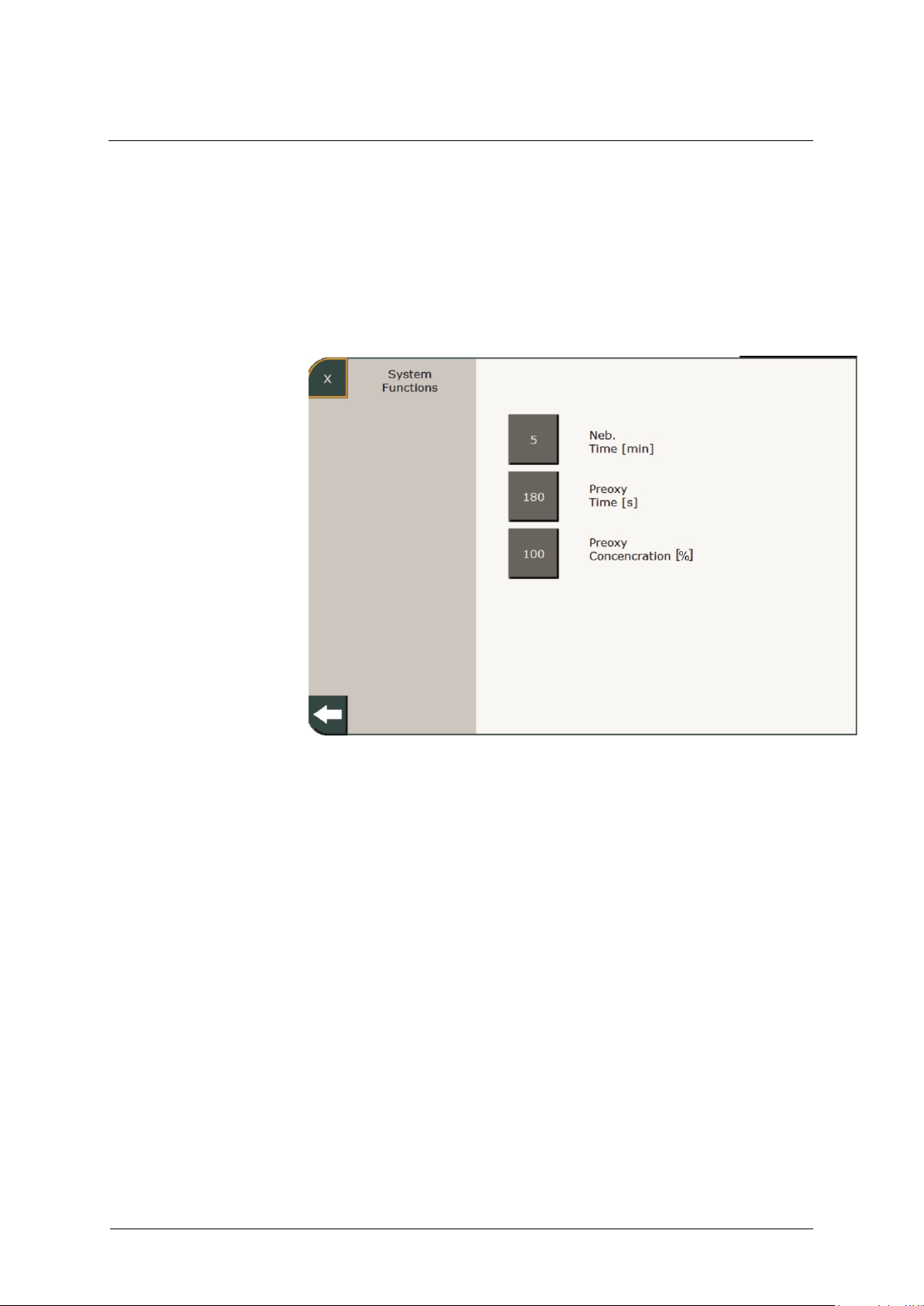
4 System Settings
90
GA-070T-0518V2.7-HAO-EN
Fritz Stephan GmbH
4.1.4 Function
Aerosol time
Preoxy time
Preoxy %
This sub-menu lets you configure the parameters for the »Aerosol« and
»Preoxy«, buttons in the function area (see chapter 3.1.3).
Fig. 47: Function
Lets you set the aerosol nebulization time (5 – 30 min). Aerosol
nebulization is triggered by pressing the »Aerosol« button.
Lets you set duration of the preoxygenation (10 – 180 s) that is triggered
when the »Preoxy« button is pressed.
Setting for the inspiratory oxygen concentration administered when the
»Preoxy« button is pressed. You can select an inspiratory oxygen
concentration between 21 and 100%.
Page 91
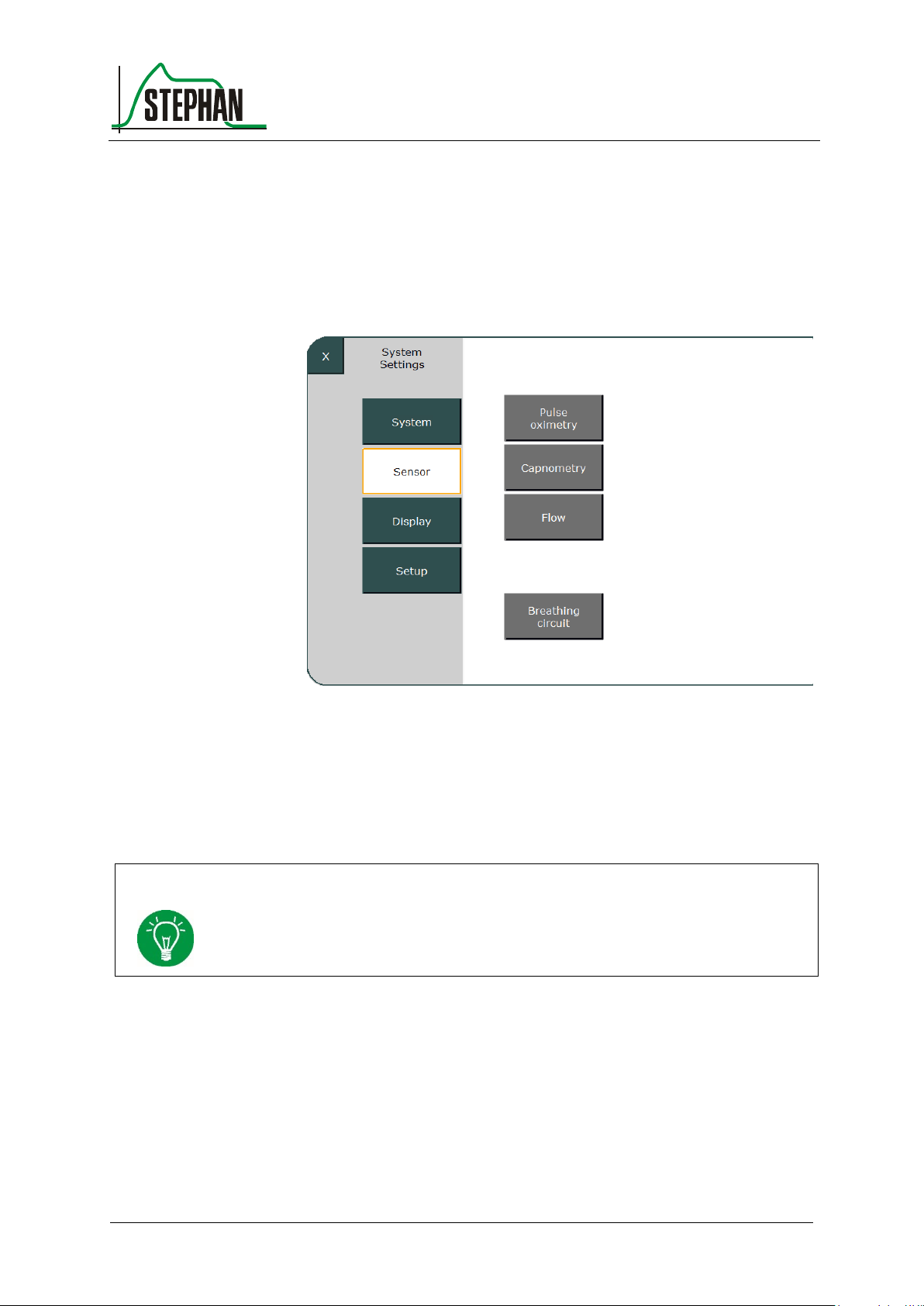
®
4 System Settings
Fritz Stephan GmbH
GA-070T-0518V2.7-HAO-EN
91
4.2 Sensors
NOTE
The configured settings are used for the current ventilation process when exiting the
menu. The user-defined configuration for the Masimo sensors is not permanently
saved. Restarting the ventilator will reset it to the factory settings.
Selecting the corresponding fields in the sub-menu lets you activate or
configure the sensors for pulse oximetry, capnometry, and flow. The tube
system used is configured here.
Fig. 48: Sensor sub-menu
4.2.1 Pulse oximetry
This sub-menu lets you configure the sensors for pulse oximetry.
Page 92
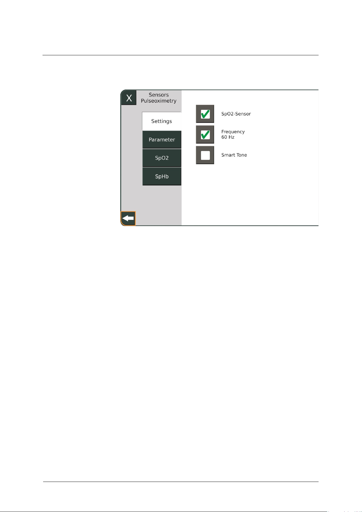
4 System Settings
92
GA-070T-0518V2.7-HAO-EN
Fritz Stephan GmbH
SpO2-Sensor
Frequency setting
Smart Tone
Settings 4.2.1.1
Fig. 49: Settings sub-menu
Turns the SpO2 sensor on/off
This lets you switch the frequency of the sensor from 50 Hz (default
value) to 60 Hz.
Selecting this function enables the acoustic pulse signal. Otherwise, the
Smart Tone is disabled.
Page 93
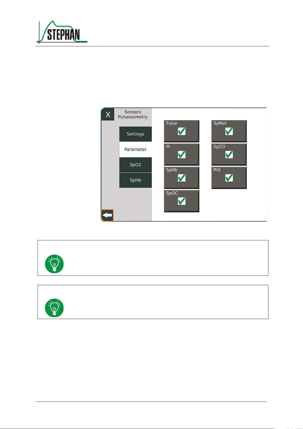
®
4 System Settings
Fritz Stephan GmbH
GA-070T-0518V2.7-HAO-EN
93
NOTE
The number of measurement parameters is optional and can be configured upon
customer request. Parameters not contained in the package are grayed out and not
selectable.
NOTE
The SpOC parameter can only be selected if SpHb is activated.
Parameter 4.2.1.2
When the SpO2 sensor is activated (see chapter 4.2.1.1), this menu lets
you turn on/off the measurement of the Pulse, PI, SpHb, SpMet, SpCO,
SpOC, and PVI parameters.
Fig. 50: Activating the measured values
Page 94
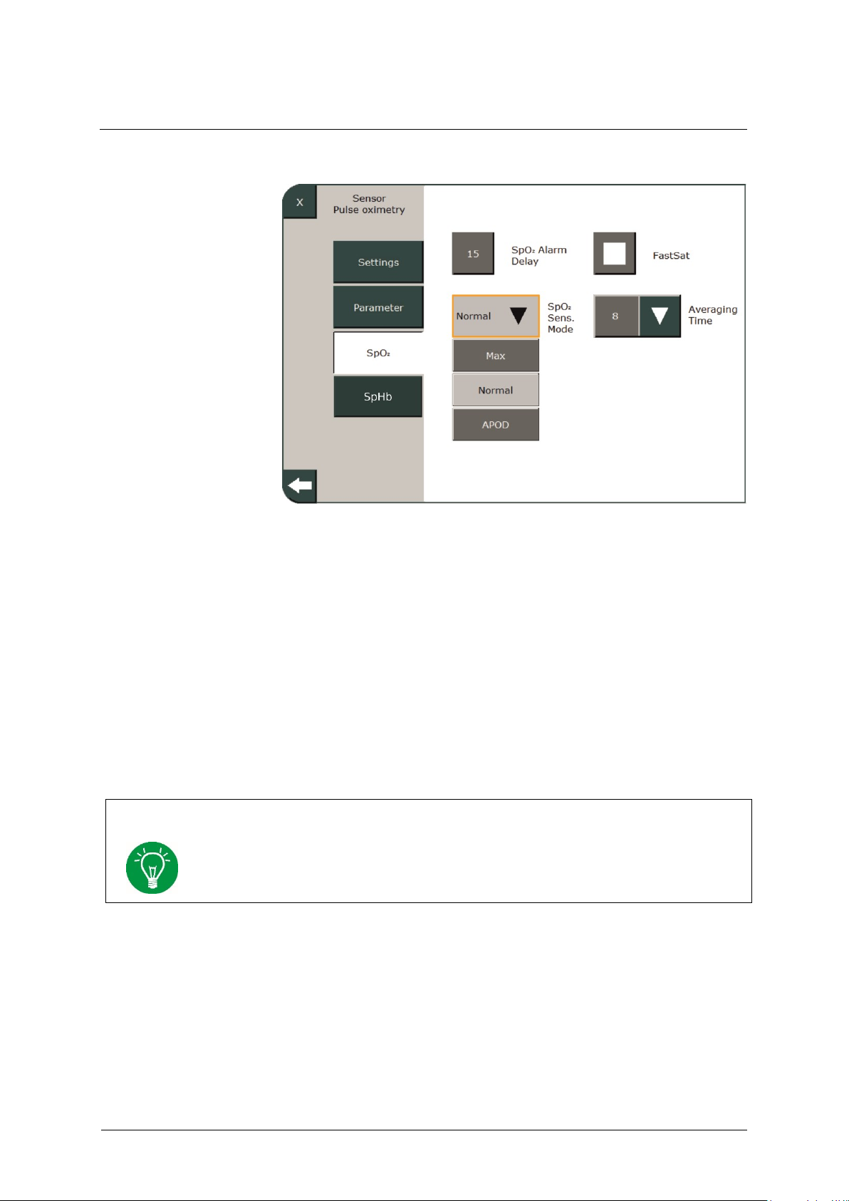
4 System Settings
94
GA-070T-0518V2.7-HAO-EN
Fritz Stephan GmbH
SpO
NOTE
When FastSat® mode is activated, the averaging time depends on the input signal. If a
range is specified for the averaging time of 2-4 s or 4-6 s, the averaging time will be
within the selected range.
SpO2 Alarm Delay
SpO2 Sensor Sensitivity
FastSat®
Averaging Time
4.2.1.3
2
Fig. 51: SPO
2
This lets you set a delay for the SpO2 alarm. Possible settings are 0 s, 5 s,
10 s, and 15 s. The default is 15 s.
This sub-menu lets you configure the sensitivity of the SpO2 sensor at the
following levels: Normal, Max, and APOD™ (Adaptive Probe-Off
Detection Technology). APOD™ offers the best detection of the three
sensitivity levels if the sensor becomes detached from the patient.
This lets you activate/deactivate FastSat® mode. This function monitors
rapid changes of the arterial O2 level.
The signal averaging time can be set to 2 – 4, 4 – 6, 8, 10, 12, 14, or 16 s.
The oximeter continuously measures the values over the preset time and
then displays the mean value.
Page 95
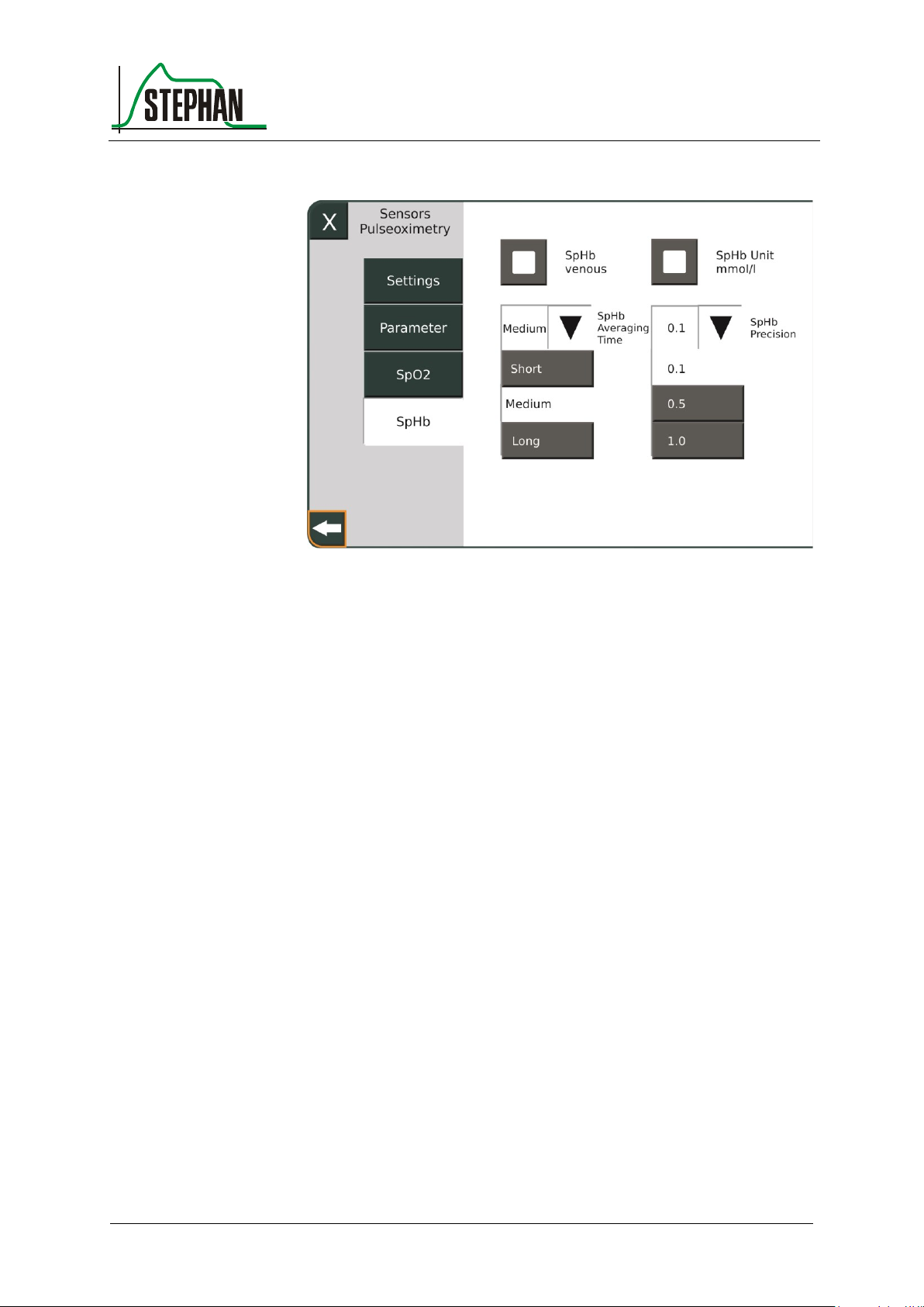
®
4 System Settings
Fritz Stephan GmbH
GA-070T-0518V2.7-HAO-EN
95
SpHb venous
SpHb Units
SpHb Averaging Time
SpHb Precision
SpHb 4.2.1.4
Fig. 52: SpHb
Select this option for venous instead of arterial measurement of the SpHb
value. It is disabled by default.
This sub-menu lets you select the units for the SpHb value. The following
settings are available:
g/dl (default)
mmol/l
The signal averaging time can be set to the following levels: Short,
Medium (default), and Long. The oximeter continuously measures the
values over the preset period and then displays the mean value.
This lets you set the signal precision to the following levels: 0.1 (default),
0.5, and 1.0.
Page 96
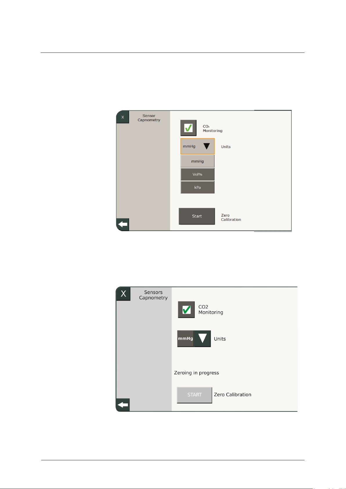
4 System Settings
96
GA-070T-0518V2.7-HAO-EN
Fritz Stephan GmbH
4.2.2 Capnometry
This lets you activate/deactivate CO2 monitoring (optional).
Fig. 53: Capnometry
In addition, you can select the unit (mmHg, kPa, and Vol.%) and choose
to run zero calibration on the sensor (see chapters 8.1.5 and 8.2.5).
Fig. 54: Running zero calibration
Page 97
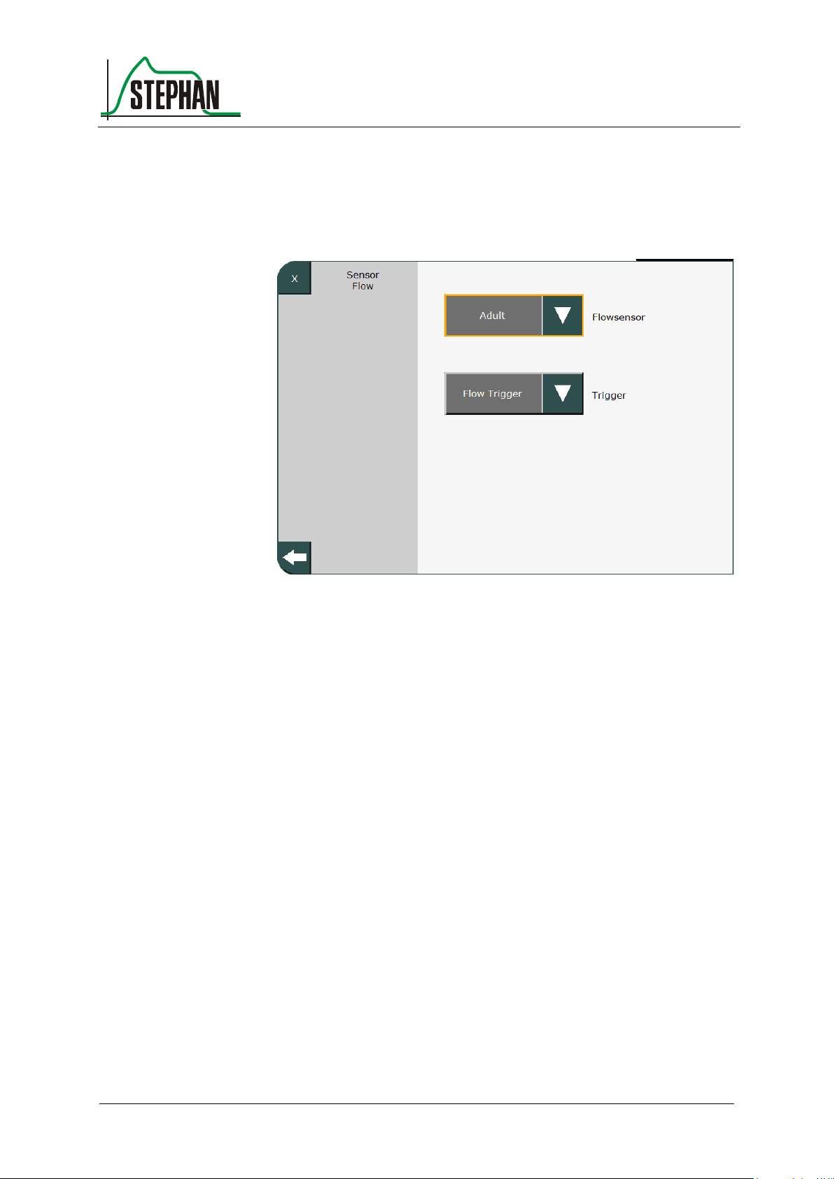
®
4 System Settings
Fritz Stephan GmbH
GA-070T-0518V2.7-HAO-EN
97
4.2.3 Flow
This sub-menu lets you configure the flow sensor.
Fig. 55: Configuring the flow sensor
Select from the following settings for the flow sensor:
Adult
Infant (child)
PNT B
OFF
Furthermore, the flow trigger can be switched on or off here.
Page 98
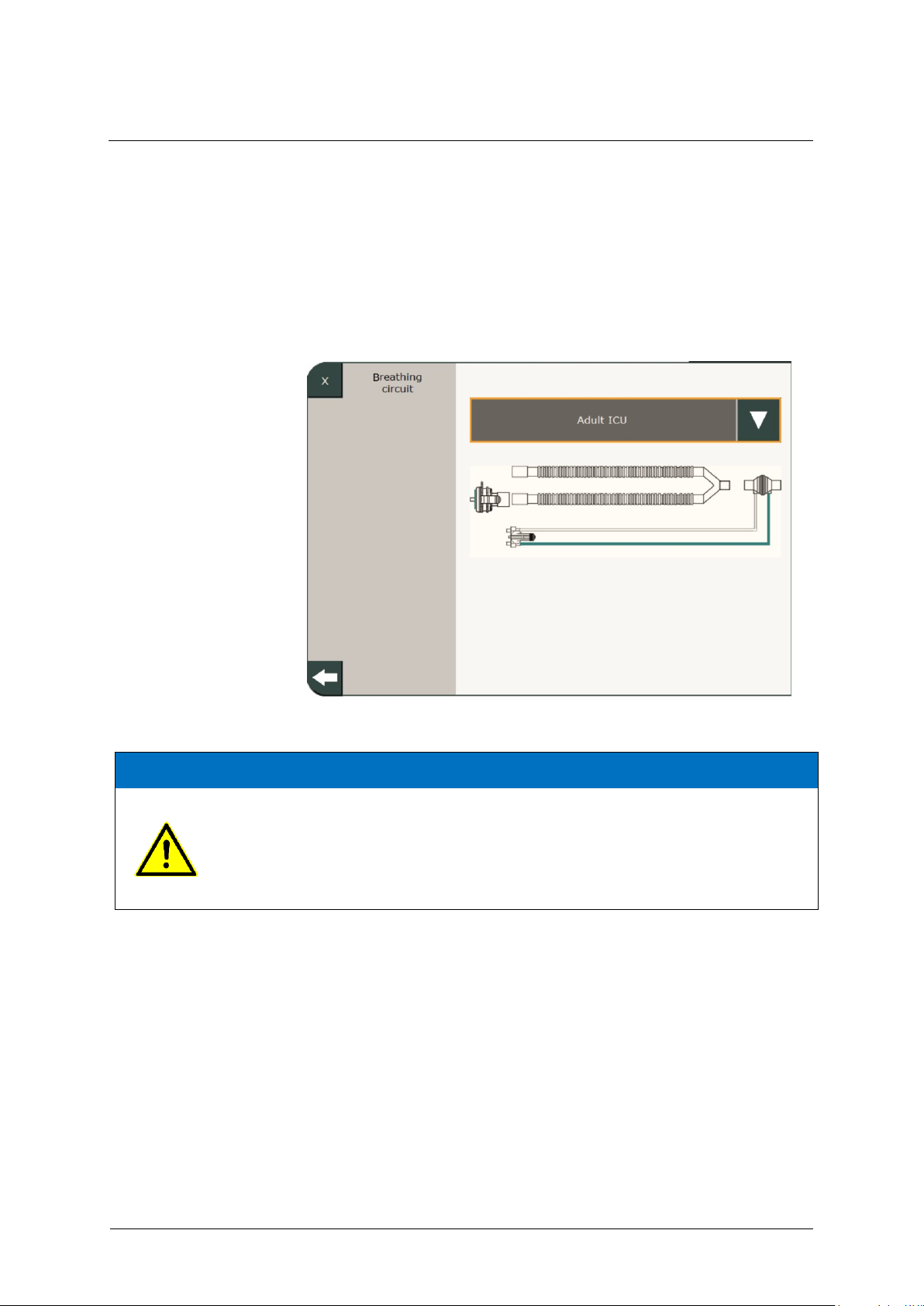
4 System Settings
98
GA-070T-0518V2.7-HAO-EN
Fritz Stephan GmbH
ATTENTION
Fritz Stephan GmbH explicitly recommends that only patient tube systems included in
the list of accessories are used. Otherwise, ventilator function may be impaired!
If it is necessary to use a non-standardized tube system that has not been tested by
FRITZ STEPHAN GMBH, select the "Other Tube System" option. Then enter the tube
system's parameters manually.
4.2.4 Ventilation tube system
Standard tube systems are preconfigured for the various patient groups. If
other tube systems are used, make the appropriate settings in this menu or
in the Ventilation Breathing System menu (see chapter 6.7). The
corresponding tube system must be selected for this based on the type
designation or a pictogram.
Fig. 56: Presetting for the patient tube system
Page 99
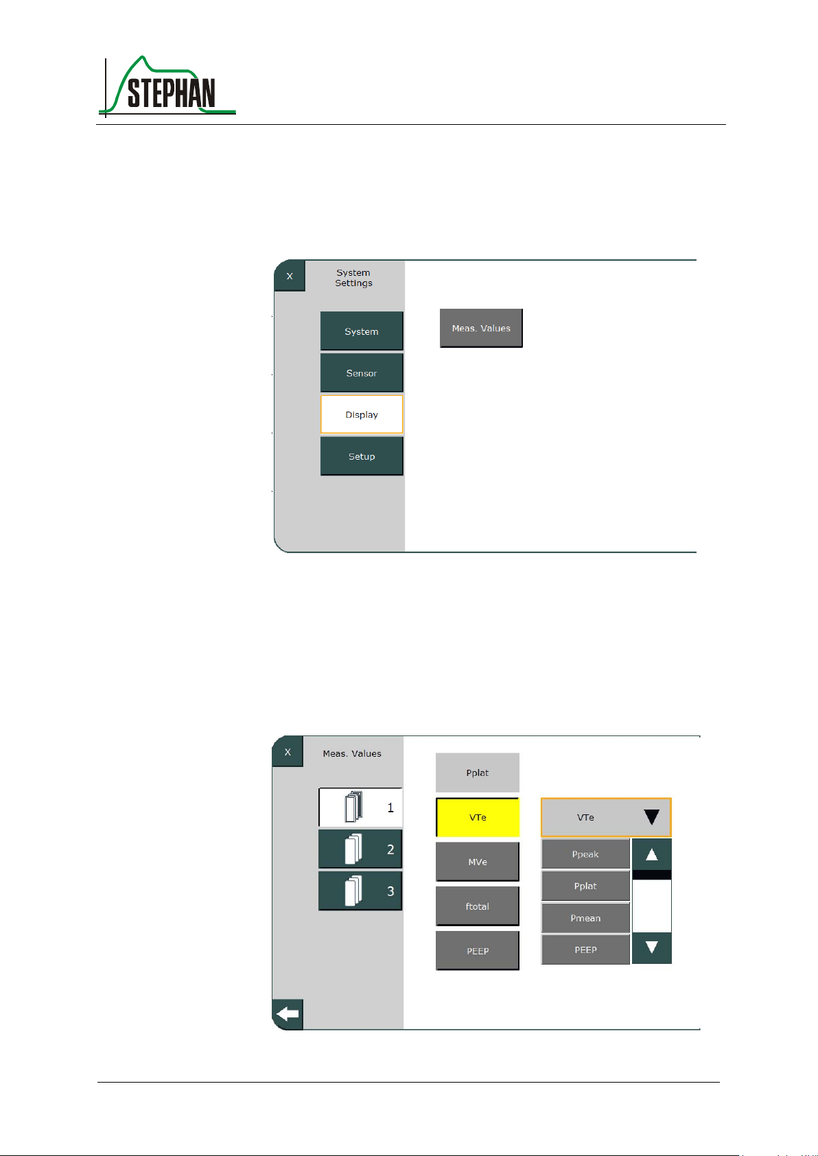
®
4 System Settings
Fritz Stephan GmbH
GA-070T-0518V2.7-HAO-EN
99
4.3 Display
This sub-menu lets you configure the measured value display.
Fig. 57: Display sub-menu
4.3.1 Measured values
The three sets of the measured value display (see chapter 3.2.2) can be
freely configured by the user in this sub-menu.
Fig. 58: Configuring the measured values
Page 100
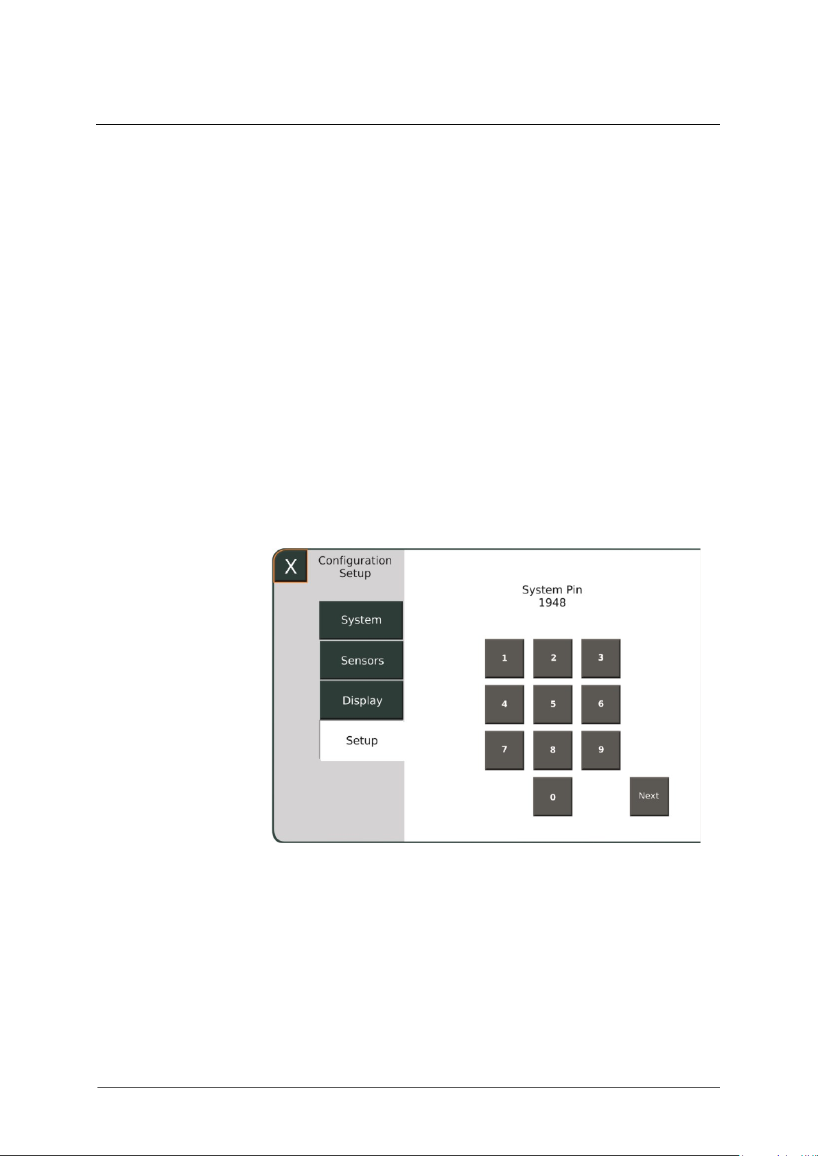
4 System Settings
100
GA-070T-0518V2.7-HAO-EN
Fritz Stephan GmbH
4.4 Setup
Start by selecting the desired set. The current measurement fields appear
on the right side. Next, select the value to be changed. This is illuminated
yellow.
Next, use the touchscreen or control knob to open a drop-down menu
with all available measurement fields on the left side. Use the arrow
buttons to select and the touchscreen or control knob to activate the
desired field, which is immediately added to the measured value bar.
Repeat as necessary until configuration is complete. Changes are
automatically saved when exiting the menu and remain in effect after
restarting the EVETR.
The Setup menu lets you make changes and configure settings that
directly affect the ventilator's therapy settings. For this reason, this area is
protected by a 4-digit code 1948 to be entered on the touchscreen.
Fig. 59: Entering the code
 Loading...