

Page 1
Operation Manual
Benutzerhandbuch
Mode d’Emploi
Page 2

Operation Manual
Page 3

Operation Manual by Ashley Shepherd
Revision and Quality Control: Cristina Bachmann, Heiko Bischoff, Marion Bröer, Sabine Pfeifer, Heike Schilling
The information in this document is subject to change without notice and does not represent a commitment on the part
of Steinberg Media Technologies GmbH. No part of this publication may be copied, reproduced or otherwise transmitted or recorded, for any purpose, without prior written permission by Steinberg Media Technologies GmbH.
All product and company names are ™ or ® trademarks of their respective owners. Windows XP is a trademark of
Microsoft Corporation. Windows Vista is a registered trademark or trademark of Microsoft Corporation in the United
States and/or other countries. The Mac logo is a trademark used under license. Macintosh and Power Macintosh are
registered trademarks.
Release Date: August 31, 2009
© Steinberg Media Technologies GmbH, 2009.
All rights reserved.
Page 4

Table of Contents
Page 5

6 Introduction
7 About this manual
7 What can the SyncStation do?
7 Clock distributor
7 Machine control
7 Timecode synchronizer
7 SyncStation extended System Link
8 GPIO (General Purpose In/Out)
8 Synchronizing with the SyncStation
8 Synchronization basics
8 Timecode (positional references)
10 Clock sources (speed references)
11 Frame reference (phase)
11 Machine control
13 Connecting the SyncStation
14 The inputs and outputs on the SyncStation rear panel
14 USB connection
15 Frame and clock reference inputs
15 Slave clocks (outputs)
15 Machine control
15 GPIO (General Purpose Input Output)
16 SyncStation Controls
17 Front panel controls
17 Cursor buttons and indicator
17 Status LEDs
17 Reset button
18 The SyncStation display
18 Operation display mode
19 Settings Menu display mode
20 Resetting the SyncStation from Nuendo
20 The SyncStation 9-Pin window in Nuendo
20 The SyncStation Status window in Nuendo
21 Menu Reference
23 Root menu
23 Unit menu
23 Unit 01 - Master & Timecode Source
24 Unit 02 - Frame Reference
25 Unit 03 - Timecode Standard
25 Unit 04 - Reference Frame Rate
25 Unit 05 - System Link
25 Unit 06 - System Link Input
26 Unit 07 - Install Template
26 Unit 08 - Line 2 Display
26 Clock menu
26 Clock 01 - Clock Reference
27 Clock 02 - System Clock Rate
27 Clock 03 - Audio Pull/Varispeed 0.1%
28 Clock 04 - Audio Pull/Varispeed 4%
28 Clock 05 - Wordclock A
29 Clock 06 - Wordclock B
29 Clock 07 - Wordclock C
29 Clock 08 - Wordclock D
29 Clock 09 - AES 1/AES 2 Output
30 Clock 10 - Opto/SPDIF Output
30 Clock 11 - Wordclock Input Rate
31 P2 Out menu
31 P2out 01 - Record Tracks
31 P2out 02 - Position Request
32 P2out 03 - Position From
32 P2 In menu
32 P2in 01 - Device ID
33 P2in 02 - RS422-In Track Arming
33 MIDI menu
33 MIDI 01 - MTC -> MIDI Out
33 MIDI 02 - Full Position -> MIDI Out
34 MIDI 03 - MIDI In Track Arming
34 MIDI 04 - MIDI ID
35 USB menu
35 USB 01 - MTC -> Nuendo
35 USB 02 - Full Position -> Nuendo
35 USB 03 - Nuendo Track Arming
35 USB 04 - Nuendo MIDI ID
36 USB 05 - USB Driver
37 Example Studio Setups
38 Composer’s home studio
39 Mid-level post-production suite
39 Film dubbing theater
41 Technical Data
42 Specifications
42 GPIO pin assignment
43 FCC information (U.S.A.)
43 CE Declaration of Conformity
44 Handling warranty issues
44 Updating the SyncStation driver
44 Updating the SyncStation firmware
45 Index
5
Table of Contents
Page 6

1
Introduction
Page 7

About this manual
In this manual you will find a basic overview of what the
Nuendo SyncStation can do. A quick synchronization
primer will help define the terms and concepts used in this
manual. A detailed explanation of all the possible connections that can be made to the SyncStation will follow. Next,
the menu system of the SyncStation will be explored in detail and how these settings can also be made in Nuendo.
Some example hookup diagrams will be used to explain
some of the possible hardware connections to the SyncStation.
What can the SyncStation do?
Clock distributor
In today’s digital music and post-production environments,
accurate clock synchronization between audio devices is
always necessary. The SyncStation can receive, generate
and distribute audio clock signals to four word clock outputs, two AES outputs, and consumer Toslink and SPDIF
outputs simultaneously.
Machine control
Using both MIDI Machine Control (MMC) and Sony 9-Pin
RS422 protocols, the SyncStation can receive and send
machine control commands, allowing Nuendo to control
audio and video tape machines and have the SyncStation
to be controlled from an external controller.
The Nuendo SyncStation is a complete hardware synchronizer solution for your Nuendo digital audio workstation. It
allows your Nuendo system to be accurately synchronized
with other audio and video hardware including:
• Video Tape Recorders (VTRs)
• Analog tape machines
• Other Steinberg systems (System Link)
• Other Digital Audio Workstations (DAWs)
• Multi-machine synchronization systems
• Centralized house sync generators (black burst, tri-level)
• GPIO interface for record lights, online indicators, and record
footswitches
The Nuendo SyncStation is the central hub by which all of
these different tape machines and other systems can
communicate with Nuendo in order to maintain perfect
(sample-accurate) sync between all devices. In today’s
ever-changing world of new media, HDTV and the Internet, the needs of a synchronization system have evolved,
requiring the adoption of new standards such as tri-level
HD video sync, hi-resolution audio clocks (96K, 192K)
and various transport protocols (MIDI Machine Control,
Sony P2 9-Pin RS422). Steinberg’s SyncStation includes
all of these standards in a professional, rugged and sophisticated piece of hardware designed to meet your synchronization needs.
This allows for easy locating of an entire system to a specific timecode position. Plus, machine control can be used
to arm tracks for recording and automating audio layback
to VTRs using Nuendo’s punch features, for example.
Timecode synchronizer
As a timecode synchronizer, the SyncStation can read and
generate timecode via LTC, MTC or RS422 connections,
so that other computer workstations, MIDI sequencers and
audio and video recorders can follow a master timecode
source.
SyncStation extended System Link
The SyncStation uses an extended implementation of the
System Link protocol, allowing the SyncStation to correct
Nuendo’s position relative to the edge of each frame down
to the sample.
Since MIDI timecode is used to send position data to
Nuendo, it can only be accurate to a few milliseconds
(depending on the MIDI interface). The System Link connection is used to send sample-accurate position information back to the SyncStation which then calculates an
offset to correctly align Nuendo’s transport to the edge of
the video frame. This is a unique and extremely accurate
method of synchronization exclusively provided by the
SyncStation.
7
Introduction
Page 8

GPIO (General Purpose In/Out)
With the GPIO interface, the SyncStation can receive and
send various external signals, such as “red light” and “online” indicators including support for a record punch footswitch. The GPIO pin assignment is listed in the section
“GPIO pin assignment” on page 42.
Synchronizing with the SyncStation
Before exploring all of the options in the SyncStation, a
basic understanding of the concepts and terms involved in
audio and video synchronization is needed. For many, this
knowledge may be old news and it is provided here only as
a convenient way of defining the terms used in this manual.
Timecode (positional references)
The position of any device in the system is most often described using timecode. Timecode represents time using
hours, minutes, seconds, and frames to provide a location
for each device. Each frame represents a visual film or
video frame.
Ö Film uses another positional standard called feet+
frames, which uses lengths of film in feet plus additional
frames to denote its position on the timeline. While
Nuendo is capable of displaying feet+frames counters
and rulers for both 16mm and 35mm film, it is for internal
reference only. The SyncStation does not have the ability
to resolve direct film synchronization signals (e.g. tach
pulses).
Synchronization basics
There are three basic components of audio/visual synchronization: position, speed, and phase. If these parameters
are known for a particular device, a second device can
have its speed and position “resolved” to the first in order
to have the two devices play in perfect sync with one another. The process of “resolving” the one device to the
other is performed by the synchronizer, in this case, the
Nuendo SyncStation.
The synchronizer analyzes the position of the primary (master) device and moves the secondary device to the same
position in time. When playback begins, the synchronizer
analyzes the speed of the master device and adjusts the
playback speed of the secondary (slave) device to perfectly match the first and then maintain that speed in a
highly accurate manner, sample-accurate if possible.
The phase component is the alignment of each frame of
timecode to the corresponding sample of audio. Simpler,
low-resolution synchronization scenarios often ignore the
phase relationship between timecode and word clock.
Since the SyncStation handles video sync, timecode and
word clock in one device, it can use the extended System
Link connection to correct the phase between Nuendo and
the video frame reference. This is essential for truly sampleaccurate synchronization between audio and video.
Timecode can be communicated in several ways:
• LTC (Longitudinal Timecode) is an analog signal that can be
recorded on tape. It should be used for positional information
primarily. It can also be used for speed and phase information
as a last resort if no other clock source is available.
• VITC (Vertical Interval Timecode) is contained within a composite video signal. It is recorded onto video tape and is physically tied to each video frame.
• MTC (MIDI Timecode) is identical to LTC except that it is
transmitted via MIDI connections and is a digital signal. MTC
is accurate to 1/4 of a frame.
• Sony P2 (9-Pin, RS422) Machine Control also has a timecode protocol that is mainly used for locating and is not nearly
accurate enough for speed and phase. It can be used in certain situations where there is no other alternative.
As a timecode synchronizer, the SyncStation can use either
LTC, MTC, 9-Pin timecode or its internal generator as a positional reference and generate outgoing timecode based
on that reference. This is called the timecode source. For
more information on how to set the timecode source, see
“Unit 01 - Master & Timecode Source” on page 23.
Timecode has several standards that are used commonly.
The subject of the various timecode formats can be very
confusing due to the use and misuse of various shorthand
names for specific timecode standards and frame rates.
The confusing part of this is that regardless of how many
frames of video there are per second of timecode, those
frames can be moving at different rates depending on the
speed of the video reference.
8
Introduction
Page 9

The timecode format can be divided into two variables:
frame count and frame rate.
These are the standard frame rates used in the
SyncStation:
Frame count (frames per second)
The frame count of timecode defines the standard with
which it is labelled. There are four timecode standards.
The SyncStation uses four letters to denote these standard (F, P, N, and D).
• 24fps Film (F)
This frame count is the traditional count for film. It is also used for HD
video formats and commonly referred to as “24p”. However, with HD
video, the actual frame rate or speed of the video sync reference is slower,
23.976 frames per second, so timecode does not reflect the actual realtime on the clock for HD video.
• 25fps PAL (P)
This is the broadcast video standard frame count for European (and
other PAL countries) television broadcast.
• 30fps non-drop SMPTE (N)
This is the frame count of NTSC broadcast video. However, the actual
frame rate or speed of the video standard runs at 29.97fps. This timecode clock does not run in real-time. It is slightly slower by 0.1%.
• 30fps drop-frame SMPTE (D)
The 30fps drop-frame count is an adaptation that allows a timecode display running at 29.97fps to actually show the real-time of the timeline by
“dropping” specific frame numbers in order to “catch the clock up” to
real-time.
Confused? Well just remember to keep the timecode standard (or frame count) and frame rate (or speed) separate.
Frame rate (speed)
Regardless of the frame counting system, the actual speed
at which frames of video go by in real-time is the true frame
rate. There are many frame rates when you include pulldowns and pull-ups.
When transferring material between various video formats,
it becomes necessary to change the speed (frame rate) of
one timecode standard so that video or film frames can
line up in some mathematical relationship to the destination format. That’s where all the various pull-ups and pulldowns come from.
• 23.9fps
This frame rate is used for film that is being transferred to NTSC video
and must be slowed down for a 2-3 pull-down telecine transfer. It is also
used for HD video and referred to as “24p”.
• 24fps
This is the true speed of standard film cameras.
• 24.9fps
This frame rate is commonly used to facilitate transfers between PAL and
NTSC video and film sources. It is usually used to correct for some error.
• 25fps
This is the frame rate of PAL video.
• 29.97fps
This is the frame rate of NTSC video. The count can be either non-drop
or drop-frame.
• 30fps
This frame rate is not a video standard anymore but has been commonly
used in music recording. Many years ago it was the black and white NTSC
broadcast standard. It is equal to NTSC video being pulled up to film
speed after a 2-3 telecine transfer.
• 59.98fps
While the SyncStation does not directly support this frame rate, it can deal
with it by using a multiplier to match the speed (29.97 x 2). This rate is also
referred to as “60p”. While 60fps could theoretically exist as a frame rate,
no current HD video camera records at a full 60fps as a standard rate.
Ö Part of the confusion in timecode stems from the use
of “frames per second” in both the timecode standard and
the actual frame rate. When used to describe a timecode
standard, frames per second defines how many frames of
timecode are counted before one second on the counter
increments. When describing frame rates, frames per second define how many frames are played back during the
span of one second of real-time. For example, NTSC timecode (SMPTE) has a frame count of 30fps. However,
NTSC video runs at a rate of 29.97fps. So the NTSC
timecode standard known as SMPTE is a 30fps standard
that runs at 29.97fps real-time.
9
Introduction
Page 10

Clock sources (speed references)
!
Once the position is established, the next important factor
for synchronization is the speed of playback. Once two
devices start playing from the same position, they must
run at exactly the same speed in order to remain in sync.
With digital audio, the speed is determined by the audio
clock rate. With video, the speed is determined by the
video sync signal.
For proper synchronization, a master speed reference
must be used and all devices in the system must follow
that reference. As a clock generator and distributor, the
SyncStation can receive a master clock signal and generate outgoing clock signals for multiple audio devices.
Internal generator
The SyncStation can use its internal crystal-locked clock
generator as a master clock source for an entire system.
This generator may also use an external source as a reference for the clock speed.
Video black burst and tri-level sync
When working with external video devices, it is necessary
to reference the video frame rate for speed information. A
video black burst generator is used to control the speed of
each video device including VTRs, video workstations,
and even high-end computer video cards. That same
black burst signal can be used as a reference for the
SyncStation’s clock generator.
A black burst signal can be fed into the Video Sync BNC
connector of the SyncStation in order to lock the audio
sample rate to the video frame rate. The SyncStation supports two types of video sync signals. Standard definition
video (SD PAL or NTSC) uses the traditional bi-level sync
signal (simply known as black burst) for frame rates up to
30fps. HD video requires the use of tri-level sync signals
in frame rates up to 60fps. The SyncStation supports both
bi-level and tri-level video sync for the most compatibility
in today’s HD video world.
Care must be taken to ensure that the incoming
video frame rate matches that of the Nuendo project.
Ö The SyncStation has a video sync “thru” connection to
allow the chaining of multiple video devices together with
one video sync signal.
Word clock
The SyncStation can reference its internal clock to incoming word clock signals received on the “W/C IN” BNC
connector. All standard sample rates are supported from
32kHz up to 192kHz.
The word clock input uses a multiplier system to achieve
the various sample rates. The internal system clock has
three basic rates: 32kHz, 44.1kHz, and 48 kHz. Using four
multipliers (1x, 2x, 4x, and 256x), all other standard sample rates can be derived.
For example, to use a 96kHz word clock signal, set the
system clock to 48kHz and the reference multiplier to 2x
(2 x 48=96).
The SyncStation can reference the following clock rates:
• 32kHz (Typically this rate will not use any multipliers since
they would be non-standard sample rates.)
• 44.1kHz, 2x = 88.2kHz, 4x = 176.4kHz
• 48kHz, 2x = 96kHz, 4x = 192kHz
• 256x is used only for Digidesign hardware superclock signals.
12.3MHz (48kHz x 256) is not a standard audio sample rate.
Ö This same multiplier system is also used for the SyncStation’s word clock and AES (1x and 2x only) outputs.
AES Audio Clock
The SyncStation may also use an AES digital audio signal
as a clock reference. Each AES input (XLR and BNC) can
be used as a clock reference. The AES inputs also use a
multiplier to derive high-resolution sample rates.
SPDIF and Opto
The SPDIF and optical Toslink inputs may be used as a
clock reference in the same fashion as the AES inputs.
Video, LTC and MTC (using frame reference)
The SyncStation may use signals other than word clock as
clock references. A high-quality video sync signal can be a
good source for a clock reference.
In cases where a high-quality audio clock source or video
sync signal is not available, other references can be used
to derive an audio clock. LTC and MTC sources are not
optimal but will suffice if no other clock reference exists.
The SyncStation is able to generate audio clock based on
these frame references.
10
Introduction
Page 11

For information on selecting a master clock source for
!
the SyncStation, see “Clock 01 - Clock Reference” on
page 26.
Frame reference (phase)
The timecode generator in the SyncStation generates
timecode referenced to either an internal crystal clock or
external frame reference signal. This frame reference is
also used to align the audio clock to the edge of the timecode frame.
There are four choices for timecode frame references:
• Internal
The SyncStation’s internal crystal clock will be used to align each frame
of timecode. This is best to use when no additional external video equipment is being used and only video within Nuendo is being played back.
• Video
This setting will use the black burst (bi-level SD video) or tri-level (HD
video) sync present at the Video Sync In connector to align each frame
of timecode. When external video equipment is being synchronized with
Nuendo, this is the preferred setting.
• LTC
This setting will use the leading edge of an analog timecode signal as a
frame reference. This setting is useful when the only positional and
speed references both come from analog timecode such as syncing to
an analog audio tape machine.
• MTC
When the only timecode information available is coming in via MIDI, this
setting will align each timecode frame to MTC.
For information on how to set the frame reference, see
“Unit 02 - Frame Reference” on page 24.
Machine control
The SyncStation can receive and transmit transport commands and track record arming commands via RS422,
MIDI, and USB.
Transport commands
Transport commands from the MIDI and RS422 inputs will
be merged and routed to the Master and Timecode Source
device as set in “Unit 01 - Master & Timecode Source” on
page 23. For example, if the timecode source is set to
RS422 Out, all transport commands from the MIDI input
and the RS422 In will be routed to the RS422 Out.
Transport commands from the host Nuendo system can
be routed independently to the MIDI Out, RS422 Out or
the Virtual Master as set in the “Machine Control Output
Settings” section of the Project Synchronization Setup dialog. For example, the timecode source could be the LTC
reader but transport commands from Nuendo could be
routed to the RS422 Out if needed.
Track arming commands
Each machine control input can have its track arming
commands routed to a different destination. For example,
the MIDI input could have its track arming commands
routed to the RS422 output while Nuendo’s track arming
commands (via USB) could be routed to the MIDI output.
For more information on how to route track arming commands, see “P2in 02 - RS422-In Track Arming” on page
33, “MIDI 03 - MIDI In Track Arming” on page 34, and
“USB 03 - Nuendo Track Arming” on page 35.
It is imperative that the clock and frame reference be
tied together, running at the same speed. If independent frame and clock references are used, they must
reference a single clock source for correct operation
of the SyncStation.
Virtual Machine Master (VMast)
The SyncStation itself can act like a “virtual tape machine”,
following transport commands from all machine control inputs and operate its internal timecode generator based on
those commands (locate, play, record, stop, etc.).
Once the Virtual Master begins to run, timecode is generated at all outputs (USB, MIDI, RS422, and LTC) so that
any connected device will play in sync with the internal
timecode generator of the SyncStation.
11
Introduction
Page 12

Ö The SyncStation always regenerates timecode at all
!
!
its outputs regardless of what the timecode source is. The
only difference when using the Virtual Master is that the
SyncStation uses its internal generator as the source of
the timecode and can respond to transport commands
from any machine control input.
9-Pin RS422
The Sony 9-Pin RS422 machine control protocol is a tried
and true standard for VTRs. The SyncStation can issue
commands to 9-Pin devices (RS422 Out) and also receive 9-Pin commands (RS422 In) from other compatible
controllers.
Ö Many large format film mixing consoles have transport
controls built in to them for convenience. The console can
act as the master controller, issuing commands via 9-Pin
to the SyncStation to enter play or stop, for example.
MIDI Machine Control (MMC)
Transport and track arming commands can be sent and received from the MIDI ports of the SyncStation. Third party
implementation of the MMC protocol varies with devices.
Certain MMC devices might have limited functionality.
For example, in Edit Mode, the project cursor snaps to the
selected event’s start point or sync point. This causes a “locate to…” command to be issued to the SyncStation which
will route the command to either the RS422 Out, MIDI Out
or the internal Virtual Master. That timecode source device
will then move to the timecode position causing all connected devices to move to the same position.
Make sure that Nuendo’s Machine Control Destination is the same device that generates the timecode
so that transport commands result in timecode being
generated for the entire system to chase.
If the timecode source is set to LTC, transport commands from the MIDI and RS422 inputs will not be
passed on by the SyncStation. In a special case, it is
possible to have those transport commands issued
to the RS422 Out while using the LTC input for a
timecode source. For more information on this special case, see the section “P2out 03 - Position From”
on page 32.
Nuendo transport
When the Sync button is engaged on Nuendo’s Transport
panel, all transport commands are sent to the “Machine
Control Output Destination” found in the Project Synchronization Setup dialog.
When this is set to “Steinberg SyncStation”, transport
commands will go to either the Virtual Master, RS422 Out
or MIDI Out. In most cases this should be set to the same
output as the timecode source in the SyncStation. Additionally, actions that result in the project cursor being
moved in the Project window will cause locate commands
to be issued to the SyncStation.
12
Introduction
Page 13

2
Connecting the SyncStation
Page 14
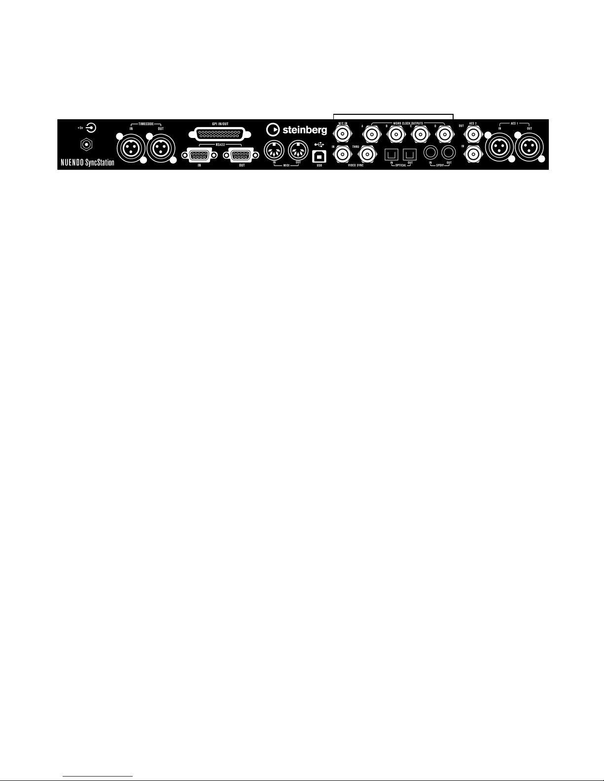
The inputs and outputs on the SyncStation rear panel
LTC GPIO
MIDI USB
Word clock AES 2
RS422 Video
Sync
Toslink
Optical
SPDIF AES 1
With a basic understanding of the SyncStation functions,
connecting the hardware to your system should be straightforward. Once you have planned your system configuration
and identified the various clock sources, timecode paths
and machine control devices, you can start by connecting
the SyncStation to the host Nuendo system.
Ö The SyncStation does not need to be connected to a
host Nuendo system in order to operate. With the front
panel controls, you can change all pertinent settings and
operate the unit stand-alone. However, the extended System Link connection requires the SyncStation to be connected to Nuendo via USB in order to provide sampleaccurate sync.
USB connection
The USB port is used to connect the SyncStation to a
Nuendo host computer. The USB connection creates two
virtual MIDI ports in Nuendo which are used for sending
and receiving transport commands and timecode information. The extended System Link connection uses USB to
send position correction commands from the SyncStation
to Nuendo. It also allows you to display and alter most of
the SyncStation settings remotely in Nuendo’s Project
Synchronization Setup dialog.
Ö For complete information on the configuration of
Nuendo’s Project Synchronization Setup dialog, refer to the
documentation provided with Nuendo.
To connect the SyncStation to a host Nuendo system,
proceed as follows:
1. On the host computer, make sure that Nuendo is not
running.
USB connections can be made while the computer is on but Nuendo will
not recognize the device unless it is plugged in before Nuendo launches.
2. Connect the power to the SyncStation.
The SyncStation should be on when it is first plugged into the host’s
USB port.
3. Connect the USB cable from the SyncStation to the
host computer.
It is advisable that you do not use a USB hub for this connection as it
might affect the operation of the SyncStation.
4. Install the driver software provided with the Sync-
Station.
Steinberg’s driver software is required for error-free operation of the
SyncStation. Make sure you are using the latest driver available by following the directions found in the section “Updating the SyncStation
driver” on page 44.
5. Launch Nuendo.
6. On the Devices menu, select the Device Setup option
to check if the SyncStation appears.
The SyncStation entry can be found on the Devices list, in the Transport
category.
7. Click on the SyncStation entry to display the software
and hardware version numbers for your unit. If the version
numbers appear as all zeros, there was a problem recognizing the unit. After closing Nuendo, try powering down
and powering up the SyncStation first to see if the problem persists.
Connecting the SyncStation
14
Page 15

Ö The SyncStation has two USB identification modes:
!
“MIDI Class” and “Steinberg”. While the default setting is
“Steinberg”, it may be necessary to try “MIDI Class” in order for Nuendo to recognize the SyncStation. Refer to
“USB 05 - USB Driver” on page 36 for more information.
Frame and clock reference inputs
There are several inputs on the SyncStation that can be
used as frame or clock references to the system. Your
particular setup will determine which of these connections
you will use.
The following inputs are available:
• Video Sync In
• Word clock In
•AES 1 In
•AES 2 In
• SPDIF In
• Optical Toslink In
• MIDI In
•LTC In
• Sony P2 (9-Pin, RS422) In
Machine control
External machines can be connected to the SyncStation
using the MIDI and Sony P2 (9-Pin RS422) connections.
The RS422 In should be connected to a master controller
device that will control the selected timecode source. The
RS422 Out should be connected to any 9-Pin device that
you want to control.
GPIO (General Purpose Input Output)
The GPIO interface uses the D sub 25 pin connector on
the rear of the SyncStation. The GPIO logic can be utilized to remotely control the SyncStation, connect record
and “on air” indicator lights and other custom applications.
The pin assignment is provided in the section “Specifica-
tions” on page 42. Refer to a qualified engineer or elec-
tronics specialist to connect and use the GPIO interface.
Slave clocks (outputs)
Slave devices need to have the same clock reference as
the SyncStation. The rear panel offers multiple clock outputs to connect various devices in your system to the
SyncStation, ensuring accurate speed between devices.
The following outputs are available:
• Four separate word clock outputs, each with its own multiplier.
• AES 1 Out (XLR)
• AES 2 Out (BNC)
•SPDIF Out
• Optical Toslink Out
Each of these connections can function as a clock refer-
ence for another digital audio device.
Please note that the SyncStation back panel optical
connector can only be used for SPDIF signals (and
not for ADAT signals).
15
Connecting the SyncStation
Page 16

3
SyncStation Controls
Page 17
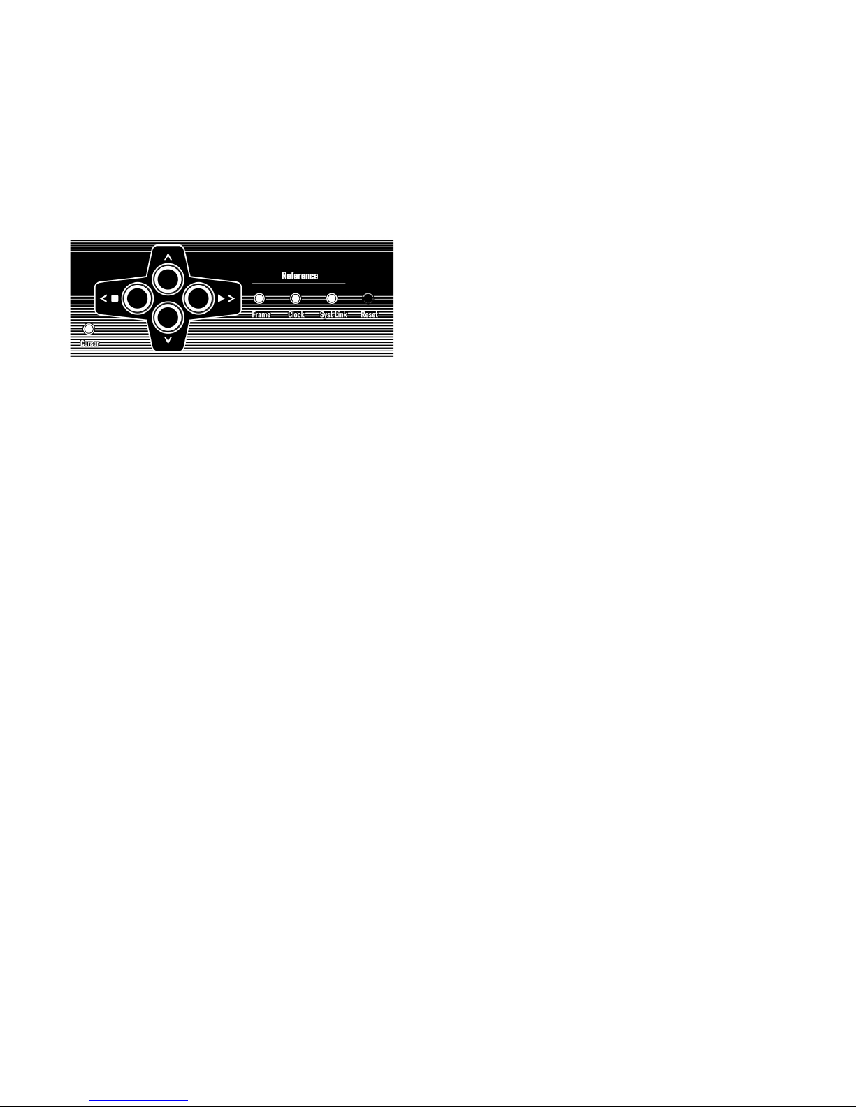
Front panel controls
Cursor buttons Status LEDs
Cursor indicator Reset button
The front panel of the SyncStation contains a two-line display, four cursor buttons, a Cursor indicator light, three status lights and a recessed Reset button.
Cursor buttons and indicator
The four cursor buttons are used to switch between the
different display options, navigate the various menus and
change SyncStation settings.
The Cursor indicator light found just below and to the left
of the cursor buttons, informs the user when the SyncStation is in Settings Menu display mode. When lit, you
can use the cursor buttons to navigate the menu system
and change settings.
When the Cursor indicator light is unlit, the up and down
arrow keys change what is seen on the second line of the
display. The left and right arrow keys function as stop and
play buttons (respectively) for the selected timecode
source.
Status LEDs
The three status LEDs on the right side of the front panel
indicate the presence of various signals and the status of
the SyncStation in relation to those signals. The indicators
are as follows from left to right:
1. Frame reference
The green LED lights up when the chosen frame reference has been detected. It will flash while the SyncStation is in the process of locking to
that signal.
2. Clock reference
When the chosen clock reference signal is present, this LED will flash orange while the SyncStation locks its sample clock to the reference and
will be solid when the unit has locked.
3. System Link
The blue LED is lit when the extended System Link connection has been
made to the SyncStation. When flashing, the Precision Timing option has
been turned on but either the System Link signal is not present or is not
in sync with the other frame and clock references.
Ö These indicator lights are duplicated in the SyncStation
Status window and Project Synchronization Setup dialog in
Nuendo.
Reset button
The Reset button resets the USB bus and the LCD screen.
This is equivalent to power cycling the unit. Nuendo must
be shut down before performing this reset of the SyncStation. Otherwise the program would loose its connection
to the SyncStation.
The left and right arrow keys generate machine control
“stop” and “play” commands that are merged with all the
other machine control transport commands and sent to
the selected timecode source device. This provides a simple way to test a configuration directly from the front panel
of the SyncStation.
SyncStation Controls
17
Page 18
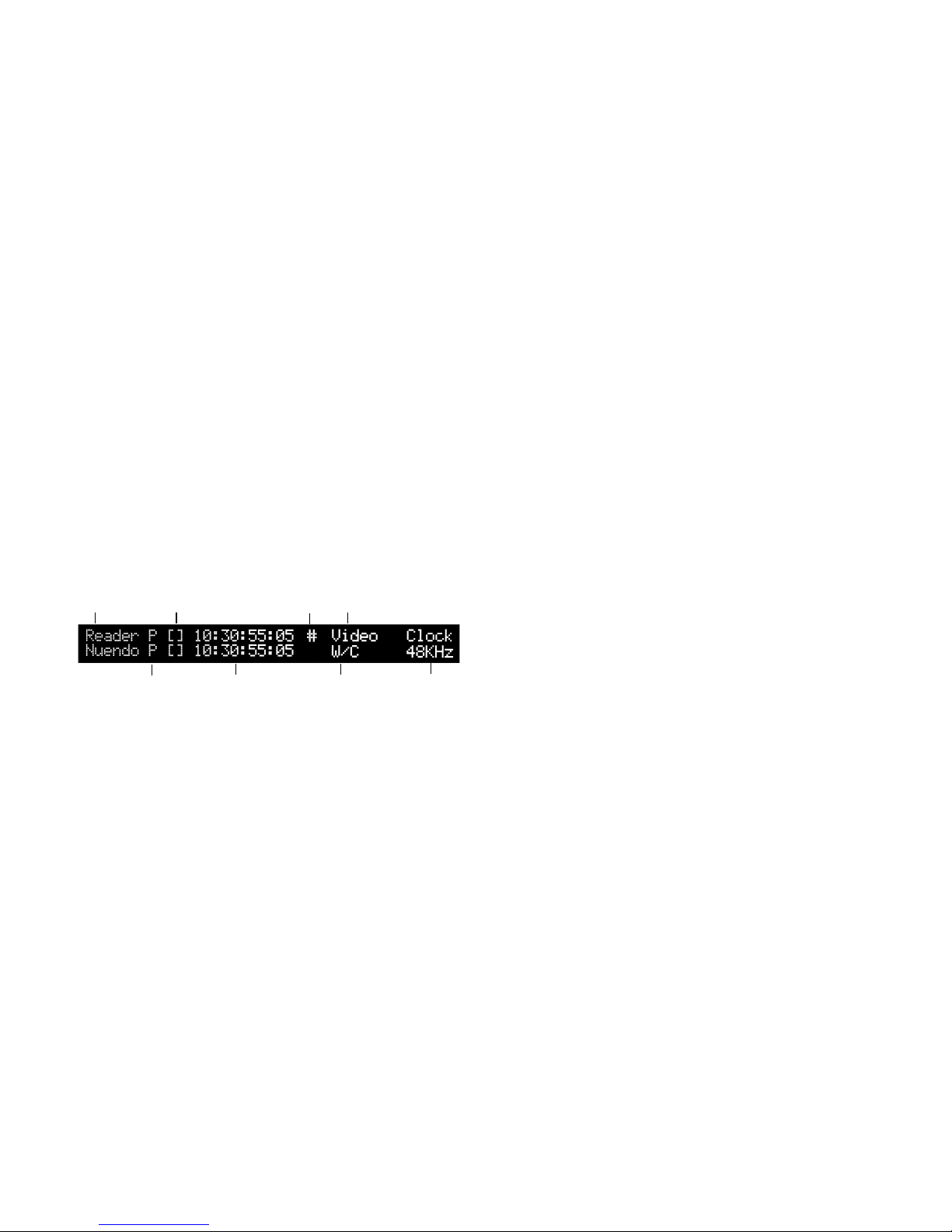
The SyncStation display
TC standard Clock
reference
Clock rateCurrent
position
USB
status
Frame reference
or frame rate
Timecode
source
Transport
status
The main display has two modes:
•Operation display
• Settings Menu display
You can use the down arrow key to switch between the
two display modes:
• Press the down arrow key for more than one second.
The cursor LED lights up, indicating that you have entered Settings
Menu display mode.
Transport status
To the right of the timecode standard, the transport status
for that timecode source is displayed using several icons:
•> = Play
•[ ] = Stop
• << = Rewind
• >> = Fast Forward
• Jg = Jog
• Sh = Shuttle
• !> = Not locked to running timecode
• Repeat this process to return to Operation display mode.
Operation display mode
The Operation display shows current timecode values for
Nuendo, SyncStation’s Virtual Machine Master, MTC,
9-Pin, and the LTC reader. It also displays the multiplier
status of the word clock outputs and the digital audio
outputs.
The top line of the display (line 1) displays the selected
timecode source device and its status.
Timecode source
Starting from the left side, the name of the timecode
source is displayed first.
Timecode standard
To the right of the timecode source name, a letter represents the current timecode standard being used by the
timecode source:
Current position
The current position for the timecode source is displayed
in the center of the screen.
USB status
Next is shown the USB status, indicated by either a # or *.
• # = USB is connected
• * = Incoming data from the host system
Frame reference or Frame rate
To the right of the USB status one of the following frame
references is displayed:
• Internal
•Video
•LTC
•MTC
If the clock reference is set to “Use Frame Ref”, this part of
the display shows the current frame rate of the timecode
source.
Ö It is possible that the timecode standard does not
match the current frame rate! This may be necessary for
some pull up/down operations or to correct for errors in
timecode use, but make sure in most conditions that the
current frame rate matches the one for the chosen timecode standard.
• P = PAL 25fps
• N = NTSC SMPTE 30fps
• D = SMPTE Drop-frame 30fps
• F = Film 24fps
18
SyncStation Controls
Page 19
Clock reference
The clock reference is shown beneath the frame reference/
frame rate on line 2 of the display. When “Use Frame Ref” is
selected, the chosen frame reference is displayed. Otherwise, the selected clock reference is shown:
•W/C
• AES 1
• AES 2
•SPDIF
•Opto
System clock rate
At the very right of the display, the system clock rate is
shown (32kHz, 44.1kHz, or 48kHz). When set to these
standard clock rates, the top line reads “Clock” and the
bottom line shows the sample rate.
• RS422
This will display the status of the device connected to the RS422 output.
If there is nothing connected, the display will show “!No Machine”.
Settings Menu display mode
To alter the SyncStation settings, you must enter the Settings Menu display mode. This is described in the section
“The SyncStation display” on page 18.
In Settings Menu display mode all of the SyncStation’s
settings can be accessed via the front panel controls using the menu system and cursor navigation. When you
first enter the Settings Menu display mode, the Root menu
is displayed.
When using a pull up/down or varispeed setting, the top
line reads “Pull” and the bottom line shows the percentage
of speed change (+4.17%, -0.1%, etc). For more information on how to use pull up/down and varispeed settings,
see “Clock 03 - Audio Pull/Varispeed 0.1%” on page 27
and “Clock 04 - Audio Pull/Varispeed 4%” on page 28.
Ö The range of varispeed is +12.5% to -12.5%.
Line 2 display
Using the up and down arrow keys, the Line 2 display can
show the timecode and status for one of the following:
• Blank
Line 2 will display different kinds of status information, e. g. GP In commands.
• Nuendo
This will display the current position, timecode standard and transport
status of the connected Nuendo system.
• Clock outputs status
When selected, both lines of the LCD are used to display the status of
the four word clock outputs plus the AES output, System Link port and
the clock rate of the SyncStation.
• Reader (LTC)
The status of the LTC reader.
The Settings Menu display
Root menu
The Root menu helps organize settings as they relate to
the various parts of the SyncStation. Using the left and
right cursor keys, you can navigate to each of the rootlevel menus. The down arrow key will step through each of
the setting menus. The up arrow key will return you to the
root level, stepping back through each setting menu.
The six root-level menus are the following:
•Unit
•Clock
•P2 Out
•P2 In
•MIDI
•USB
Each root-level menu contains settings that relate to the
category heading. For more information on the options
available in each menu, see the chapter “Menu Reference”
on page 21.
• Virtual Master
The internal timecode generator’s status.
• MTC
Status of incoming MTC.
19
SyncStation Controls
Page 20
Changing Settings
!
Track arming
buttons
Timecode
position
Record arming
destination
Transport
destination
Online button Transport controls Auto-Edit
Once you have navigated to the appropriate menu, the left
and right arrow keys are used to change settings. In order
to make changed settings active, exit the Settings Menu
display mode and return to Operation display mode.
When the SyncStation is connected to Nuendo, making changes to settings via the front panel may create
conflicts with the settings made within Nuendo.
The track arming buttons put record tracks on the remote
device into record status. Each button will light red when a
track is in record.
Auto-Edit
Most VTRs support Auto-Edit mode where the deck will
automatically enter record on record-enabled tracks at a
given timecode value and stop recording at another timecode value. The record in and out points are defined by
the left and right locators in Nuendo.
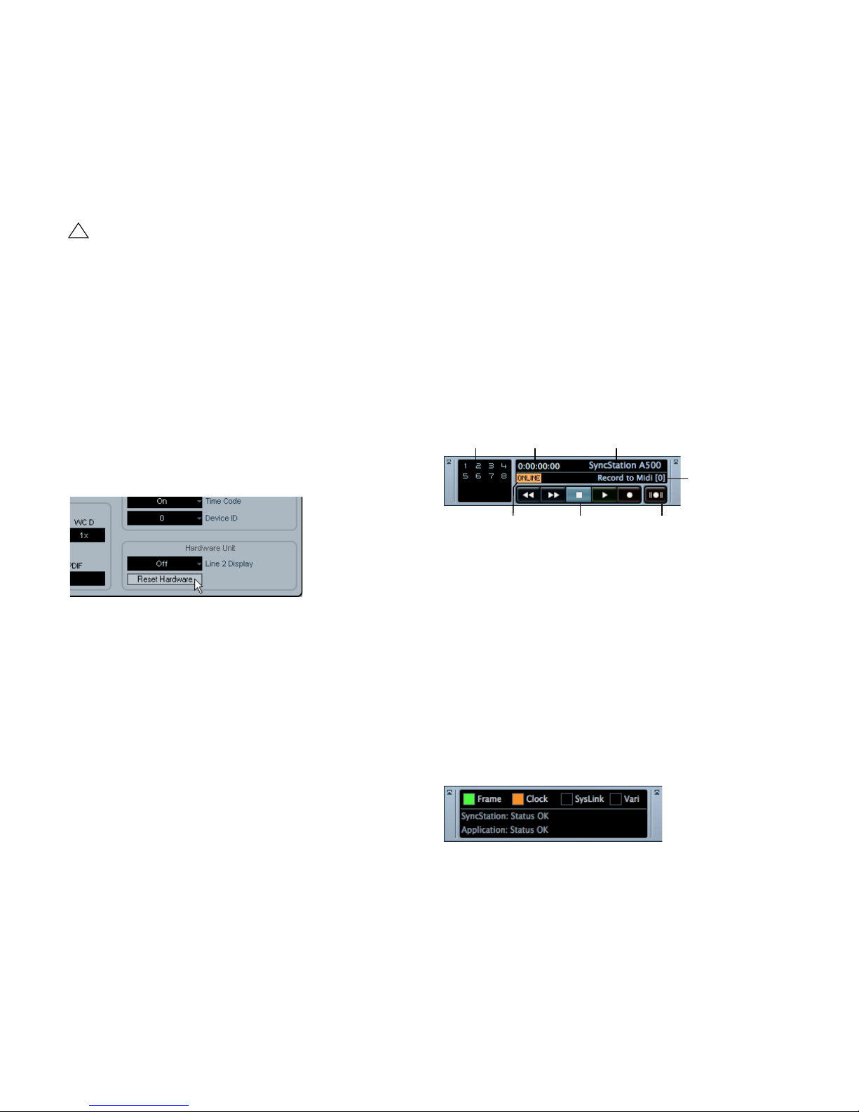
Resetting the SyncStation from
Nuendo
In a situation where you need to reset the SyncStation
hardware, you can do so from the SyncStation Settings
pop-up window by pressing the Reset Hardware button in
the Hardware Unit section. This will reboot all the SyncStation’s systems except the USB driver and LCD screen.
This reset will maintain the USB connection to Nuendo so
restarting the application is not necessary after a reset.
The Reset Hardware button
If for some reason, the USB bus and LCD need to be reset, press the Reset button on the front panel, see “Reset
button” on page 17.
The SyncStation 9-Pin window in
Nuendo
On the Devices menu in Nuendo, there is a “SyncStation
9-Pin” option. It opens a window that provides direct machine control over the SyncStation and devices connected
to its MIDI and RS422 Out ports.
When sync is engaged in Nuendo’s transport panel, recording commands will be routed to the record arming destination device. If that device is a VTR that supports autoedit, the deck will enter record at the left locator and stop
recording at the right locator. This facilitates automatic layback of audio to specific timecode values on the VTR.
SyncStation 9-Pin window
The SyncStation Status window in
Nuendo
The SyncStation Status window in Nuendo is available
from the Devices menu. It duplicates the status LEDs of the
SyncStation front panel and features a Varispeed indicator
and two status lines that display the current state of both
the SyncStation and Nuendo. An “H” on the Frame indicator is shown if the SyncStation is receiving an HD video
signal. A question mark on any of the indicators means that
the corresponding LED on the SyncStation is flashing.
Transport controls in this window are used to remotely
control a RS422 device, MIDI Machine Control device or
the internal Virtual Master. Pressing the Online button
connects the transport controls to the remote device, allowing you to control its transport functions.
Various messages regarding the status of the SyncStation
will be displayed here including precision alignment
changes and generator lock status.
20
SyncStation Controls
Page 21

4
Menu Reference
Page 22

The following table shows the entire menu organization for visual reference:
Unit Clock P2Out P2In MIDI USB
01–Master & Timecode
Source
02–Frame Reference 02–System Clock Rate 02–Position Request 02–RS422-In
03–Timecode
Standard
04–Reference
Frame Rate
05–System Link 05–Wordclock A 05–USB Driver
06–System Link Input 06–Wordclock B
07–Install Template 07–Wordclock C
08–Line 2 Display 08–Wordclock D
01–Clock Reference 01–Record Tracks 01–Device ID 01–MTC -> MIDI Out 01–MTC -> Nuendo
03–Audio Pull/Varispeed 0.1%
04–Audio Pull/Varispeed 4%
09–AESA/AESZ
Outputs
10–Opto/SPDIF
Output
11–Wordclock
Input Rate
Track Arming
03–Position From 03–MIDI In
02–Full Position ->
MIDI Out
Track Arming
04–MIDI ID 04–Nuendo MIDI ID
02–Full Position
-> Nuendo
03–Nuendo
Track Arming
Following this overview of the menu system, each menu and its settings will be reviewed and explained. Most of the
SyncStation’s settings can also be changed within Nuendo using the available settings window when the SyncStation is
selected as the Timecode Source in the Project Synchronization Setup dialog. Following the description of each menu,
the equivalent setting within Nuendo will be described.
22
Menu Reference
Page 23

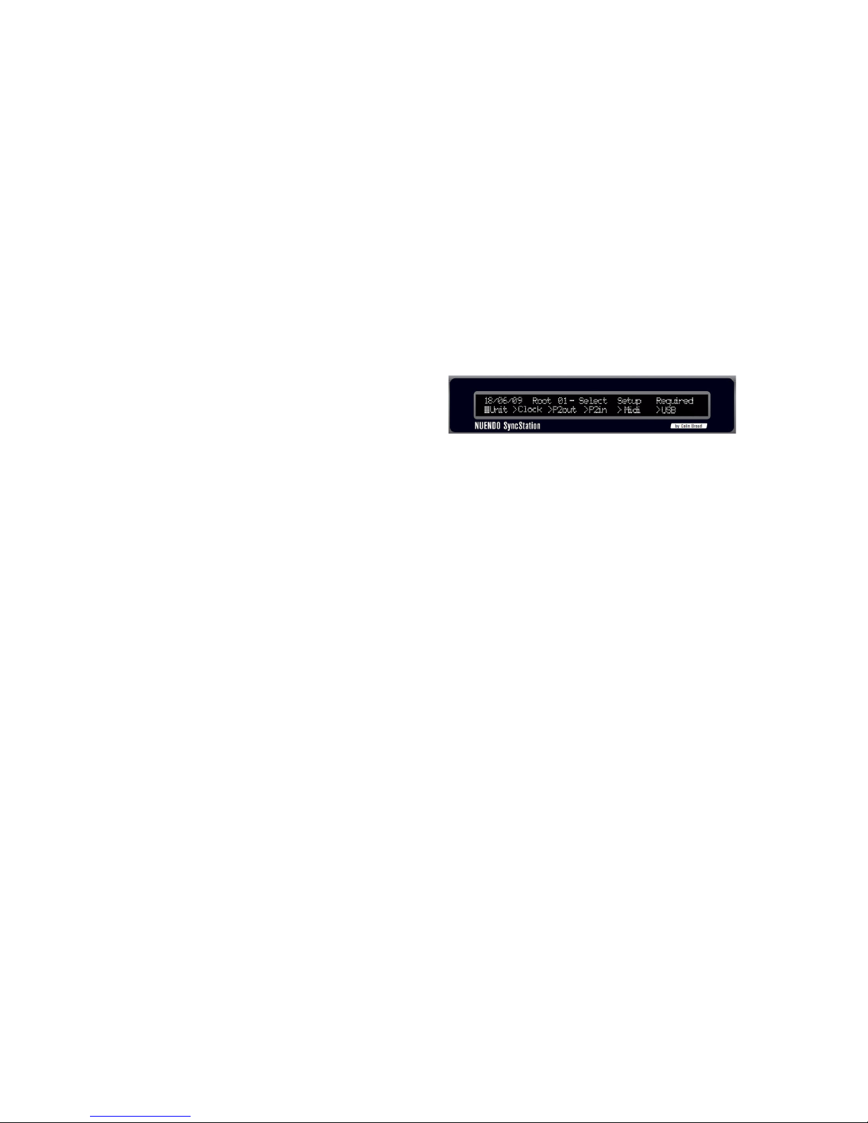
Root menu
Unit menu
DD/MM/YY Root Select Setup Required
>Unit >Clock >P2out >P2in >MIDI >USB
The root-level menu allows you to navigate between the
various menus. Since this is for navigation only, there is no
equivalent in Nuendo’s Project Synchronization Setup
dialog.
Ö Note that the date shown at the top left corresponds
to the installed firmware version.
The Unit menu deals with the basic SyncStation settings
and how timecode is generated in the unit.
Unit 01 - Master & Timecode Source
Unit 01-Master & Timecode Source
>Nuendo >RS422-Out >MTC >VMast >LTC
This is perhaps the single most important setting of the
SyncStation. This determines the timecode source. In
stand-alone mode it also determines where all the transport machine control commands will be routed. (In Nuendo
it is possible to set a different machine control destination.
See the Operation Manual for details.)
There are five choices for the timecode source:
>Nuendo
When Nuendo is selected as the timecode source, the
SyncStation will generate timecode based on the position
of the cursor in the Project window and what the current
Project Setup settings are regarding the standard and
frame rate of Nuendo’s timecode. All transport commands
will be routed to Nuendo via USB. The Machine Control
Input must be set to SyncStation in order for Nuendo to
receive these commands.
>RS422-Out
When using the RS422 Out as the timecode source, the
SyncStation will lock to timecode that a connected 9-Pin
device is being polled for. In order to have Nuendo control
this device, the Machine Control Output in the Project
Synchronization Setup dialog will have to be sent to the
SyncStation’s RS422 Out port and “sync” must be enabled in Nuendo.
>MTC
MIDI timecode can be the master timecode source. The
SyncStation will lock to MTC received from the MIDI In
connector.
>VMast (Virtual Master)
In this mode, the SyncStation’s internal timecode generator
will be the master timecode source. The SyncStation acts
like a virtual device and responds to machine control commands arriving from Nuendo via USB, MMC on the MIDI In
connector, or RS422 commands from the 9-Pin input.
23
Menu Reference
Page 24
>LTC
!
>Video
Analog timecode coming into the SyncStation via the XLR
timecode input will be used as the master timecode source.
When LTC is selected as the timecode source, machine control transport commands cannot be routed
to any device (in stand-alone mode).
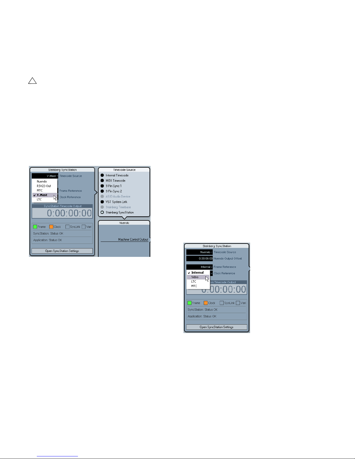
Setting the timecode source in Nuendo
Once the SyncStation has been chosen as the Timecode
source within the Project Synchronization Setup dialog, all
of the SyncStation settings become available to the left of
the Timecode Source section. You can choose a timecode source for the SyncStation from the pop-up menu in
the Steinberg SyncStation section.
Using a bi-level or tri-level video sync signal as a frame reference is the best way to ensure proper synchronization
with other video equipment. This is the primary function of
the SyncStation, using a video sync source to generate accurate timecode and sample clock for Nuendo workstations and other digital audio equipment.
>LTC
When necessary, the LTC input can be used as a frame
reference. Analog timecode is not a good stable source
for a frame reference but in certain situations, it might be
the only reference available. If you are trying to synchronize to an analog tape machine that is free running with
timecode recorded on a track, using LTC as a frame and
clock reference will allow you to lock to it.
>MTC
Due to MTC’s inherent timing issues, it should only be
used as a frame reference as a last resort.
Changing the frame reference in Nuendo
In Nuendo’s Project Synchronization Setup dialog simply
choose one of the frame reference options from the popup menu.
Choosing a timecode source for the SyncStation from the Project
Synchronization Setup dialog.
Unit 02 - Frame Reference
Unit 02-Frame Reference
>Internal >Video >LTC >MTC
The frame reference for the SyncStation is used to align
each frame in the timecode generator and also measure
the offset for the extended System Link connection to
Nuendo. This is the key to synchronizing with video.
>Internal
When the SyncStation is using the internal crystal-locked
clock as a frame reference, the system can operate in a
stand-alone fashion, without any external inputs.
Menu Reference
Choosing a frame reference for the SyncStation.
24
Page 25

Unit 03 - Timecode Standard
Unit 03-Timecode Standard
>Pal >NonDrop >Film >Drop
The timecode standard determines the frame count that
the SyncStation will use. This is not to be confused with
the frame rate or speed of the video reference signal.
>Pal (P in SyncStation display)
25 frames per timecode second.
>NonDrop (N in SyncStation display)
30 frames per SMPTE second. NTSC standard. Usually
runs at a frame rate of 29.97fps.
>Film (F in SyncStation display)
24 frames per timecode second. Also used for 24p HD
video.
Unit 05 - System Link
Unit 05-System Link
>Off >On
This setting activates the Precision Time Alignment for
sample-accurate sync to the video frame edge.
>Off
The extended System Link is not active. The SyncStation
will still provide excellent sync, just not sample-accurate to
the frame edge.
>On
When the extended System Link is activated, the SyncStation will receive sample-accurate timing information
from Nuendo and compare that with the frame reference
to generate a correction that will precisely align playback
to the sample.
>Drop (D in SyncStation display)
Still 30 frames per SMPTE second, but specific frame numbers are skipped in order to bring the timecode clock in line
with real-time while the frame rate is 29.97fps NTSC.
The SyncStation recognizes the timecode standard coming from Nuendo, MIDI In, RS422 In, and LTC In. Depending on the standard, either a F, P, N, or D is displayed next
to the timecode source name on the LCD. This setting
changes the standard for the SyncStation’s Virtual Master
if it is running stand-alone and not connected to a Nuendo
system. If the frame reference is set to Internal and the
SyncStation is connected to Nuendo, the Virtual Master
will follow Nuendo’s Project Setup settings.
Unit 04 - Reference Frame Rate
Unit 04-Reference Frame Rate
>25 >30 >24 >24.98 >29.97 >23.98
The SyncStation automatically recognizes the frame rate
coming from Nuendo and will match the setting made in
the Project Setup dialog. Any changes made to this setting will only be effective if the SyncStation is not connected to Nuendo and running in stand-alone mode.
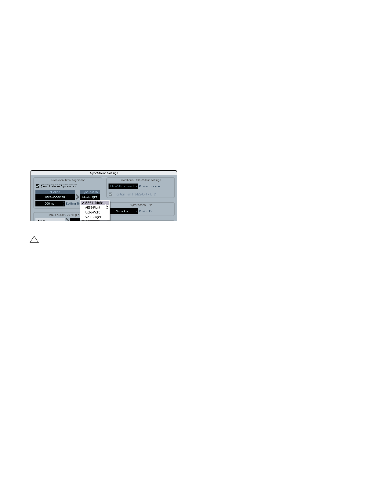
Setting up System Link from Nuendo
In the Project Synchronization Setup dialog, click the
“Open SyncStation Settings” button to reveal more settings. Select the “Send Data via System Link” option to
turn the extended System Link on. Once System Link is
turned on, you will see options for setting up outputs from
your audio cards and inputs to the SyncStation.
Unit 06 - System Link Input
Unit 06-System Link Input
>AES1 >AES2 >Opto >SPDIF
When System Link is active in the SyncStation, one of the
four digital audio ports must be selected to receive the
signal from Nuendo.
>AES 1
The AES 1 input uses the XLR input on the SyncStation.
System Link signals will always be sent on the right channel for all audio inputs.
>AES 2
This AES input uses the BNC input. BNC connections
with coaxial RG59 or higher resolution cable can be run
over greater distances than XLR balanced lines. This facilitates remote placement of the SyncStation in the machine room of larger facilities. A transformer adapter may
be used to convert XLR AES signals to BNC Coaxial.
25
Menu Reference
Page 26
>Opto
!
The Toslink Optical input. This is a stereo AES Toslink input and not an ADAT Lightpipe compatible one.
>SPDIF
The consumer digital audio connection using the RCA input will be used for System Link.
Choosing the SyncStation System Link input in Nuendo
Pop-up menus in the SyncStation Settings pop-up window let you choose the System Link input used on the
SyncStation. You must also choose an output from your
audio card that will be connected to the SyncStation’s
digital input by using the Nuendo pop-up menu.
Clock menu
This menu deals with the audio clock and how it is handled in the SyncStation.
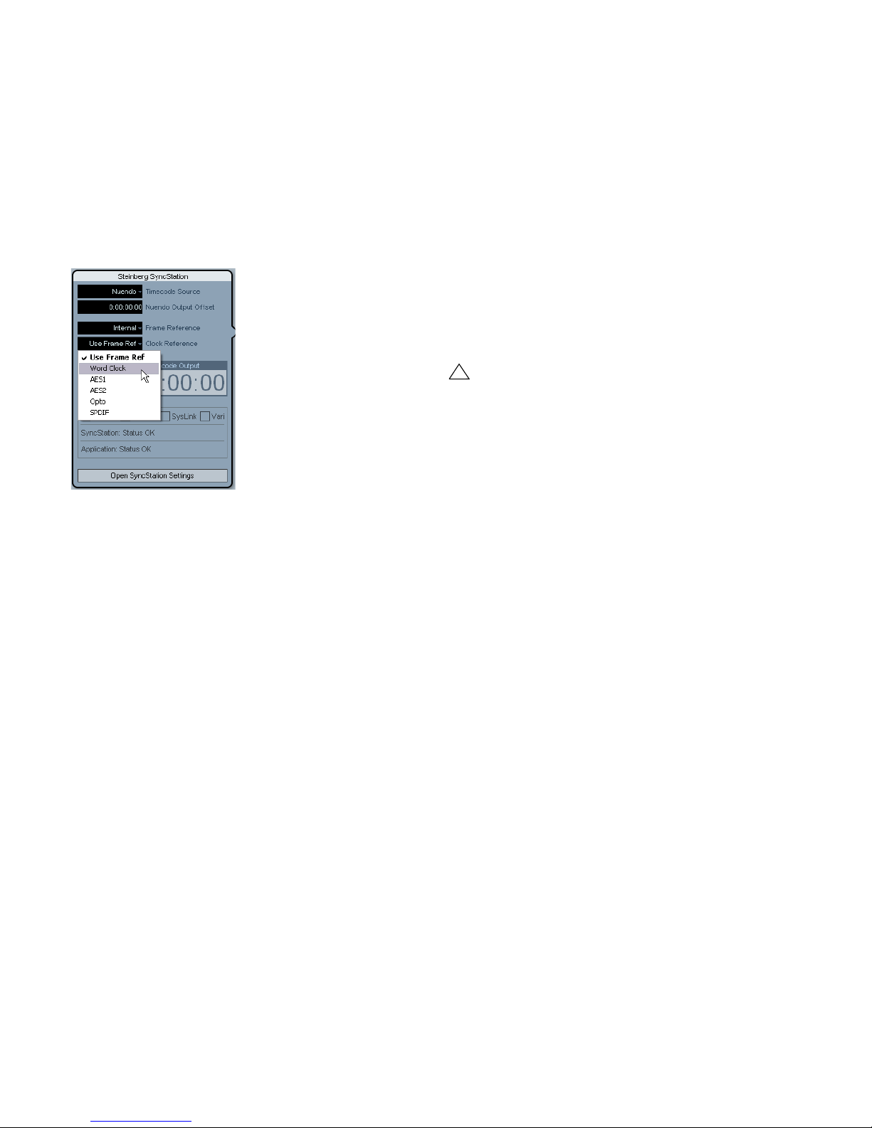
Clock 01 - Clock Reference
Clock 01-Clock Reference
>Frm >W/C >AES1 >AES2 >Opto >SPDIF
The clock reference is used to generate all the audio clocks
coming out of the SyncStation. This is critical to the audio
performance of any studio system. The optimal situation is
to have a central clock generator that outputs video sync
and audio word clock together from a single crystal clock
generator. Then you can use the word clock input as the
clock reference for the SyncStation, ensuring the best possible audio performance.
There are, however, many situations where the ideal is not
possible. Even if only LTC or MTC is available, the SyncStation can use it as both a frame and clock reference, allowing you to provide the best possible sync in any
condition.
Choosing a digital input for System Link.
The SyncStation always uses the right channel of the
selected digital input for System Link.
Unit 07 - Install Template
Unit 07-Install Template
>No Change >Factory >Test
This is used to recall the factory settings and for testing
purposes. Do not change this setting unless you want to
recall the factory settings.
Unit 08 - Line 2 Display
Unit 08-Line 2 Display
>Normal >SL >TC >DDR >TCG >USB >Frm >A1 >A2
This setting should be set to Normal as the other options
are only used for debugging and testing.
>Frm (Use Frame Reference)
This setting uses whatever signal is chosen as the frame
reference to derive the audio clock. If a high-quality video
sync is used as a frame reference, the derived audio clock
can be quite good and provide excellent sync. If only one
signal is available to the SyncStation, use this option to
utilize that signal for all references.
>W/C (Word Clock)
This is the ideal clock reference. The word clock needs to
be derived from the same source as the frame reference
for proper operation.
>AES 1
Uses the AES XLR as the clock reference.
>AES 2
Uses the AES BNC as the clock reference.
>Opto
Uses the Toslink Optical input as the clock reference.
26
Menu Reference
Page 27
>SPDIF
!
Uses the SPDIF input as the clock reference.
Setting the clock reference in Nuendo
In the Project Synchronization Setup dialog, you can
choose one of the six Clock Reference options from the
Steinberg SyncStation section.
Choosing a clock reference for the SyncStation.
Clock 02 - System Clock Rate
Clock 02-System Clock Rate
>48kHz >44.1kHz >32kHz
The SyncStation runs internally at one of three clock rates
or sample rates. Other sample rates are derived from
these base rates through the use of multipliers.
>48kHz
This is the standard video and film sampling rate. Most audio post studios will use this as the standard operating
clock rate.
>44.1kHz
This is the audio CD standard sampling rate and is used
mostly for music recording. There are exceptions and certain video productions might use this rate for certain applications.
>32kHz
You never know when you might need this sample rate.
Even though it is not a professional standard in common
use today, it is included to provide comprehensive support
for legacy devices.
Ö The SyncStation uses a multiplier system to achieve
high-resolution clock rates, see “Word clock” on page 10
for details.
Clock rate in Nuendo
When the SyncStation is connected to Nuendo and the
clock is not derived by any other signal (Frame Reference
set to Internal and Clock Reference to Use Frame Ref),
the clock rate will be determined by the Project Setup settings. If the sample rate is above 48kHz, the SyncStation
will choose the rate that is an even multiple of the project’s
rate. For example, if the project is running at 96kHz, the
SyncStation will be set to 48kHz.
If you are using higher sample rates, you will have to
properly set the word clock and AES/SPDIF output
multipliers to ensure your devices are getting correct
clock rates.
Clock 03 - Audio Pull/Varispeed 0.1%
Clock 03-Audio Pull/Varispeed 0.1%
>Off >-0.1% >+0.1%
When dealing with audio transfers from a film shoot, it can
be necessary to pull the audio clock down by 0.1% in order to match the speed change resulting from a film transfer to NTSC video. Or you might be correcting for a poorly
performed transfer and have to pull-up the clock rate.
Ö There are two audio pull settings in SyncStation, one
for 0.1% and another for 4%. The combination of the two
pull settings yields all the possible pull-up and pull-down
settings.
>Off
The audio clock runs at the chosen rate.
>-0.1%
The audio clock is slowed by 0.1%. For example, using
48kHz as the clock rate with a -0.1% pull-down results in
a sample rate of 47.952kHz.
>+0.1%
The audio clock is sped up by 0.1%. 48kHz pulled-up
yields 48.048kHz.
27
Menu Reference
Page 28
Clock 04 - Audio Pull/Varispeed 4%
!
!
Clock 04-Audio Pull/Varispeed 4%
>Off >-4.0% >+4.1667%
4% pulls are most often associated with PAL video transfers. For example, when transferring PAL video to film, a
-4% pull down is applied to achieve 24fps.
Varispeed in Nuendo
It is possible to run the SyncStation in full varispeed mode.
This gives you the option to vary the clock speed ±12.5%
in increments of 0.1%. In this state, the SyncStation cannot lock to timecode and the clock generator will run independently of the clock reference.
>Off
The audio clock runs at the chosen rate.
>-4.0%
Used for PAL video to film.
>+4.1667%
Used for film to PAL video.
There might be situations where you need to use a combi-
nation of both 4% and 0.1% pulls to correct for a problem. The SyncStation allows you the flexibility to do just
that.
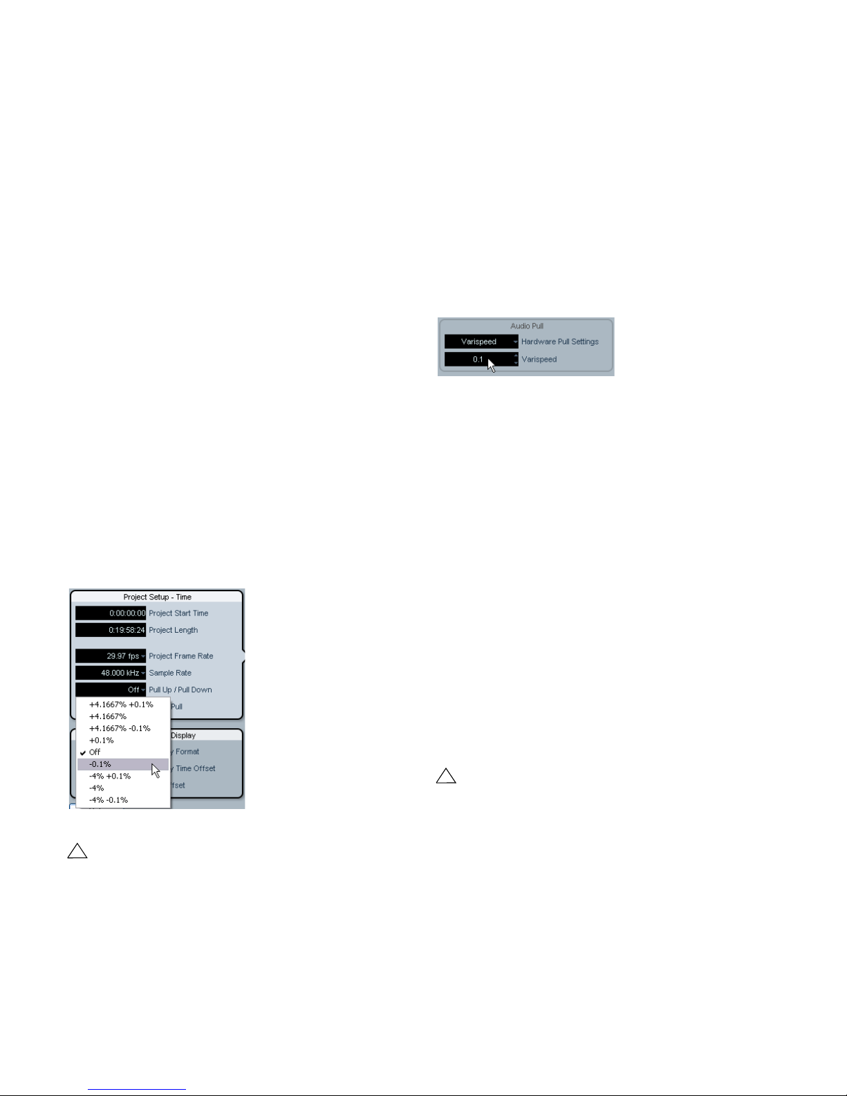
Audio pull in Nuendo
Nuendo’s Project Setup settings include a “Pull Up/ Pull
Down” menu to make the pull settings. The various combinations are made in Nuendo with single choices instead of
separate settings for 4% and 0.1% pulls.
Varispeed is accessed from the SyncStation Settings popup window in the Audio Pull section. Choose Varispeed
from the “Hardware Pull Settings” pop-up menu and enter
a varispeed amount in the field below.
Varispeed setting in the SyncStation Settings pop-up window
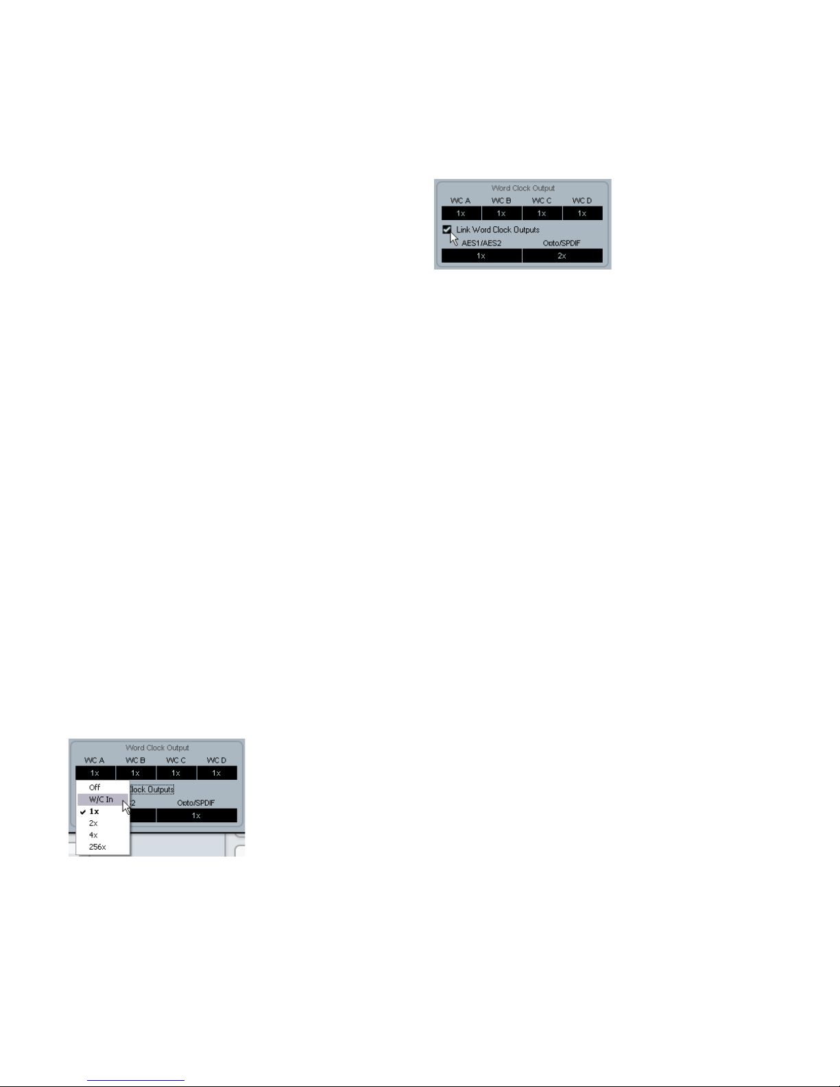
Clock 05 - Wordclock A
Clock 05-Wordclock A
>Off >W/C In >1x >2x >4x >256x
The Clock 05 to Clock 08 settings deal with the way the
clock is generated at the word clock outputs. Each output
can be individually configured to provide much flexibility
for various studio setups.
>Off
When set to “Off”, that word clock output will not have
any signal at all.
>W/C In
Audio pull in the Project Setup section
The Nuendo pull up/down settings will only be transmitted to the SyncStation if the “Hardware Pull Settings” option is set to “Follow Nuendo” (SyncStation
Settings pop-up window, Audio Pull section).
When the word clock output is set to “W/C In”, it will echo
whatever word clock signal is coming in via the word clock
input. This is important when you are using the word clock
input as the clock reference. For the best audio fidelity,
use this option in order to have the cleanest word clock
signal pass through the SyncStation to your audio device.
When using the word clock input as the clock reference, it is necessary that the incoming word clock
signal is generated by the same clock source as the
chosen frame reference or at the very least is tied to
the frame reference by another device. The best example of this is using one generator to create both
the video sync and word clock signals.
28
Menu Reference
Page 29
>1x
When set to 1x, the word clock output signal is generated
by the SyncStation and referenced to the chosen clock reference. It will run at the rate set in “Clock 02 - Clock Rate”.
>2x
The 2x setting multiplies the master clock rate in the SyncStation to output a rate twice as fast. If the clock rate is set
to 48kHz, the word clock output would run at 96kHz for
example.
All four word clock outputs can be linked together so that
changing the setting of one output affects all others in the
same way.
Word clock output link
>4x
The 4x setting allows word clock output rates up to
192kHz.
>256x
The 256x multiplier is a special use for synchronizing
Digidesign hardware units that use this proprietary word
clock signal.
Clock 06 - Wordclock B
Settings for the second word clock output.
Clock 07 - Wordclock C
Settings for the third word clock output.
Clock 08 - Wordclock D
Settings for the fourth word clock output.
Changing the word clock output in Nuendo
In Nuendo’s Project Synchronization Setup dialog, click
the “Open SyncStation Settings” button to access the
word clock output settings.
Clock 09 - AES 1/AES 2 Output
Clock 09-AES1/AES2 Output
>Clk Ref I/P >Slink I/P >1x Clk >2x Clk
The two AES outputs can be set to follow the clock reference input, the System Link input or the internal generator
running at 1x or 2x rates.
>Clk Ref I/P (Clock Reference)
The AES clock will be generated from the clock reference
input as set in menu Clock 01.
>Slink I/P (System Link Input)
The AES clock will be generated from the System Link input set in menu Unit 05. The extended System Link does
not have to be active in the SyncStation. However, other
System Link signals will be passed from the AES inputs to
the outputs so that normal System Link operation is possible through the SyncStation.
>1x Clk (Clock)
The AES output will be generated by the SyncStation at
the master clock rate.
>2x Clk (Clock)
SyncStation Settings pop-up window with “Word Clock Output”
setting menu
The AES output will run at twice the master clock rate.
29
Menu Reference
Page 30

Setting the AES clock outputs in Nuendo
!
>2x
The AES clock output setting can be found below the
“Word Clock Output” settings in the SyncStation Settings
pop-up window.
The AES output settings
Clock 10 - Opto/SPDIF Output
Clock 10-Opto/SPDIF
>Clk Ref I/P >Slink I/P >1x Clk >2x Clk
The SPDIF and Toslink outputs can have a separate setting from the two AES outputs with the same choices for
clock generation (see above). Both outputs will use the
same setting.
• Clk Ref I/P
• System Link I/P
•1x
•2x
88.2 or 96kHz rates divided by two equal 44.1 and
48kHz, respectively.
>4x
172.4 or 192kHz rates when divided by four yield 44.1 or
48kHz respectively.
>256x
The 256 divider is for Digidesign Superclock only.
Changing the clock input divider in Nuendo
In Nuendo’s Project Synchronization Setup dialog, this
option only becomes available when word clock is chosen
as the clock reference.
Setting the word clock input divider.
Please note that the SyncStation back panel optical
connector can only be used for SPDIF signals (and
not for ADAT signals).
Setting the Opto/SPDIF outputs in Nuendo
The Opto/SPDIF output setting can be found right next to
the AES settings in the SyncStation Settings pop-up window (see above).
Clock 11 - Wordclock Input Rate
Clock 11-Wordclock Input Rate
>1x >2x >4x >256x
When using the word clock input as the clock reference, it
may be necessary to determine its input divider if using
word clock rates above 48kHz.
>1x
44.1 or 48kHz standard rates do not need a divider.
Menu Reference
30
Page 31

P2 Out menu
!
The P2 Out menu determines how the RS422 output handles various aspects of the 9-Pin device.
P2out 01 - Record Tracks
P2out 01-Record Tracks
>Off >8 >16 >24 >32 >40 >48 >56 >64
The user can set the amount of record tracks available
from the 9-Pin device if the SyncStation has not automatically determined the number from polling the device.
The amount of record tracks determines how many recordenable buttons are available on the SyncStation 9-Pin device panel in Nuendo. Due to the menu structure of the
SyncStation, you are limited to nine choices:
>Off
No track arming buttons will be available on the SyncStation’s 9-Pin device panel when this is set to off.
The SyncStation will normally determine the amount
of record tracks automatically for you by polling the
device and using its internal reference of machine
descriptions.
>8 … >64
Use these settings to set the corresponding number of
tracks.
P2 audio track count in Nuendo
P2out 02 - Position Request
P2out 02-Position Request
>LTC >VITC >L+V >Tim-1 >L+T+V
The RS422 protocol uses a question-and-answer polling
system to determine the location of the connected device.
When asking the question “Where are you?” to the 9-Pin
device, it can use several internal sources to get an answer. That answer is then returned via the RS422 connection to the SyncStation.
In certain cases, it might be necessary to instruct the device to only answer using specific internal sources. This
menu setting determines what those internal sources are.
>LTC
Most VTRs have an LTC source as part of the tape format.
It can be read internally and then communicated back via
RS422 to the SyncStation.
>VITC
This is the most accurate form of timecode since it is
physically tied to the video frame signal.
>L+V
This uses a combination of LTC and VITC.
>Tim-1 (Timer 1)
Timer 1 is yet another source of location information inside
VTRs. Only in certain circumstances would you want the
position request to come only from the Timer 1 source.
64 tracks is the maximum for track arming through the
SyncStation. Even though you are limited to eight choices
in the SyncStation, in Nuendo you can set any amount of
record tracks by clicking in the audio track count field of the
“Machine Control Output Settings” section in the Project
Synchronization Setup dialog.
Entering the amount of tracks for the RS422 output device.
Menu Reference
>L+V+T
This is the default setting and uses a combination of all
three sources for a position request.
31
Page 32

Position request setting in Nuendo
In Nuendo, you can access this setting by selecting an option from the “Position source” pop-up menu in the SyncStation Settings pop-up window.
P2 In menu
The RS422 input is used to remotely control the SyncStation as a virtual machine from an external master controller. When enabled, the SyncStation will appear as
another 9-Pin device to the external controller.
P2in 01 - Device ID
P2in 01-Device ID
>RS422-Out >Nuendos >Nuendot >3324 >A500
The external controller will identify the SyncStation by the
ID set in this menu.
>RS422-Out
Selecting the RS422 position request sources.
P2out 03 - Position From
P2out 03-Position From
>Serial >Serial+LTC Reader
This is an extension of the position request setting, allowing you to also use the LTC reader in the SyncStation as a
source of position information when the timecode source
is set to RS422 Out. While the serial 9-Pin connection
can communicate position using LTC internally, the addition of the SyncStation’s LTC reader can be useful in certain situations where there is an issue.
>Serial
This uses the serial 9-Pin RS422 connection exclusively
for position requests.
>Serial+LTC Reader
This allows the LTC reader to be used as another source
of position information for the SyncStation when RS422 is
set as the timecode source.
Position from setting in Nuendo
When set to RS422-Out, the SyncStation will identify itself to the controller as the same type of device that is
connected to the SyncStation’s 9-Pin out connector.
>Nuendos
Identifies the SyncStation as “Nuendo SyncStation”.
>Nuendot
Identifies the SyncStation as “Nuendo Timebase”.
>3324
Identifies the SyncStation as a Sony 3324 DASH Digital
Multitrack machine.
>A500
Identifies the SyncStation as a Sony A500 VTR, a very
common 9-Pin profile.
Setting the P2 In device ID in Nuendo
The P2 In device ID can be set in Nuendo from the SyncStation Settings pop-up window by selecting an entry
from the Device ID pop-up menu.
In Nuendo, this setting can be changed from the SyncStation Settings pop-up window with the “Position from
RS422-Out+LTC” check box. When deactivated, the
SyncStation will use the serial port only.
Setting the P2 In device ID to A500.
32
Menu Reference
Page 33

P2in 02 - RS422-In Track Arming
P2in 02-RS422-In Track Arming
>Nuendo >RS422-Out >MIDI Out
Since the Virtual Master of the SyncStation does not have
any tracks that can be record-enabled, those commands
received from the external controller are diverted to another destination. Additionally, when a “record” command
is received, it will also be routed to the destination set in
this menu.
MIDI menu
This menu contains settings regarding the MIDI input and
output configuration.
MIDI 01 - MTC -> MIDI Out
MIDI 01-MTC -> MIDI Out
>On >Off
This determines if MTC is being sent via the MIDI output.
>Nuendo
Record and track arming commands will be sent to
Nuendo via USB.
>RS422-Out
Record and track arming commands will be sent to the
device connected to the RS422 Out.
>MIDI Out
Record and track arming commands will be routed to the
MIDI output.
P2 In track arming in Nuendo
The track arming can be set within Nuendo from the
“Track Record Arming Routing” section in the SyncStation Settings pop-up window.
MIDI 02 - Full Position -> MIDI Out
MIDI 02-Full Position -> MIDI Out
>Off >MMC Full >Full on change >Locate
This setting deals with how MTC is relayed to the MIDI
output. MTC has two basic messages, quarter-frame and
full-frame. Full-frame messages are SysEx data that contain the complete timecode number. Full-frame messages
are used to locate devices to specific points.
Quarter-frame messages are only used during playback
and only contain a partial timecode number. It takes 8
quarter-frame messages for the complete timecode number to be transmitted. Quarter-frame messages are used
during playback to maintain sync.
This setting determines what message is sent when the
timecode source changes position in Stop mode.
>Off
No full-frame messages will be sent at all.
>MMC Full
Full-frame messages will be sent constantly.
Setting the RS422-In track arming routing to MIDI Out.
>Full on change
This is the default setting and should work for most cases.
Full-frame messages are sent when the position of the master changes, such as when locating to a new position.
During playback, only quarter-frame messages will be used.
>Locate
The MMC locate command is slightly different from “Full
on change”. Some devices will react to this mode better
than others.
33
Menu Reference
Page 34

MIDI full position setting in Nuendo
MTC, Full Position and MIDI Device ID can all be set
within Nuendo from the SyncStation MIDI section in the
SyncStation Settings pop-up window.
The MIDI settings in the SyncStation Settings pop-up window
MIDI 03 - MIDI In Track Arming
MIDI 03-MIDI In Track Arming
>Nuendo >RS422-Out
This setting is independent of the RS422 In record and
track arming, but performs the same function for MMC
commands from the MIDI input.
>Nuendo
Routes all record and track arming commands to Nuendo
via USB.
>RS422-Out
MIDI 04 - MIDI ID
MIDI 04-MIDI ID
>0 >1 >2 >3 >4 >5 >6 >7 >8 >All(7f)
This determines the MIDI device ID used by the commands sent out via the MIDI Out.
Changing the MIDI device ID in Nuendo
You can change the MIDI device ID by selecting a value
from the Device ID pop-up menu in the SyncStation Settings pop-up window.
Changing the MIDI device ID.
Routes all record and track arming commands to the
RS422 output.
MMC record and track arming in Nuendo
The MIDI track arming can be set from the “Track Record
Arming Routing” section within the SyncStation Settings
pop-up window.
Changing the routing for MIDI track record arming
34
Menu Reference
Page 35

USB menu
This menu deals with the USB connection to the Nuendo
host computer and the MIDI communication between the
SyncStation and Nuendo.
>RS422-Out
All record and track arming commands will be sent to the
connected 9-Pin device.
>MIDI Out
USB 01 - MTC -> Nuendo
USB 01-MTC -> Nuendo
>On >Off
This determines if MTC is transmitted to Nuendo via USB.
If this is set to Off, Nuendo cannot start playback because
the SyncStation will not transmit incoming timecode.
USB 02 - Full Position -> Nuendo
USB 02-Full Position -> Nuendo
>Off >MMC Full >Full on change >Locate
This determines the usage of full-frame MTC messages
going to Nuendo. Just as with the MIDI Out setting, the
“Full on change” setting will work for most conditions, but
the others are available for certain circumstances.
>Off
No full-frame messages will be sent.
>MMC Full
Constant full-frame messages will be sent.
>Full on change
Default sends full-frames only when position changes and
not during play. Using this option is recommended since it
allows you to avoid generating too much MIDI traffic.
>Locate
All record and track arming commands will be sent to the
MIDI output.
Changing the USB track arming in Nuendo
You can change Nuendo’s track arming by selecting a
value from the Nuendo pop-up menu in the “Track Record
Arming Routing¨ section in the SyncStation Settings popup window.
Setting the Nuendo track arming to MIDI Out.
USB 04 - Nuendo MIDI ID
USB 04-Nuendo MIDI ID
>0 >1 >2 >3 >4 >5 >6 >7 >8 >All(7f)
Sets the MMC ID number for Nuendo for receiving MMC
commands from the MIDI input.
Setting the USB MIDI device ID in Nuendo
The MIDI ID, MTC and Full Position settings can be made
in the SyncStation Settings pop-up window from the
SyncStation USB section.
MMC locate commands will be sent.
USB 03 - Nuendo Track Arming
USB 03-Nuendo Track Arming
>RS422-Out >MIDI Out
This setting is independent of the MIDI and RS422 track
arming settings. Track arming buttons on the SyncStation
9-Pin device panel will be routed according to this setting.
Also, record commands sent by Nuendo’s transport when
sync is enabled will be routed to the same destination.
This can be used to perform remote layback on any connected device.
Choosing a MIDI ID for Nuendo.
35
Menu Reference
Page 36

USB 05 - USB Driver
!
!
USB 05-USB Driver
>MIDI Class >Steinberg
This determines which driver the SyncStation will use to
connect to the host USB bus. The default setting is “Steinberg” but it may be necessary on some systems to use the
MIDI Class driver.
Changing the USB driver requires a restart of the
SyncStation.
Windows XP will not allow Nuendo to recognize the
SyncStation when set to the MIDI Class driver. Always use the Steinberg setting with Windows XP
systems.
Ö You cannot change the USB driver from within
Nuendo.
36
Menu Reference
Page 37

5
Example Studio Setups
Page 38

Using three example studios, we will go step-by-step
!
through the process of connecting the SyncStation in
each system.
Composer’s home studio
In this first example, a personal project studio that functions as a composer’s suite for film and television music
will be used. System Link is used to connect two audio
workstations; a main Nuendo system for editing and mixing and a Cubase system for running VSTi instruments
and external MIDI devices. A Digital Betacam VTR is used
to layback finished cues to videotape. Additionally, an Alesis HD 24 hard disk recorder is used to print stems to mix
at a dubbing theater.
• Nuendo system
• Cubase VSTi system
• Alesis HD 24 hard disk recorder
• Digital Betacam VTR
In this example, the SyncStation will be used as the ma-
ster clock source for all the audio equipment in the studio.
Each of the word clock outputs is connected to the two
audio cards for the Nuendo and Cubase systems plus another word clock connection to the HD 24. Since there is
no other video equipment involved besides the Betacam
deck, video sync will come from the VTR.
Machine control is used to control and sync with the Betacam VTR via RS422. Also, MMC is used to remotely arm
tracks on the HD 24. Since a Digital Betacam deck is
standard definition, only bi-level video sync is used as the
frame reference. Timecode from the Betacam is communicated over the RS422 protocol and will be used as the
timecode source in the SyncStation.
Extended System Link connections
Notice that there are two System Link connections, the
extended connection used by the SyncStation for sampleaccurate positioning and the normal connection between
Steinberg DAWs via the SyncStation.
Ö Note that the extended System Link connection only
goes one way, from the audio card in the Nuendo system
to one of the three digital inputs of the SyncStation.
In order to use one of the digital outputs of the SyncStation to pass System Link on to other Steinberg DAWs,
Menu Clock 09 or 10 would be set to SLink I/P in order
for System Link signals to pass through the SyncStation.
When using the extended System Link connection to
the SyncStation, all System Link settings must be
made via the SyncStation’s front panel or the SyncStation Settings pop-up window in Nuendo. The
Nuendo System Link setup in the Devices menu cannot be used while the extended System Link is engaged.
Example connections for a composer’s home studio
SyncStation settings for home studio example
• Master & Timecode Source = RS422 Out
• Frame Reference = Video
• Clock Reference = Use Frame Ref
•Wordclocks = 1x
• Precision Alignment System Link = On
• Track Arming Routing = Nuendo > RS422 or MIDI
• Nuendo Machine Control Output = SyncStation (RS422)
38
Example Studio Setups
Page 39

Mid-level post-production suite
Film dubbing theater
This example involves a dedicated audio for video postproduction studio that is involved in audio editing, foley
and voice recording, multi-channel mixing, and DVD authoring. This studio includes a high-quality computer video
card that is used to capture video and audio from a Digital
Betacam VTR. A master video clock generator is used to
ensure frame edge accurate operation from the Digital
Betacam, video card, and Nuendo.
• Nuendo system
• Virtual VTR computer with BlackMagic card
• House tri-level video sync generator
• Various VTRs via machine room router
The most complex example is a fully-fledged dubbing
stage where feature films and high-profile television
shows are mixed. This example involves dedicated video
playback for a large projection system, multiple Nuendo
and other DAW systems to handle audio playback and
surround mixing, plus a large, multi-seat control surface
for mixing including machine control and track arming for
dubbers.
• Nuendo system
• Pro Tools system
• Console’s 9-Pin controller
• Nanosync tri-level video sync and word clock generator
• Bonsai HD video player
A mid-level post-production studio with a central machine room
In this example, tri-level video sync is used to synchronize
Nuendo’s playback to the house sync generator in the machine room of the facility. The SyncStation’s RS422 output is fed into the router where it can be connected to any
VTR in the machine room.
SyncStation settings for post suite example
• Master & Timecode Source = RS422 Out for video capture
and layback or Nuendo for editing
• Frame Reference = Video
• Clock Reference = Use Frame Ref
•Wordclocks = 1x
• Machine Control Output = SyncStation (RS422)
• Precision Alignment System Link = On
• Track Arming Routing = Nuendo > RS422
Example Studio Setups
A sample dub stage setup using a RS422 master controller
In this example, Nuendo is synchronized with a Bonsai HD
video player and a Pro Tools system. All of this is controlled
by the main console’s RS422 controller, allowing the
transport controls of the console to run the entire system.
In this setup, the SyncStation is the Virtual Master, generating timecode for all devices. Both the console and
Nuendo can start and stop playback or locate the system.
The Nanosync generator is used for both the frame reference input and the word clock input. A 256x word clock is
being fed to the Pro Tools system along with MTC. Pro
Tools is also connected via RS422 Out for record-arming
tracks and punching in. The Bonsai locks to LTC and is
video gen-locked to the tri-level sync.
39
Page 40

SyncStation settings for dub stage example
• Timecode Source = Virtual Master
• Frame Reference = Video
• Clock Reference = Word clock
• Wordclocks = 1x and 256x
• Machine Control Output = SyncStation (RS422)
• Machine Control Input = SyncStation
• SyncStation P2 In = A500
• Precision Alignment System Link = On
• Track Arming Routing = Nuendo > RS422
40
Example Studio Setups
Page 41

6
Technical Data
Page 42

Specifications GPIO pin assignment
Connections 5V DC input
USB 1.1
Timecode In/Out (XLR)
MIDI In/Out
Video Sync In/Thru (BNC) SD/HD,
bi-level/tri-level signals
Word Clock In (BNC)
Word Clock Out A-D (BNC) up to 192kHz
AES In/Out (XLR) up to 96kHz
AES In/Out (BNC) up to 96kHz
SPDIF In/Out (Coax) up to 96kHz
SPDIF In/Out (Optical) up to 96kHz
RS422 In/Out (9’ D’ connector)
General Purpose In/Out interface
(25’ D’ single connector)
External
power-supply
Dimensions Front-panel 19" rack-mountable
Input AC 100- 240 V 50/60Hz 0.4A 30VA;
Output DC 5V 2 A
48.3 x 4.4 x 17.5cm
Weight 1.4kg
Display 14.7 x 1.2 cm (2x40 characters)
GPI-In Function (Active low)
3 Stop Momentary
4 Play Momentary
5 Record Off Momentary
6 Record On Momentary
7 Record Continuous
8 On-Line
9
10
GPI-Out Function (Active Low)
16
17 SyncStation Lock
18 Record Off Momentary
19 Record On Momentary
20 Record Continuous
21 On-Line
22 Nuendo Lock
Ö Wiring diagrams can be found on the Steinberg web
site at http://service.steinberg.de/goto.nsf/show/
supportupdates_syncstation_en.
42
Technical Data
Page 43

FCC information (U.S.A.)
CE Declaration of Conformity
Note: This equipment has been tested and found to comply
with the limits for a Class A digital device, pursuant to part
15 of the FCC Rules. These limits are designed to provide
reasonable protection against harmful interference when
the equipment is operated in a commercial environment.
This equipment generates, uses, and can radiate radio frequency energy and, if not installed and used in accordance
with the instruction manual, may cause harmful interference
to radio communications. Operation of this equipment in a
residential area is likely to cause harmful interference in
which case the user will be required to correct the interference at his own expense.
Changes or modifications not expressly approved by the
party responsible for compliance may void the user’s authority to operate the equipment.
Compliance Information Statement (Declaration of
Conformity Procedure)
This device complies with part 15 of the FCC Rules. Operation is subject to the following two conditions:
1. This device may not cause harmful interference, and
2. this device must accept any interference received, in-
cluding interference that may cause undesired operation.
We, Steinberg Media Technologies GmbH, Neuer Hoeltigbaum 22-32, 22143 Hamburg, Germany, declare under our sole responsibility that the product
Nuendo SyncStation
to which this declaration relates is in conformity with the
following standard(s) or other normative document(s):
Disturbance Emission
• EN 55022:1998 + A1:2000 + A2:2003
• EN 55022:1998 + A1:2000 + A2:2003
• EN 61000-3-2:2000 Limits
• EN 61000-3-3:1995 + A1:2001 Limits
• EN 55103-1:1996 magnetic field emission test
• The limits and requirements according to
EN 55103-1:1996
Immunity Interference
• EN 61000-4-11:1994
• EN 61000-4-5:1995 + A1:2001
• EN 61000-4-4:1995 + A1:2001 + A2:2001
• EN 61000-4-2:1995 + A1:1998
• EN 61000-4-6:1996 + A1:2001
• EN 61000-4-3:2002 + A1:2002
• EN 55103-2:1996
• The limits and requirements according to
EN 55103-2:1996
43
Technical Data
Page 44

Handling warranty issues
Go to www.steinberg.net/warranty to find the Steinberg
Statement of Warranty, and information on the handling of
warranty issues. This web page also contains the End
User License Agreements for Steinberg software products. All documents are available as printable PDF files.
Updating the SyncStation driver
To operate the SyncStation via the USB port of your computer, a driver software corresponding to the operating
system of your computer must be installed.
You can find this driver on the Nuendo installation disk included in your SyncStation package, in the “Drivers” folder.
The drivers are also available in the following location:
http://service.steinberg.de/goto.nsf/show/
supportupdates_syncstation_en
Be sure to check for updates at regular intervals.
A “SyncStation Driver Installation-en.txt” file explaining the
installation procedure for Windows and Mac OS computers can also be found inside the “Drivers” folder on the
Nuendo DVD, and in the following location:
http://service.steinberg.de/goto.nsf/show/
supportupdates_syncstation_en
Updating the SyncStation firmware
Steinberg supplies the firmware running in the SyncStation as a separate downloadable package in the following location:
http://service.steinberg.de/goto.nsf/show/
supportupdates_syncstation_en
A “Readme” file explaining the installation procedure for
this package can also be found in this location. Be sure to
check for updates at regular intervals.
44
Technical Data
Page 45

Index
Page 46

A
AES 10, 14, 15, 19, 26
AES clock outputs
Setting in Nuendo 30
Setting in SyncStation 29
Audio pull
Setting in Nuendo 28
Setting in SyncStation 27
Auto-Edit 20
B
Bi-level sync (video black burst) 10
C
Clock distribution 7
Clock outputs
Setting in Nuendo 29
Setting in SyncStation 28
Slave devices 15
Status on SyncStation display 19
Clock rate
On SyncStation display 19
Setting in Nuendo 27
Setting in SyncStation 27
Clock reference
Inputs 15
LED 17
LTC 10
MTC 10
On SyncStation display 19
Setting in Nuendo 27
Setting in SyncStation 26
Video 10
Clock sources 10
Current position display 18
Cursor buttons 17
Cursor LED 17
D
Display modes
About 18
Operation mode 18
Settings Menu mode 19
E
Extended System Link
About 7
Setting in Nuendo 25
Setting in SyncStation 25
USB 14
F
Factory settings (recall) 26
Film 8, 9, 18, 25
Frame count 9
See also “Timecode standard”
Frame rate
About 9
On SyncStation display 18
Frame reference
About 11
Inputs 15
LED 17
On SyncStation display 18
Setting in Nuendo 24
Setting in SyncStation 24
Front panel
Cursor buttons 17
Cursor indicator 17
Overview 17
Reset button 17
Status LEDs 17
Full/Quarter-frame messages via
MIDI
Setting in Nuendo 34
Setting in SyncStation 33
Full-frame messages via USB
Setting in SyncStation 35
G
GPIO 14
About 8
Connection 15
Pin assignment table 42
H
HD video 10, 11
I
Inputs on rear panel 14
L
LCD screen
Display modes 18
Line 2 display 19
Resetting 17
LTC 8, 10, 11, 12, 14, 15, 18, 24, 31
LTC reader 19, 32
M
Machine control
9-Pin RS422 12
9-Pin window in Nuendo 20
About 7
Connections 15
MMC 12
Track arming commands 11
Transport commands 11
Virtual Machine Master 11
MIDI device ID
Changing in Nuendo 34
Changing in SyncStation 34
MIDI In 15
MIDI In/Out 14
MIDI Machine Control 12
MIDI Out 33, 35
MIDI-In Track Arming
Setting up in Nuendo 34
Setting up in SyncStation 34
MTC 8, 10, 11, 18, 19, 23, 24, 33, 35
N
NTSC 9, 18, 25
Nuendo
Connecting to the SyncStation 14
Resetting the SyncStation 20
Status on SyncStation display 19
SyncStation 9-Pin window 20
SyncStation Status window 20
Transport commands 12
Nuendo Timebase 32
Nuendo track arming
Setting in Nuendo 35
Setting in SyncStation 35
46
Index
Page 47

O
Operation (display mode) 18
Opto/SPDIF outputs
Setting in Nuendo 30
Setting in SyncStation 30
Outputs on rear panel 14
P
P2 In device ID
Setting in Nuendo 32
Setting in SyncStation 32
PAL 9, 18, 25, 28
Phase (frame reference) 11
Position from setting
In Nuendo 32
In SyncStation 32
Position request setting
In Nuendo 32
In SyncStation 31
Position source setting 32
Precision Time Alignment 25
Pull up/down 9, 19
See also “Audio pull”
R
Rear panel inputs/outpus 14
Recall factory settings 26
Record track count
Setting in Nuendo 31
Setting in SyncStation 31
Reference frame rate
Setting in SyncStation 25
Reset button 17
Reset Hardware button in Nuendo 20
Root menu (Settings Menu display
mode) 19, 23
RS422 8, 12, 14, 15, 19, 23, 32, 33,
34, 35
RS422-In Track Arming
Setting up in Nuendo 33
Setting up in SyncStation 33
S
Sample rate, see “Clock rate”
Settings Menu
Basic settings (Unit menu) 23
Changing settings 20
Clock settings 26
MIDI In and Out settings 33
Overview of menu system 22
Root level 19
Settings for 9-Pin devices 31, 32
USB-related settings 35
Slave clocks 15
SMPTE 9, 18
Sony A500 32
Sony P2 8, 15
SPDIF 10, 14, 15, 19, 26, 27
Speed (frame rate) 9
Standard frame rates 9
Status LEDs 17
Status window in Nuendo 20
Synchronization 8
SyncStation driver 44
SyncStation firmware 44
System Link input
Selecting in Nuendo 26
Selecting in SyncStation 25
System Link LED 17
T
Technical data 41
Timecode
About 8
Frame count 9
Frame rate 9
Timecode source
Selecting in Nuendo 24
Selecting in SyncStation 23
SyncStation display 18
Timecode standard
Setting in SyncStation 25
SyncStation display 18
Timecode synchronizer 7
Toslink 15
Toslink Optical (Opto) 10, 14, 19, 26
Track arming 11
Transport status icons 18
Tril-level sync (video) 10
U
USB connection 14
USB driver
Changing in SyncStation 36
Resetting 17
USB MIDI device ID
Setting in Nuendo 35
Setting in SyncStation 35
USB status display 18
V
Varispeed 19, 27, 28
Setting in Nuendo 28
Varispeed indicator 20
Video 11, 18, 24
Video black burst 10
Video frame rate 10
Video sync 10, 11, 14, 15, 24, 26
Virtual Master 11, 19, 23, 25
VITC 8, 31
W
Warranty information 44
Word clock 10, 14, 15, 19, 26, 28
Word clock input divider
Setting in Nuendo 30
Setting in SyncStation 30
47
Index
Page 48

Benutzerhandbuch
Page 49

Benutzerhandbuch von Ashley Shepherd
Überarbeitung, Qualitätssicherung und Übersetzung: Cristina Bachmann, Heiko Bischoff, Marion Bröer, Sabine Pfeifer,
Heike Schilling
Die in diesem Dokument enthaltenen Informationen können ohne Vorankündigung geändert werden und stellen keine Verpflichtung seitens der Steinberg Media Technologies GmbH dar. Ohne ausdrückliche schriftliche Erlaubnis durch die Steinberg Media Technologies GmbH darf kein Teil dieses Handbuchs für irgendwelche Zwecke oder in irgendeiner Form mit
irgendwelchen Mitteln reproduziert oder übertragen werden.
Alle Produkt- und Firmennamen sind ™ oder ® Marken der entsprechenden Firmen. Windows XP ist eine Marke der Microsoft Corporation. Windows Vista ist eine eingetragene Marke oder eine Marke der Microsoft Corporation in den USA und/oder
anderen Ländern. Das Mac-Logo ist eine Marke, die in Lizenz verwendet wird. Macintosh und Power Macintosh sind eingetragene Marken.
Stand: 31. August 2009
© Steinberg Media Technologies GmbH, 2009.
Alle Rechte vorbehalten.
Page 50

Inhaltsverzeichnis
Page 51

52 Einleitung
53 Über dieses Handbuch
53 Was kann die SyncStation?
53 Clock-Verteiler
53 Machine Control
53 Timecode-Synchronizer
53 Erweiterte System-Link-Verbindungen für die
SyncStation
54 GPIO (General Purpose In/Out)
54 Synchronisieren mit der SyncStation
54 Grundlagen der Synchronisation
54 Timecode (Positionierungsreferenz)
56 Clock-Quellen (Geschwindigkeitsreferenzen)
57 Frame-Referenz (Phase)
58 Machine Control
60 Anschließen der SyncStation
61 Die Anschlüsse auf der Rückseite der SyncStation
61 USB-Verbindung
62 Eingänge für Frame- und Clock-Referenz
62 Slave-Clocks (Ausgänge)
62 Machine Control
62 GPIO (General Purpose Input Output)
63 Die Bedienelemente der SyncStation
64 Die Bedienelemente der Frontseite
64 Die Cursor-Tasten und die Anzeige
64 Status-LEDs
64 Reset-Taste
65 Das SyncStation-Display
65 Anzeigemodus »Betrieb«
66 Anzeigemodus »Einstellungen«
67 Zurücksetzen der SyncStation über Nuendo
67 Das Fenster »SyncStation 9-Pin« in Nuendo
68 Das Fenster »SyncStation Status« in Nuendo
75 Das Clock-Menü
75 Clock 01 - Clock Reference
75 Clock 02 - System Clock Rate
76 Clock 03 - Audio Pull/Varispeed 0.1%
76 Clock 04 - Audio Pull/Varispeed 4%
77 Clock 05 - Wordclock A
78 Clock 06 - Wordclock B
78 Clock 07 - Wordclock C
78 Clock 08 - Wordclock D
78 Clock 09 - AES 1/AES 2 Output
79 Clock 10 - Opto/SPDIF Output
79 Clock 11 - Wordclock Input Rate
80 Das Menü »P2 Out«
80 P2out 01 - Record Tracks
80 P2out 02 - Position Request
81 P2out 03 - Position From
82 Das Menü »P2 In«
82 P2in 01 - Device ID
82 P2in 02 - RS422-In Track Arming
83 Das MIDI-Menü
83 MIDI 01 - MTC -> MIDI Out
83 MIDI 02 - Full Position -> MIDI Out
83 MIDI 03 - MIDI In Track Arming
84 MIDI 04 - MIDI ID
84 Das USB-Menü
84 USB 01 - MTC -> Nuendo
84 USB 02 - Full Position -> Nuendo
85 USB 03 - Nuendo Track Arming
85 USB 04 - Nuendo MIDI ID
85 USB 05 - USB Driver
86 Beispiele für Studio-Setups
87 Heimstudio eines Komponisten
88 Mittelgroßes Postproduktionsstudio
89 Mischatelier
69 Menübeschreibungen
71 Das Root-Menü
71 Das Unit-Menü
71 Unit 01 - Master & Timecode Source
72 Unit 02 - Frame Reference
73 Unit 03 - Timecode Standard
73 Unit 04 - Reference Frame Rate
73 Unit 05 - System Link
74 Unit 06 - System Link Input
74 Unit 07 - Install Template
74 Unit 08 - Line 2 Display
90 Technische Daten
91 Spezifikationen
91 GPIO-Pinzuweisung
92 CE-Konformitätserklärung
92 Vorgehensweise im Garantiefall
92 Aktualisieren des SyncStation-Treibers
92 Aktualisieren der SyncStation-Firmware
93 Stichwortverzeichnis
51
Inhaltsverzeichnis
Page 52

1
Einleitung
Page 53

Über dieses Handbuch
In diesem Handbuch finden Sie grundlegende Informationen über die Funktionsweise der Nuendo SyncStation. In
einer kurzen Einführung in das Thema Synchronisation
werden die in diesem Handbuch verwendeten Begriffe
und Anschlussmöglichkeiten vorgestellt. Darauf folgt eine
detaillierte Erklärung der Verbindungsmöglichkeiten mit
der SyncStation. Anschließend werden alle Einstellungen
beschrieben, die Sie über das Menü der SyncStation auswählen können, und es wird erklärt, wie Sie diese Einstellungen ggf. in Nuendo vornehmen können. Anhand von
Beispieldiagrammen wird außerdem aufgezeigt, wie einige
Geräte mit der SyncStation verbunden werden können.
Was kann die SyncStation?
Die Nuendo SyncStation ist ein umfassender HardwareSynchronizer, der für den Gebrauch mit Nuendo als DAW
entwickelt wurde. Die SyncStation ermöglicht es Ihnen,
Nuendo samplegenau mit den folgenden Geräten zu synchronisieren:
Clock-Verteiler
In der digitalen Musik- und Postproduktion ist die genaue
Clock-Synchronisation zwischen Audiogeräten heutzutage
ein Muss. Die SyncStation kann Audio-Clock-Signale empfangen, generieren und gleichzeitig an bis zu vier WordClock-Ausgänge, zwei AES-Ausgänge, einen optischen
Toslink-Ausgang und einen SPDIF-Ausgang verteilen.
Machine Control
Mit Hilfe der Protokolle MIDI Machine Control (MMC) und
Sony 9-Pin RS422 kann die SyncStation Machine-ControlBefehle empfangen und senden. So kann Nuendo Audiound Video-Bandmaschinen steuern und auch die SyncStation selbst kann über einen externen Controller gesteuert werden.
Das Ansteuern einer bestimmten Timecode-Position auf
allen Geräten in einem System ist damit ganz einfach. Machine-Control-Befehle können außerdem dazu verwendet
werden, Spuren in Aufnahmebereitschaft zu versetzen
und z.B. das Audio-Layback auf Videorekordern mit den
Punch-Funktionen von Nuendo zu automatisieren.
• Videorekorder
• Analoge Bandmaschinen
• Andere Steinberg-Systeme (System Link)
• Andere DAWs (Digital Audio Workstations)
• Komplexe Synchronisationssysteme mit vielen Geräten
• Zentraler Haustakt-Generator (Blackburst, Tri-Level Sync)
• GPIO-Schnittstelle für Rotlichtsteuerung, Statusanzeigen und
Taster für Punch-In/Out
Die Nuendo SyncStation bildet die zentrale Schaltstelle,
über die die verschiedenen Bandmaschinen und anderen
Systeme mit Nuendo kommunizieren können, um jederzeit
eine (sample-)genaue Synchronisierung aller Geräte zu
gewährleisten. Neue Medien, HDTV und das Internet sind
wesentliche Bestandteile der heutigen, schnelllebigen
Medienlandschaft. Aus dem Zusammenspiel dieser Komponenten ergibt sich die Notwendigkeit eines Synchronisationssystems, das neue Standards wie Tri-Level HD
Video Sync, hochaufgelöste Audio-Clocks (96K, 192K)
und die verschiedenen Transportprotokolle (MIDI Machine
Control, Sony P2 9-Pin RS422) zusammenbringt. Die
SyncStation von Steinberg fasst alle diese Standards in
einem professionellen, stabilen und fortschrittlichen Gerät
zusammen, das in Bezug auf die unterschiedlichsten Synchronisationsanforderungen keine Wünsche offen lässt.
Timecode-Synchronizer
Als Timecode-Synchronizer kann die SyncStation Timecode über LTC-, MTC- und RS422-Verbindungen lesen
und generieren, damit andere Computer, MIDI-Sequenzer,
Audioaufnahmegeräte und Videorekorder einer MasterTimecode-Quelle folgen können.
Erweiterte System-Link-Verbindungen für die
SyncStation
Die SyncStation verwendet eine erweiterte Implementierung des System-Link-Protokolls, die es ihr ermöglicht, Nuendos Position samplegenau relativ an den
Bildübergängen auszurichten.
Da MIDI-Schnittstellen nur eine begrenzte Genauigkeit
aufweisen, können die in Form von MIDI-Timecode an Nuendo gesendeten Positionsdaten nur bis auf wenige Millisekunden genau sein. Über die System-Link-Verbindung
werden samplegenaue Positionsangaben zurück an die
SyncStation gesendet, die anhand dieser Daten einen
Versatzwert berechnet, um den Nuendo-Transport an den
Bildübergängen auszurichten. Auf diese Weise sorgt die
SyncStation für eine einzigartige und extrem genaue Art
der Synchronisierung.
53
Einleitung
Page 54

GPIO (General Purpose In/Out)
Über die GPIO-Schnittstelle kann die SyncStation verschiedene externe Signale empfangen und senden, z.B.
für die Rotlichtsteuerung und Statusanzeigen oder zur Unterstützung von Tastern für Punch-In/Out. Informationen
zur GPIO-Pinzuweisung finden Sie unter »GPIO-Pinzu-
weisung« auf Seite 91.
Synchronisieren mit der
SyncStation
Bevor im einzelnen auf die Funktionen der SyncStation eingegangen wird, ist es wichtig, sich mit den grundlegenden
Konzepten und Begriffen in den Bereichen Audio- und Videosynchronisation vertraut zu machen. Auch wenn diese
Informationen für viele Benutzer vertrautes Terrain sind,
sollen im Folgenden kurz die wichtigsten Begriffe und Vorgänge erklärt werden.
Grundlagen der Synchronisation
Für die Synchronisation im Audio- und Videobereich sind
drei Faktoren wesentlich: Position, Geschwindigkeit und
Phase. Wenn diese Parameter für ein bestimmtes Gerät
bekannt sind, kann ein zweites Gerät seine Geschwindigkeit und Position am ersten ausrichten, so dass beide
Geräte genau synchron laufen. Diesen Prozess des Synchronisierens eines Geräts mit einem anderen (»Resolving«) übernimmt der Synchronizer, in diesem Fall die
Nuendo SyncStation.
Der Synchronizer analysiert die Position des Master-Geräts und weist das zweite Gerät (Slave) an, dieselbe Zeitposition anzusteuern. Wenn die Wiedergabe gestartet
wird, analysiert der Synchronizer die Geschwindigkeit des
Master-Geräts und passt die Wiedergabegeschwindigkeit des zweiten Geräts so an, dass sie genau mit der des
ersten übereinstimmt, falls möglich samplegenau.
Der Begriff »Phase« bezieht sich auf die Ausrichtung aller
Timecode-Frames an den entsprechenden Audiosamples.
In einfachen Synchronisationsszenarios, die mit einer
niedrigen Auflösung arbeiten, wird die Phasen-Beziehung
zwischen Timecode und Word-Clock-Signal nicht berücksichtigt. Da die SyncStation Videosynchronisation,
Timecode und Word-Clock in einem Gerät verarbeitet,
kann sie die erweiterte System-Link-Verbindung nutzen,
um Phasenunterschiede zwischen Nuendo und der VideoFrame-Referenz auszugleichen. Dies ist eine wesentliche
Voraussetzung für die samplegenaue Synchronisation
zwischen Audio und Video.
Timecode (Positionierungsreferenz)
Die Position aller Geräte im System wird in der Regel in
Form von Timecode beschrieben. Timecode entspricht
einer Zeitangabe in Stunden, Minuten, Sekunden und Frames, die jedem Gerät die Positionierung ermöglicht. Die
Frame-Angabe entspricht dabei einem Film- oder VideoFrame.
Ö In vielen Ländern wird für Film ein anderer Positionierungsstandard namens »feet+frames« verwendet, der die
Filmlänge in Fuß plus Frames angibt. Auch wenn Nuendo
Zähler und Lineale mit der Einheit »feet+frames« für
16-mm- und 35-mm-Film anzeigen kann, dient dies nur
als interne Referenz. Die SyncStation kann direkte Filmsynchronisationssignale nicht verarbeiten.
Timecode kann auf verschiedene Arten übertragen werden:
• LTC (Longitudinal Timecode) ist ein analoges Signal, das auf
Band aufgenommen werden kann. Es dient in erster Linie zur
Übertragung von Positionsdaten. Nur wenn keine andere
Clock-Quelle vorhanden ist, sollte LTC zur Bestimmung von
Geschwindigkeit und Phase herangezogen werden.
• VITC (Vertical Interval Timecode) ist in Composite-Videosignalen enthalten. Er wird auf Videoband aufgenommen und ist
physisch mit den Video-Frames verbunden.
• MTC (MIDI Timecode) ist bis auf die Tatsache, dass er über
MIDI übertragen wird und es sich um ein digitales Signal handelt, identisch mit LTC. MTC ist bis auf 1/4 Frame genau.
• Sony P2 (9-Pin, RS422) Machine Control beinhaltet ein Timecode-Protokoll, das hauptsächlich zum Ansteuern von Positionen verwendet wird und das nicht genau genug ist, um
Geschwindigkeit und Phase zu ermitteln. Derartige Signale
sollten nur verwendet werden, wenn keine geeignete Alternative verfügbar ist.
Als Timecode-Synchronizer kann die SyncStation LTC-,
MTC-, 9-Pin-Timecode oder den internen Generator als
Referenz für Positionsangaben verwenden und ausgehenden Timecode basierend auf dieser Referenz generieren.
Dies wird als Timecode-Quelle bezeichnet. Weitere Informationen zum Einstellen der Timecode-Quelle finden Sie
unter »Unit 01 - Master & Timecode Source« auf Seite 71.
54
Einleitung
Page 55

In der Branche werden verschiedene Timecode-Standards regelmäßig verwendet. Durch die unterschiedlichen
Formate kann es zu Verwirrungen kommen, da für bestimmte Timecode-Standards und Framerates verschiedene Kurznamen im Umlauf sind bzw. falsch angewendet
werden. Diese Verwirrung wird zudem dadurch ausgelöst,
dass unabhängig davon, wie viele Video-Frames pro
Timecode-Sekunde vorhanden sind, sich diese Frames
mit unterschiedlicher Geschwindigkeit bewegen (abhängig von der Geschwindigkeit der Videoreferenz).
Das Timecode-Format basiert auf zwei Variablen: FrameAnzahl und Framerate.
Frame-Anzahl (Frames pro Sekunde)
Die Frame-Anzahl des Timecodes legt fest, mit welchem
Standard der Timecode bezeichnet wird. Es gibt vier
Timecode-Standards, die in der SyncStation mit den
Buchstaben F, P, N und D gekennzeichnet sind.
• 24fps Film (F)
Dies ist die traditionell für Film verwendete Frame-Anzahl. Sie wird außerdem für HD-Video-Formate verwendet. Die übliche Bezeichnung lautet
»24p«. Bei HD Video ist die tatsächliche Framerate bzw. Video-Taktreferenz mit 23,976 Frames pro Sekunde jedoch geringer, so dass der Timecode nicht die tatsächliche Laufzeit des HD Videos widerspiegelt.
• 25fps PAL (P)
Dies ist die Frame-Anzahl des europäischen TV-Videostandards (gilt für
alle PAL-Länder).
• 30fps Non-Drop SMPTE (N)
Dies ist die Frame-Anzahl für den TV-Videostandard NTSC. Die tatsächliche Framerate oder Geschwindigkeit des Videostandards beträgt jedoch 29,97fps. Die Timecode-Clock läuft nicht in Echtzeit, sondern um
0,1% langsamer.
• 30fps Drop-Frame SMPTE (D)
Diese Frame-Anzahl ist eine Anpassung, die es ermöglicht, dass die
Timecode-Anzeige mit 29,97fps läuft und die tatsächliche Clock-Zeit
anzeigt. Dazu werden bestimmte Frames fallen gelassen (englisch:
»dropping«), um Frame-Anzahl und Framerate aneinander anzugleichen.
Verwirrt? Das wichtigste ist, sich zu merken, dass der
Timecode-Standard (d.h. die Frame-Anzahl) und die
Framerate (d.h. die Geschwindigkeit) zwei unterschiedliche Dinge sind.
Framerate (Geschwindigkeit)
Unabhängig von dem System, das zum Zählen der Frames
verwendet wird, gibt es die tatsächliche Geschwindigkeit,
mit der sich die Frames eines Videos bewegen. Dies ist die
Framerate. Unter Einbeziehung von Pull-Downs und PullUps gibt es viele verschiedene Framerates.
Wenn Bildmaterial in ein anderes Videoformat konvertiert
wird, muss die Geschwindigkeit (Framerate) des einen verwendeten Timecode-Standards angepasst werden, um die
Frames des Materials bestimmten mathematischen Regeln
folgend an das Zielformat anzupassen. An dieser Stelle
kommen die verschiedenen Pull-Up- bzw. Pull-Down-Verfahren ins Spiel.
Die SyncStation verwendet standardmäßig die folgenden
Framerates:
• 23,9fps
Diese Framerate wird für Film verwendet, der in NTSC-Video konvertiert
wird und dabei durch ein 2-3 Pull-Down-Telecine-Verfahren verlangsamt
werden muss. Sie wird außerdem für HD-Video-Formate verwendet. Die
übliche Bezeichnung lautet »24p«.
• 24 fps
Mit dieser Geschwindigkeit laufen Standard-Filmkameras.
• 24,9fps
Diese Framerate wird häufig verwendet, um Video- oder Filmmaterial von
PAL in NTSC zu wandeln und umgekehrt. Sie wird in der Regel zur Fehlerkorrektur eingesetzt.
• 25 fps
Diese Framerate wird für PAL-Video verwendet.
• 29,97 fps
Diese Framerate wird für NTSC-Video verwendet. Die Frame-Anzahl
kann dabei ein Non-Drop- oder Drop-Frame-Standard sein.
• 30 fps
Diese Framerate ist kein Videostandard mehr, sondern wird häufig in
der Musikproduktion verwendet. Vor vielen Jahren entsprach sie dem
Schwarzweiß-NTSC-Fernsehstandard. Sie entspricht dem Pull-Up von
NTSC-Video nach Anwendung des 2-3 Telecine-Verfahrens.
• 59,98fps
Obwohl die SyncStation diese Framerate nicht direkt unterstützt, kann sie
sie durch Anwendung eines Multiplikators verarbeiten (29,97 x 2). Diese
Framerate wird auch als »60p« bezeichnet. Obwohl 60fps theoretisch als
Framerate denkbar ist, wird sie derzeit von keinen HD-Videokameras als
Standard-Framerate verwendet.
55
Einleitung
Page 56

Ö Die Verwirrung um die verschiedenen Timecode-For-
!
mate geht teilweise darauf zurück, dass sowohl für den
Timecode-Standard als auch für die tatsächliche Framerate die Einheit »fps« (frames per second) verwendet wird.
In Bezug auf den Timecode-Standard wird damit angegeben, wie viele Timecode-Frames gezählt werden, bevor
sich der Sekundenzähler um eins erhöht. In Bezug auf die
Framerate gibt der Wert jedoch an, wie viele Frames in einer Sekunde Echtzeit wiedergegeben werden. NTSCTimecode (SMPTE) hat z.B. eine Frame-Anzahl von
30fps. NTSC-Video wird jedoch mit einer Geschwindigkeit von 29,97fps wiedergegeben. Bei dem als SMPTE
bezeichneten NTSC-Timecode handelt es sich also um
einen 30-fps-Standard, der in Echtzeit mit einer Geschwindigkeit von 29,97fps läuft.
Clock-Quellen (Geschwindigkeitsreferenzen)
Der nächste wichtige Faktor beim Synchronisieren (nach
der Positionsermittlung) ist die Wiedergabegeschwindigkeit. Wenn zwei Geräte die Wiedergabe an derselben Position starten, müssen sie mit derselben Geschwindigkeit
laufen, um synchron zu bleiben. Bei digitalem Audiomaterial wird die Geschwindigkeit durch die Audio-Clock-Rate
bestimmt. Bei Video wird die Geschwindigkeit durch das
Video-Taktsignal vorgegeben.
Um eine genaue Synchronisation zu gewährleisten, muss
eine Master-Geschwindigkeitsreferenz verwendet werden, der alle Geräte im System folgen. Als Clock-Generator und -Verteiler kann die SyncStation ein Master-ClockSignal empfangen und ausgehende Clock-Signale für
mehrere Audiogeräte generieren.
Interner Generator
Die SyncStation kann ihren internen quartzbasierten ClockGenerator als Master-Clock-Quelle für das gesamte System verwenden. Dieser Generator kann zusätzlich eine externe Quelle als Geschwindigkeitsreferenz einsetzen.
Video-Blackburst und Tri-Level Sync
Bei der Arbeit mit externen Videogeräten muss die VideoFramerate als Geschwindigkeitsreferenz verwendet werden können. Mit einem Video-Blackburst-Generator wird
die Geschwindigkeit aller Videogeräte gesteuert, z.B. von
Videorekordern, Video-Workstations und professionellen
Videokarten. Dasselbe Blackburst-Signal kann zudem als
Referenz für den Clock-Generator der SyncStation eingesetzt werden.
Das Blackburst-Signal kann über den BNC-Anschluss
»Video Sync« von der SyncStation empfangen werden,
um die Audio-Samplerate mit der Video-Framerate zu synchronisieren. Die SyncStation unterstützt zwei Arten von
Video-Taktsignalen: Standard-Videoformate (SD PAL
oder SD NTSC) arbeiten mit herkömmlichen Bi-Level-Signalen (d.h. Blackburst) mit Framerates bis zu 30fps. Für
HD Video werden Tri-Level-Taktsignale für Framerates bis
zu 60fps benötigt. Die SyncStation unterstützt Bi-Levelund Tri-Level-Signale, damit die Kompatibilität mit allen
derzeit gängigen HD-Formaten gewährleistet ist.
Die Framerate des eingehenden Videosignals muss
mit der Framerate des Nuendo-Projekts übereinstimmen.
Ö Die SyncStation verfügt über eine Durchschleiffunktion (»Thru«) für das Video-Taktsignal, mit der Sie mehrere
Videogeräte in Serie über ein Video-Taktsignal synchronisieren können.
Word-Clock
Die SyncStation kann die interne Clock an einem Signal
ausrichten, das auf dem BNC-Anschluss »W/C IN« eingeht. Alle Standard-Samplerates von 32kHz bis 192kHz
werden unterstützt.
Der Word-Clock-Eingang nutzt ein Multiplikationssystem,
um die verschiedenen Samplerates zu erzielen. Die interne
System-Clock arbeitet mit drei Basiswerten: 32kHz,
44,1kHz und 48kHz. Mit Hilfe der Multiplikatoren 1x, 2x,
4x und 256x werden alle anderen Standard-Samplerates
daraus abgeleitet.
Wenn Sie z.B. mit einem Word-Clock-Eingangssignal von
96kHz arbeiten, setzen Sie die System-Clock auf 48kHz
und wählen den Multiplikator 2x (2 x 48 = 96).
56
Einleitung
Page 57

Die SyncStation unterstützt die folgenden Clock-Rates:
!
• 32kHz (In der Regel werden auf diese Clock-Rate keine Multiplikatoren verwendet, da die sich ergebenden Samplerates
keinem Standard entsprechen würden.)
• 44,1kHz, 2x = 88,2kHz, 4x = 176,4kHz
• 48kHz, 2x = 96kHz, 4x = 192kHz
• 256x wird nur für die »Superclock«-Signale von DigidesignHardware verwendet. 12,3MHz (48kHz x 256) ist keine Standard-Samplerate für Audiomaterial.
Ö Dasselbe Multiplikationssystem wird auch für den
Word-Clock-Ausgang und die AES-Ausgänge (nur die
Multiplikatoren 1x und 2x) der SyncStation verwendet.
AES-Audio-Clock
Die SyncStation kann digitale AES-Audiosignale als
Clock-Referenz verwenden. Beide AES-Eingänge (XLR
und BNC) sind hierfür geeignet. Auf den AES-Eingängen
kann auch ein Multiplikator verwendet werden, um höher
aufgelöste Samplerates zu erzielen.
SPDIF und Opto
Der SPDIF-Eingang und der optische Toslink-Eingang
können genau wie die AES-Eingänge als Clock-Referenz
verwendet werden.
Video, LTC und MTC (unter Verwendung der FrameReferenz)
Die SyncStation kann als Clock-Referenz nicht nur WordClock-Signale verwenden. Geeignet ist zum Beispiel auch
ein hochwertiges Video-Taktsignal.
Wenn weder eine geeignete Audio-Clock-Quelle noch
ein hochwertiges Video-Taktsignal verfügbar ist, kann die
Audio-Clock aus anderen Referenzsignalen ermittelt werden. LTC- und MTC-Quellen sind nicht optimal, aber in einem solchen Fall ausreichend. Die SyncStation kann das
Audio-Clock-Signal dann basierend auf diesen FrameReferenzen generieren.
Informationen zum Auswählen einer Master-Clock-Quelle
für die SyncStation finden Sie unter »Clock 01 - Clock
Reference« auf Seite 75.
Frame-Referenz (Phase)
Der Timecode-Generator in der SyncStation generiert
Timecode basierend auf einem internen, quartzbasierten
Clock-Signal oder auf einem externen Frame-Referenz-Signal. Diese Frame-Referenz wird auch verwendet, um die
Audio-Clock an den Bildübergängen des Timecodes auszurichten.
Sie können folgende Signale als Frame-Referenz für den
Timecode auswählen:
• Internal
Die interne, quartzbasierte Clock der SyncStation wird verwendet, um
die einzelnen Timecode-Frames auszurichten. Diese Einstellung eignet
sich, wenn keine zusätzlichen externen Videogeräte eingesetzt werden
und Videomaterial nur aus Nuendo heraus wiedergegeben wird.
• Video
Bei dieser Einstellung wird das Blackburst-Signal (Bi-Level SD Video)
oder Tri-Level-Taktsignal (HD Video) verwendet, das am Anschluss »Video Sync In« anliegt, um die einzelnen Timecode-Frames auszurichten.
Dies ist die bevorzugte Einstellung, wenn externe Videogeräte mit Nuendo synchronisiert werden.
• LTC
Bei dieser Einstellung wird die Frame-Referenz aus einem analogen
Timecode-Signal abgeleitet. Diese Einstellung eignet sich, wenn Positions- und Geschwindigkeitsdaten ausschließlich aus analogem Timecode ermittelt werden, z.B. wenn Sie zu einer analogen Bandmaschine
synchronisieren.
• MTC
Wenn ausschließlich Timecode-Informationen aus einer MIDI-Quelle
verfügbar sind, werden die Timecode-Frames mit dieser Einstellung am
MTC-Signal ausgerichtet.
Informationen zum Einstellen der Frame-Referenz finden
Sie unter »Unit 02 - Frame Reference« auf Seite 72.
Es ist sehr wichtig, dass die Clock- und die FrameReferenz miteinander verknüpft sind und mit der selben Geschwindigkeit laufen. Wenn voneinander unabhängige Frame- und Clock-Referenzen verwendet
werden, müssen sich diese auf dieselbe Clock-Quelle
beziehen, damit die SyncStation richtig funktionieren
kann.
57
Einleitung
Page 58

Machine Control
Die SyncStation kann Transportbefehle und Befehle zum
Einschalten der Aufnahmebereitschaft von Spuren über
RS422, MIDI und USB empfangen und senden.
Transportbefehle
Transportbefehle, die über den MIDI- oder den RS422-Eingang eingehen, werden zusammengeführt und an das Gerät geleitet, das als Master und Timecode-Quelle definiert
ist, siehe »Unit 01 - Master & Timecode Source« auf Seite
71. Wenn die Timecode-Quelle z.B. auf »RS422 Out« ein-
gestellt ist, werden alle Transportbefehle vom MIDI- und
vom RS422-Eingang an den RS422-Ausgang geleitet.
Transportbefehle vom Nuendo-Host-System können unabhängig davon an den MIDI Out, RS422 Out oder den
Virtual Master geleitet werden. Die entsprechenden Einstellungen nehmen Sie im Dialog »Projekt-Synchronisationseinstellungen« unter »Machine-Control-Ausgang –
Einstellungen« vor. Es kann z.B. sein, dass als TimecodeQuelle der LTC-Reader eingestellt ist, die Transportbefehle aus Nuendo aber an den RS422 Out geleitet werden.
Aufnahmebereitschaft-Befehle
Sie können für jeden Machine-Control-Eingang einzeln
festlegen, wohin Befehle zum Aktivieren der Aufnahmebereitschaft von Spuren geleitet werden. Die Aufnahmebereitschaft-Befehle des MIDI-Eingangs können z.B. an den
RS422-Ausgang geleitet werden, während die Aufnahmebereitschaft-Befehle von Nuendo (gesendet über USB) an
den MIDI-Ausgang geleitet werden.
Weitere Informationen für das Routing von Befehlen zum
Aktivieren der Aufnahmebereitschaft von Spuren finden
Sie unter »P2in 02 - RS422-In Track Arming« auf Seite
82, »MIDI 03 - MIDI In Track Arming« auf Seite 83 und
»USB 03 - Nuendo Track Arming« auf Seite 85.
Virtual Machine Master (VMast)
Die SyncStation kann selbst als »virtuelle Bandmaschine«
arbeiten, die auf Transportbefehle von allen MachineControl-Eingängen reagiert und deren interner TimecodeGenerator sich nach diesen Befehlen (Positionieren, Wiedergabe, Aufnahme, Stop usw.) richtet.
Wenn der Virtual Master gestartet ist, wird Timecode generiert und an alle Ausgänge (USB, MIDI, RS422 und LTC)
geleitet, so dass alle angeschlossenen Geräte synchron
zum internen Timecode-Generator der SyncStation laufen.
Ö Die SyncStation generiert Timecode unabhängig von
der Timecode-Quelle an allen Ausgängen. Der einzige
Unterschied bei Verwendung des Virtual Masters ist, dass
die SyncStation ihren internen Generator als TimecodeQuelle verwendet und auf Transportbefehle von allen Machine-Control-Eingängen reagiert.
9-Pin RS422
Das Machine-Control-Protokoll Sony 9-Pin RS422 ist ein
bewährter Standard für Videorekorder. Die SyncStation
kann Befehle an 9-Pin-Geräte über den RS422-Ausgang
ausgeben und 9-Pin-Befehle über den RS422-Eingang
von anderen kompatiblen Controllern empfangen.
Ö In viele professionelle Mischpulte sind bereits praktische Bedienelemente zur Transportsteuerung integriert.
Das Mischpult agiert als Master-Controller und übermittelt
per 9-Pin z.B. Start- und Stop-Befehle an die SyncStation.
MIDI Machine Control (MMC)
Transportbefehle und Befehle zum Aktivieren der Aufnahmebereitschaft von Spuren können über die MIDI-Anschlüsse der SyncStation gesendet und empfangen
werden. Die jeweilige Implementierung des MMC-Protokolls hängt vom Gerät ab. Möglicherweise sind nicht alle
Funktionen auf allen MMC-Geräten anderer Hersteller
verfügbar.
58
Einleitung
Page 59

Nuendo-Transportfunktionen
!
!
Wenn der Sync-Schalter im Transportfeld von Nuendo eingeschaltet ist, werden alle Transportbefehle an den Anschluss gesendet, der im Dialog »Projekt-Synchronisationseinstellungen« unter »Machine-Control-Ausgang – Ziel«
angegeben ist.
Wenn dort »Steinberg SyncStation« ausgewählt ist, werden die Transportbefehle entweder an den Virtual Master,
den RS422-Ausgang oder den MIDI-Ausgang geleitet. In
den meisten Fällen empfiehlt es sich, hier den Ausgang
einzustellen, der auch in der SyncStation als TimecodeQuelle angegeben ist. Zusätzlich zu den Transportbefehlen werden an die SyncStation auch Positionierungsbefehle übermittelt, wenn der Positionszeiger im ProjektFenster bewegt wird.
Im Bearbeitungsmodus rastet der Positionszeiger am Anfang oder Rasterpunkt des ausgewählten Events ein. Dadurch wird ein Positionierungsbefehl (»Locate to…«) an die
SyncStation gesendet, die ihn an den RS422-Ausgang,
den MIDI-Ausgang oder den internen Virtual Master leitet.
Das Gerät, das als Timecode-Quelle definiert ist, steuert
dann die entsprechende Timecode-Position an und alle angeschlossenen Geräte folgen.
Stellen Sie sicher, dass das Gerät, das in Nuendo
als Machine-Control-Ziel angegeben ist, auch den
Timecode generiert. Wenn dann Transportbefehle
gesendet werden, wird Timecode für das gesamte
System generiert und alle angeschlossenen Geräte
folgen.
Wenn die Timecode-Quelle auf LTC gesetzt ist, werden Transportbefehle, die auf dem MIDI- oder dem
RS422-Eingang eingehen, nicht von der SyncStation verarbeitet. In einem bestimmten Spezialfall
ist es möglich, diese Transportbefehle an den
RS422 Out zu leiten, obwohl als Timecode-Quelle
der LTC-Eingang verwendet wird. Weitere Informationen zu diesem Spezialfall finden Sie unter »P2out
03 - Position From« auf Seite 81.
59
Einleitung
Page 60

2
Anschließen der SyncStation
Page 61

Die Anschlüsse auf der Rückseite der SyncStation
LTC GPIO
MIDI USB
Word-Clock AES 2
RS422 Video
Sync
Toslink
Optical
SPDIF AES 1
Wenn Sie die grundlegenden Funktionen der SyncStation
verstanden haben, sollte Ihnen das Anschließen der Hardware keine Probleme mehr bereiten. Nachdem Sie festgelegt haben, wie Ihr System aufgebaut sein soll, und Sie die
verschiedenen Clock-Quellen, Timecode-Pfade und Machine-Control-Geräte identifiziert haben, können Sie die
SyncStation an das Nuendo-Host-System anschließen.
Ö Die SyncStation funktioniert auch, wenn sie nicht an
ein Nuendo-Host-System angeschlossen ist. Mit den Bedienelementen auf der Frontseite können Sie alle Einstellungen vornehmen, die notwendig sind, um das Gerät im
Standalone-Modus zu verwenden. Wenn Sie jedoch die
erweiterten System-Link-Funktionen nutzen möchten,
muss die SyncStation über USB mit dem Nuendo-System
verbunden sein, damit eine samplegenaue Synchronisation gewährleistet ist.
USB-Verbindung
Über den USB-Anschluss wird die SyncStation mit einem
Nuendo-Host-Computer verbunden. Die USB-Verbindung
erzeugt zwei virtuelle MIDI-Ports in Nuendo, über die
Transportbefehle und Timecode-Informationen gesendet
und empfangen werden. Das erweiterte System-Link-Protokoll nutzt die USB-Verbindung, um Korrekturinformationen für die Positionierung von der SyncStation an Nuendo
zu senden. Darüber hinaus wird die USB-Verbindung verwendet, um SyncStation-Einstellungen im Dialog »ProjektSynchronisationseinstellungen« in Nuendo anzuzeigen und
zu verändern.
Ö Detaillierte Informationen zum Einrichten des Dialogs
»Projekt-Synchronisationseinstellungen« in Nuendo finden
Sie in der Nuendo-Dokumentation.
Wenn Sie die SyncStation mit einem Nuendo-Host-System verbinden möchten, gehen Sie folgendermaßen vor:
1. Stellen Sie sicher, dass Nuendo auf dem Host-Computer nicht gestartet ist.
USB-Verbindungen können zwar hergestellt werden, während der Computer eingeschaltet ist, aber Nuendo erkennt Geräte nur, wenn diese bereits beim Programmstart angeschlossen sind.
2. Schließen Sie das Stromkabel der SyncStation an.
Die SyncStation sollte eingeschaltet sein, wenn sie zum ersten Mal mit
dem USB-Anschluss des Host-Computers verbunden wird.
3. Verbinden Sie die SyncStation und den Host-Computer mit dem USB-Kabel.
Sie sollten hierzu keinen USB-Hub verwenden, da dies den Betrieb der
SyncStation beeinträchtigen kann.
4. Installieren Sie die Treiber-Software, die mit der SyncStation ausgeliefert wird.
Die Treiber-Software ist Voraussetzung für eine fehlerfreie Verwendung
der SyncStation. Vergewissern Sie sich, dass sie die aktuellste Version
der Treiber-Software nutzen, indem Sie die Anweisungen unter »Aktuali-
sieren des SyncStation-Treibers« auf Seite 92 befolgen.
5. Starten Sie Nuendo.
6. Wählen Sie im Geräte-Menü den Befehl »Geräte kon-
figurieren« und vergewissern Sie sich, dass die SyncStation angezeigt wird.
Sie finden den Eintrag für die SyncStation links in der Liste in der Transport-Kategorie.
7. Klicken Sie auf den Eintrag für die SyncStation, um die
Versionsnummern für Hardware und Software Ihres Geräts
anzuzeigen. Wenn hier nur Nullen angezeigt werden, wurde
das Gerät nicht erkannt. Beenden Sie in diesem Fall Nuendo, trennen Sie die SyncStation einmal vom Stromnetz
und schließen Sie sie erneut an.
Anschließen der SyncStation
61
Page 62

Ö Es gibt zwei USB-Identifikationsmodi für die Sync-
!
Station: »MIDI Class« und »Steinberg«. Standardmäßig ist
»Steinberg« eingestellt, aber es kann notwendig sein,
»MIDI Class« auszuwählen, damit Nuendo die SyncStation
erkennt. Weitere Informationen hierzu finden Sie unter
»USB 05 - USB Driver« auf Seite 85.
Eingänge für Frame- und Clock-Referenz
Mehrere SyncStation-Eingänge können als Frame- oder
Clock-Referenz für das System verwendet werden. Welcher Anschluss verwendet werden sollte, hängt vom jeweiligen Systemaufbau ab.
Die folgenden Eingänge sind verfügbar:
• Video Sync In
• Word clock In
•AES 1 In
•AES 2 In
• SPDIF In
• Optical Toslink In
• MIDI In
•LTC In
• Sony P2 (9-Pin, RS422) In
Machine Control
Externe Geräte können über MIDI oder Sony P2 (9-Pin
RS422) an die SyncStation angeschlossen werden. Der
RS422-Eingang sollte an einen Master-Controller angeschlossen sein, der die ausgewählte Timecode-Quelle
steuert. An den RS422-Ausgang können Sie ein beliebiges 9-Pin-Gerät anschließen, das Sie steuern möchten.
GPIO (General Purpose Input Output)
Als GPIO-Schnittstelle ist ein 25-poliger D-Sub-Anschluss auf der Rückseite der SyncStation verfügbar. Mit
GPIO können Sie die SyncStation fernsteuern und zum
Beispiel Signalleuchten für »Aufnahme« und »Auf Sendung« (oder für andere Zwecke) anschließen. Eine Tabelle
der GPIO-Pinzuweisungen finden Sie unter »Spezifikatio-
nen« auf Seite 91. Für Informationen darüber, wie Sie die
GPIO-Schnittstelle einrichten und anschließen, sollten
Sie einen qualifizierten Techniker oder Elektronikspezialisten zu Rate ziehen.
Slave-Clocks (Ausgänge)
Für Slave-Geräte muss dieselbe Clock-Referenz ausgewählt sein, die auch für die SyncStation verwendet wird.
Auf der Rückseite des Geräts finden Sie mehrere ClockAusgänge, mit denen Sie die verschiedenen Geräte in Ihrem System an die SyncStation anschließen können, so
dass die Geschwindigkeit in beiden Geräten exakt übereinstimmt.
Die folgenden Ausgänge sind verfügbar:
• Vier separate Word-Clock-Ausgänge mit unterschiedlichen
Multiplikatoren.
• AES 1 Out (XLR)
• AES 2 Out (BNC)
•SPDIF Out
• Optical Toslink Out
Jede dieser Verbindungen kann als Clock-Referenz für ein
anderes digitales Audiogerät verwendet werden.
Beachten Sie, dass der optische Anschluss auf der
Rückseite der SyncStation nur für SPDIF-Signale
verwendet werden kann (nicht für ADAT-Signale).
62
Anschließen der SyncStation
Page 63

3
Die Bedienelemente der SyncStation
Page 64

Die Bedienelemente der Frontseite
Cursor-Tasten Status-LEDs
Cursor-Anzeige Reset-Taste
Auf der Frontseite der SyncStation finden Sie ein zweizeiliges Display, vier Cursor-Tasten, eine Cursor-Anzeige, drei
Status-LEDs und eine Reset-Taste.
Status-LEDs
Die drei Status-LEDs rechts auf der Frontseite leuchten
auf, wenn bestimmte Arten von Signalen eingehen, und
zeigen den Status der SyncStation in Bezug auf diese Signale an. Von links nach rechts sind folgende StatusLEDs verfügbar:
1. Frame-Referenz
Diese LED leuchtet grün, wenn die Signale der ausgewählten Frame-Referenz empfangen werden. Die Anzeige blinkt, während sich die SyncStation zu diesen Signalen synchronisiert.
2. Clock-Referenz
Wenn Signale der ausgewählten Clock-Referenz empfangen werden,
blinkt die LED, während sich die SyncStation zu der Sample-Clock synchronisiert. Wenn sich die SyncStation zu der Clock-Referenz synchronisiert hat, leuchtet die LED orange.
Die Cursor-Tasten und die Anzeige
Mit den vier Cursor-Tasten können Sie zwischen den Anzeigeoptionen wechseln, die verschiedenen Menüs aufrufen und SyncStation-Einstellungen anpassen.
Die Cursor-Anzeige unten links neben den Cursor-Tasten
leuchtet auf, wenn sich die SyncStation im Anzeigemodus
»Einstellungen« befindet. In diesem Modus können Sie mit
den Cursor-Tasten durch die Menüs navigieren und Einstellungen anpassen.
Wenn die Cursor-Anzeige nicht aufleuchtet, können Sie
mit dem Pfeil-Nach-Oben- und dem Pfeil-Nach-UntenTasten einstellen, was auf der zweiten Zeile im Display angezeigt wird. Die Pfeil-Nach-Links- und die Pfeil-NachRechts-Taste dienen als Stop- und Wiedergabe-Schalter
für die ausgewählte Timecode-Quelle.
Die Pfeil-Nach-Links- und die Pfeil-Nach-Rechts-Taste
generieren die Machine-Control-Befehle »Stop« und
»Wiedergabe«, die zu den anderen Machine-Control-Befehlen hinzugefügt und an das Gerät gesendet werden,
das als Timecode-Quelle fungiert. Dies ermöglicht es Ihnen, die Konfiguration einfach und schnell direkt über die
SyncStation zu testen.
3. System Link
Diese LED leuchtet blau, wenn eine erweiterte System-Link-Verbindung
zur SyncStation aufgebaut wurde. Wenn diese LED blinkt, wurde die
präzise Timecode-Synchronisation zwar eingeschaltet, aber entweder
geht kein System-Link-Signal ein oder das Signal ist nicht synchron zu
den anderen Frame- und Clock-Referenzen.
Ö In Nuendo gibt es Anzeigen, die diese LEDs widerspiegeln, im Fenster »SyncStation-Status« und im Dialog »Projekt-Synchronisationseinstellungen«.
Reset-Taste
Mit der Reset-Taste können Sie den USB-Bus und das
Display zurücksetzen. Dies entspricht einem Aus- und Wiedereinschalten des Geräts. Bevor Sie einen Reset der
SyncStation durchführen, sollten Sie Nuendo zunächst beenden. Andernfalls verliert das Programm seine Verbindung
zur SyncStation.
64
Die Bedienelemente der SyncStation
Page 65

Das SyncStation-Display
TimecodeStandard
ClockReferenz
ClockRate
Aktuelle
Position
USBStatus
Frame-Referenz
oder Framerate
TimecodeQuelle
Transportstatus
Das Haupt-Display hat zwei Anzeigemodi:
• Betrieb
• Einstellungen
Mit der Pfeil-Nach-Unten-Taste können Sie zwischen den
beiden Anzeigemodi umschalten:
• Drücken Sie die Pfeil-Nach-Unten-Taste länger als eine
Sekunde.
Die Cursor-LED leuchtet auf, um anzuzeigen, das Sie sich im Anzeigemodus »Einstellungen« befinden.
Transportstatus
Rechts neben dem Timecode-Standard wird der Transportstatus für diese Timecode-Quelle anhand der folgenden Symbole angezeigt:
• > = Wiedergabe
•[ ] = Stop
• << = Schneller Rücklauf
• >> = Schneller Vorlauf
• Jg = Jog
• Sh = Shuttle
• !> = Nicht zum laufenden Timecode synchronisiert
• Wiederholen Sie diesen Vorgang, um zum Anzeigemo-
dus »Betrieb« zurückzukehren.
Anzeigemodus »Betrieb«
In diesem Modus werden im Display die aktuellen Timecode-Werte für Nuendo, den Virtual Master der SyncStation, MTC, 9-Pin und den LTC-Reader angezeigt.
Außerdem werden die Multiplikatoren der WordclockAusgänge und der digitalen Audioausgänge angezeigt.
Die obere Zeile des Displays zeigt das ausgewählte Gerät
für die Timecode-Quelle und seinen Status an.
Timecode-Quelle
Ganz links auf dem Display wird der Name der TimecodeQuelle angezeigt.
Timecode-Standard
Rechts neben dem Namen der Timecode-Quelle zeigt ein
Buchstabe an, welcher Timecode-Standard von der Timecode-Quelle verwendet wird:
• P = PAL 25fps
• N = NTSC SMPTE 30fps
• D = SMPTE Drop-frame 30fps
• F = Film 24fps
Aktuelle Position
Die aktuelle Position der Timecode-Quelle wird in der
Mitte des Displays angezeigt.
USB-Status
Rechts neben der Position wird der USB-Status mit Hilfe
der Symbole # und * angezeigt.
• # = USB-Verbindung besteht
• * = Daten werden vom Host empfangen
Frame-Referenz oder Framerate
Rechts neben dem USB-Status wird eine der folgenden
Frame-Referenzen angezeigt:
• Internal
•Video
•LTC
•MTC
Wenn die Clock-Referenz auf »Use Frame Ref« eingestellt
ist, wird in diesem Bereich des Displays die aktuelle
Framerate der Timecode-Quelle an.
Ö Es ist möglich, dass der Timecode-Standard nicht der
aktuellen Framerate entspricht! Dies kann notwendig sein,
wenn eine bestimmte Pull-Up/-Down-Funktion ausgeführt
werden soll oder wenn Fehler im Timecode behoben werden sollen. In den meisten Fällen sollte jedoch die aktuelle
Framerate mit dem ausgewählten Timecode-Standard
übereinstimmen.
65
Die Bedienelemente der SyncStation
Page 66

Clock-Referenz
Die Clock-Referenz wird neben der Frame-Referenz/
Framerate auf der zweiten Zeile des Displays angezeigt.
Wenn »Use Frame Ref« eingestellt ist, wird die ausgewählte
Frame-Referenz angezeigt. In allen anderen Fällen wird die
ausgewählte Clock-Referenz angezeigt:
•W/C
• AES 1
• AES 2
•SPDIF
•Opto
Clock-Rate des Systems
Ganz rechts im Display wird die Clock-Rate des Systems
angezeigt (32kHz, 44,1kHz oder 48kHz). Wenn diese
Standard-Clock-Rates eingestellt sind, wird in der oberen
Zeile »Clock« angezeigt und in der unteren die Samplerate.
Wenn Sie einen Pull-Up/-Down durchführen oder eine
Varispeed-Einstellung gewählt haben, wird in der oberen
Zeile »Pull« angezeigt und in der unteren die Geschwindigkeitsänderung in Prozent (+4,17%, -0,1% usw.). Weitere Informationen zur Verwendung von Pull-Up/-Down
und Varispeed-Einstellungen finden Sie in den Abschnitten »Clock 03 - Audio Pull/Varispeed 0.1%« auf Seite 76
und »Clock 04 - Audio Pull/Varispeed 4%« auf Seite 76.
• Reader (LTC)
Der Status des LTC-Readers.
• Virtual Master
Der Status des internen Timecode-Generators.
• MTC
Der Status der eingehenden MTC-Daten.
• RS422
Hier wird der Status des Geräts angezeigt, das mit dem RS422-Ausgang verbunden ist. Wenn kein Gerät angeschlossen ist, wird im Display
»!No Machine« angezeigt.
Anzeigemodus »Einstellungen«
Wenn Sie die Einstellungen in der SyncStation anpassen
möchten, müssen Sie zunächst in den Anzeigemodus
»Einstellungen« wechseln. Weitere Informationen hierzu
finden Sie unter »Das SyncStation-Display« auf Seite 65.
Im Anzeigemodus »Einstellungen« können Sie über die
Bedienelemente der Frontseite (das Menüsystem und die
Pfeiltasten) auf alle Einstellungen der SyncStation zugreifen. Wenn Sie zum Anzeigemodus »Einstellungen« wechseln, wird zunächst das Root-Menü angezeigt.
Ö Der Varispeed-Bereich liegt zwischen +12,5% und 12,5%.
Die zweite Zeile des Displays
Mit der Pfeil-Nach-Oben- und der Pfeil-Nach-UntenTaste können Sie in der zweiten Zeile des Displays folgende Einstellungen für Timecode und Status anzeigen:
• Keine Auswahl
In der zweiten Zeile werden verschiedene Statusinformationen angezeigt, z.B. GP-In-Befehle.
• Nuendo
Die aktuelle Position, der Timecode-Standard und der Transportstatus
des verbundenen Nuendo-Systems werden angezeigt.
• Status der Clock-Ausgänge
Wenn diese Option ausgewählt ist, werden in beiden Zeilen des Displays die Statuswerte der vier Wordclock-Ausgänge sowie der AESAusgang, der System-Link-Port und die Clock-Rate der SyncStation angezeigt.
Die Bedienelemente der SyncStation
Der Anzeigemodus »Einstellungen«
Root-Menü
Im Root-Menü sind die Einstellungen der SyncStation in
verschiedene Menüs gegliedert. Mit der Pfeil-Nach-Linksund der Pfeil-Nach-Rechts-Taste können Sie zwischen
den verschiedenen Menüs umschalten. Mit der Pfeil-NachUnten-Taste können Sie die einzelnen Einstellungen eines
Menüs aufrufen. Mit der Pfeil-Nach-Oben-Taste gelangen
Sie über die einzelnen Einstellungen wieder zurück ins
Root-Menü.
Die folgenden sechs Menüs sind auf der Root-Ebene verfügbar:
•Unit
•Clock
•P2 Out
•P2 In
•MIDI
•USB
66
Page 67

Jedes dieser Menüs enthält die verfügbaren Einstellungen
!
für die jeweilige Kategorie. Informationen zu den verfügbaren Optionen der Menüs finden Sie im Kapitel »Menübe-
schreibungen« auf Seite 69.
Ändern der Einstellungen
Wenn Sie die gewünschte Menüoption aufgerufen haben,
können Sie mit der Pfeil-Nach-Links- und der Pfeil-NachRechts-Taste die Einstellungen anpassen. Diese Einstellungen werden übernommen, wenn Sie den Anzeigemodus »Einstellungen« verlassen und in den Modus »Betrieb«
zurückkehren.
Wenn die SyncStation mit Nuendo verbunden ist,
während Sie Einstellungen über die Frontseite vornehmen, können Konflikte mit den Einstellungen in
Nuendo auftreten.
Zurücksetzen der SyncStation über
Nuendo
Das Fenster »SyncStation 9-Pin« in
Nuendo
Wenn Sie im Geräte-Menü von Nuendo die Option »SyncStation 9-Pin« wählen, wird ein Fenster geöffnet, über das
Sie Machine-Control-Befehle an die SyncStation und weitere Geräte senden können, die an den MIDI- oder den
RS422-Ausgang angeschlossen sind.
Mit den Transportfunktionen in diesem Fenster können Sie
ein RS422-Gerät, ein MIDI-Machine-Control-Gerät oder
den internen »Virtual Master« der SyncStation steuern.
Wenn Sie auf den Online-Schalter klicken, werden die
Transportfunktionen mit dem Fernbedienungsgerät verbunden, so dass Sie die Transportfunktionen des Geräts
steuern können.
Mit den nummerierten Schaltern links im Fenster können
Sie die Spuren auf dem externen Gerät in Aufnahmebereitschaft versetzen. Die einzelnen Schalter leuchten rot
auf, wenn die dazugehörige Spur in Aufnahmebereitschaft
versetzt wurde.
Wenn Sie die Einstellungen in der SyncStation-Hardware
zurücksetzen möchten, müssen Sie im Fenster »SyncStation-Einstellungen« im Bereich »Hardware-Einstellungen« auf den Schalter zum Zurücksetzen der Hardware
klicken. Dadurch werden alle Systeme der SyncStation
zurückgesetzt, mit Ausnahme des USB-Treibers und des
Displays. Bei diesem Reset wird die USB-Verbindung mit
Nuendo aufrechterhalten und deshalb ist kein anschließender Neustart der Anwendung notwendig.
Der Zurücksetzen-Schalter
Wenn Sie stattdessen den USB-Bus und das Display zurücksetzen möchten, drücken Sie die Reset-Taste auf
dem Gerät, siehe »Reset-Taste« auf Seite 64.
Auto-Edit
Die meisten Videorekorder unterstützen die Funktion
»Auto-Edit«, bei der der Rekorder automatisch ab einer bestimmten Timecode-Position auf den Spuren mit der Aufnahme beginnt, für die die Aufnahmebereitschaft aktiviert
wurde, und die Aufnahme an einer anderen Timecode-Position beendet. Die Start- und Endpunkte für die Aufnahme
werden mit den Locatoren in Nuendo festgelegt.
Wenn auf dem Transportfeld in Nuendo der Sync-Schalter
eingeschaltet ist, werden die Aufnahmebefehle an das ausgewählte Gerät geleitet. Wenn es sich bei diesem Gerät
um einen Videorekorder handelt, der die Auto-Edit-Funktion
unterstützt, beginnt das Gerät am linken Locator mit der
67
Die Bedienelemente der SyncStation
Page 68

Aufnahme und stoppt die Aufnahme, wenn der rechte Lo-
Aufnahmebereitschaft-Schalter
TimecodePosition
Aufnahmebereitschaft-Ziel
Transport-Ziel
Online-Schalter Transportfunktionen Auto-Edit
cator erreicht wird. Dadurch wird der automatische AudioLayback anhand bestimmter Timecode-Positionen auf dem
Videorekorder vereinfacht.
Das Fenster »SyncStation 9-Pin«
Das Fenster »SyncStation Status« in
Nuendo
Sie können das Fenster »SyncStation Status« in Nuendo
über das Geräte-Menü öffnen. Dieses Fenster enthält ein
Duplikat der Status-LEDs auf der Frontseite der SyncStation. Darüber hinaus verfügt es über eine VarispeedAnzeige und zwei Statuszeilen, in denen der Status für Nuendo und die SyncStation angezeigt werden. Wenn auf einer der Statusanzeigen ein »H« zu sehen ist, empfängt die
SyncStation ein HD-Videosignal. Wenn auf einer der Statusanzeigen ein Fragezeichen zu sehen ist, blinkt die dazugehörige LED auf der SyncStation.
Hier werden verschiedene Informationen zum Status der
SyncStation angezeigt, z.B. Änderungen der präzisen
Timecode-Synchronisation und der Status des ClockGenerators.
68
Die Bedienelemente der SyncStation
Page 69

4
Menübeschreibungen
Page 70

In der folgenden Tabelle wird die Menüstruktur dargestellt, damit Sie einen besseren Überblick erhalten:
Unit Clock P2Out P2In MIDI USB
01–Master & Timecode
Source
02–Frame Reference 02–System Clock Rate 02–Position Request 02–RS422-In
03–Timecode
Standard
04–Reference Frame
Rate
05–System Link 05–Wordclock A 05–USB Driver
06–System Link Input 06–Wordclock B
07–Install Template 07–Wordclock C
08–Line 2 Display 08–Wordclock D
01–Clock Reference 01–Record Tracks 01–Device ID 01–MTC -> MIDI Out 01–MTC -> Nuendo
03–Audio Pull/
Varispeed 0.1%
04–Audio Pull/
Varispeed 4%
09–AESA/AESZ
Outputs
10–Opto/SPDIF
Output
11–Wordclock
Input Rate
Track Arming
03–Position From 03–MIDI In
02–Full Position ->
MIDI Out
Track Arming
04–MIDI ID 04–Nuendo MIDI ID
02–Full Position
-> Nuendo
03–Nuendo
Track Arming
Im Folgenden werden die einzelnen Menüs mit den verfügbaren Optionen detailliert beschrieben. Die meisten der SyncStation-Einstellungen können auch in Nuendo angepasst werden. Dazu müssen Sie im Dialog »Projekt-Synchronisationseinstellungen« die SyncStation als Timecode-Quelle auswählen und dann das Popup-Fenster »SyncStation –
Einstellungen« öffnen. Im Anschluss an die einzelnen Funktionsbeschreibungen wird die dazugehörige Einstellungsmöglichkeit in Nuendo beschrieben.
70
Menübeschreibungen
Page 71

Das Root-Menü
Das Unit-Menü
DD/MM/YY Root Select Setup Required
>Unit >Clock >P2out >P2in >MIDI >USB
Über das Root-Menü können Sie alle anderen Menüs aufrufen. Dieses Menü dient lediglich zum Strukturieren der
einzelnen Menüs und hat daher keine Entsprechung in
Nuendo.
Ö Das Datum, das oben links im Display angezeigt wird,
gibt die installierte Version der Firmware an.
Über das Unit-Menü können Sie grundlegende SyncStation-Einstellungen vornehmen und einstellen, wie
Timecode im Gerät generiert wird.
Unit 01 - Master & Timecode Source
Unit 01-Master & Timecode Source
>Nuendo >RS422-Out >MTC >VMast >LTC
Dies ist wohl die wichtigste Einstellung in der SyncStation. Hiermit wählen Sie die Timecode-Quelle aus.
Wenn die SyncStation im Standalone-Modus verwendet
wird, legen Sie hiermit auch fest, wohin alle Transport-Machine-Control-Befehle geleitet werden. (In Nuendo können Sie ein anderes Ziel für Machine Control einstellen.
Weitere Informationen entnehmen Sie dem Benutzerhandbuch von Nuendo.)
Die folgenden Optionen sind als Timecode-Quelle verfügbar:
>Nuendo
Wenn Nuendo als Timecode-Quelle ausgewählt ist, generiert die SyncStation Timecode-Signale, die auf der
Position des Positionszeigers im Projekt-Fenster und den
Einstellungen für Timecode-Standard und Framerate im
Projekteinstellungen-Dialog in Nuendo basieren. Alle
Transportfunktionen werden über USB an Nuendo geleitet. In Nuendo muss als Machine-Control-Eingang die
SyncStation ausgewählt sein, damit das Programm diese
Befehle empfangen kann.
>RS422-Out
Wenn als Timecode-Quelle »RS422 Out« ausgewählt ist,
synchronisiert sich die SyncStation zu dem Timecode, der
von einem angeschlossenen 9-Pin-Gerät abgefragt wird.
Damit Nuendo dieses Gerät steuern kann, muss im Dialog
»Projekt-Synchronisationseinstellungen« unter »MachineControl-Ausgang – Einstellungen« der RS422-Ausgang
der SyncStation ausgewählt und der Sync-Schalter im
Transportfeld aktiviert sein.
>MTC
MIDI-Timecode kann auch als Master-Timecode-Quelle
ausgewählt werden. In diesem Fall synchronisiert sich die
SyncStation zu MIDI-Timecode-Signalen, die über den
MIDI-Eingang des Geräts empfangen werden.
71
Menübeschreibungen
Page 72

>VMast (Virtual Master)
!
In diesem Modus wird der Master-Timecode intern von der
SyncStation generiert. Die SyncStation fungiert als virtuelles Gerät und reagiert auf Machine-Control-Befehle, die sie
über USB von Nuendo erhält, auf MMC-Daten, die an den
MIDI-Eingang gesendet werden oder auf RS422-Befehle
vom 9-Pin-Eingang.
>LTC
Analoge Timecode-Signale, die über den XLR-TimecodeEingang an die SyncStation geleitet werden, werden als
Master-Timecode-Quelle verwendet.
Wenn LTC als Timecode-Quelle ausgewählt ist,
können keine Machine-Control-Befehle für Transportfunktionen gesendet werden (im StandaloneModus).
Auswählen der Timecode-Quelle in Nuendo
Wenn die SyncStation als Timecode-Quelle im Dialog
»Projekt-Synchronisationseinstellungen« ausgewählt ist,
sind alle SyncStation-Einstellungen verfügbar (links neben
dem Bereich »Timecode-Quelle«). Sie können eine Timecode-Quelle für die SyncStation aus dem Einblendmenü
im Bereich »Steinberg SyncStation« auswählen.
Unit 02 - Frame Reference
Unit 02-Frame Reference
>Internal >Video >LTC >MTC
Die Frame-Referenz für die SyncStation wird verwendet,
um die einzelnen Frames im Timecode-Generator auszurichten und um den Versatz für die erweiterte SystemLink-Verbindung zu Nuendo zu ermitteln. Dadurch wird
die Synchronisation zu Videomaterial ermöglicht.
>Internal
Wenn die SyncStation den internen quartzbasierten
Clock-Generator als Frame-Referenz verwendet, kann
das System im Standalone-Modus verwendet werden,
ohne Eingangssignale von außen.
>Video
Mit Bi-Level- oder Tri-Level-Videotaktsignalen als FrameReferenz können Sie eine genaue Synchronisation mit anderem Video-Equipment am besten erzielen. Dies ist die
primäre Funktion der SyncStation: die Verwendung einer
Video-Taktquelle, um präzise Timecode- und SampleClock-Signale für Nuendo-Workstations und andere digitale Audio-Geräte zu generieren.
>LTC
Wenn nötig, kann der LTC-Eingang als Frame-Referenz
verwendet werden. Analoger Timecode ist keine gute und
stabile Quelle für die Frame-Referenz, aber in manchen
Situationen kann es die einzig verfügbare Referenz sein.
Wenn Sie zu einer analogen Bandmaschine synchronisieren möchten, die den Timecode vom Band abnimmt, können Sie LTC als Frame- und Clock-Rate wählen, um zu
diesem Timecode zu synchronisieren.
Auswählen einer Timecode-Quelle für die SyncStation im Dialog
»Projekt-Synchronisationseinstellungen«.
>MTC
Wegen des ungenauen Timings sollte MTC nur dann als
Frame-Referenz verwendet werden, wenn keine andere
Option verfügbar ist.
72
Menübeschreibungen
Page 73

Einstellen der Frame-Referenz in Nuendo
Im Dialog »Projekt-Synchronisationseinstellungen« von
Nuendo können Sie die gewünschte Frame-Referenz auswählen.
Auswählen der Frame-Referenz für die SyncStation.
Unit 03 - Timecode Standard
Unit 03-Timecode Standard
>Pal >NonDrop >Film >Drop
Der Timecode-Standard legt die Frame-Anzahl pro Sekunde fest, die die SyncStation verwendet. Dieser Wert
sollte nicht mit der Framerate oder der Geschwindigkeit
des Video-Referenzsignals verwechselt werden.
>Pal (P im SyncStation-Display)
Die SyncStation erkennt den Timecode-Standard, der von
Nuendo, MIDI In, RS422 In und LTC In empfangen wird. Je
nach Standard wird im Display ein F, P, N oder D neben
dem Namen der Timecode-Quelle angezeigt. Diese Einstellung ändert den Standard für den Virtual Master, wenn die
SyncStation im Standalone-Modus verwendet wird und
nicht an ein Nuendo-System angeschlossen ist. Wenn die
Frame-Referenz auf »Internal« eingestellt und die SyncStation mit Nuendo verbunden ist, folgt der Virtual Master
den Projekteinstellungen aus Nuendo.
Unit 04 - Reference Frame Rate
Unit 04-Reference Frame Rate
>25 >30 >24 >24.98 >29.97 >23.98
Die SyncStation erkennt automatisch, welche Framerate
von Nuendo gesendet wird und passt sich an die Projekteinstellungen an. Wenn Sie hier einen anderen Wert einstellen, wird dieser nur verwendet, wenn die SyncStation
nicht mit Nuendo verbunden ist und im Standalone-Modus verwendet wird.
Unit 05 - System Link
Unit 05-System Link
>Off >On
Mit dieser Einstellung schalten Sie die »präzise TimecodeSynchronisation« für die samplegenaue Synchronisation
auf die Bildübergänge ein.
25 Frames pro Sekunde Timecode.
>NonDrop (N im SyncStation-Display)
30 Frames pro Sekunde SMPTE. NTSC-Standard. Normalerweise mit einer Framerate von 29,97fps.
>Film (F im SyncStation-Display)
24 Frames pro Sekunde Timecode. Wird auch für 24p
HD Video verwendet.
>Drop (D im SyncStation-Display)
Auch 30 Frames pro Sekunde SMPTE, allerdings werden
bestimmte Framenummern übersprungen, um die Timecode-Clock mit der Echtzeit in Übereinstimmung zu bringen, wenn als Framerate 29,97fps NTSC verwendet wird.
Menübeschreibungen
>Off
Die erweiterte System-Link-Funktion ist nicht eingeschaltet. Die SyncStation liefert immer noch eine exzellente
Synchronisation, jedoch nicht samplegenau zu den Bildübergängen.
>On
Wenn die erweiterte System-Link-Funktion eingeschaltet
ist, erhält die SyncStation samplegenaue Timing-Informationen von Nuendo und vergleicht diese mit der FrameReferenz. Daraus errechnet die SyncStation einen Korrekturwert, der Nuendo eine präzise Wiedergabe ermöglicht.
73
Page 74

Einrichten von System Link in Nuendo
!
Klicken Sie im Dialog »Projekt-Synchronisationseinstellungen« auf den Schalter »SyncStation-Einstellungen öffnen«, um weitere Einstellungen anzuzeigen. Schalten Sie
die Option »Daten über System Link senden« ein, um die
erweiterte System-Link-Funktion zu aktivieren. Sobald
System Link eingeschaltet ist, werden Optionen zum Einrichten der Ausgänge Ihrer Audiokarte und der Eingänge
der SyncStation angezeigt.
Unit 06 - System Link Input
Unit 06-System Link Input
>AES1 >AES2 >Opto >SPDIF
Wenn System Link in der SyncStation eingeschaltet ist,
muss einer der vier digitalen Audioanschlüsse ausgewählt
werden, damit die Signale von Nuendo empfangen werden können.
>AES 1
Der AES-1-Eingang verwendet den XLR-Anschluss der
SyncStation. System-Link-Signale werden immer auf dem
rechten Kanal der Audio-Eingänge gesendet.
>AES 2
Dieser AES-Eingang verwendet den BNC-Anschluss.
BNC-Verbindungen mit koaxialen RG59-Kabeln (oder mit
höherer Auflösung) können über längere Distanzen verwendet werden als symmetrische XLR-Verbindungen. Dadurch
können Sie die SyncStation auch weiter entfernt aufstellen,
z.B. im Technikraum größerer Produktionsstätten. Über einen Transformer oder Adapter können XLR-AES-Signale in
BNC-Koaxial-Signale umgewandelt werden.
>Opto
Der optische Toslink-Eingang. Hierbei handelt es sich um
einen Stereo-AES-Toslink-Eingang, der nicht mit ADAT
Lightpipe kompatibel ist.
Auswählen des System-Link-Eingangs der SyncStation
in Nuendo
Über die Einblendmenüs im Popup-Fenster »SyncStation
– Einstellungen« können Sie festlegen, welcher Eingang
der SyncStation für System Link verwendet werden soll.
Im Nuendo-Einblendmenü müssen Sie außerdem einen
Ausgang Ihrer Audiokarte auswählen, der mit dem digitalen Eingang der SyncStation verbunden wird.
Auswählen eines digitalen Eingangs für System Link.
Die SyncStation verwendet immer den rechten Kanal
des ausgewählten digitalen Eingangs für System Link.
Unit 07 - Install Template
Unit 07-Install Template
>No Change >Factory >Test
Hier können Sie die werkseitigen Einstellungen wiederherstellen, und die Geräteeinstellungen testen. Ändern
Sie diese Einstellungen nur, wenn Sie die werkseitigen
Einstellungen wiederherstellen möchten.
Unit 08 - Line 2 Display
Unit 08-Line 2 Display
>Normal >SL >TC >DDR >TCG >USB >Frm >A1 >A2
Hier sollte »Normal« eingestellt sein, da die anderen Optionen nur zur Fehlererkennung und zu Testzwecken verwendet werden.
>SPDIF
Die digitale Audioverbindung über den RCA-Eingang wird
für System Link verwendet.
74
Menübeschreibungen
Page 75

Das Clock-Menü
In diesem Menü können Sie die Audio-Clock auswählen
und einstellen, wie sie in der SyncStation behandelt wird.
Clock 01 - Clock Reference
Clock 01-Clock Reference
>Frm >W/C >AES1 >AES2 >Opto >SPDIF
Die Clock-Referenz wird verwendet, um die Audio-ClockSignale zu generieren, die die SyncStation sendet. Diese
Einstellung ist von entscheidender Bedeutung für die Performance eines Studio-Systems. Im besten Fall gibt es einen zentralen Generator für die Clock-Signale, der VideoTaktsignale und Audio-Word-Clock ausgibt, basierend auf
einem einzelnen quartzbasierten Clock-Generator. Dann
können Sie die Word-Clock-Eingänge als Clock-Referenz
für die SyncStation verwenden, und so die bestmögliche
Audio-Performance erhalten.
Es gibt jedoch Situationen, in denen ein solches Vorgehen nicht möglich ist. Selbst wenn nur LTC- oder MTCSignale verfügbar sind, kann die SyncStation diese als
Frame- und als Clock-Referenz verwenden, so dass Sie in
jeder Situation die bestmögliche Synchronisation erzielen.
>Opto
Bei dieser Einstellung wird der optische Toslink-Eingang
als Clock-Referenz verwendet.
>SPDIF
Bei dieser Einstellung wird der SPDIF-Eingang als ClockReferenz verwendet.
Einstellen der Clock-Referenz in Nuendo
Im Dialog »Projekt-Synchronisationseinstellungen« können Sie unter »Steinberg SyncStation« zwischen sechs
Optionen für die Clock-Referenz wählen.
Auswählen der Clock-Referenz für die SyncStation.
>Frm (Use Frame Reference)
Bei dieser Einstellung wird die Audio-Clock aus dem Signal
generiert, das als Frame-Referenz ausgewählt ist. Wenn ein
hochwertiges Video-Taktsignal als Frame-Referenz verwendet wird, kann die Audio-Clock sehr gut ermittelt und
so eine hervorragende Synchronisation gewährleistet werden. Wenn der SyncStation nur ein Signal zur Verfügung
steht, verwenden Sie diese Option, um dieses Signal für
alle Referenzen zu verwenden.
>W/C (Word Clock)
Dies ist die ideale Einstellung für die Clock-Referenz. Die
Word-Clock muss in diesem Fall von derselben Quelle ermittelt werden wie die Frame-Referenz.
>AES 1
Bei dieser Einstellung wird der AES-XLR-Eingang als
Clock-Referenz verwendet.
>AES 2
Bei dieser Einstellung wird der AES-BNC-Eingang als
Clock-Referenz verwendet.
Clock 02 - System Clock Rate
Clock 02-System Clock Rate
>48kHz >44.1kHz >32kHz
Die SyncStation verwendet intern eine von drei Clock-Rates oder Samplerates. Andere Samplerates werden von
diesen drei Haupt-Samplerates abgeleitet, indem Multiplikatoren darauf angewendet werden.
>48kHz
Dies ist die Standard-Samplerate für Video und Film. Die
meisten Studios für Audio-Postproduktion verwenden
diese Samplerate als Standard-Clock-Rate.
>44.1kHz
Dies ist die Standard-Samplerate für Audio-CDs und wird
normalerweise für Musikaufnahmen verwendet. Es gibt
aber auch Ausnahmen, bei denen diese Samplerate in einigen Videoproduktionen für bestimmte Anwendungen
verwendet wird.
75
Menübeschreibungen
Page 76

>32kHz
!
>Off
Diese Samplerate wird nur in seltenen Fällen benötigt.
Auch wenn es sich nicht um einen Standard handelt und
diese Samplerate üblicherweise nicht verwendet wird,
steht sie Ihnen zur Verfügung, damit Sie z.B. auch ältere
Geräte noch sinnvoll in Ihr System integrieren können.
Ö Die SyncStation verwendet ein System von Multiplikatoren, um hochauflösende Clock-Raten zu erzielen, siehe
»Word-Clock« auf Seite 56.
Clock-Rate in Nuendo
Wenn die SyncStation mit Nuendo verbunden ist und die
Clock nicht über ein anderes Signal ermittelt wird (d.h. die
Frame-Referenz steht auf »Internal« und die Clock-Referenz auf »Use Frame Ref«), bestimmen die Projekteinstellungen die Clock-Rate. Wenn die Samplerate über 48kHz
liegt, wählt die SyncStation eine Rate, die einem Vielfachen der Rate des Projekts entspricht. Wenn zum Beispiel das Projekt eine Rate von 96kHz verwendet, wird die
SyncStation auf 48kHz eingestellt.
Mit höheren Samplerates müssen Sie die Multiplikatoren für Word-Clock- und AES/SPDIF-Ausgang
richtig einstellen, damit die richtigen Clock-Rates an
die Geräte gesendet werden.
Die Audio-Clock läuft mit der gewünschten Clock-Rate.
>-0.1%
Die Audio-Clock wird um 0,1% verlangsamt. Wenn zum
Beispiel eine Clock-Rate von 48kHz mit einem Pull-Down
von -0,1% verwendet wird, erhalten Sie eine Samplerate
von 47,952kHz.
>+0.1%
Die Audio-Clock wird um 0,1% beschleunigt. Bei 48kHz
erhalten Sie so eine Samplerate von 48,048kHz.
Clock 04 - Audio Pull/Varispeed 4%
Clock 04-Audio Pull/Varispeed 4%
>Off >-4.0% >+4.1667%
Pulls von 4% kommen am häufigsten im Zusammenhang
mit PAL-Video-Transfers vor. Wenn Sie z.B. PAL-Video in
Film wandeln, wird ein Pull von -4% durchgeführt, um
24fps zu erzielen.
>Off
Die Audio-Clock läuft mit der gewünschten Clock-Rate.
>-4.0%
Clock 03 - Audio Pull/Varispeed 0.1%
Clock 03-Audio Pull/Varispeed 0.1%
>Off >-0.1% >+0.1%
Wenn Sie mit Audio-Transfers von einem Filmdreh arbeiten, kann es notwendig sein, dass Sie für die Audio-Clock
einen Pull-Down von 0,1% einstellen müssen, um so die
Änderungen in der Geschwindigkeit auszugleichen, die
beim Transfer von Film nach NTSC-Video auftreten. Es
kann auch vorkommen, dass Sie einen Pull-Up der ClockRate einstellen müssen, um die Geschwindigkeit von Audiomaterial nach einem fehlerhaften Audio-Transfer auszugleichen.
Ö In der SyncStation stehen zwei Audio-Pull-Einstellungen zur Verfügung: 0,1% und 4%. Indem Sie die beiden
Pull-Einstellungen kombinieren, können Sie alle notwendigen Pull-Up-/Pull-Down-Einstellungen vornehmen.
Menübeschreibungen
Wird für das Wandeln von PAL-Video zu Film verwendet.
>+4.1667%
Wird für das Wandeln von Film zu PAL-Video verwendet.
Es kann Situationen geben, in denen Sie eine Kombina-
tion aus Pulls mit 4% und 0,1% verwenden müssen, um
ein bestimmtes Problem zu beheben. Die SyncStation
bietet Ihnen die Flexibilität, genau dies zu tun.
76
Page 77

Audio-Pull in Nuendo
!
!
Die Projekteinstellungen von Nuendo beinhalten das Einblendmenü »Pull-Up/Pull-Down«, in dem Sie die Pull-Einstellungen vornehmen können. In Nuendo sind für Pulls
mit einer Kombination aus 4% und 0,1% bereits Optionen
im Einblendmenü verfügbar.
Audio-Pull in den Projekteinstellungen
Clock 05 - Wordclock A
Clock 05-Wordclock A
>Off >W/C In >1x >2x >4x >256x
Die Einstellungen Clock 05 bis Clock 08 legen fest, wie
das Clock-Signal an den Word-Clock-Ausgängen generiert wird. Für jeden Ausgang können individuelle Einstellungen vorgenommen werden, so dass Sie viel Spielraum
für unterschiedliche Studio-Setups haben.
>Off
Wenn hier »Off« eingestellt ist, wird an diesen WordClock-Ausgang kein Signal geleitet.
>W/C In
Wenn der Word-Clock-Ausgang auf »W/C In« eingestellt
ist, leitet er die Word-Clock-Signale weiter, die über den
Word-Clock-Eingang empfangen werden. Dies ist wichtig,
wenn Sie den Word-Clock-Eingang als Clock-Referenz
verwenden. Für die bestmögliche Audiotreue verwenden
Sie diese Option, da so das sauberste Word-Clock-Signal
über die SyncStation an Ihr Audiogerät gesendet wird.
Die Pull-Up-/Pull-Down-Einstellungen aus Nuendo
werden nur dann an die SyncStation weitergeleitet,
wenn im Popup-Fenster »SyncStation – Einstellungen« (unter »Audio-Pull«) die Option »HardwarePull« auf »Nuendo folgen« gesetzt ist.
Varispeed in Nuendo
Sie können die SyncStation auch im Varispeed-Modus
verwenden. Dadurch haben Sie die Möglichkeit, die ClockGeschwindigkeit um ±12,5% zu variieren (in Schritten von
0,1%). In diesem Modus kann sich die SyncStation nicht
zu eingehendem Timecode synchronisieren und der ClockGenerator läuft unabhängig von der Clock-Referenz.
Die Varispeed-Option finden Sie im Popup-Fenster »SyncStation – Einstellungen« im Bereich »Audio-Pull«. Wählen
Sie im Einblendmenü »Hardware-Pull« die Varispeed-Option aus und geben Sie im Feld darunter den gewünschten
Wert ein.
Varispeed-Einstellung im Popup-Fenster »SyncStation – Einstellungen«
Wenn Sie den Word-Clock-Eingang als Clock-Referenz verwenden, ist es notwendig, dass die eingehenden Word-Clock-Signale von derselben ClockQuelle generiert werden wie die ausgewählte FrameReferenz oder dass sie zumindest von einem Gerät
stammen, dass dieselbe Frame-Referenz verwendet.
Das beste Beispiel hierfür ist das Verwenden eines
Generators sowohl für Video-Sync als auch für
Word-Clock-Signale.
>1x
Wenn hier ein Wert von 1x eingestellt ist, wird das WordClock-Ausgangssignal von der SyncStation generiert, entsprechend der ausgewählten Clock-Referenz. Verwendet
wird die Clock-Rate, die sie unter »Clock 02 - Clock Rate«
eingestellt haben.
>2x
Mit einer Einstellung von 2x wird die Master-Clock-Rate in
der SyncStation mit 2 multipliziert, so dass eine Rate ausgegeben wird, die doppelt so schnell ist. Wenn zum Beispiel eine Clock-Rate von 48kHz eingestellt ist, erhalten
Sie am Word-Clock-Ausgang 96kHz.
77
Menübeschreibungen
Page 78

>4x
Mit der Einstellung 4x erhalten Sie Word-Clock-Rates von
bis zu 192kHz am Ausgang.
>256x
Mit dem Multiplikator 256x können Sie Hardware von
Digidesign synchronisieren, die dieses Format für WordClock-Signale verwenden.
Die vier Word-Clock-Ausgänge können miteinander verknüpft werden, so dass Sie alle Ausgänge gleichzeitig anpassen können, indem Sie die Einstellungen für einen der
Ausgänge ändern.
Clock 06 - Wordclock B
Dies sind die Einstellungen für den zweiten Word-ClockAusgang.
Clock 07 - Wordclock C
Dies sind die Einstellungen für den dritten Word-ClockAusgang.
Clock 08 - Wordclock D
Dies sind die Einstellungen für den vierten Word-ClockAusgang.
Anpassen des Word-Clock-Ausgangs in Nuendo
Klicken Sie im Dialog »Projekt-Synchronisationseinstellungen« von Nuendo auf den Schalter »SyncStation-Einstellungen öffnen«, um die Einstellungen für die WordClock-Ausgänge anzuzeigen.
Verknüpfen der Word-Clock-Ausgänge
Clock 09 - AES 1/AES 2 Output
Clock 09-AES1/AES2 Output
>Clk Ref I/P >Slink I/P >1x Clk >2x Clk
Die beiden AES-Ausgänge können so eingerichtet werden, dass sie dem Clock-Referenz-Eingang, dem SystemLink-Eingang oder dem internen Generator mit den Rates
1x oder 2x folgen.
>Clk Ref I/P (Clock-Referenz)
Die AES-Clock wird von dem Clock-Referenz-Eingang
generiert, der im Einblendmenü »Clock 01« eingestellt ist.
>Slink I/P (System-Link-Eingang)
Die AES-Clock wird von dem System-Link-Eingangssignal generiert, das im Einblendmenü »Unit 05« ausgewählt
ist. Die erweiterte System-Link-Funktion muss dazu nicht
in der SyncStation eingeschaltet sein. Andere SystemLink-Signale werden von den AES-Eingängen an die Ausgänge weitergeleitet, so dass eine normale Verwendung
von System Link über die SyncStation möglich ist.
Das Popup-Fenster »SyncStation – Einstellungen« mit dem Einblendmenü »Word-Clock-Ausgang«
>1x Clk (Clock)
Die AES-Clock wird von der SyncStation generiert, mit
der Master-Clock-Rate.
>2x Clk (Clock)
Die AES-Ausgangssignale werden in der doppelten Master-Clock-Rate generiert.
78
Menübeschreibungen
Page 79

Einstellen der AES-Clock-Ausgänge in Nuendo
!
Die Einstellung für den AES-Clock-Ausgang befindet sich
im Popup-Fenster »SyncStation – Einstellungen« unterhalb der Einstellungen für den Word-Clock-Ausgang.
Die Einstellungen für den AES-Ausgang
Clock 10 - Opto/SPDIF Output
Clock 10-Opto/SPDIF
>Clk Ref I/P >Slink I/P >1x Clk >2x Clk
Für die SPDIF- und Toslink-Ausgänge können andere Einstellungen vorgenommen werden als für die zwei AESAusgänge, jedoch muss die Einstellung für das Generieren der Clock-Signale dieselbe sein (siehe oben). Die
SPDIF- und Toslink-Ausgänge verwenden dieselbe Einstellung.
• Clk Ref I/P
• System Link I/P
•1x
•2x
Clock 11 - Wordclock Input Rate
Clock 11-Wordclock Input Rate
>1x >2x >4x >256x
Wenn Sie den Word-Clock-Eingang als Clock-Referenz
verwenden, kann es notwendig sein, einen Teiler für das
Eingangssignal anzugeben, wenn Clock-Rates über 48kHz
verwendet werden.
>1x
Für die Standardraten 44,1 oder 48kHz muss kein Teiler
angegeben werden.
>2x
88,2 oder 96kHz werden durch zwei geteilt, so dass 44,1
bzw. 48kHz verwendet werden.
>4x
172,4 oder 192kHz werden durch vier geteilt und ergeben so 44,1 bzw. 48kHz.
>256x
Der Teiler 256x wird nur für die Superclock-Signale von
Digidesign-Hardware verwendet.
Einstellen des Teilers für den Clock-Eingang in Nuendo
Im Dialog »Projekt-Synchronisationseinstellungen« von
Nuendo ist diese Option verfügbar, wenn als Clock-Referenz Word-Clock ausgewählt wurde.
Beachten Sie, dass der optische Anschluss auf der
Rückseite der SyncStation nur für SPDIF-Signale
verwendet werden kann (nicht für ADAT-Signale).
Einstellen der Opto/SPDIF-Ausgänge in Nuendo
Die Einstellung für den Opto- und den SPDIF-Ausgang
finden Sie neben den AES-Einstellungen im Popup-Fenster »SyncStation – Einstellungen« (siehe oben).
Menübeschreibungen
Einstellen des Teilers für den Clock-Eingang
79
Page 80

Das Menü »P2 Out«
!
Im Menü »P2 Out« können Sie Einstellungen für die Kommunikation zwischen RS422-Ausgang und 9-Pin-Gerät
vornehmen.
P2out 01 - Record Tracks
P2out 01-Record Tracks
>Off >8 >16 >24 >32 >40 >48 >56 >64
Die Anzahl der Aufnahmespuren des 9-Pin-Geräts kann
manuell eingestellt werden, wenn die SyncStation diese
nicht automatisch beim Abfragen des Geräts ermittelt hat.
Die Anzahl der Aufnahmespuren legt fest, wie viele Aufnahmebereitschaft-Schalter auf dem Bedienfeld für das
SyncStation-9-Pin-Gerät in Nuendo angezeigt werden.
Aufgrund der Menüstruktur der SyncStation können hier
maximal neun Einstellungen vorgenommen werden.
>Off
Wenn hier »Off« angezeigt wird, werden keine Schalter
auf dem SyncStation-9-Pin-Bedienfeld angezeigt.
Normalerweise stellt die SyncStation die Anzahl der
Aufnahmespuren automatisch ein, wenn sie vom Gerät abgefragt wurden.
P2out 02 - Position Request
P2out 02-Position Request
>LTC >VITC >L+V >Tim-1 >L+T+V
Das RS422-Protokoll verwendet ein Abfragesystem, um
die Position auf dem angeschlossenen Gerät zu ermitteln.
Wenn nach der Position des 9-Pin-Geräts gefragt wird,
können mehrere interne Quellen verwendet werden, um
eine Antwort zu ermitteln. Diese Antwort wird dann über die
RS422-Verbindung zurück an die SyncStation gesendet.
In manchen Fällen kann es notwendig sein, das Gerät anzuweisen, nur über bestimmte interne Quellen zu antworten.
Mit dieser Menüoption können Sie diese internen Quellen
festlegen.
>LTC
Die meisten Videorekorder haben bereits eine LTC-Quelle,
da der Timecode auf dem Band vorliegt. Er kann intern gelesen und dann über RS422 zurück an die SyncStation
kommuniziert werden.
>VITC
Dies ist die präziseste Form von Timecode, da er physisch
mit dem Video-Frame-Signal verbunden ist.
>L+V
>8 bis >64
Stellen Sie hier die entsprechende Anzahl an Spuren ein.
Einstellen der Anzahl an Aufnahmespuren in Nuendo
Über die SyncStation können bis zu 64 Spuren in Aufnahmebereitschaft versetzt werden. Obwohl Sie in der
SyncStation nur 8 Einstellungen vornehmen können, haben Sie in Nuendo die Möglichkeit, eine beliebige Anzahl
von Aufnahmespuren einzustellen, und zwar unter »Anzahl
Audiospuren« im Bereich »Machine-Control-Ausgang –
Einstellungen« im Dialog »Projekt-Synchronisationseinstellungen«.
Eingeben der Anzahl von Aufnahmespuren für das RS422-Gerät.
Menübeschreibungen
Bei dieser Einstellung wird eine Kombination aus LTC und
VITC verwendet.
>Tim-1 (Timer 1)
Bei »Timer 1« handelt es sich um eine weitere Informationsquelle für Positionsdaten innerhalb des Videorekorders. Nur
unter besonderen Umständen sollten Sie festlegen, dass
Antworten auf Positionsabfragen nur von der Quelle »Timer
1« ermittelt werden sollen.
>L+V+T
Dies ist die Standardeinstellung, bei der eine Kombination
aller drei verfügbaren Quellen für die Positionsermittlung
verwendet wird.
80
Page 81

Einstellen der Quelle für die Positionsermittlung in
Nuendo
Einstellen des LTC-Readers als Quelle für die
Positionsermittlung in Nuendo
In Nuendo können Sie diese Einstellung im Popup-Fenster »SyncStation – Einstellungen« über das Einblendmenü
»Quelle für Positionierung« vornehmen.
Auswählen der RS422-Quelle für die Positionsermittlung.
P2out 03 - Position From
P2out 03-Position From
>Serial >Serial+LTC Reader
Hierbei handelt es sich um eine Erweiterung der Positionsabfrage, mit der Sie auch den LTC-Reader der SyncStation als Quelle für Positionierungsinformationen
auswählen können, wenn die Timecode-Quelle auf
»RS422 Out« eingestellt ist. Während die serielle 9-PinVerbindung Positionsinformationen intern über LTC kommuniziert, kann diese Erweiterung um den LTC-Reader der
SyncStation in Einzelfällen nützlich sein.
In Nuendo können Sie diese Einstellungen im PopupFenster »SyncStation – Einstellungen« über die Option
»Positionsermittlung über RS422-Out und LTC« ändern.
Wenn diese Option ausgeschaltet ist, verwendet die
SyncStation ausschließlich den seriellen Anschluss für die
Positionsermittlung.
>Serial
Bei dieser Einstellung wird ausschließlich die serielle 9Pin RS422-Verbindung für Positionierungsinformationen
genutzt.
>Serial+LTC Reader
Hiermit haben Sie die Möglichkeit, den LTC-Reader als
weitere Quelle für Positionierungsinformationen für die
SyncStation zu nutzen. Dazu muss RS422 als TimecodeQuelle ausgewählt sein.
Menübeschreibungen
81
Page 82

Das Menü »P2 In«
Der RS422-Eingang wird verwendet, um die SyncStation
als virtuelles Gerät über einen externen Master-Controller
fernzusteuern. Wenn diese Funktion eingeschaltet ist,
wird die SyncStation als 9-Pin-Gerät für den externen
Controller verfügbar.
Einstellen der Geräte-ID für »P2 In« auf A500.
P2in 01 - Device ID
P2in 01-Device ID
>RS422-Out >Nuendos >Nuendot >3324 >A500
Der externe Controller erkennt die SyncStation über die
ID, die in diesem Menü eingestellt ist.
>RS422-Out
Wenn» RS422-Out« ausgewählt ist, identifiziert sich die
SyncStation beim externen Controller als dieselbe Art Gerät, das am 9-Pin-Anschluss der SyncStation angeschlossen ist.
>Nuendos
Bei dieser Einstellung wird die SyncStation als »Nuendo
SyncStation« identifiziert.
>Nuendot
Bei dieser Einstellung wird die SyncStation als »Nuendo
Timebase« identifiziert.
>3324
Bei dieser Einstellung wird die SyncStation als digitales
Mehrspurgerät »Sony 3324 DASH« identifiziert.
P2in 02 - RS422-In Track Arming
P2in 02-RS422-In Track Arming
>Nuendo >RS422-Out >MIDI Out
Da der Virtual Master der SyncStation nicht über Spuren
verfügt, die in Aufnahmebereitschaft versetzt werden können, werden diese Befehle, wenn sie vom externen Controller empfangen werden, an ein anderes Ziel umgeleitet.
Darüber hinaus werden auch die empfangenen Aufnahmebefehle an das Ziel geleitet, das in diesem Einblendmenü ausgewählt wurde.
>Nuendo
Die Befehle für Aufnahme und Aufnahmebereitschaft werden über USB an Nuendo gesendet.
>RS422-Out
Die Befehle für Aufnahme und Aufnahmebereitschaft werden an das Gerät gesendet, das am RS422-Ausgang angeschlossen ist.
>MIDI Out
Die Befehle für Aufnahme und Aufnahmebereitschaft werden an den MIDI-Ausgang gesendet.
>A500
Bei dieser Einstellung wird die SyncStation als ein Sony
A500-Videorekorder identifiziert, eine sehr geläufige
9-Pin-ID.
Einstellen der Geräte-ID für »P2 In« in Nuendo
Die Geräte-ID für P2 In kann in Nuendo im Popup-Fenster
»SyncStation – Einstellungen« über das Einblendmenü
»Geräte-ID« vorgenommen werden.
Einstellen der Aufnahmebereitschaft für P2 In in Nuendo
Einstellungen für die Aufnahmebereitschaft von Spuren
können in Nuendo im Popup-Fenster »SyncStation – Einstellungen« im Bereich »Spuraktivierung für Aufnahme Routing« vorgenommen werden.
Das Routing für die Aufnahmebereitschaft der Spuren für RS422-In ist
auf »MIDI Out« eingestellt.
82
Menübeschreibungen
Page 83

Das MIDI-Menü
Dieses Menü enthält Einstellungen für die MIDI-Eingangsund -Ausgangskonfiguration.
>Locate
Der MMC-Locate-Befehl weicht leicht von der Einstellung
»Full on change« ab. Einige Geräte reagieren besser auf
diese Art Befehle.
MIDI 01 - MTC -> MIDI Out
MIDI 01-MTC -> MIDI Out
>On >Off
Hier stellen Sie ein, ob MTC über den MIDI-Ausgang gesendet werden soll.
MIDI 02 - Full Position -> MIDI Out
MIDI 02-Full Position -> MIDI Out
>Off >MMC Full >Full on change >Locate
Diese Einstellung legt fest, wie MTC an den MIDI-Ausgang geleitet wird. MTC besteht aus zwei grundlegenden
Befehlen: Quarter-Frame und Full-Frame. Full-Frame-Befehle sind SysEx-Daten, die die vollständige TimecodeNummer angeben. Full-Frame-Befehle werden verwendet,
um genaue Positionen auf Geräten anzusteuern.
Quarter-Frame-Befehle werden während der Wiedergabe
verwendet und beinhalten nur einen Teil der TimecodeNummer. Es werden 8 Quarter-Frame-Befehle benötigt,
um die vollständige Timecode-Nummer zu übermitteln.
Quarter-Frame-Befehle werden während der Wiedergabe
verwendet, um die Synchronisation aufrecht zu erhalten.
Diese Einstellung legt fest, welche Art Befehl gesendet
wird, wenn die Timecode-Quelle ihre Position im StopModus verändert.
>Off
Es werden keine Full-Frame-Befehle gesendet.
Vornehmen der Einstellungen in Nuendo
Die Einstellungen für MTC, Full Position und die MIDI-Geräte-ID können in Nuendo im Popup-Fenster »SyncStation
– Einstellungen« unter »SyncStation MIDI« vorgenommen
werden.
Die MIDI-Einstellungen im Popup-Fenster »SyncStation – Einstellungen«
MIDI 03 - MIDI In Track Arming
MIDI 03-MIDI In Track Arming
>Nuendo >RS422-Out
Diese Einstellung is unabhängig von der Einstellung für
die Aufnahme und die Aufnahmebereitschaft der Spuren
für den RS422-Eingang. Hierbei handelt es sich um dieselben Funktionen für MMC-Befehle vom MIDI-Eingang.
>Nuendo
Mit dieser Einstellung werden alle Aufnahme- und Aufnahmebereitschaft-Befehle über USB an Nuendo gesendet.
>RS422-Out
Mit dieser Einstellung werden alle Aufnahme- und Aufnahmebereitschaft-Befehle an den RS422-Ausgang gesendet.
>MMC Full
Es werden fortlaufend Full-Frame-Befehle gesendet.
>Full on change
Dies ist die Standardeinstellung, die in den meisten Fällen
verwendet werden kann. Full-Frame-Befehle werden gesendet, wenn sich die Position auf dem Master ändert, zum
Beispiel wenn eine neue Position angesteuert wird. Während der Wiedergabe werden nur Quarter-Frame-Befehle
verwendet.
MMC-Aufnahme- und -Aufnahmebereitschaft-Befehle in
Nuendo
Die Einstellungen für die Aufnahmebereitschaft von MIDISpuren werden in Nuendo im Popup-Fenster »SyncStation – Einstellungen« unter »Spuraktivierung für Aufnahme - Routing« vorgenommen.
Anpassen des Routings für die Aufnahmebereitschaft von Spuren
83
Menübeschreibungen
Page 84

MIDI 04 - MIDI ID
MIDI 04-MIDI ID
>0 >1 >2 >3 >4 >5 >6 >7 >8 >All(7f)
Hier legen Sie fest, welche MIDI-Geräte-ID für die Befehle
verwendet wird, die über den MIDI-Ausgang gesendet
werden.
Das USB-Menü
In diesem Menü können Sie Einstellungen für die USBVerbindung zum Nuendo-Host-Computer und die MIDIVerbindung zwischen der SyncStation und Nuendo vornehmen.
Anpassen der MIDI-Geräte-ID in Nuendo
Die MIDI-Geräte-ID kann in Nuendo im Popup-Fenster
»SyncStation – Einstellungen« über das Einblendmenü
»Geräte-ID« vorgenommen werden.
Anpassen der MIDI-Geräte-ID
USB 01 - MTC -> Nuendo
USB 01-MTC -> Nuendo
>On >Off
Hier stellen Sie ein, ob MTC über USB an Nuendo gesendet werden soll. Wenn hier »Off« angezeigt wird, kann Nuendo nicht mit der Wiedergabe beginnen, weil die
SyncStation keinen eingehenden Timecode sendet.
USB 02 - Full Position -> Nuendo
USB 02-Full Position -> Nuendo
>Off >MMC Full >Full on change >Locate
Hier können Sie Einstellungen für das Senden von FullFrame-MTC-Befehlen an Nuendo vornehmen. Wie bei
den Einstellungen für den MIDI-Ausgang sollte die Einstellung »Full on change« in den meisten Fällen das gewünschte Ergebnis liefern. Die anderen Optionen sind für
Sonderfälle verfügbar.
>Off
Es werden keine Full-Frame-Befehle gesendet.
>MMC Full
Es werden fortlaufend Full-Frame-Befehle gesendet.
>Full on change
Standardmäßig werden Full-Frame-Befehle nur bei Positionswechseln gesendet, nicht während der Wiedergabe.
Diese Einstellung wird empfohlen, da so vermieden wird,
dass eine Flut an überflüssigen MIDI-Befehlen erzeugt
wird.
>Locate
Es werden MMC-Locate-Befehle gesendet.
84
Menübeschreibungen
Page 85

USB 03 - Nuendo Track Arming
!
!
USB 03-Nuendo Track Arming
>RS422-Out >MIDI Out
Diese Einstellung ist unabhängig von den Einstellungen
für die Aufnahmebereitschaft für MIDI- und RS422-Geräte. Die Einstellung bestimmt, wohin die Aufnahmebereitschaft-Befehle der Schalter auf dem Bedienfeld für das
Gerät »SyncStation 9-Pin« geleitet werden. Wenn auf
dem Transportfeld von Nuendo der Sync-Schalter eingeschaltet ist, werden Aufnahme-Befehle auch an dieses
Gerät gesendet. Dadurch haben Sie die Möglichkeit, einen Layback auf einem externen Gerät durchführen.
>RS422-Out
Die Befehle für Aufnahme und Aufnahmebereitschaft werden an das angeschlossene 9-Pin-Gerät gesendet.
Einstellen der USB-MIDI-Geräte-ID in Nuendo
Die Einstellungen für MIDI-ID, MTC und Full Position können im Popup-Fenster »SyncStation – Einstellungen« unter »SyncStation USB« vorgenommen werden.
Auswählen einer MIDI-ID für Nuendo.
>MIDI Out
Die Befehle für Aufnahme und Aufnahmebereitschaft werden an den MIDI-Ausgang gesendet.
Anpassen der Aufnahmebereitschaft für Spuren über
USB in Nuendo
Sie können die Aufnahmebereitschaft für Spuren in Nuendo
ändern, indem Sie im Popup-Fenster »SyncStation – Einstellungen« unter »Spuraktivierung für Aufnahme – Routing«
einen neuen Wert im Nuendo-Einblendmenü auswählen.
Die Aufnahmebereitschaft für Spuren ist auf »MIDI Out« eingestellt.
USB 04 - Nuendo MIDI ID
USB 04-Nuendo MIDI ID
>0 >1 >2 >3 >4 >5 >6 >7 >8 >All(7f)
Hiermit stellen Sie die MMC-ID ein, die MMC-Befehle haben müssen, damit sie in Nuendo vom MIDI-Eingang empfangen werden.
USB 05 - USB Driver
USB 05-USB Driver
>MIDI Class >Steinberg
Hiermit legen Sie fest, welchen Treiber die SyncStation für
die Verbindung mit dem Host-USB-Bus verwendet. Standardmäßig ist hier »Steinberg« eingestellt, aber in manchen Systemen kann es notwendig sein, den Treiber »MIDI
Class« zu verwenden.
Wenn Sie den USB-Treiber gewechselt haben, müssen Sie die SyncStation neu starten.
Unter Windows XP wird die SyncStation nicht erkannt, wenn der Treiber »MIDI Class« ausgewählt ist.
Verwenden Sie auf Windows XP-Systemen deshalb
immer den Steinberg-Treiber.
Ö Sie können den USB-Treiber nicht aus Nuendo heraus wechseln.
85
Menübeschreibungen
Page 86

5
Beispiele für Studio-Setups
Page 87

In diesem Kapitel wird das Anschließen und Einrichten der
!
SyncStation anhand von drei Beispiel-Studios beschrieben.
Heimstudio eines Komponisten
In diesem ersten Beispiel soll ein Heimstudio eingerichtet
werden, in dem Musik für Film und Fernsehen komponiert
wird. Zwei Audio-Workstations werden über VST System
Link miteinander verbunden: Nuendo als Hauptsystem für
das Bearbeiten und Mischen und Cubase für VST-Instrumente und externe MIDI-Geräte. Ein digitaler Betacam-Videorekorder wird verwendet, um die erzeugten
Aufnahmen auf den Audiospuren des Videogeräts einzufügen. Darüber hinaus wird ein Alesis HD 24 Festplattenrekorder verwendet, um die Vormischungen (Stems) für
das Mischatelier zu speichern.
Der Betacam-Videorekorder wird über RS422-Signale
gesteuert und synchronisiert. Darüber hinaus werden
MMC-Befehle verwendet, um die Spuren auf dem HD 24
in Aufnahmebereitschaft zu versetzen. Da der digitale
Betacam-Videorekorder kein HD Video unterstützt, werden Bi-Level-Signale als Frame-Referenz verwendet. Der
Timecode des Videorekorders wird über das RS422-Protokoll übertragen und in der SyncStation als TimecodeQuelle verwendet.
Erweiterte System-Link-Verbindungen
Es bestehen zwei System-Link-Verbindungen: die erweiterte Verbindung, die von der SyncStation zum samplegenauen Positionieren verwendet wird, und die normale
Verbindung zwischen den Steinberg-DAWs über die
SyncStation.
• Nuendo-System
• Cubase-VSTi-System
• Alesis HD 24 Festplattenrekorder
• Digitaler Betacam-Videorekorder
In diesem Beispiel wird die SyncStation als Master-ClockQuelle für das gesamte Studio-Equipment verwendet. Jeder der Word-Clock-Ausgänge ist mit den Audiokarten
der Nuendo- und Cubase-Systeme verbunden, darüber
hinaus wird noch eine Word-Clock-Verbindung mit dem
HD 24 hergestellt. Da außer der Betacam kein weiteres
Video-Equipment verwendet wird, dient der Videorekorder zur Video-Synchronisierung.
Beispielaufbau eines professionellen Heimstudios
Ö Beachten Sie, dass die erweiterte System-Link-Verbindung nur in eine Richtung verläuft, d.h. von der Audiokarte im Nuendo-System an einen der drei digitalen
Eingänge der SyncStation.
Damit Sie einen der digitalen Ausgänge der SyncStation
verwenden können, um System-Link-Signale an andere
DAWs von Steinberg zu senden, muss im Clock-Menü
unter »Clock 09« oder »Clock 10« die Option »SLink I/P«
ausgewählt sein.
Wenn Sie die erweiterte System-Link-Verbindung zu
der SyncStation verwenden, müssen alle SystemLink-Einstellungen über die Frontseite der SyncStation oder das Popup-Fenster »SyncStation – Einstellungen« in Nuendo vorgenommen werden. Wenn
die erweiterte System-Link-Funktion aktiviert ist, können im Bedienfeld für VST System Link im Dialog
»Geräte konfigurieren« von Nuendo keine Einstellungen vorgenommen werden.
Beispielaufbau für ein Heimstudio
• Master & Timecode-Quelle = RS422 Out
• Frame-Referenz = Video
• Clock-Referenz = Use Frame Ref
•Word-Clocks = 1x
• Präzise Timecode-Synchronisation = Eingeschaltet
• Spuraktivierung für die Aufnahme – Routing = Nuendo >
RS422 oder MIDI
• Machine-Control-Ausgang in Nuendo = SyncStation
(RS422)
87
Beispiele für Studio-Setups
Page 88

Mittelgroßes Postproduktionsstudio
Beispiel der SyncStation-Einstellungen in einem
Post-Studio
In diesem Beispiel wird das Audiomaterial eines Videos in
einem speziellen Postproduktionsstudio bearbeitet, Geräusch- oder Sprachsynchronaufnahmen werden gemacht, ein Mehrkanal-Mix wird erstellt und das DVDAuthoring wird durchgeführt. Dieses Studio verfügt über
eine hochwertige Videokarte für den Computer, mit der
Video- und Audiomaterial von einem digitalen BetacamVideorekorder eingespielt wird. Ein Clock-Generator für
die Master-Clock-Signale wird verwendet, um sicherzu-
• Master & Timecode-Quelle = »RS422 Out« für Video-Einspie-
• Frame-Referenz = Video
• Clock-Referenz = Use Frame Ref
•Word-Clocks = 1x
• Machine-Control-Ausgang = SyncStation (RS422)
• Präzise Timecode-Synchronisation = Eingeschaltet
• Spuraktivierung für die Aufnahme – Routing = Nuendo >
stellen, dass der Betacam-Videorekorder, die Videokarte
und Nuendo framegenau zusammenarbeiten.
• Nuendo-System
• Virtueller Videorekorder mit Videokarte »BlackMagic«
• Haustakt-Generator für Tri-Level-Videotaktsignale
• Mehrere Videorekorder, deren Signale über einen Router im
Technikraum an die verschiedenen Geräte gesendet werden.
lungen und Audio-Layback oder »Nuendo« für die Bearbeitung
RS422
Ein mittelgroßes Postproduktionsstudio mit einem zentralen Technikraum
In diesem Beispiel wird ein Tri-Level-Videotaktsignal verwendet, um die Wiedergabe von Nuendo zum HaustaktGenerator im Technikraum des Studios zu synchronisieren. Der RS422-Ausgang der SyncStation wird an den
Router geleitet, über den er mit einem der verfügbaren
Videorekorder im Technikraum verbunden werden kann.
88
Beispiele für Studio-Setups
Page 89

Mischatelier
Das komplexeste Beispiel ist ein voll ausgestattetes
Mischatelier, in dem Spielfilme und große Fernseh-Shows
abgemischt werden. Dieses Beispiel beinhaltet die Videowiedergabe auf einem großen Projektionssystem, mehrere
Instanzen von Nuendo und andere DAW-Systeme für die
Audiowiedergabe und das Surround-Mixing, sowie ein
großes Mehrplatzsystem für das Abmischen und das
Steuern der Geräte über Machine-Control und das Track
Arming (Versetzen der Spuren in Aufnahmebereitschaft)
für das Aufnehmen der Sprecher.
• Nuendo-System
• Pro Tools-System
• 9-Pin-Controller der Mischkonsole
• Nanosync Tri-Level Videotakt- und Word-Clock-Generator
• Bonsai Hard-Disk-Videoplayer
Eingang verwendet. Word-Clock-Signale mit einem Multiplikator von 256 werden zusammen mit dem MTC an das
Pro Tools-System gesendet. Pro Tools ist außerdem am
RS422 Out angeschlossen, damit Spuren in Aufnahmebereitschaft versetzt werden können und ein Punch-In
durchgeführt werden kann. Der Bonsai-Videoplayer synchronisiert sich zum LTC und das Video ist genlock-synchronisiert zum eingehenden Tri-Level-Taktsignal.
Einstellungen der SyncStation für ein Mischatelier
• Timecode-Quelle = Virtual Master
• Frame-Referenz = Video
• Clock-Referenz = Word-Clock
• Word-Clocks = 1x und 256x
• Machine-Control-Ausgang = SyncStation (RS422)
• Machine-Control-Eingang = SyncStation
• SyncStation P2 In = A500
• Präzise Timecode-Synchronisation = Eingeschaltet
• Spuraktivierung für die Aufnahme – Routing = Nuendo >
RS422
Ein Beispielaufbau für ein professionelles Mischatelier mit einem
RS422-Master-Controller
In diesem Beispiel wird Nuendo mit einem Bonsai HardDisk-Videoplayer und einem Pro Tools-System synchronisiert. Gesteuert wird in diesem Setup über den RS422Controller der Mischkonsole, so dass die Transportfunktionen der Konsole für das gesamte System gelten.
In diesem Aufbau ist die SyncStation der Virtual Master
und generiert den Timecode für alle Geräte. Sowohl über
die Mischkonsole als auch über Nuendo können Sie die
Wiedergabe starten und stoppen oder eine bestimmte
Position ansteuern. Der Nanosync-Generator wird sowohl
als Frame-Referenz-Eingang als auch als Word-Clock-
89
Beispiele für Studio-Setups
Page 90

6
Technische Daten
Page 91

Spezifikationen GPIO-Pinzuweisung
Verbindungen 5V DC-Eingang
USB 1.1
Timecode In/Out (XLR)
MIDI In/Out
Video Sync In/Thru (BNC) SD/HD,
Bi-Level/Tri-Level-Signale
Word Clock In (BNC)
Word Clock Out A-D (BNC) bis 192kHz
AES In/Out (XLR) bis 96kHz
AES In/Out (BNC) bis 96kHz
SPDIF In/Out (koaxial) bis 96kHz
SPDIF In/Out (optisch) bis 96kHz
RS422 In/Out (9-Pin D-Sub-Steckverbindung)
GPIO-Schnittstelle (General Purpose In/Out)
(25-Pin D-Sub-Einfachsteckverbindung)
Externe
Stromversorgung
Abmessungen Frontseite 19-Zoll (rack-einbaufähig)
Eingang AC 100- 240 V 50/60Hz 0,4A 30VA;
Ausgang DC 5V 2A
48,3 x 4,4 x 17,5cm
Gewicht 1,4kg
Display 14,7 x 1,2 cm (2x40 Zeichen)
GPI-In Funktion (low-aktiv)
3 Stop (kurzzeitiges Drücken)
4 Wiedergabe (kurzzeitiges Drücken)
5 Aufnahme aus (kurzzeitiges Drücken)
6 Aufnahme ein (kurzzeitiges Drücken)
7 Aufnahme (gedrückt halten)
8Online
9
10
GPI-Out Funktion (low-aktiv)
16
17 SyncStation Lock
18 Aufnahme aus (kurzzeitiges Drücken)
19 Aufnahme ein (kurzzeitiges Drücken)
20 Aufnahme (gedrückt halten)
21 Online
22 Nuendo Lock
Ö Schaltbilder finden Sie auf der Steinberg-Website
unter http://service.steinberg.de/goto.nsf/show/
supportupdates_syncstation_de.
91
Technische Daten
Page 92

CE-Konformitätserklärung
Vorgehensweise im Garantiefall
Wir, Steinberg Media Technologies GmbH, Neuer Höltigbaum 22-32, 22143 Hamburg, Deutschland, erklären in
alleiniger Verantwortung, dass das Produkt
Nuendo SyncStation
auf welches sich diese Erklärung bezieht, mit der/den folgenden Norm(en) oder Richtlinie(n) übereinstimmt:
Funktstöreigenschaften
• EN 55022:1998 + A1:2000 + A2:2003
• EN 55022:1998 + A1:2000 + A2:2003
• EN 61000-3-2:2000 Grenzwerte
• EN 61000-3-3:1995 + A1:2001 Grenzwerte
• EN 55103-1:1996 Störaussendungen
• Die Grenzwerte und Anforderungen gemäß
EN 55103-1:1996
Störfestigkeit
• EN 61000-4-11:1994
• EN 61000-4-5:1995 + A1:2001
• EN 61000-4-4:1995 + A1:2001 + A2:2001
• EN 61000-4-2:1995 + A1:1998
• EN 61000-4-6:1996 + A1:2001
• EN 61000-4-3:2002 + A1:2002
Unter www.steinberg.net/warranty finden Sie die Garantieerklärung von Steinberg und Informationen zur Garantieabwicklung. Auf dieser Webseite finden Sie außerdem
den Endnutzer-Lizenzvertrag für Software-Produkte von
Steinberg. Alle Dokumente sind als druckfähige PDF-Dateien verfügbar.
Aktualisieren des SyncStationTreibers
Damit Sie die SyncStation über den USB-Anschluss Ihres
Computers verwenden können, muss die Treiber-Software für Ihr Betriebssystem installiert sein.
Sie finden diesen Treiber im Ordner »Drivers« auf dem Installationsmedium von Nuendo, das mit der SyncStation
mitgeliefert wurde. Die Treiber sind außerdem unter folgender Adresse verfügbar:
http://service.steinberg.de/goto.nsf/show/
supportupdates_syncstation_en
Sie sollten regelmäßig prüfen, ob Updates verfügbar sind.
Eine Textdatei mit Installationsanweisungen für Windows
und Mac OS namens »SyncStation Driver
Installation_de.txt« befindet sich ebenfalls im Drivers-Ordner auf der Nuendo-DVD und unter folgender Adresse:
http://service.steinberg.de/goto.nsf/show/
supportupdates_syncstation_de
• EN 55103-2:1996
• Die Grenzwerte und Anforderungen gemäß
EN 55103-2:1996
Aktualisieren der SyncStationFirmware
Die Firmware auf der SyncStation kann als separates Paket von der folgenden Steinberg-Website heruntergeladen werden:
http://service.steinberg.de/goto.nsf/show/
supportupdates_syncstation_de
Unter dieser Adresse finden Sie auch eine ReadMe-Datei
mit Installationsanweisungen für dieses Paket. Sie sollten
regelmäßig prüfen, ob Updates verfügbar sind.
92
Technische Daten
Page 93

Stichwortverzeichnis
Page 94

A
AES 57, 61, 62, 66, 75
AES-Clock-Ausgänge
Einstellen in der SyncStation 78
Einstellen in Nuendo 79
Aktuelle Position (Anzeige) 65
Anzahl der Aufnahmespuren
Einstellen in der SyncStation 80
Einstellen in Nuendo 80
Anzeigemodi
Beschreibung 65
Betrieb 65
Einstellungen 66
Audio-Pull
Einstellen in der SyncStation 76
Einstellen in Nuendo 77
Ausgänge auf der
Geräterückseite 61
Auto-Edit 67
B
Betrieb (Anzeigemodus) 65
Bi-Level Sync (Video-Blackburst) 56
C
Clock-Ausgänge
Einstellen in der SyncStation 77
Einstellen in Nuendo 78
Slave-Geräte 62
Status im SyncStation-Display 66
Clock-Quellen 56
Clock-Rate
Einstellen in der SyncStation 75
Einstellen in Nuendo 76
Im SyncStation-Display 66
Clock-Referenz
Eingänge 62
Einstellen in der SyncStation 75
Einstellen in Nuendo 75
Im SyncStation-Display 66
LED 64
LTC 57
MTC 57
Video 57
Clock-Verteiler 53
Cursor-LED 64
Cursor-Tasten 64
D
Display
Anzeigemodi 65
Die zweite Zeile des Displays 66
Zurücksetzen 64
E
Eingänge auf der Geräterückseite 61
Einstellungen
9-Pin-Geräte 80, 82
Ändern der Einstellungen 67
Clock-Einstellungen 75
Grundlegende Einstellungen
(Unit-Menü) 71
Menüstruktur 70
MIDI-Eingang und -Ausgang 83
Root-Ebene 66
USB-Einstellungen 84
Erweitertes System-Link-Protokoll
Beschreibung 53
Einstellen in der SyncStation 73
Einstellen in Nuendo 74
USB 61
F
Film 54, 55, 65, 73
Frame-Anzahl 55
Siehe auch »Timecode-Standard«
Framerate
Beschreibung 55
Im SyncStation-Display 65
Frame-Referenz
Beschreibung 57
Eingänge 62
Einstellen in der SyncStation 72
Einstellen in Nuendo 73
Im SyncStation-Display 65
LED 64
Frontseite
Cursor-Anzeige 64
Cursor-Tasten 64
Reset-Taste 64
Status-LEDs 64
Übersicht 64
Full/Quarter-Frame-Befehle
über MIDI
Einstellen in der SyncStation 83
Einstellen in Nuendo 83
Full-Frame-Befehle über USB
Einstellen in der SyncStation 84
G
Garantie-Informationen 92
Geschwindigkeit (Framerate) 55
GPIO 61
Beschreibung 54
Pinzuweisung (Tabelle) 91
Verbindung 62
H
HD Video 56, 57
L
LTC 54, 57, 59, 61, 62, 65, 72, 80
LTC-Reader 66, 81
M
Machine Control
9-Pin RS422 58
9-Pin-Fenster in Nuendo 67
Aufnahmebereitschaft-Befehle 58
Beschreibung 53
MMC 58
Transportbefehle 58
Verbindungen 62
Virtual Machine Master 58
MIDI In 62
MIDI In/Out 61
MIDI Machine Control 58
MIDI Out 82, 83, 85
MIDI-Geräte-ID
Ändern in der SyncStation 84
Ändern in Nuendo 84
MIDI-In-Aufnahmebereitschaft
Einstellen in der SyncStation 83
Einstellen in Nuendo 83
MTC 54, 57, 65, 66, 71, 72, 83, 84
Stichwortverzeichnis
94
Page 95

N
NTSC 55, 65, 73
Nuendo
Anschließen an die
SyncStation 61
Status im SyncStation-Display 66
SyncStation 9-Pin (Fenster) 67
SyncStation-Status-Fenster 68
Transportbefehle 59
Zurücksetzen der SyncStation 67
Nuendo Timebase 82
Nuendo-Aufnahmebereitschaft
Einstellen in der SyncStation 85
Einstellen in Nuendo 85
O
Opto/SPDIF-Ausgänge
Einstellen in der SyncStation 79
Einstellen in Nuendo 79
P
P2-In-Geräte-ID
Einstellen in der SyncStation 82
Einstellen in Nuendo 82
PAL 55, 65, 73, 76
Phase (Frame-Referenz) 57
Positionsermittlung
Position From (SyncStation) 81
Position Request
(SyncStation) 80
Quelle für Positionierung
(Nuendo) 81
Über R2422-Out und LTC
(Nuendo) 81
Präzise Timecode-
Synchronisation 73
Pull-Up/-Down 55, 66
Siehe auch »Audio-Pull«.
Q
Quelle für Positionierung
(Einstellung) 81
R
Referenz-Framerate
Einstellen in der SyncStation 73
Reset-Taste 64
Root-Menü (Anzeigemodus
»Einstellungen«) 66, 71
RS422 54, 58, 61, 62, 66, 71, 82,
83, 85
RS422-In-Aufnahmebereitschaft
Einstellen in der SyncStation 82
Einstellen in Nuendo 82
Rückseitige Anschlüsse 61
S
Samplerate, siehe »Clock-Rate«
Schalter zum Zurücksetzen der
Hardware in Nuendo 67
Slave-Clocks 62
SMPTE 55, 65
Sony A500 82
Sony P2 54, 62
SPDIF 57, 61, 62, 66, 74, 75
Spuraktivierung für Aufnahme 58
Standard-Framerates 55
Status-LEDs 64
Status-Fenster in Nuendo 68
Synchronisation 54
SyncStation-Firmware 92
SyncStation-Treiber 92
System-Link-Eingang
Auswählen in der SyncStation 74
Auswählen in Nuendo 74
System-Link-LED 64
T
Technische Daten 90
Timecode
Beschreibung 54
Frame-Anzahl 55
Framerate 55
Timecode-Quelle
Auswählen in der SyncStation 71
Auswählen in Nuendo 72
SyncStation-Display 65
Timecode-Standard
Einstellen in der SyncStation 73
SyncStation-Display 65
Timecode-Synchronizer 53
Toslink 62
Toslink Optical (Opto) 57, 61, 66,
74, 75
Transportstatus-Symbole 65
Tril-Level Sync (HD Video) 56
U
USB-MIDI-Geräte-ID
Einstellen in der SyncStation 85
Einstellen in Nuendo 85
USB-Status (Anzeige) 65
USB-Treiber
Ändern in der SyncStation 85
Zurücksetzen 64
USB-Verbindung 61
V
Varispeed 66, 76
Einstellen in Nuendo 77
Varispeed-Anzeige 68
Video 57, 65, 72
Video Sync 56, 57, 61, 62
Video-Blackburst 56
Video-Framerate 56
Video-Taktsignal 57, 72, 75
Virtual Master 58, 66, 72, 73
VITC 54, 80
W
Werkseinstellungen
wiederherstellen 74
Word-Clock 56, 61, 62, 66, 75, 77
Word-Clock-Teiler für das
Eingangssignal
Einstellen in der SyncStation 79
Einstellen in Nuendo 79
Stichwortverzeichnis
95
Page 96

Mode d’Emploi
Page 97

Mode d’Emploi de Ashley Shepherd
Révision et contrôle qualité : Cristina Bachmann, Heiko Bischoff, Marion Bröer, Sabine Pfeifer et Heike Schilling
Traduction : Gaël Vigouroux
Les informations contenues dans ce document sont sujettes à modification sans préavis et n’engagent aucunement la
responsabilité de Steinberg Media Technologies GmbH. Aucune partie de cette publication ne peut être copiée, reproduite, ni même transmise ou enregistrée, sans que Steinberg Media Technologies GmbH en ait accordé la permission
par écrit au préalable.
Tous les noms de produits et de sociétés sont des marques déposées ™ ou ® de leurs propriétaires respectifs. Windows XP est une marque déposée de Microsoft Corporation. Windows Vista est une marque déposée ou une marque
commerciale de Microsoft Corporation aux USA et/ou dans les autres pays. Le logo Mac est une marque déposée utilisée sous licence. Macintosh et Power Macintosh sont des marques déposées.
Date de publication : 31 août 2009
© Steinberg Media Technologies GmbH, 2009.
Tous droits réservés.
Page 98

Table des Matières
Page 99

100 Introduction
101 À propos de ce manuel
101 Que permet de faire la SyncStation ?
101 Horloge mère
101 Contrôle de Machine
101 Synchroniseur de Timecode
101 System Link étendu
102 GPIO (General Purpose In/Out)
102 Synchronisation avec la SyncStation
102 Principes de base de la synchronisation
102 Timecode (références de position)
104 Sources d’horloges (références de vitesse)
105 Référence frame (phase)
106 Contrôle de Machine
108 Branchement de la SyncStation
109 Les entrées et sorties sur la face arrière de la
SyncStation
109 Connexion USB
110 Entrées de la référence frame et de la référence
d’horloge
110 Horloges esclaves (sorties)
110 Contrôle de Machine
110 GPIO (General Purpose Input Output)
111 Commandes de la SyncStation
112 Commandes frontales
112 Boutons curseur et indicateur Cursor
112 Diodes d’état
112 Bouton Reset
113 L’écran de la SyncStation
113 Mode d’affichage Opération
114 Mode d’affichage Paramètres
115 Réinitialisation de la SyncStation à partir de Nuendo
115 La fenêtre de contrôle SyncStation 9-Pin dans
Nuendo
116 La fenêtre SyncStation Status dans Nuendo
117 Récapitulatif des menus
119 Menu Root
119 Menu Unit
119 Unit 01 - Master & Timecode Source
120 Unit 02 - Frame Reference
121 Unit 03 - Timecode Standard
121 Unit 04 - Reference Frame Rate
121 Unit 05 - System Link
122 Unit 06 - System Link Input
122 Unit 07 - Install Template
122 Unit 08 - Line 2 Display
123 Menu Clock
123 Clock 01 - Clock Reference
123 Clock 02 - System Clock Rate
124 Clock 03 - Audio Pull/Varispeed 0.1%
124 Clock 04 - Audio Pull/Varispeed 4%
125 Clock 05 - Wordclock A
126 Clock 06 - Wordclock B
126 Clock 07 - Wordclock C
126 Clock 08 - Wordclock D
126 Clock 09 - AES 1/AES 2 Output
127 Clock 10 - Opto/SPDIF Output
127 Clock 11 - Wordclock Input Rate
128 Menu P2 Out
128 P2out 01 - Record Tracks
128 P2out 02 - Position Request
129 P2out 03 - Position From
130 Menu P2 In
130 P2in 01 - Device ID
130 P2in 02 - RS422-In Track Arming
131 Menu MIDI
131 MIDI 01 - MTC -> MIDI Out
131 MIDI 02 - Full Position -> MIDI Out
131 MIDI 03 - MIDI In Track Arming
132 MIDI 04 - MIDI ID
132 Menu USB
132 USB 01 - MTC -> Nuendo
132 USB 02 - Full Position -> Nuendo
133 USB 03 - Nuendo Track Arming
133 USB 04 - Nuendo MIDI ID
133 USB 05 - USB Driver
134 Exemples de configurations de
studios
135 Home studio de compositeur
136 Suite de post-production de niveau intermédiaire
136 Studio de post-production de film
138 Données techniques
139 Caractéristiques
139 Assignation des broches GPIO
140 Déclaration de conformité CE
140 Gestion des questions relatives à la garantie
140 Mise à jour du pilote de la SyncStation
140 Mise à jour du microcode de la SyncStation
141 Index
99
Table des Matières
Page 100

1
Introduction
 Loading...