

Page 1
Plug-in Reference
Page 2

Cristina Bachmann, Heiko Bischoff, Marion Bröer, Sabine Pfeifer, Heike Schilling
The information in this document is subject to change without notice and does not represent a commitment on the part
of Steinberg Media Technologies GmbH. The software described by this document is subject to a License Agreement
and may not be copied to other media except as specifically allowed in the License Agreement. No part of this publication may be copied, reproduced or otherwise transmitted or recorded, for any purpose, without prior written permission
by Steinberg Media Technologies GmbH.
All product and company names are ™ or ® trademarks of their respective owners. Windows XP is a trademark of
Microsoft Corporation. Windows Vista and Windows 7 are registered trademarks or trademarks of Microsoft Corporation in the United States and/or other countries. The Mac logo is a trademark used under license. Macintosh and Power
Macintosh are registered trademarks. MP3SURROUND and the MP3SURROUND logo are registered trademarks of
Thomson SA, registered in the US and other countries, and are used under license from Thomson Licensing SAS.
Release Date: April 13, 2010
© Steinberg Media Technologies GmbH, 2010.
All rights reserved.
Page 3

Table of Contents
Page 4

5 The included effect plug-ins
6 Introduction
6 Delay plug-ins
9 Distortion plug-ins
10 Dynamics plug-ins
19 EQ plug-ins
21 Filter plug-ins
27 Generator plug-ins
29 Modulation plug-ins
36 Other plug-ins
38 Pitch Shift plug-ins
39 Restoration plug-ins
43 Reverb plug-ins
50 Spatial + Panner plug-ins
53 Surround plug-ins
61 Tools – MultiScope
63 MIDI effects
64 Introduction
64 Arpache 5
65 Arpache SX
66 Auto LFO
67 Beat Designer (Nuendo Expansion Kit only)
72 Chorder
74 Compressor
75 Context Gate
76 Density
76 Micro Tuner
76 MIDI Control
77 MIDI Echo
78 MIDI Modifiers
78 MIDI Monitor
79 Note to CC
80 Quantizer
80 StepDesigner
82 Track Control
84 Transformer
85 MixConvert Appendix
86 Available conversions
88 Index
4
Table of Contents
Page 5

1
The included effect plug-ins
Page 6
Introduction
Delay plug-ins
This chapter contains descriptions of the included plug-in
effects and their parameters.
In Nuendo, the plug-in effects are arranged in a number of
different categories. This chapter is arranged in the same
fashion, with the plug-ins listed in separate sections for
each effect category.
Most of the included effects are compatible with VST3,
this is indicated by an icon in front of the name of the plugin as displayed in plug-in selection menus (for further infor
mation, see the chapter “Audio effects” in the Operation
Manual).
This section contains descriptions of the plug-ins in the
“Delay” category.
ModMachine
-
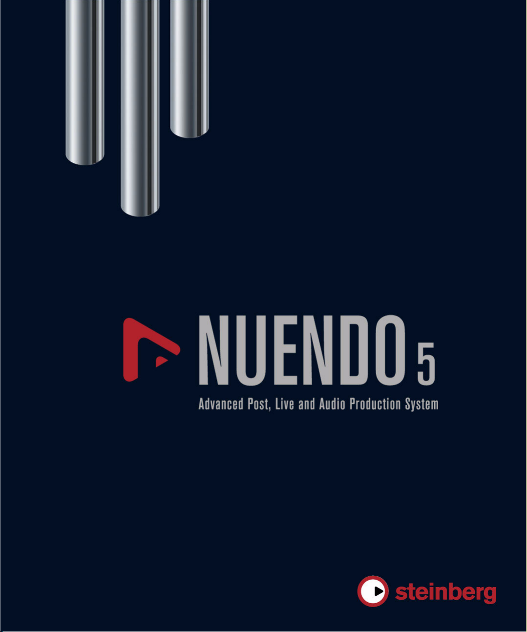
ModMachine combines delay modulation and filter frequency/resonance modulation and can provide many
interesting modulation effects. It also features a Drive
parameter for distortion effects.
The following parameters are available:
Parameter Description
Delay This is where you specify the base note value for the de-
Delay –
Sync button
Rate The Rate parameter sets the base note value for tempo
Rate –
Sync button
The included effect plug-ins
6
lay if tempo sync is on (1/1–1/32, straight, triplet, or dotted). If tempo sync is off, the delay time can be set freely
in milliseconds.
The button below the Delay knob is used to switch
tempo sync for the Delay parameter on or off.
syncing the delay modulation (1/1 to 1/32, straight, triplet,
or dotted). If tempo sync is off, the rate can be set freely.
The button below the Rate knob is used to switch tempo
sync for the Rate parameter on or off.
Page 7
Parameter Description
Width Sets the amount of delay pitch modulation. Note that al-
Feedback Sets the number of repeats for the delay.
Drive Adds distortion to the feedback loop. The longer the
Mix Sets the level balance between the dry signal and the ef-
Nudge button Clicking the Nudge button once will momentarily speed
Signal path
graphic and
Filter position
Filter type (in
graphic display)
Freq Sets the cutoff frequency for the filter. It is only available
Speed Sets the speed of the filter frequency LFO modulation.
Speed –
Sync button
Range Lo/Hi These knobs specify the range (in Hz) of the filter fre-
Spatial Introduces an offset between the channels to create a
Q-Factor Controls the resonance of the filter. It is only available if
Speed Sets the speed of the filter resonance LFO modulation.
Speed –
Sync button
though the modulation affects the delay time, the sound
is mostly perceived as a vibrato or chorus-like effect.
Feedback, the more the delay repeats become distorted
over time.
fect. If ModMachine is used as a send effect, set this to
the maximum value (100
effect balance with the send.
up the audio coming into the plug-in, simulating an ana
log tape nudge type sound effect.
The filter can either be placed in the feedback loop of the
delay or in the output path of the effect (after the Drive
and Feedback parameters).
To switch between the “loop” and “output” positions, click
on the Filter section displayed in the graphic or click on
the Position field at the bottom right of the graphic.
The Type button allows you to select a filter type. A lowpass, band-pass, and high-pass filter are available.
if tempo sync for the Speed parameter (see below) is
deactivated and the parameter is set to “0”.
When using tempo sync, the Speed parameter sets the
base note value for tempo syncing the modulation (1/1
to 1/32, straight, triplet, or dotted). If tempo sync is off,
the speed can be set freely.
The button below the Speed knob is used to switch
tempo sync for the Speed parameter on or off.
quency modulation. Both positive (e. g. Lo set to 50 and
Hi set to 10000) and negative (e.
Hi set to 500) ranges can be set. If tempo sync is off and
the Speed is set to zero, these parameters are inactive
and the filter frequency is controlled by the Freq parame
ter instead.
stereo panorama effect for the filter frequency modula
tion. Turn clockwise for a more pronounced stereo effect.
filter resonance LFO tempo sync is deactivated and the
Speed parameter (see below) is set to “0”. When using
tempo sync, the resonance is controlled by the Speed
and Range parameters.
When using tempo sync, the Speed parameter sets the
base note value for tempo syncing the modulation (1/1
to 1/32, straight, triplet, or dotted). If tempo sync is off,
the speed can be set freely.
The button below the Speed knob is used to switch
tempo sync for the Speed parameter on or off.
%) as you can control the dry/
g. Lo set to 5000 and
-
Parameter Description
Range Lo/Hi These knobs specify the range of filter resonance mod-
Spatial Introduces an offset between the channels to create a
MonoDelay
-
ulation. Both positive (e. g. Lo set to 50 and Hi set to
100) and negative (e.
ranges can be set. If tempo sync is off and the Speed is
set to zero, these parameters are inactive and the filter
resonance is controlled by the Q-Factor parameter in
stead.
stereo panorama effect for the filter resonance modu
lation. Turn clockwise for a more pronounced stereo
effect.
g. Lo set to 100 and Hi set to 50)
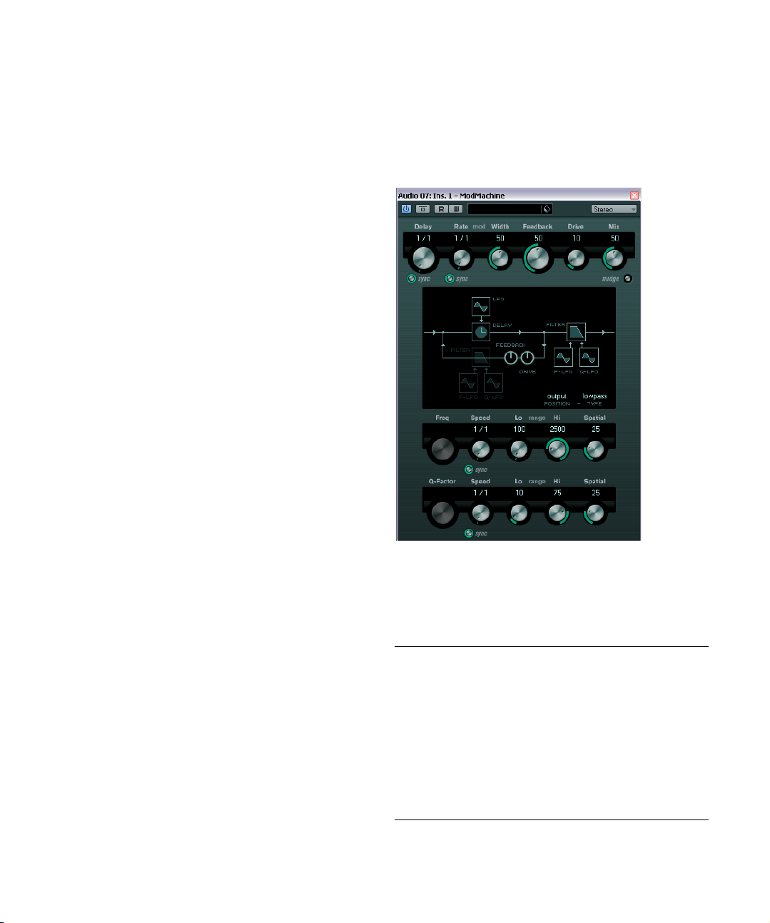
This is a mono delay effect that can either be tempobased or use freely specified delay time settings.
The following parameters are available:
Parameter Description
Delay This is where you specify the base note value for the delay
Sync button The button below the Delay knob is used to switch tempo
Feedback Sets the number of repeats for the delay.
Filter Lo This filter affects the feedback loop of the effect signal
Filter Hi This filter affects the feedback loop of the effect signal
Mix Sets the level balance between the dry signal and the ef-
if tempo sync is on (1/1–1/32, straight, triplet, or dotted).
If tempo sync is off, it sets the delay time in milliseconds.
sync on or off.
and allows you to roll off low frequencies from 10
Hz. The button below the knob activates/deactivates
800
the filter.
and allows you to roll off high frequencies from 20
down to 1.2
deactivates the filter.
fect. If MonoDelay is used as a send effect, set this to the
maximum value as you can control the dry/effect balance
with the send.
kHz. The button below the knob activates/
-
-
Hz up to
kHz
The included effect plug-ins
7
Page 8
The delay can also be controlled from another signal
source via the side-chain input. When the side-chain signal exceeds the threshold, the delay repeats are silenced.
When the signal drops below the threshold, the delay repeats reappear. For a description of how to set up sidechain routing, see the chapter “Audio effects” in the Oper
ation Manual.
The delay can also be controlled from another signal
source via the side-chain input. When the side-chain signal exceeds the threshold, the delay repeats are silenced.
When the signal drops below the threshold, the delay repeats reappear. For a description of how to set up side-
-
chain routing, see the chapter “Audio effects” in the Oper
ation Manual.
-
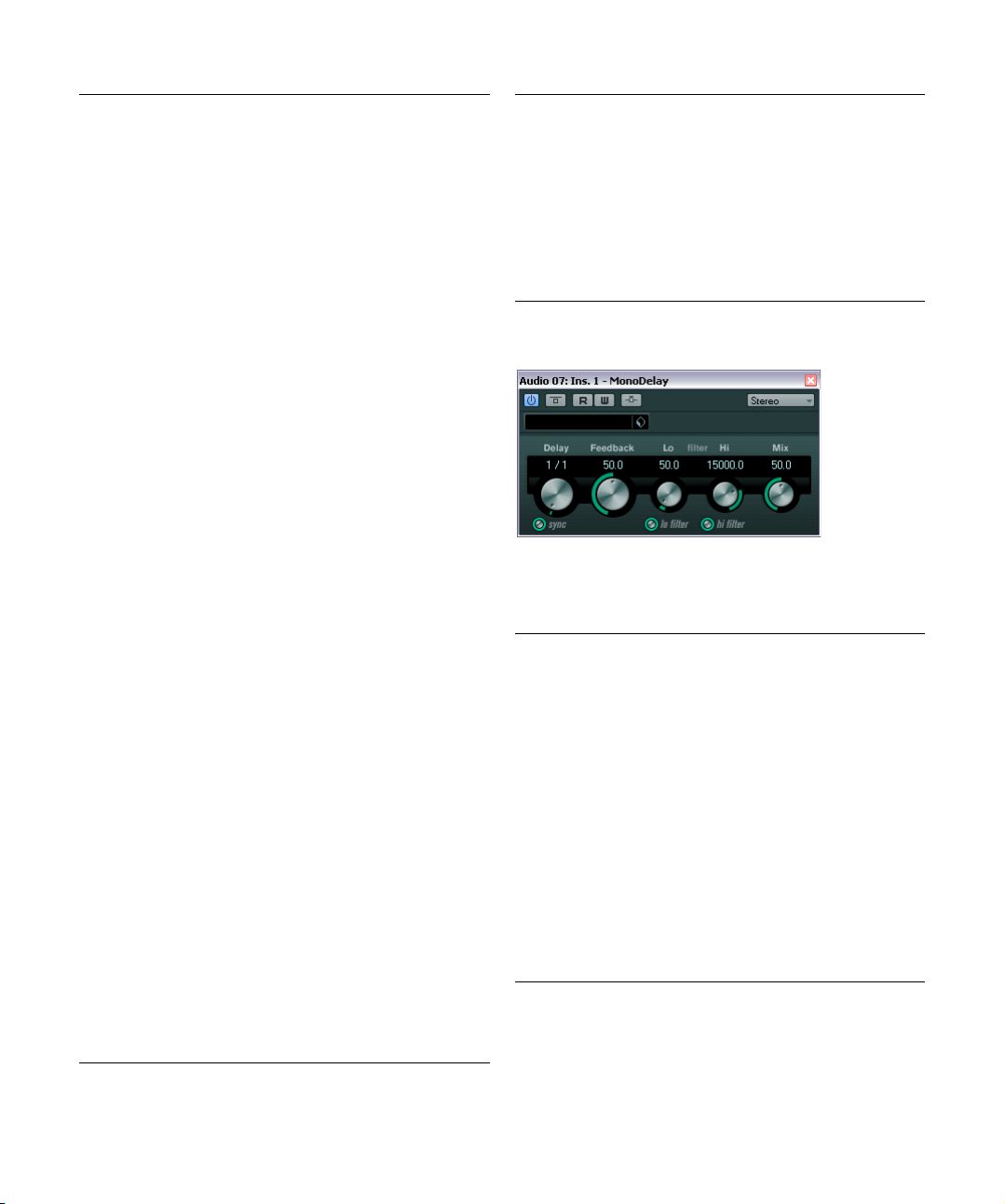
PingPongDelay
This is a stereo delay effect that alternates each delay repeat between the left and right channels. The effect can
either be tempo-based or use freely specified delay time
settings.
The following parameters are available:
Parameter Description
Delay This is where you specify the base note value for the delay
Sync button The button below the Delay Time knob is used to switch
Feedback Sets the number of repeats for the delay.
Filter Lo This filter affects the feedback loop and allows you to roll
Filter Hi This filter affects the feedback loop and allows you to roll
Spatial Sets the stereo width for the left/right repeats. Turn clock-
Mix Sets the level balance between the dry signal and the ef-
if tempo sync is on (1/1–1/32, straight, triplet, or dotted).
If tempo sync is off, it sets the delay time in milliseconds.
tempo sync on or off.
off low frequencies up to 800
knob activates/deactivates the filter.
off high frequencies from 20
button below the knob activates/deactivates the filter.
wise for a more pronounced stereo “ping-pong” effect.
fect. If PingPongDelay is used as a send effect, set this to
the maximum value as you can control the dry/effect bal
ance with the send.
Hz. The button below the
kHz down to 1.2 kHz. The
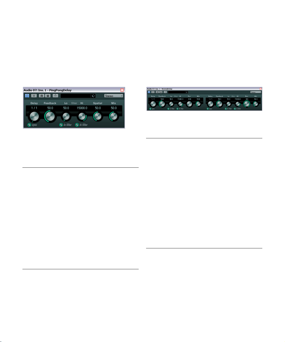
StereoDelay
StereoDelay has two independent delay lines which either
use tempo-based or freely specified delay time settings.
The following parameters are available:
Parameter Description
Delay 1 & 2 Using these controls you specify the base note value for
Sync button The buttons below the Delay knobs are used to turn
Feedback
1 & 2
Filter Lo
1 & 2
Filter Hi
1 & 2
Pan 1 & 2 These controls are used to set the stereo position for
Mix 1 & 2 Use these controls to set the level balance between the
The delay can also be controlled from another signal
-
source via the side-chain input. When the side-chain signal exceeds the threshold, the delay repeats are silenced.
When the signal drops below the threshold, the delay re
peats reappear. For a description of how to set up sidechain routing, see the chapter “Audio effects” in the Operation Manual.
the delay if tempo sync is on (1/1–1/32, straight, triplet,
or dotted). If tempo sync is off, they set the delay time in
milliseconds.
tempo sync on or off for the respective delay.
The Feedback controls set the number of repeats for
each delay.
These filters affect the feedback loop and allow you to roll
off low frequencies up to 800
knobs activate/deactivate the filter.
These filters affect the feedback loop and allow you to roll
off high frequencies from 20
buttons below the knobs activate/deactivate the filter.
each delay.
dry signal and the effect. If StereoDelay is used as a send
effect, set them to the maximum value (100
control the dry/effect balance with the send.
Hz. The buttons below the
kHz down to 1.2 kHz. The
%) as you can
-
The included effect plug-ins
8
Page 9
Distortion plug-ins
This section contains descriptions of the plug-ins in the
“Distortion” category.
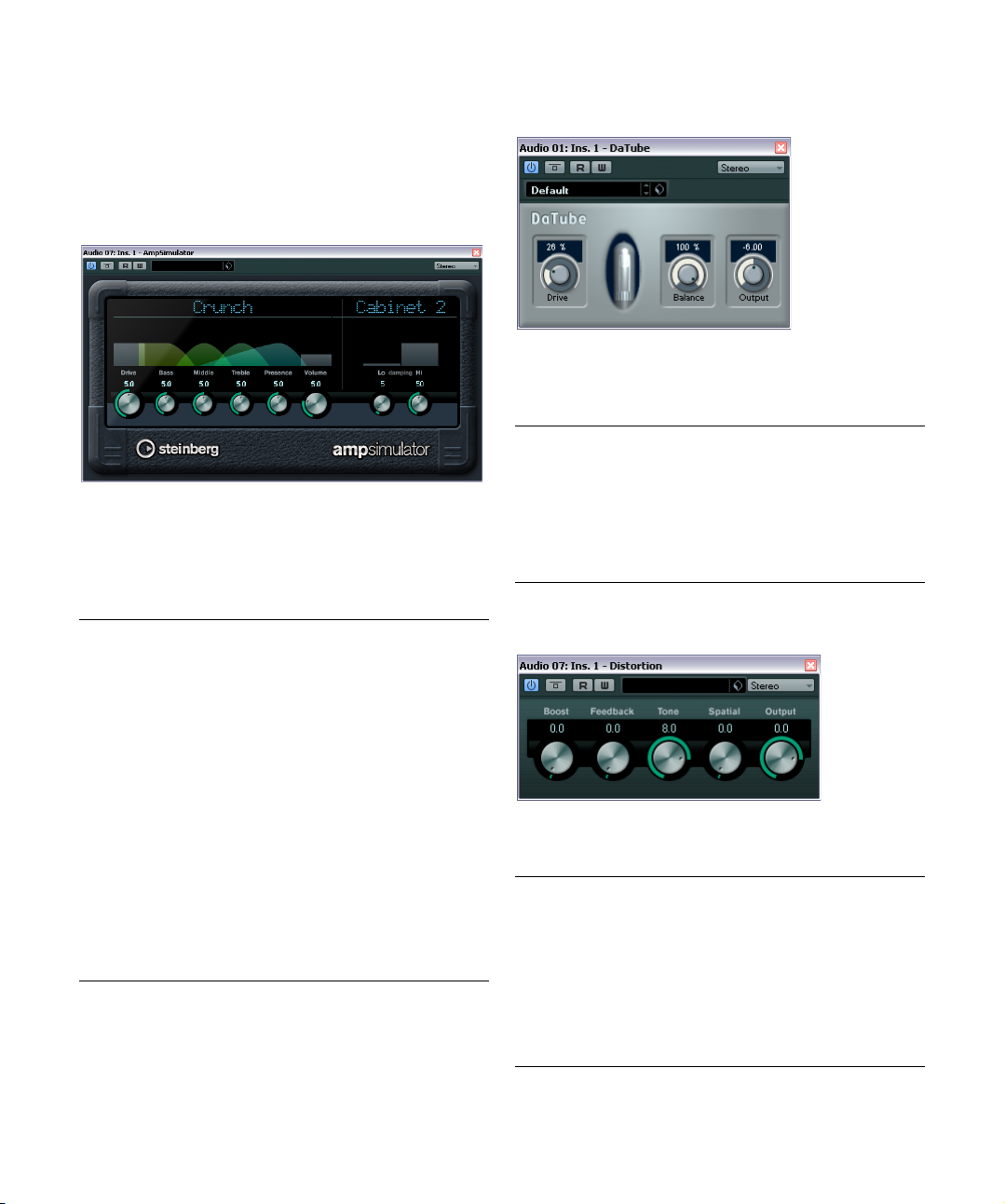
AmpSimulator
AmpSimulator is a distortion effect, emulating the sound
of various types of guitar amp and speaker cabinet combinations. A wide selection of amp and cabinet models is
available.
The following parameters are available:
Parameter Description
Amplifier
pop-up menu
Drive Controls the amount of amp overdrive.
Bass Tone control for the low frequencies.
Middle Tone control for the mid frequencies.
Treble Tone control for the high frequencies.
Presence Boosts or dampens the higher frequencies.
Volume Controls the overall output level.
Cabinet
pop-up menu
Damping Lo/Hi Further tone controls for shaping the sound of the selected
This pop-up menu is opened by clicking on the amplifier
name shown at the top of the amp section. It allows you
to select an amplifier model. The amp section can be by
passed by selecting “No Amp”.
This pop-up menu is opened by clicking on the cabinet
name shown at the top of the cabinet section. It allows
you to select a speaker cabinet model. This section can
be bypassed by selecting “No Speaker”.
speaker cabinet. Click on the values, enter a new value and
press the [Enter] key.
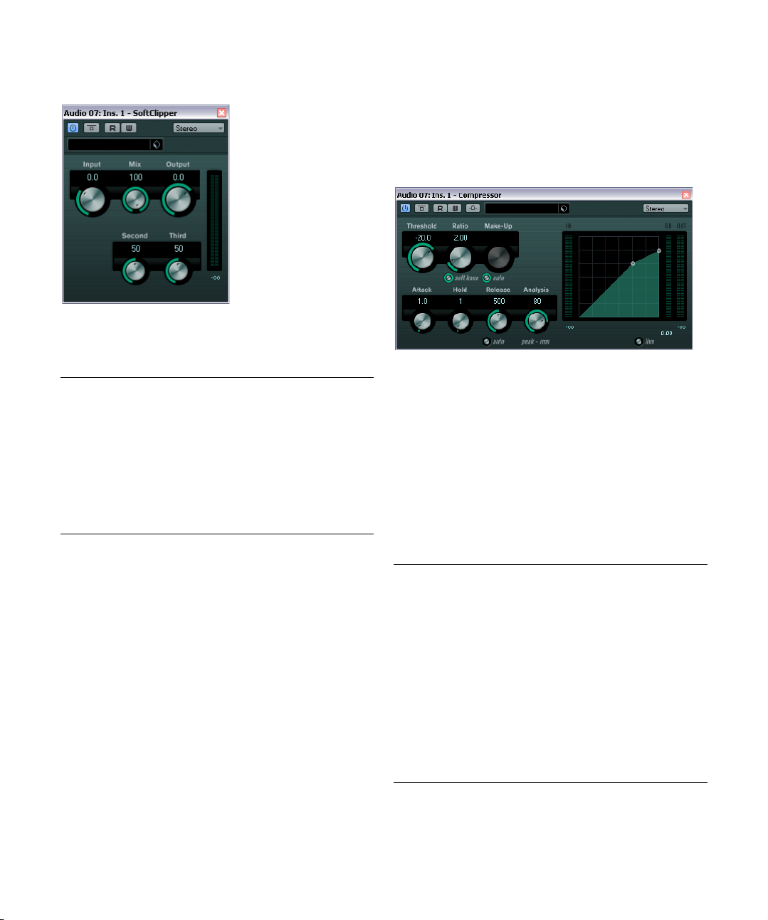
DaTube
This effect emulates the characteristic warm, lush sound
of a tube amplifier.
The following parameters are available:
Parameter Description
Drive Regulates the pre-gain of the “amplifier”. Use high values
Balance Controls the balance between the signal processed by the
Output Adjusts the post-gain, or output level, of the “amplifier”.
if you want an overdriven sound just on the verge of
distortion.
Drive parameter and the dry input signal. For maximum
drive effect, set this to its highest value.
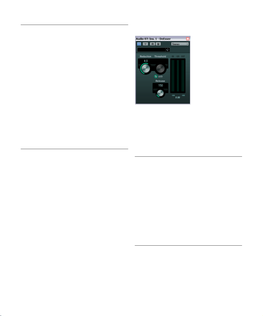
Distortion
-
Distortion will add crunch to your tracks.
The following parameters are available:
Parameter Description
Boost Increases the distortion amount.
Feedback Feeds part of the output signal back to the effect input,
Tone Lets you select a frequency range to which to apply the
Spatial Changes the distortion characteristics of the left and right
Output Raises or lowers the signal going out of the effect.
increasing the distortion effect.
distortion effect.
channel, thus creating a stereo effect.
The included effect plug-ins
9
Page 10
SoftClipper
This effect adds soft overdrive, with independent control
over the second and third harmonic.
The following parameters are available:
Parameter Description
Input Regulates the pre-gain. Use high values if you want an
Mix Setting Mix to 0 means that no processed signal is added
Output Adjusts the post-gain, or output level.
Second Allows you to adjust the amount of the second harmonic
Third Allows you to adjust the amount of the third harmonic in
overdriven sound just on the verge of distortion.
to the original signal.
in the processed signal.
the processed signal.
Dynamics plug-ins
This section contains descriptions of the plug-ins in the
“Dynamics” category.
Compressor
Compressor reduces the dynamic range of the audio, making softer sounds louder or louder sounds softer, or both.
Compressor features separate controls for threshold, ratio,
attack, hold, release and make-up gain parameters. Com
pressor features a separate display that graphically illustrates the compressor curve shaped according to the
Threshold and Ratio parameter settings. Compressor also
features a Gain Reduction meter that shows the amount of
gain reduction in dB, Soft knee/Hard knee compression
modes and a program-dependent Auto feature for the Re
lease parameter.
The following parameters are available:
Parameter Description
Threshold
(-60 to 0 dB)
Ratio
(1:1 to 8:1)
Soft Knee
button
Make-up
(0 to 24 dB or
Auto mode)
Determines the level where Compressor “kicks in”. Signal
levels above the set threshold are affected, but signal lev
els below are not processed.
Sets the amount of gain reduction applied to signals over
the set threshold. A ratio of 3:1 means that for every 3
the input level increases, the output level will increase by
only 1
dB.
If this button is off, signals above the threshold are compressed instantly according to the set ratio (hard knee).
When Soft Knee is activated, the onset of compression is
more gradual, producing a less drastic result.
This parameter is used to compensate for output gain loss,
caused by compression. If the Auto button is activated, the
knob becomes dark and the output is automatically ad
justed for gain loss.
dB
-
-
-
-
The included effect plug-ins
10
Page 11
Parameter Description
Attack
(0.1 to
ms)
100
Hold
(0 to
ms)
5000
Release
(10 to
1000
ms or
Auto mode)
Analysis
(0 to 100)
(Pure Peak to
Pure RMS)
Live button When this button is activated, the “look ahead” feature of
Determines how fast Compressor will respond to signals
above the set threshold. If the attack time is long, more of
the early part of the signal (attack) passes through unproc
essed.
Sets the time the applied compression will affect the signal
after exceeding the threshold.
Short hold times are useful for “DJ-style” ducking, while
longer hold times are required for music ducking, e.
when working on a documentary film.
Sets the amount of time it takes for the gain to return to its
original level when the signal drops below the threshold
level. If the Auto button is activated, Compressor will auto
matically find an optimal release setting that varies depending on the audio material.
Determines whether the input signal is analyzed according
to peak or RMS values (or a mixture of both). A value of 0 is
pure peak and 100 pure RMS. RMS mode operates using
the average power of the audio signal as a basis, whereas
Peak mode operates more on peak levels. As a general
guideline, RMS mode works better on material with few
transients such as vocals, and Peak mode better for per
cussive material, with a lot of transient peaks.
Compressor is disengaged. Look ahead produces more
accurate processing, but adds a certain amount of latency
as a trade-off. When Live mode is activated, there is no la
tency, which might be better for “live” processing.
g.
The compression can also be controlled from another
signal source via the side-chain input. When the side-chain
signal exceeds the threshold, the compression is triggered.
For a description of how to set up side-chain routing, see
the chapter “Audio effects” in the Operation Manual.
DeEsser
-
-
A de-esser is used to reduce excessive sibilance, primarily
for vocal recordings. Basically, it is a special type of com-
-
pressor that is tuned to be sensitive to the frequencies produced by the “s” sound, hence the name de-esser. Close
proximity microphone placement and equalizing can lead to
situations where the overall sound is just right, but there is a
-
problem with sibilants.
The following parameters are available:
Parameter Description
Reduction Controls the intensity of the de-essing effect.
Threshold When the Auto Threshold option is deactivated, you can
Auto The Auto Threshold function automatically and continu-
Release Sets the amount of time it takes for the de-essing effect
Level meters Indicate the dB values of the input (IN) and output (OUT)
use this control to set a threshold for the incoming signal
level, above which the plug-in starts to reduce the sibilants.
ally chooses an optimum threshold setting independent
of the input signal.
The Auto Threshold function does not work for low-level
signals (< -30
such a file, set the threshold manually.
to return to zero when the signal drops below the tresh
old value.
signals as well as the value by which the level of the sibi
lant (or s-frequency) is reduced (GR). The gain reduction
meter shows values between 0
dB (the s-frequency level is lowered by 20 dB).
-20
db peak level). To reduce the sibilants in
dB (no reduction) and
-
-
The included effect plug-ins
11
Page 12
Positioning the DeEsser in the signal chain
When recording a voice, the de-esser’s position in the
signal chain is usually located after the microphone preamp and before a compressor/limiter. This keeps the
compressor/limiter from unnecessarily limiting the overall
signal dynamics.
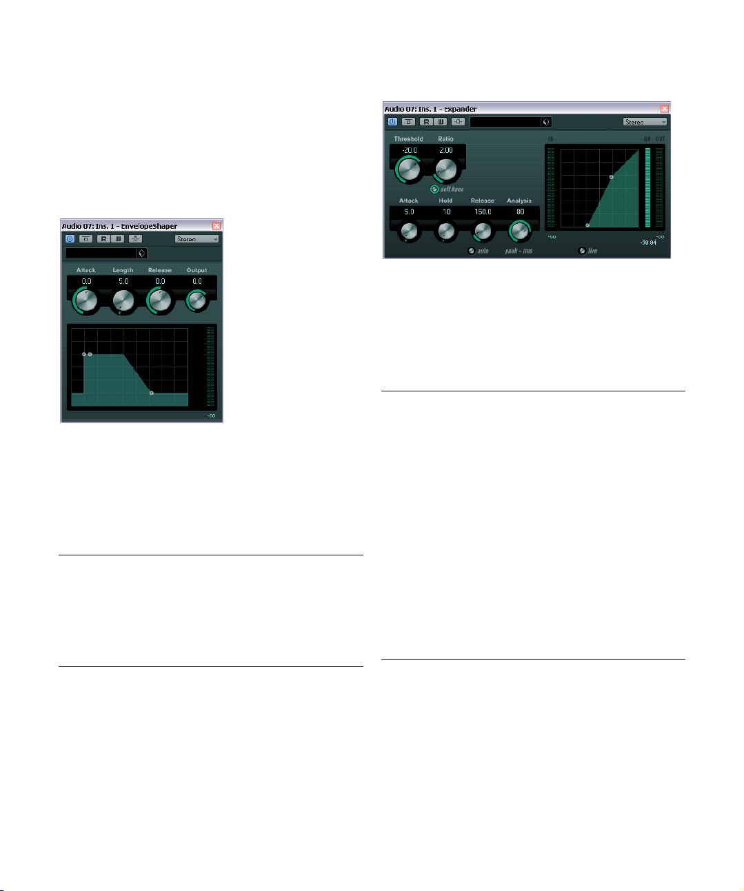
EnvelopeShaper
EnvelopeShaper can be used to cut or boost the gain of
the Attack and Release phase of audio material. You can
either use the knobs or drag the breakpoints in the graph
ical display to change parameter values. Be careful with
levels when boosting the gain and if needed reduce the
Output level to avoid clipping.
The following parameters are available:
Parameter Description
Attack (-20 to 20 dB) Changes the gain of the Attack phase of the sig-
Length (5 to 200 ms) Determines the length of the Attack phase.
Release (-20 to 20 dB) Changes the gain of the Release phase of the
Output (-24 to 12 dB) Sets the output level.
nal.
signal.
Expander
Expander reduces the output level in relation to the input
level for signals below the set threshold. This is useful
when you want to enhance the dynamic range or reduce
the noise in quiet passages. You can either use the knobs
or drag the breakpoints in the graphical display to change
the Threshold and the Ratio parameter values.
The following parameters are available:
Parameter Description
-
Threshold
(-60 to 0 dB)
Ratio
(1:1 to 8:1)
Soft Knee
button
Attack (0.1 to
100
ms)
Hold (0 to
ms)
2000
Release
(10 to
ms or
1000
Auto mode)
Determines the level where expansion “kicks in”. Signal
levels below the set threshold are affected, but signal lev
els above are not processed.
Determines the amount of gain boost applied to signals
below the set threshold.
If this button is off, signals below the threshold are expanded instantly according to the set ratio (“hard knee”).
When Soft Knee is activated, the onset of expansion is
more gradual, producing a less drastic result.
Determines how fast Expander responds to signals below
the set threshold. If the attack time is long, more of the early
part of the signal (attack) passes through unprocessed.
Sets the time the applied expansion will affect the signal
below the Threshold.
Sets the amount of time it takes for the gain to return to its
original level when the signal exceeds the threshold level. If
the Auto button is activated, Expander will automatically
find an optimal release setting that varies depending on
the audio material.
-
The included effect plug-ins
12
Page 13
Parameter Description
Analysis
(0 to 100)
(Pure Peak to
Pure RMS)
Live button When this button is activated, the “look ahead” feature of
Determines whether the input signal is analyzed according
to peak or RMS values (or a mixture of both). A value of 0 is
pure peak and 100 pure RMS. RMS mode operates using
the average power of the audio signal as a basis, whereas
Peak mode operates more on peak levels. As a general
guideline, RMS mode works better on material with few
transients such as vocals, and Peak mode better for per
cussive material, with a lot of transient peaks.
Expander is disengaged. Look ahead produces more ac
curate processing, but adds a certain amount of latency as
a trade-off. When Live mode is activated, there is no la
tency, which might be better for “live” processing.
-
The expansion can also be controlled from another signal source via the side-chain input. When the side-chain
signal exceeds the threshold, the expansion is triggered.
For a description of how to set up side-chain routing, see
the chapter “Audio effects” in the Operation Manual.
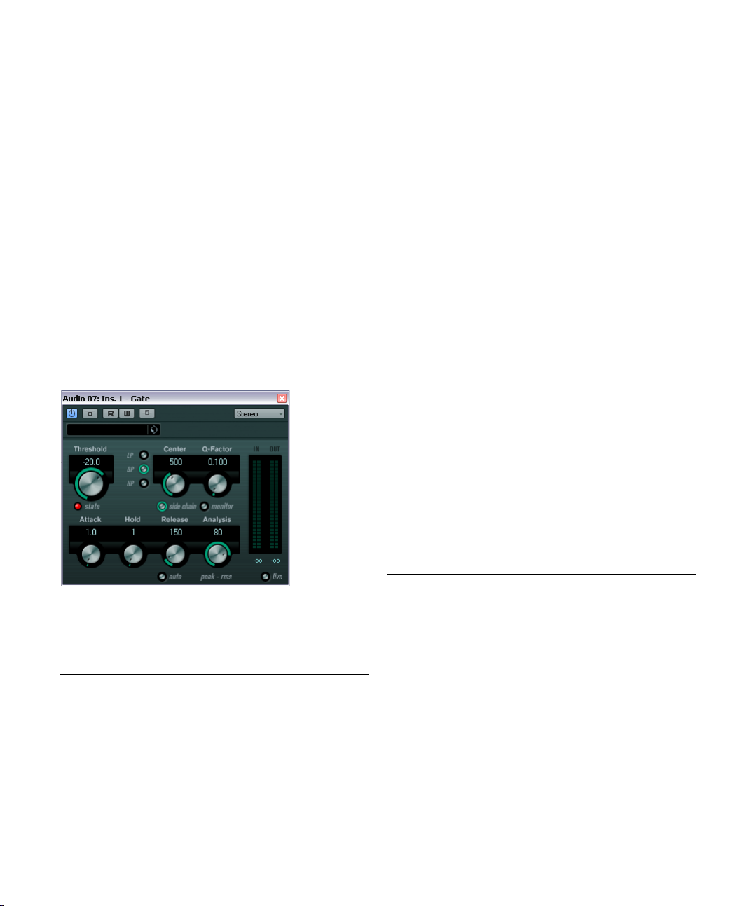
Gate
Parameter Description
Filter buttons
(LP, BP, and
HP)
Side-Chain
button
-
Center (50 Hz
to 20000
Q-Factor (0.01
to 10000)
Monitor button Allows you to monitor the filtered signal.
Attack (0.1 to
ms)
1000
Hold
(0 to 2000 ms)
Release
(10 to 1000 ms
or Auto mode)
Analysis
(0 to 100)
(Pure Peak to
Pure RMS)
Live button When this button is activated, the “look ahead” feature of
When the Side-Chain button (see below) is activated,
you can use these buttons to set the filter type to either
low-pass, band-pass, or high-pass.
This button (below the Center knob) activates the sidechain filter. The input signal can then be shaped accord
ing to set filter parameters. Internal side-chaining can be
useful for tailoring how the Gate operates.
When the Side-Chain button is activated, this sets the
Hz)
center frequency of the filter.
When the Side-Chain button is activated, this sets the
resonance of the filter.
Sets the time it takes for the gate to open after being triggered. If the Live button (see below) is deactivated, it ensures that the gate will already be open when a signal
above the threshold level is played back. Gate manages
this by “looking ahead” in the audio material, checking for
signals loud enough to pass the gate.
Determines how long the gate stays open after the signal
drops below the threshold level.
Sets the amount of time it takes for the gate to close (after the set hold time). If the Auto button is activated, Gate
will find an optimal release setting, depending on the au
dio material.
Determines whether the input signal is analyzed according
to Peak or RMS values (or a mixture of both). A value of 0 is
pure Peak and 100 pure RMS. RMS mode operates using
the average power of the audio signal as a basis, whereas
Peak mode operates more on peak levels. As a general
guideline, RMS mode works better on material with few
transients such as vocals, and Peak mode better for per
cussive material, with a lot of transient peaks.
Gate is disengaged. Look ahead produces more accurate
processing, but adds a certain amount of latency as a
trade-off. When Live mode is activated, there is no la
tency, which might be better for “live” processing.
-
-
-
-
Gating, or noise gating, silences audio signals below a set
threshold level. As soon as the signal level exceeds the set
threshold, the gate opens to let the signal through.
The following parameters are available:
Parameter Description
Threshold
(-60 to 0 dB)
State LED Indicates whether the gate is open (LED lights up in
Determines the level where Gate is activated. Signal levels above the set threshold trigger the gate to open, and
signal levels below the set threshold will close the gate.
green), closed (LED lights up in red) or something in be
tween (LED lights up in yellow).
The included effect plug-ins
The gate can also be controlled from another signal
source via the side-chain input. When the side-chain sig
nal exceeds the threshold, the gate opens. For a description of how to set up side-chain routing, see the chapter
“Audio effects” in the Operation Manual.
-
13
-
Page 14
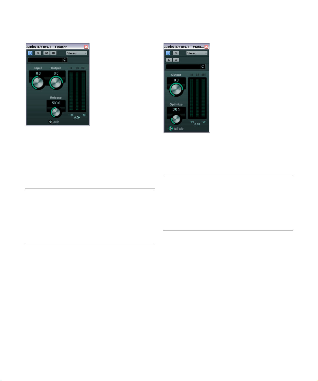
Limiter
Limiter is designed to ensure that the output level never
exceeds a set output level, to avoid clipping in following
devices. Limiter can adjust and optimize the Release parameter automatically according to the audio material, or it
can be set manually. Limiter also features separate meters
for the input, output and the amount of limiting (middle
meters).
The following parameters are available:
Parameter Description
Input
(-24 to +24 dB)
Output
(-24 to +6 dB)
Release
(0.1 to 1000 ms
or Auto mode)
Allows you to adjust the input gain.
Determines the maximum output level.
Sets the amount of time it takes for the gain to return to
its original level. If the Auto button is activated, Limiter
will automatically find an optimal release setting that var
ies depending on the audio material.
Maximizer
Maximizer is used to raise the loudness of audio material
without the risk of clipping. Optionally, there is a soft clip
function that removes short peaks in the input signal and
introduces a warm tube-like distortion to the signal.
The following parameters are available:
Parameter Description
Output
(-24 to +6 dB)
Optimize
(0 to 100)
Soft Clip
button
-
Determines the maximum output level. Should normally be
set to 0 (to avoid clipping).
Determines the loudness of the signal.
When this button is activated, Maximizer starts limiting (or
clipping) the signal “softly”, at the same time generating
harmonics which add a warm, tube-like characteristic to
the audio material.
The included effect plug-ins
14
Page 15
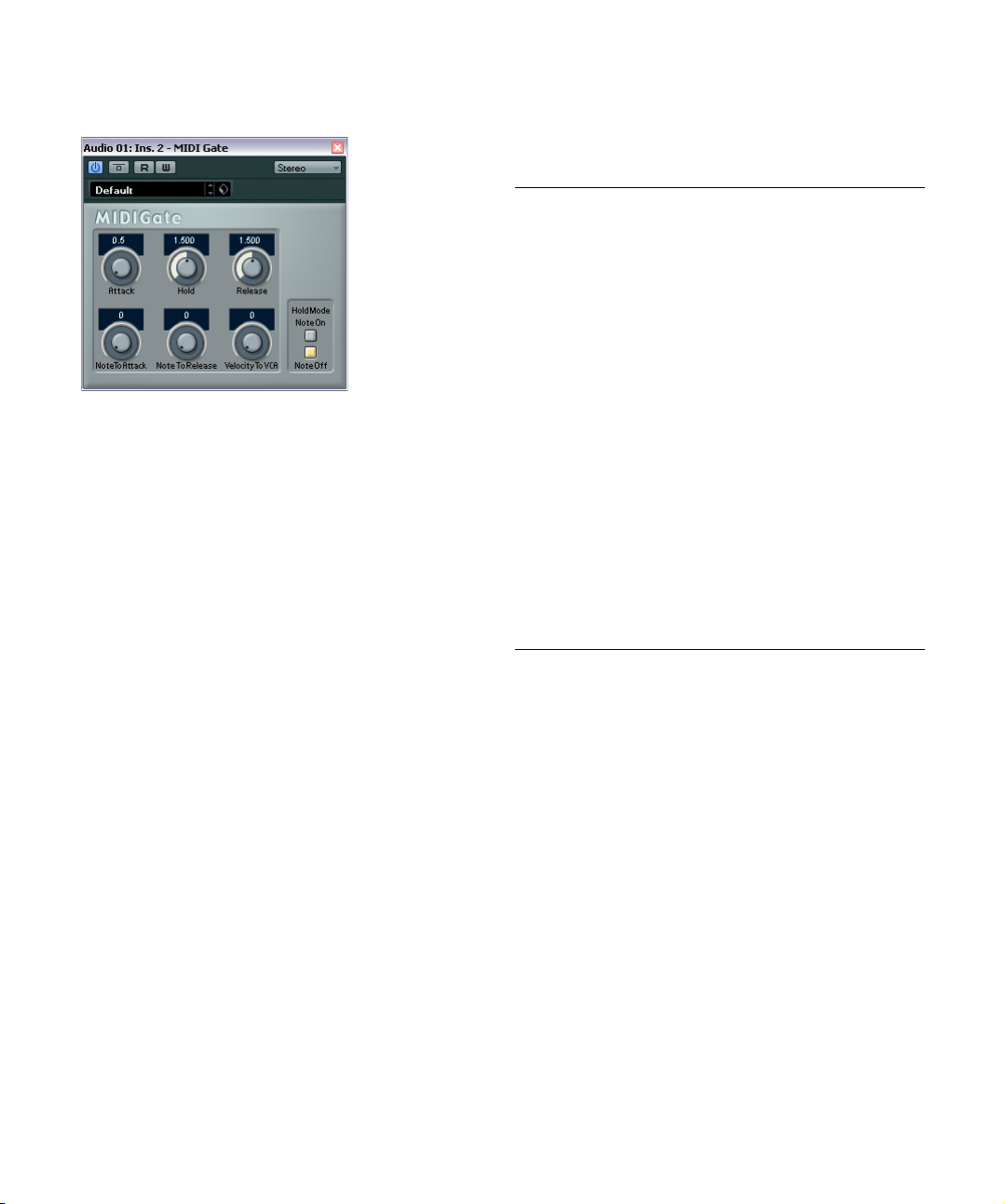
MIDI Gate
Gating, in its fundamental form, silences audio signals below a set threshold level. When a signal rises above the
set level, the gate opens to let the signal through while
signals below the set level are cut off. MIDI Gate, however, is not triggered by threshold levels, but MIDI notes.
Hence it needs both audio and MIDI data to function.
Setting up
To set up MIDI Gate, proceed as follows:
1. Select the audio to be affected by MIDI Gate.
This can be audio material from any audio track, or even a live audio input
(provided you have a low latency audio card).
2. Select MIDI Gate as an insert effect for the audio
track.
The MIDI Gate control panel opens.
3. Select a MIDI track to control the MIDI Gate effect.
This can be an empty MIDI track or a MIDI track containing data, it does not
matter. However, if you wish to use MIDI Gate in realtime – as opposed to
using a recorded part – the track has to be selected for the effect to re
ceive the MIDI output.
4. Open the Output Routing pop-up menu for the MIDI
track and select the MIDI Gate option.
The MIDI output from the track is now routed to the MIDI Gate effect.
What to do next depends on whether you are using live or
recorded audio and whether you are using realtime or re
corded MIDI. We will assume for the purposes of this
manual that you are using recorded audio, and play the
MIDI in realtime.
5. Make sure the MIDI track is selected, and start playback.
-
-
6. Play a few notes on your MIDI keyboard.
As you can hear, the audio track material is affected by what you play on
your MIDI keyboard.
The following MIDI Gate parameters are available:
Parameter Description
Attack Determines how long it takes for the gate to open after
Hold Regulates how long the gate remains open after a note-
Release Determines how long it takes for the gate to close (in ad-
Note To Attack Determines to which extent the velocity values of the MIDI
Note To
Release
Velocity To
VCA
Hold Mode Use this switch to set the Hold Mode. In Note-On mode,
receiving a signal that triggers it.
on or note-off message (see Hold Mode below).
dition to the value set with the Hold parameter).
notes affect the attack. The higher the value, the more the
attack time increases with high note velocities. Negative
values give shorter attack times with high velocities. If you
do not wish to use this parameter, set it to the 0 position.
Determines to which extent the velocity values of the MIDI
notes affect the release. The higher the value, the more
the release time increases. If you do not wish to use this
parameter, set it to the 0 position.
Controls to which extent the velocity values of the MIDI
notes determine the output volume. At a value of 127 the
volume is controlled entirely by the velocity values, and at
a value of 0 the velocities have no effect on the volume.
the gate only remains open for the time set with the Hold
and Release parameters, regardless of the length of the
MIDI note that triggered the gate. In Note-Off mode, the
gate remains open for as long as the MIDI note plays, and
then the Hold and Release parameters are applied.
The included effect plug-ins
15
Page 16
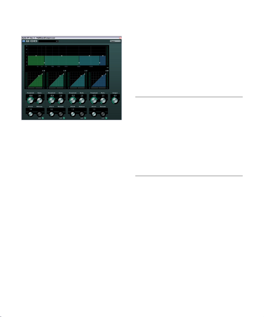
MultibandCompressor
The MultibandCompressor allows a signal to be split into
a maximum of four frequency bands, each with its own
freely adjustable compressor characteristic. The signal is
processed on the basis of the settings that you have made
in the Frequency Band and Compressor sections. You
can specify the level, bandwidth and compressor charac
teristics for each band by using the various controls.
The Frequency Band editor
The Frequency Band editor in the upper half of the panel is
where you set the width of the frequency bands as well as
their level after compression. Two value scales and a num
ber of handles are available. The vertical value scale to the
left shows the input gain level of each frequency band.
The horizontal scale shows the available frequency range.
The handles provided in the Frequency Band editor can
be dragged with the mouse. You use them to set the cor
ner frequency range and the input gain levels for each frequency bands.
• The handles at the sides are used to define the frequency
range of the different frequency bands.
• By using the handles on top of each frequency band, you can
cut or boost the input gain by +/- 15 dB after compression.
Soloing frequency bands
A frequency band can be soloed using the S button in
each compressor section. Only one band can be soloed
at a time.
Using the Compressor section
By moving breakpoints or using the corresponding knobs,
you can specify the Threshold and Ratio. The first breakpoint from which the line deviates from the straight diagonal will be the threshold point.
For each of the four bands the following compressor parameters are available:
Parameter Description
-
Threshold
(-60 to 0 dB)
Ratio
(1000 to 8000)
(1:1 to 8:1)
Attack
(0.1 to 100 ms)
Release
(10 to 1000 ms
or Auto mode)
Determines the level where Compressor “kicks in”. Signal levels above the set threshold are affected, but signal
levels below are not processed.
Determines the amount of gain reduction applied to signals over the set threshold. A ratio of 3000 (3:1) means
that for every 3
level increases by only 1
Determines how fast the compressor responds to signals above the set threshold. If the attack time is long,
more of the early part of the signal (attack) will pass
through unprocessed.
Sets the amount of time it takes for the gain to return to
its original level when the signal drops below the thresh
old level. If the Auto button is activated, the compressor
will automatically find an optimal release setting that var
ies depending on the audio material.
dB the input level increases, the output
dB.
The Output control
The Output knob controls the total output level that the
MultibandCompressor passes on to Nuendo. The range is
from -24 to +24
dB.
-
-
-
Bypassing frequency bands
Each frequency band can be bypassed using the B button
in each compressor section.
The included effect plug-ins
16
Page 17
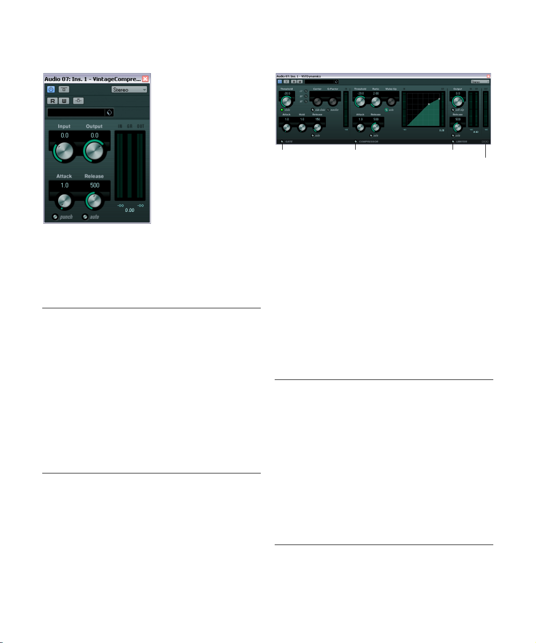
VintageCompressor
Limiter
Module Configuration
Gate Compressor
This is modelled after vintage type compressors. This compressor features separate controls for input and output
gain, attack, and release. In addition, there is a Punch mode
which preserves the attack phase of the signal and a program-dependent Auto feature for the Release parameter.
The available parameters work as follows:
Parameter Description
Input
(-24 to 48 dB)
Output
(-48 to 24 dB)
Attack
(0.1 to 100 ms)
Punch
(On/Off)
Release
(10 to 1000 ms
or Auto mode)
The compression can also be controlled from another
signal source via the side-chain input. When the side-chain
signal exceeds the threshold, the compression is triggered.
For a description of how to set up side-chain routing, see
the chapter “Audio effects” in the Operation Manual.
In combination with the Output setting, this parameter
determines the compression amount. The higher the in
put gain setting and the lower the output gain setting, the
more compression is applied.
Sets the output gain.
Determines how fast the compressor responds. If the attack time is long, more of the early part of the signal (attack) passes through unprocessed.
When this is activated, the early attack phase of the signal is preserved, retaining the original “punch” in the audio material, even with short Attack settings.
Sets the amount of time it takes for the gain to return to
its original level. If the Auto button is activated, Vintage
Compressor will automatically find an optimal release set
ting that varies depending on the audio material.
VSTDynamics
VSTDynamics is an advanced dynamics processor. It combines three separate processors: Gate, Compressor and
Limiter, covering a variety of dynamic processing functions.
The window is divided into three sections, containing con
trols and meters for each processor.
Activating the individual processors
You activate the individual processors using the buttons
at the bottom of the plug-in panel.
The Gate section
Gating, or noise gating, is a method of dynamic processing that silences audio signals below a set threshold level.
As soon as the signal level exceeds the set threshold, the
-
gate opens to let the signal through. The Gate trigger in
put can also be filtered using an internal side-chain.
The following parameters are available:
Parameter Description
Threshold
(-60 to 0 dB)
State LED Indicates whether the gate is open (LED lights up in
Side-Chain
button
LP (low-pass),
BP (band-pass),
HP (high-pass)
Center (50 to
Hz)
22000
Determines the level where Gate is activated. Signal levels above the set threshold trigger the gate to open, and
signal levels below the set threshold close the gate.
green), closed (LED lights up in red) or something in be
tween (LED lights up in yellow).
This button activates the internal side-chain filter. You can
use this to filter out parts of the signal that might other
wise trigger the gate in places you not want it to, or to
boost frequencies you wish to accentuate, allowing for
more control over the gate function.
These buttons set the basic filter mode.
Sets the center frequency of the filter.
-
-
-
-
The included effect plug-ins
17
Page 18

Parameter Description
Q-Factor
(0.001 to
10000)
Monitor
(On/Off)
Attack
(0.1 to 100 ms)
Hold
(0 to 2000 ms)
Release
(10 to 1000 ms
or Auto mode)
Sets the resonance or width of the filter.
Allows you to monitor the filtered signal.
Sets the time it takes for the gate to open after being
triggered.
Determines how long the gate stays open after the signal drops below the threshold level.
Sets the amount of time it takes for the gate to close (after
the set hold time). If the Auto button is activated, Gate will
find an optimal release setting, depending on the audio
material.
The Compressor section
The compressor reduces the dynamic range of the audio,
making softer sounds louder or louder sounds softer, or
both. It works like a standard compressor with separate
controls for threshold, ratio, attack, release and make-up
gain. The compressor features a separate display that
graphically illustrates the compressor curve shaped ac
cording to the Threshold, Ratio and Make-Up Gain parameter settings. It also features Gain Reduction meters
and a program-dependent Auto feature for the Release
parameter.
The available parameters work as follows:
Parameter Description
Threshold
(-60 to 0 dB)
Ratio
(1:1 to 8:1)
Make-Up
(0 to 24 dB)
Attack
(0.1 to 100 ms)
Determines the level where the compressor “kicks in”.
Signal levels above the set threshold are affected, but
signal levels below are not processed.
Determines the amount of gain reduction applied to signals above the set threshold. A ratio of 3:1 means that for
dB the input level increases, the output level in-
every 3
creases by only 1 dB.
This parameter is used to compensate for output gain
loss, caused by compression. When the Auto button is
activated, gain loss is being compensated automatically.
Determines how fast the compressor responds to signals
above the set threshold. If the attack time is long, more of
the early part of the signal (attack) passes through un
processed.
-
-
Parameter Description
Release
(10 to 1000 ms
or Auto mode)
Graphical
display
Sets the amount of time it takes for the gain to return to
its original level when the signal drops below the thresh
old level. If the Auto button is activated, the compressor
will automatically find an optimal release setting that var
ies depending on the audio material.
Use the graphical display to graphically set the Threshold
and Ratio values. To the left and right of the graphical dis
play you will find two meters that show the amount of gain
reduction in dB.
The Limiter section
The limiter is designed to ensure that the output level
never exceeds a set threshold, to avoid clipping in follow
ing devices. Conventional limiters usually require very accurate setting up of the attack and release parameters to
prevent the output level from going beyond the set thresh
old level. The limiter adjusts and optimizes these parameters automatically according to the audio material. You
can also adjust the Release parameter manually.
The following parameters are available:
Parameter Description
Output
(-24 to +6 dB)
Soft Clip
button
Release
(10 to 1000 ms
or Auto mode)
Determines the maximum output level. Signal levels
above the set threshold are affected, but signal levels be
low are left unaffected.
If this button is activated, the limiter acts differently. When
the signal level exceeds -6
clipping) the signal “softly”, at the same time generating
harmonics which add a warm, tube-like characteristic to
the audio material.
Sets the amount of time it takes for the gain to return to
its original level when the signal drops below the thresh
old level. If the Auto button is activated, the limiter will automatically find an optimal release setting that varies
depending on the audio material.
dB, Soft Clip starts limiting (or
The Module Configuration button
Using the Module Configuration button in the bottom right
corner of the plug-in panel, you can set the signal flow or
der for the three processors. Changing the order of the processors can produce different results, and the available
options allow you to quickly compare what works best for a
given situation. Simply click the Module Configuration but
ton to change to a different configuration. There are three
routing options:
• C-G-L (Compressor-Gate-Limit)
• G-C-L (Gate-Compressor-Limit)
• C-L-G (Compressor-Limit-Gate)
-
-
-
-
-
-
-
-
-
The included effect plug-ins
18
Page 19
EQ plug-ins
This section describes the plug-ins in the “EQ” category.
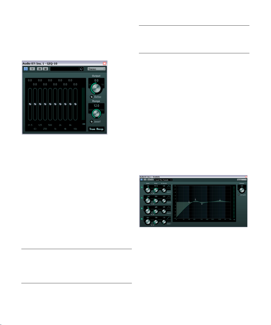
GEQ-10/GEQ-30
These graphic equalizers are identical in every respect except for the number of available frequency bands (10 and
30 respectively). Each band can be cut or boosted by up to
dB, allowing for fine control of the frequency response.
12
In addition there are several preset modes available which
can add “color” to the sound of the GEQ-10/GEQ-30.
• You can draw response curves in the main display by
click-dragging with the mouse.
Note that you have to click on one of the sliders first before dragging
across the display. You can also point and click to change individual fre
quency bands, or enter values numerically by clicking on a gain value at
the top of the display.
• At the bottom of the window the individual frequency
bands are shown in Hz.
• At the top of the display the amount of cut/boost is
shown in dB.
Apart from the frequency bands, the following parameters
are available:
Parameter Description
Output Controls the overall gain of the equalizer.
Flatten button Resets all the frequency bands to 0 dB.
Range Allows you to relatively adjust how much a set curve cuts
or boosts the signal. If the Range parameter is turned fully
clockwise, the range is +/-12
dB.
Parameter Description
Invert button Inverts the current response curve.
Mode pop-up
menu
The filter mode set here determines how the various frequency band controls interact to create the response
curve, see below.
About the filter modes
On the pop-up menu in the lower right corner there are
several different EQ modes available. These modes can
add color or character to the equalized output in various
ways. Here follow brief descriptions of the filter modes:
• True Response – serial filters with accurate frequency
response.
• Digi Standard – resonance of last band depends on sample
rate.
• Variable Q – parallel filters where the resonance depends on
the amount of gain. Musical sounding.
• Constant Q u – parallel filters where the resonance of the first
and last bands depends on the sample rate (u=unsymmetric).
• Constant Q s – parallel filters where the resonance is raised
when boosting the gain and vice versa (s=symmetric).
• Resonant – serial filters where a gain increase of one band will
lower the gain in adjacent bands.
StudioEQ
-
This is a high-quality 4-band parametric stereo equalizer
with two fully parametric mid-range bands. The low and
high bands can act as either shelving filters (three types), or
as a Peak (band-pass) or Cut (low-pass/high-pass) filter.
The included effect plug-ins
19
Page 20

Making settings
1. Click the corresponding On button on the left of the
plug-in panel to activate any or all of the 4 equalizer bands
(Low, Mid 1, Mid 2, and High).
When a band is activated, the corresponding EQ point appears in the
EQ curve display.
2. Set the parameters for an activated EQ band.
This can be done in several ways:
• By using the knobs.
• By clicking on the numeric values and typing in new values.
• By using the mouse to drag points in the EQ curve display.
When using the mouse to change the parameter settings,
the following modifier keys can be used:
Modifier key Description
– When no modifier key is pressed and you drag an EQ
[Shift] Keep the [Shift] key pressed and drag the mouse to
[Alt]/[Option] Keep the [Alt]/[Option] key pressed and drag the
[Ctrl]/[Command] Keep the [Ctrl]/[Command] key pressed and drag the
point in the display, the Gain and Frequency parame
ters are adjusted simultaneously.
change the Q-factor of the corresponding EQ band.
mouse to change the frequency of the corresponding
EQ band.
mouse to change the gain value of the corresponding
EQ band.
The following parameters are available:
Parameter Description
Band 1 Gain
(-20 to +24 dB)
Band 1 Inv button Inverts the gain value of the filter. Use this button to fil-
Band 1 Freq
(20 to 2000 Hz)
Band 1 Q-Factor
(0.5 to 10)
Band 1
Filter mode
Sets the amount of cut/boost for the low band.
ter out unwanted noise. While looking for the frequency
to omit, it sometimes helps to boost it in the first place
(set the filter to positive gain). After you have found it,
you can use the Inv button to cancel it out.
Sets the frequency of the low band.
Controls the width or resonance of the low band.
For the low band, you can select between three types
of shelving filters, a Peak (band-pass), and a Cut (lowpass/high-pass) filter. When Cut mode is selected,
the Gain parameter is fixed.
-Shelf I adds resonance in the opposite gain direction
slightly above the set frequency.
-Shelf II adds resonance in the gain direction at the
set frequency.
-Shelf III is a combination of Shelf I and II.
Parameter Description
Band 2 Gain
(-20 to +24 dB)
Band 2 Inv button Inverts the gain value of the filter (see the description
Band 2 Freq
(20 to 20000 Hz)
Band 2 Q-Factor
(0.5 to 10)
Band 3 Gain
(-20 to +24 dB)
Band 3 Inv button Inverts the gain value of the filter (see the description
Band 3 Freq
(20 to 20000 Hz)
Band 3 Q-Factor
(0.5 to 10)
Band 4 Inv button Inverts the gain value of the filter (see the description
-
Band 4 Gain
(-20 to +24 dB)
Band 4 Freq
(200 to 20000 Hz)
Band 4 Q-Factor
(0.5 to 10)
Band 4
Filter mode
Output
(-24 to +24 dB)
Auto Gain button When this button is activated, the gain is automatically
Sets the amount of cut/boost for the mid 1 band.
of the Invert button for Band 1).
Sets the center frequency of the mid 1 band.
Sets the width of the mid 1 band: the higher this value,
the “narrower” the bandwidth.
Sets the amount of cut/boost for the mid 2 band.
of the Invert button for Band 1).
Sets the center frequency of the mid 2 band.
Sets the width of the mid 2 band: the higher this value,
the “narrower” the bandwidth.
of the Invert button for Band 1).
Sets the amount of cut/boost for the high band.
Sets the frequency of the high band.
Controls the width or resonance of the high band.
For the high band, you can select between three types
of shelving filters, a Peak, and a Cut filter. When Cut
mode is selected, the Gain parameter is fixed.
-Shelf I adds resonance in the opposite gain direction
slightly below the set frequency.
-Shelf II adds resonance in the gain direction at the
set frequency.
-Shelf III is a combination of Shelf I and II.
This knob on the top right of the plug-in panel allows
you to adjust the overall output level.
adjusted, keeping the output level constant regardless
of the EQ settings.
The included effect plug-ins
20
Page 21
Filter plug-ins
This section contains descriptions of the plug-ins in the
“Filter” category.
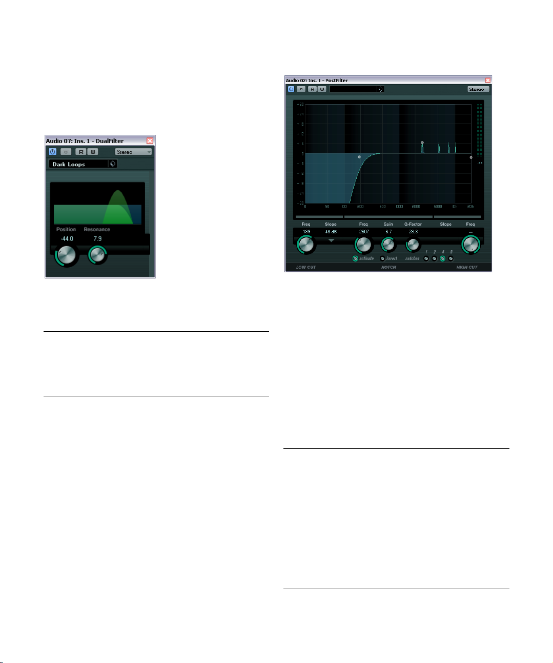
DualFilter
PostFilter
The DualFilter effect filters out certain frequencies while
allowing others to pass through.
The following parameters are available:
Parameter Description
Position Sets the filter cutoff frequency. If you set this to a nega-
Resonance Sets the sound characteristic of the filter. With higher val-
tive value, DualFilter will act as a low-pass filter. Positive
values cause DualFilter to act as a high-pass filter.
ues, a ringing sound is heard.
The PostFilter is the filter plug-in to use if you are working
on a post-production mix, but of course you can use it in
music production, too, as an alternative to complex EQ
configurations. It allows quick and easy filtering of un
wanted frequencies, creating room for the important
sounds in your mix.
The PostFilter plug-in combines a low-cut filter, a notch filter and a high-cut filter. You can either make settings by
dragging the handles in the graphical display, or by adjusting one of the controls below the display section.
Use the Preview buttons to compare the result of your filtering and the filtered frequencies.
The following parameters are available:
Parameter Description
Level meter The meter to the right of the EQ display shows the out-
Low Cut Freq
(20 Hz to 1 kHz,
or Off)
Low Cut Slope
pop-up menu
Low Cut
Preview button
put level, giving you an indication of how the filtering affects the overall level of the edited event.
Use this low-cut filter to eliminate low-frequency noise.
The filter is off when the handle/knob is moved all the
way to the left.
Allows you to choose a slope value for the low-cut filter.
Use the Preview button (found between the Low Cut
Freq button and the graphical display) to switch the fil
ter to a complementary high-cut filter. This deactivates
any other filters, allowing you to listen only to the fre
quencies you want to filter out.
-
-
The included effect plug-ins
21
Page 22
Parameter Description
Notch Freq Sets the frequency of the notch filter.
Notch Gain Allows you to adjust the gain of the selected frequency.
Notch Gain
Invert button
Notch Q-Factor Sets the width of the notch filter.
Notch Preview
button
Notches buttons
(1, 2, 4, 8)
High Cut Freq
(3 Hz to 20 kHz,
or Off)
High Cut Slope
pop-up menu
High Cut
Preview button
Use positive values to identify the frequencies that you
want to filter out.
Inverts the gain value of the notch filter. Use this button
to filter out unwanted noise. While looking for the fre
quency to omit, it sometimes helps to boost it in the first
place (set notch filter to positive gain). After you have
found it, you can use the Invert button to cancel it out.
Use the Preview button (found between the notch filter
buttons and the graphical display) to create a bandpass filter with the peak filter’s frequency and Q. This
deactivates any other filters, allowing you to listen only
to the frequencies you want to filter out.
These buttons add additional notch filters to filter out
harmonics.
Use this high-cut filter to eliminate high-frequency
noise. Filter is Off when the handle/knob is moved all
the way to the right.
Allows you to choose a slope value for the high-cut filter.
Use the Preview button (found between the High Cut
Freq button and the graphical display) to switch the fil
ter to a complementary low-cut filter. This deactivates
any other filters, allowing you to listen only to the fre
quencies you want to filter out.
-
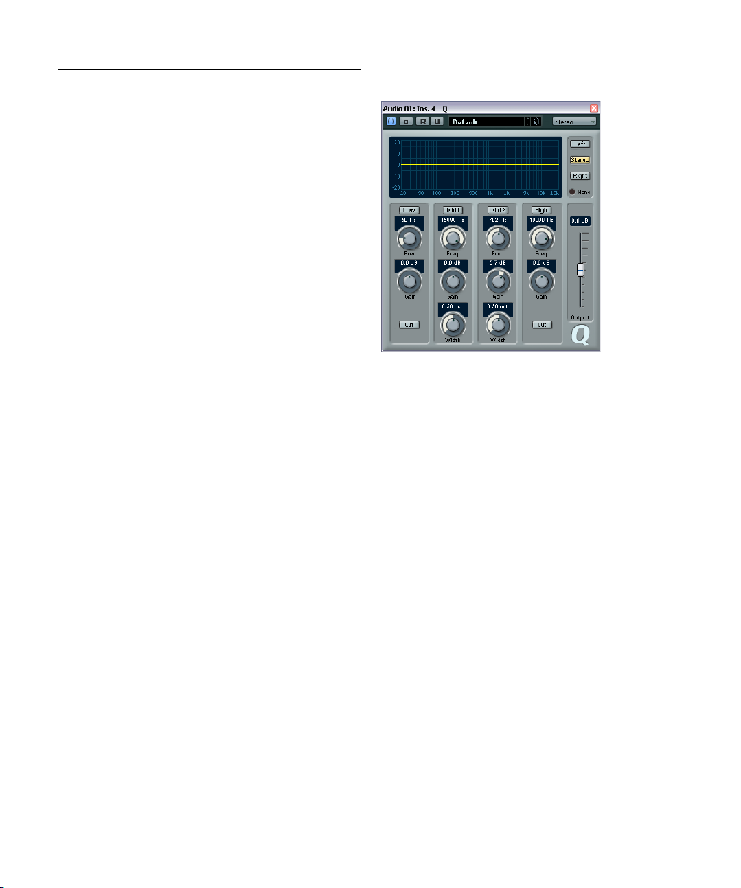
Q
-
Q is a high-quality 4-band parametric stereo equalizer
with two fully parametric mid-range bands. The low and
-
high bands can act as either standard shelving filters or
fixed-gain high/low-cut filters.
Making settings
1. Click the corresponding On button below the EQ curve
display to activate any or all of the Low, Mid 1, Mid 2, or
High equalizer bands.
When a band is activated, a corresponding EQ point appears in the EQ
curve display.
2. Set the parameters for an activated EQ band.
This can be done in several ways:
• By using the knobs.
• By clicking a value field and entering values numerically.
• By using the mouse to drag points in the EQ curve display
window.
By using this method, you control both the Gain and Frequency parameters simultaneously. The knobs turn accordingly when you drag points. In
addition, if the Mid 1 and Mid 2 bands (M1 and M2) are activated there
will be two points on each side of the Gain/Frequency point that control
the width (Q) parameter.
If you press [Shift] while dragging, values can be set in finer increments.
The included effect plug-ins
22
Page 23
The following parameters are available:
Parameter Description
Low Freq
(20 to 2000 Hz)
Low Gain
(-20 to +20 dB)
Low Cut If this button is activated for the low band, it acts as a
Mid 1 Freq
(20 to 20000 Hz)
Mid 1 Gain
(+/-20 dB)
Mid 1 Width
(0.05 to 5.00
Octaves)
Mid 2 Freq
(20 to 20000 Hz)
Mid 2 Gain
(-20 to +20 dB)
Mid 2 Width
(0.05 to 5.00
Octaves)
High Freq
(200 to 20000 Hz)
High Gain
(-20 to +20 dB)
High Cut If this button is activated for the High band, it acts as a
Output slider
(-20 to +20 dB)
Left/Stereo/Right/
Mono modes
Sets the frequency of the low band.
Sets the amount of cut/boost for the low band.
low cut filter, and the Gain parameter is fixed.
Sets the center frequency of the mid 1 band.
Sets the amount of cut/boost for the mid 1 band.
Sets the width of the mid 1 band in octaves. The
lower this value, the “narrower” the bandwidth.
Sets the center frequency of the mid 2 band.
Sets the amount of cut/boost for the mid 2 band.
Sets the width of the mid 2 band in octaves. The
lower this value, the “narrower” the bandwidth.
Sets the frequency of the high band.
Sets the amount of cut/boost for the high band.
high cut filter, and the Gain parameter is fixed.
Allows you to adjust the overall output level.
For stereo signals you can set independent curves for
the left and right channels by clicking the correspond
ing button. If the Stereo button is activated, the curve
is applied to both channels.
When channel-independent curves have been set,
the curves for the left and right channel are colored
green and red, respectively. The channel that is not
selected is shown with a dotted curve. If you activate
the Stereo button after independent curves have been
set, the active curve is applied to both channels.
Mono mode is automatically activated for mono signals and is otherwise unavailable.
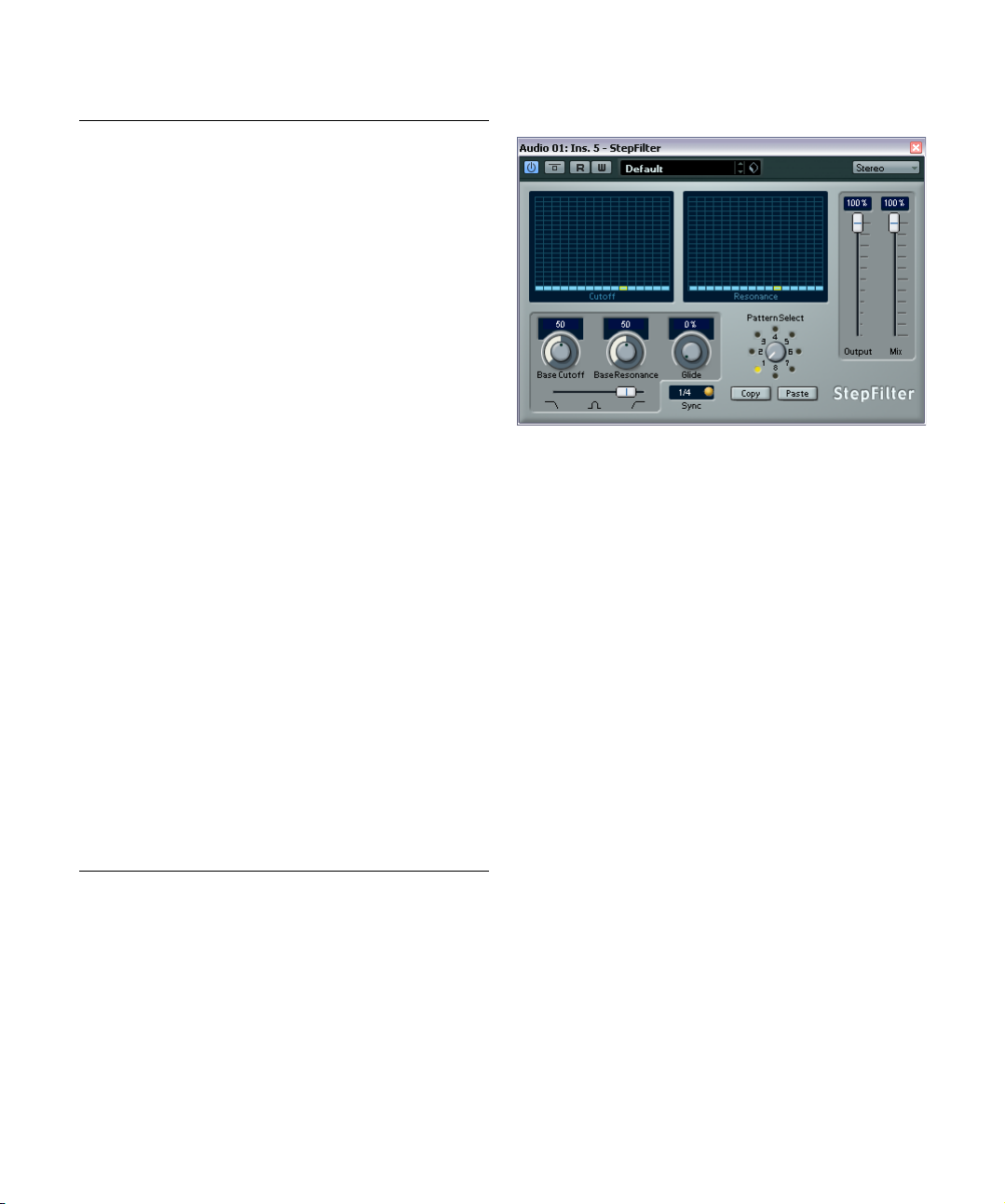
StepFilter
StepFilter is a pattern-controlled multimode filter that can
create rhythmic, pulsating filter effects.
General operation
StepFilter can produce two simultaneous 16-step patterns for the filter cutoff and resonance parameters, synchronized to the sequencer tempo.
Setting step values
• Setting step values is done by clicking in the pattern
grid windows.
• Individual step entries can be freely dragged up or
-
down the vertical axis, or directly set by clicking in an
empty grid box. By click-dragging left or right, consecutive
step entries are set at the pointer position.
• The horizontal axis shows the pattern steps 1 to 16 from
left to right, and the vertical axis determines the (relative)
filter cutoff frequency and resonance settings.
The higher up on the vertical axis a step value is entered, the higher the
relative filter cutoff frequency or filter resonance setting.
• By starting playback and editing the patterns for the cutoff and resonance parameters, you can hear how your filter
patterns affect the sound source connected to StepFilter.
The included effect plug-ins
23
Page 24
Selecting new patterns
• Created patterns are saved with the project, and up to 8
different cutoff and resonance patterns can be saved internally.
Both the cutoff and resonance settings are saved together in the 8 pattern
slots.
• Use the Pattern Selector below the Resonance grid to
select a new pattern.
New patterns are all set to the same step value by default.
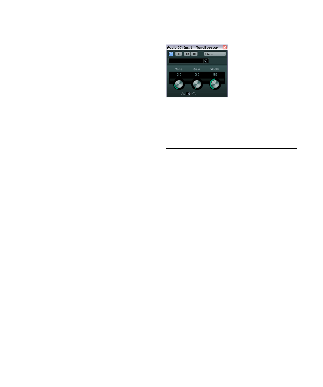
ToneBooster
Using pattern copy and paste to create variations
You can use the Copy and Paste buttons below the Pattern Selector to copy a pattern to another pattern slot,
which is useful for creating variations on a pattern.
• Select the pattern you wish to copy, click the Copy button, select another pattern slot, and click Paste.
The pattern is copied to the new slot, and can now be edited to create
variations using the original pattern as a starting point.
StepFilter parameters
Parameter Description
Base Cutoff Sets the base filter cutoff frequency. Values set in the
Base Resonance Sets the base filter resonance. Values set in the Reso-
Glide This will apply glide between the pattern step values,
Filter mode Use this slider to select a filter mode: low-pass (LP),
Sync button When the Sync button to the right of the Sync pop-up
Sync pop-up
menu (1/1 to
1/32, straight,
triplet, or dotted)
Output slider Sets the overall volume.
Mix slider Adjusts the mix between dry and processed signal.
Cutoff grid are relative to the Base Cutoff value.
nance grid are relative to the Base Resonance value.
Note that very high Base Resonance settings can pro
duce loud ringing effects at certain frequencies.
causing values to change more smoothly.
band-pass (BP), or high-pass (HP) (from left to right).
menu is activated (yellow), the pattern playback is syn
chronized with the project tempo.
Use this pop-up menu to set the pattern beat resolution,
i.
e. what note values the pattern will play in relation to the
tempo.
ToneBooster is a filter that allows you to raise the gain in a
selected frequency range. It is particularly useful when in
serted before AmpSimulator in the plug-in chain (see
“AmpSimulator” on page 9), greatly enhancing the tonal
varieties available.
The following parameters are available:
Parameter Description
Tone Sets the center filter frequency.
Gain Allows you to adjust the gain of the selected frequency
Width Sets the resonance of the filter.
Mode selector Sets the basic operational mode of the filter; Peak or
-
-
range by up to 24
Band Mode.
dB.
-
The included effect plug-ins
24
Page 25
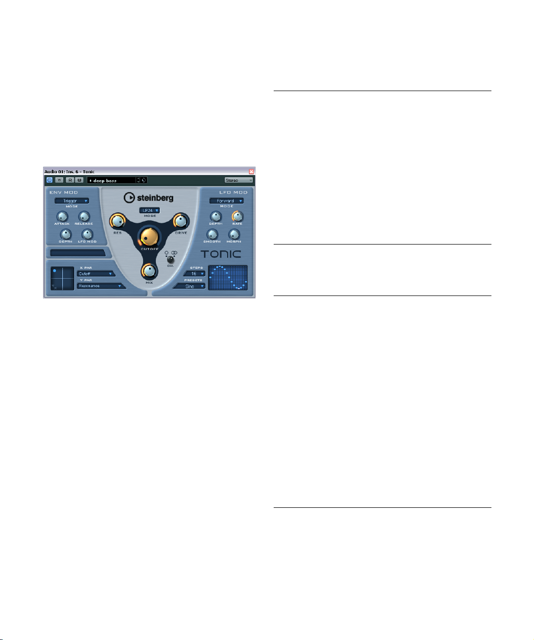
Tonic
Tonic is a versatile and powerful analog modeling filter
plug-in based on the filter design of the Monologue monophonic synthesizer. Its variable characteristics plus the
powerful modulation functions make it an excellent choice
for all current music styles. Designed to be more a cre
ative tool rather than a tool to fix audio problems, it can
add color and punch to your tracks while being light on
CPU usage.
Tonic has the following properties:
• Dynamic multimode analog modeling filter (mono/stereo).
• 24 dB low-pass, 18 dB low-pass, 12 dB low-pass, 6 dB
low-pass, 12 dB band-pass, and 12 dB high-pass modes.
• Adjustable drive and resonance up to self-oscillation.
• Envelope follower for dynamic filter control with an
audio signal.
• Audio and MIDI trigger modes.
• Powerful step LFO with smoothing and morphing.
• X/Y matrix pad for additional realtime modulation with
access to all Tonic parameters.
-
Filter
In the Filter section at the center of the plug-in panel, the
following parameters are available:
Parameter Description
Mode pop-up
menu
Cutoff Sets the filter cutoff frequency. How this parameter oper-
Res Changes the resonance of the multi-mode filter. Full res-
Drive Adds a soft, tube-like saturation to the sound. As with an
Mix Sets the balance between dry and effect signal.
Channel
selector (Ch.).
Sets the filter type. Available filter types are: 24 dB low-
dB low-pass, 12 dB low-pass, 6 dB low-pass,
pass, 18
dB band-pass, and 12 dB high-pass.
12
ates is governed by the filter type.
onance puts the filter into self-oscillation.
analog filter, the amount of saturation also depends on
the input signal level.
Allows you to choose between mono or stereo operation.
When set to mono, the output signal of Tonic is mono re
gardless of the input signal.
Env Mod
In the Env Mod section, the following parameters are
available:
Parameter Description
Mode pop-up
menu
Attack Controls the attack time of the envelope. Higher attack
Release Controls the release time of the envelope. Higher release
Depth Controls the amount of envelope control applied to the
LFO Mod Using this parameter, the envelope level modulates the
Tonic offers three types of envelope modulation:
“Follow” tracks the input signal’s volume envelope for dynamic control of the filter cutoff.
“Trigger” uses the input signal to trigger the envelope and
have it run through a single envelope cycle.
“MIDI” uses any MIDI note to trigger the envelope. The filter cutoff tracks the keys played on the keyboard. In addition, velocities higher than 80 add an accent to the
envelope by increasing the envelope depth and reducing
the decay time.
For MIDI control, set up a separate MIDI control track and
select “Tonic” from the Output Routing pop-up menu for
the track.
times result in slower rise times when the envelope is trig
gered.
times result in slower envelope tails.
filter cutoff level.
LFO speed. A rather stunning effect.
-
-
The included effect plug-ins
25
Page 26
X/Y Pad
In the X/Y Pad at the bottom left of the plug-in panel, the
following parameters are available:
Parameter Description
X Par pop-up
menu
Y Par pop-up
menu
XY Pad Use the mouse to control any two of Tonic’s parameters
Sets the parameter to be modulated on the x-axis of the
XY Pad. All of Tonic’s parameters are available as desti
nations.
Sets the parameter to be modulated on the y-axis of the
XY Pad.
in combination. By moving the mouse horizontally you
control the x parameter, and by moving it vertically you
control the y parameter. You can also record controller
movements as automation data.
LFO Mod
In the LFO Mod section, the following parameters are
available:
Parameter Description
Mode pop-up
menu
Depth Controls the amount of LFO modulation applied to the fil-
Rate Controls the speed of the LFO modulation. The LFO rate
Smooth Controls the smoothing of the LFO steps. This works like
Morph Controls the playback value of the LFO step sequencer. It
Steps pop-up
menu
Presets
pop-up menu
Step Matrix Click into the Step Matrix to set the level for each of the
Sets the direction of the step LFO modulation. The available modes are: Forward, Reverse, Alternating, and Random.
ter cutoff level.
is always in sync with the project tempo. An example: at a
rate of 4.00 steps per beat in a 4/4 time signature, the
step sequencer advances in 16th notes. At a rate of 4.00
beats per step in a 4/4 time signature the LFO advances
only one step per bar.
Note that the current LFO Rate is shown in the field below the Env Mod section.
a glide effect applied to the filter cutoff.
makes the LFO steps drift about randomly. Experiment
freely with the Morph parameter. As you return the knob
to its zero position, the step pattern returns to its original
setting.
Sets the number of steps played in sequence. Deactivated steps are grayed out in the Step Matrix.
Offers a number of step LFO waveform patterns. Choices
include: Sine, Sine+, Cosine, Triangle, Sawtooth,
Square, Random, and User (which is the pattern saved
with the respective program).
16 LFO steps. A higher amount results in a deeper filter
cutoff modulation. Click and drag along the matrix to
“draw” a waveform.
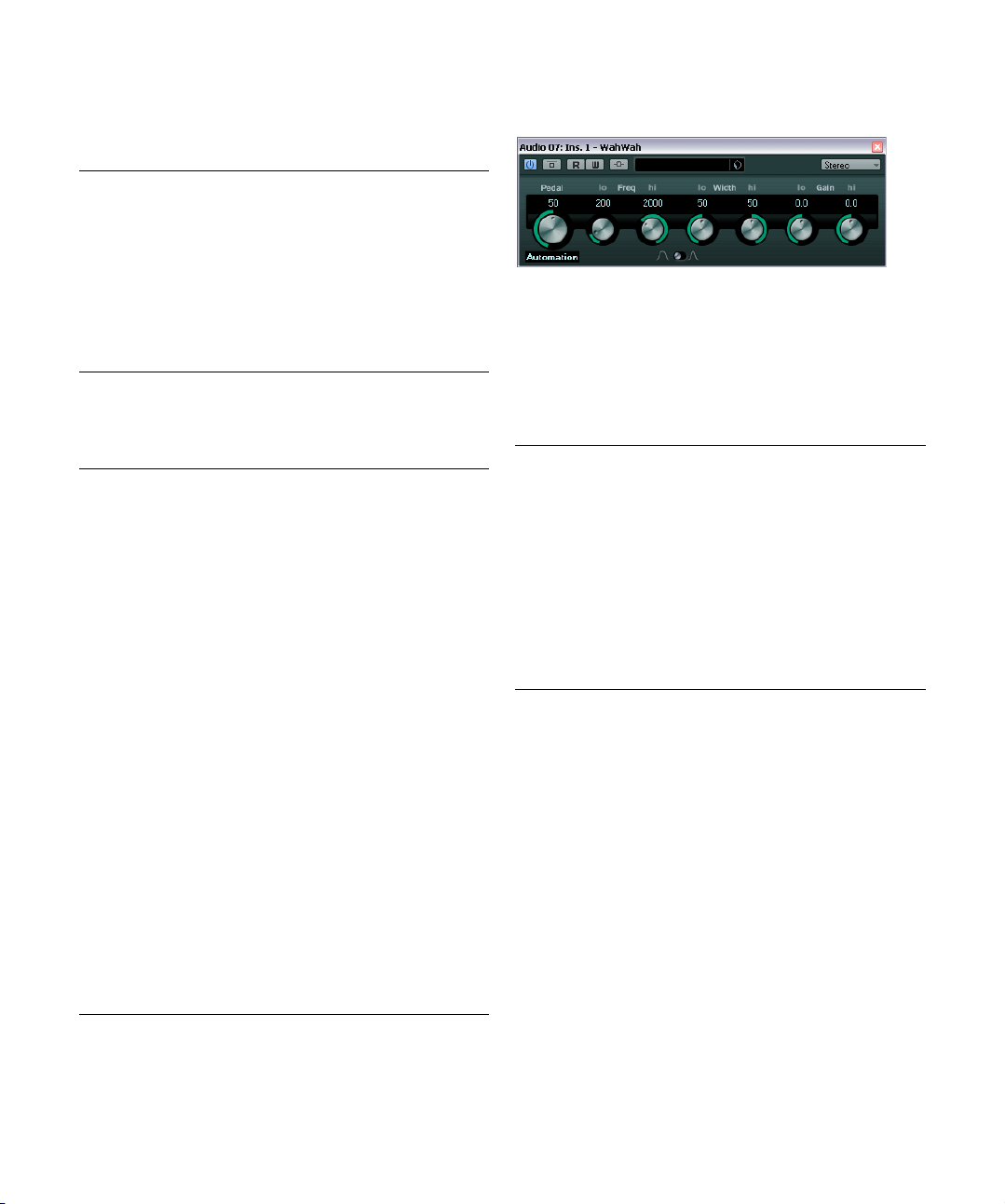
WahWah
-
WahWah is a variable slope band-pass filter that can be
auto-controlled by a side-chain signal or via MIDI model
ing the well-known analog pedal effect (see below). You
can independently specify the frequency, width and the
gain for the Lo and Hi Pedal positions. The crossover
point between the Lo and Hi Pedal positions lies at 50.
The following parameters are available:
Parameter Description
Pedal Controls the filter frequency sweep.
Pedal Control
(MIDI) pop-up
menu
Freq Lo/Hi Set the frequency of the filter for the Lo and Hi Pedal po-
Width Lo/Hi Set the width (resonance) of the filter for the Lo and Hi
Gain Lo/Hi Set the gain of the filter for the Lo and Hi Pedal positions.
Filter Slope
selector
When the side-chain input is activated, a signal routed
to the side-chain input of the effect can control the Pedal
parameter. The louder the signal, the more the filter frequency (Pedal) is raised so that the plug-in acts as an
“auto-wha” effect. For a description of how to set up sidechain routing, see the chapter “Audio effects” in the Operation Manual.
MIDI control
For realtime MIDI control of the Pedal parameter, MIDI
must be directed to the WahWah plug-in.
• Whenever WahWah has been added as an insert effect
(for an audio track or an FX channel), it is available on the
Output Routing pop-up menu for MIDI tracks.
If WahWah is selected on the Output Routing menu, MIDI data is directed
to the plug-in from the selected track.
Allows you to choose the MIDI controller that is used to
control the plug-in. Set this to “Automation” if you do not
want to use MIDI realtime control.
sitions.
Pedal positions.
Allows you to choose between two filter slope values:
dB or 12 dB.
6
-
The included effect plug-ins
26
Page 27
Generator plug-ins
This section contains descriptions of the plug-ins in the
“Generator” category.
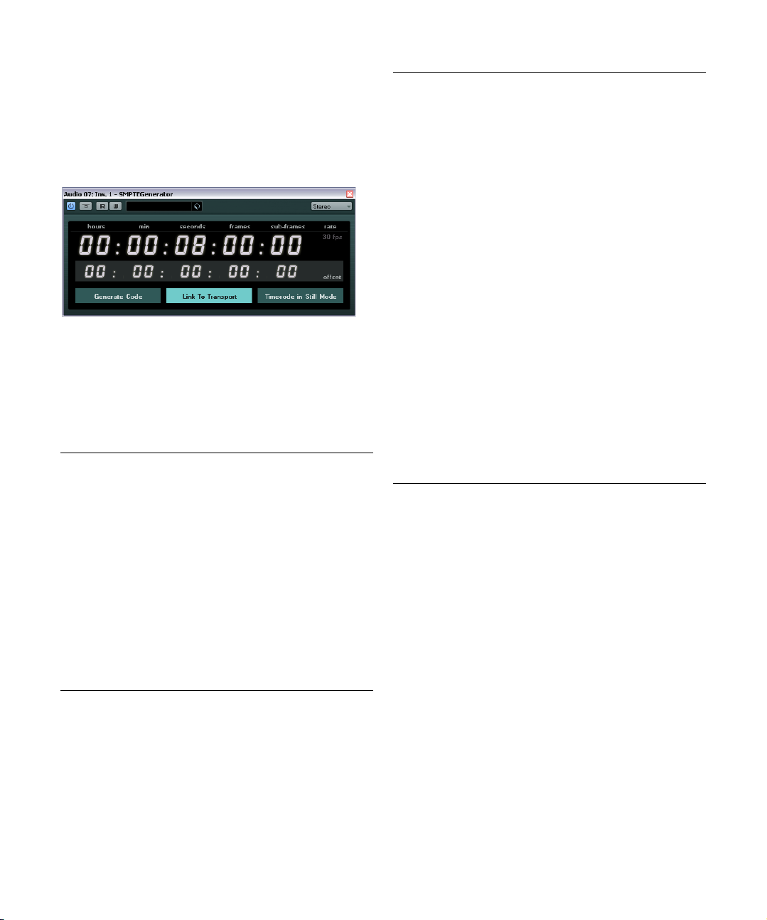
SMPTEGenerator
This plug-in is not a real audio effect. It sends out SMPTE
timecode to an audio output, allowing you to synchronize
other equipment to Nuendo (provided that the equipment
can sync directly to SMPTE timecode). This can be very
useful if you do not have access to a MIDI-to-timecode
converter.
The following parameters are available:
Parameter Description
Main timecode
display
Frame rate
display and
pop-up menu
This display shows the current timecode.
When “Link to Transport” is deactivated, the generator is
in “free run” mode. You can then use the timecode dis
play to set the SMPTE start time.
When “Link to Transport” is activated, you cannot change
any of the values. This display shows the current time
code in sync with the Transport panel. Where applicable,
the offset defined in the offset timecode display is taken
into account (see below).
The frame rate shown to the right of the timecode display
defaults to the frame rate set in the Project Setup dialog.
To generate timecode in a different frame rate (e.
stripe a tape), select another format on the pop-up menu
(only available if “Link to Transport” is deactivated).
Note that for another device to synchronize correctly to
Nuendo, the same frame rate has to be set in the Project
Setup dialog, the SMPTE Generator and the receiving
device.
-
-
g. to
Parameter Description
Offset
timecode
display
Generate
Code button
Link to
Transport
button
Timecode in
Still Mode
button
This display is only available if “Link to Transport” is activated. It allows you to set an offset with regard to the timecode used by Nuendo. The offset affects the generated
SMPTE signal, the current cursor position in Nuendo re
mains unaffected.
For example, use this when playing back video using an
external device, where the video starts at a different time
code position than in Nuendo. A scenario could be as follows: Your have placed the same video several times on
the Nuendo timeline, in order to record different audio
versions for that video one after the other. However, since
video playback is done via an external machine (replaying
the same video) you need an offset to match the different
timecode positions in Nuendo with the (unchanging) start
position on the external machine.
When you activate this button, the plug-in generates
SMPTE timecode in “free run” mode, meaning that it out
puts continuous timecode independent from the Transport panel. Use this mode if you want to stripe tape with
SMPTE.
When you activate this button, the timecode is synchronized to the Transport panel.
When you activate this button, the plug-in also generates
SMPTE timecode in stop mode. However, note that this
will not be continuous timecode, but timecode generated
at the current cursor position.
For example, this can be useful when working with video
editing software that interprets the absence of timecode
as a stop command. By using this option, the video soft
ware can enter still mode instead so that a still frame is
shown instead of a blank screen.
-
To change one of the timecode values (main and offset timecode displays), double-click on any of the timecode fields and enter a new value.
Example – Synchronizing a device to Nuendo
1. Use the SMPTE Generator as an insert effect on an
audio track, and route that track to a separate output.
Make sure that no other insert or send effect is used on this track. You
should also disable any EQ.
2. Connect the corresponding output on the audio hardware to the timecode input on the device you wish to synchronize to Nuendo.
Make all necessary settings for the external device so that it synchronizes
to incoming timecode.
3. If needed, adjust the level of the timecode, either in
Nuendo or in the receiving device.
Activate the Generate Code button (make the device send the SMPTE
timecode in “free run” mode) to test the level.
-
-
-
The included effect plug-ins
27
Page 28

4. Make sure that the frame rate in the receiving device
!
matches the frame rate set in the SMPTE Generator.
5. Activate the “Link to Transport” button.
The SMPTE Generator now outputs timecode that corresponds to the
Nuendo time display.
6. On the Nuendo Transport panel, click Play.
The external device is now synchronized and will follow any position
changes set with the Nuendo transport controls.
Parameter Description
Frequency
section
Gain section Allows you to set the amplitude of the signal. The higher
Allows you to set the frequency of the generated signal.
You can select one of the preset values (100, 440, 1000,
Hz), or use the slider to set a value between
or 10000
Hz and 20000 Hz.
1
the value (up to 0
select one of the preset values (e.
slider to set a value between -81 and 0
dB), the stronger the signal. You can
g. -20 dB), or use the
dB.
TestGenerator
This utility plug-in allows you to generate an audio signal,
which can be recorded as an audio file. The resulting file
can then be used for a number of purposes:
• For testing the specifications of audio equipment.
• For measurements of various kinds, such as calibrating tape
recorders.
• For testing signal processing methods.
• For educational purposes.
The TestGenerator is based on a waveform generator
which can generate a number of basic waveforms such as
sine and saw as well as various types of noise. Furthermore, you can set the frequency and amplitude of the generated signal.
As soon as you add the TestGenerator as an effect on an
audio track and activate it, a signal is generated. You can
then activate recording as usual to record an audio file according to the signal specifications:
Parameter Description
Waveforms
and noise
section
Allows you to set the basis for the signal generated by the
waveform generator. You can select between four basic
waveforms (sine, triangle, square, and sawtooth) and
three types of noise (white, pink, and brownian).
Mastering – UV22HR
The UV22HR is a dithering plug-in, based on an advanced
algorithm developed by Apogee. For an introduction to the
concept of dithering, see the chapter “Audio effects” in
the Operation Manual.
The following parameters are available:
Option Description
Bit Resolution The UV22HR supports dithering to multiple resolutions:
Hi Try this first, it is the most “all-round” setting.
Lo This applies a lower level of dither noise.
Auto black When this is activated, the dither noise is gated (muted)
Dithering should always be applied post-fader on an
output bus.
8, 16, 20 or 24 bits. You select the desired resolution by
clicking the corresponding button.
during silent passages in the material.
The included effect plug-ins
28
Page 29

Modulation plug-ins
This section contains descriptions of the plug-ins in the
“Modulation” category.
AutoPan
This is a simple auto-pan effect. It can use different waveforms to modulate the left-right stereo position (pan), either
using tempo sync or manual modulation speed settings.
The following parameters are available:
Parameter Description
Rate If tempo sync is on, this is where you specify the base
Sync button The button below the Rate knob is used to switch tempo
Width Sets the depth of the auto-pan effect.
Waveform
Shape selector
The Width parameter can also be controlled from another signal source via the side-chain input. For a description of how to set up side-chain routing, see the chapter
“Audio effects” in the Operation Manual.
note value for tempo-syncing the effect (1/1 to 1/32,
straight, triplet, or dotted).
If tempo sync is off, the auto-pan speed can be set freely
with the Rate knob.
sync on or off.
Allows you to select the modulation waveform. A sine and
a triangle waveform are available.
Chorus
This is a single stage chorus effect. It works by doubling
whatever is sent into it with a slightly detuned version (see
also “StudioChorus” on page 34).
The following parameters are available:
Parameter Description
Rate If tempo sync is on, this is where you specify the base
Sync button The button below the Rate knob is used to switch tempo
Width Determines the depth of the chorus effect. Higher set-
Waveform
Shape selector
Spatial Sets the stereo width of the effect. Turn clockwise for a
Mix Sets the level balance between the dry signal and the ef-
Delay Affects the frequency range of the modulation sweep by
Filter Lo/Hi Allow you to roll off low and high frequencies of the effect
note value for tempo syncing the chorus sweep (1/1 to
1/32, straight, triplet, or dotted).
If tempo sync is off, the sweep rate can be set freely with
the Rate knob.
sync on or off.
tings produce a more pronounced effect.
Allows you to select the modulation waveform, altering
the character of the chorus sweep. A sine and a triangle
waveform are available.
wider stereo effect.
fect. If Chorus is used as a send effect, set this to the
maximum value as you can control the dry/effect balance
with the send.
adjusting the initial delay time.
signal.
The included effect plug-ins
29
Page 30

The modulation can also be controlled from another signal source via the side-chain input. When the side-chain
signal exceeds the threshold, the modulation is controlled
by the side-chain signal’s envelope. For a description of
how to set up side-chain routing, see the chapter “Audio ef
fects” in the Operation Manual.
Cloner
The Cloner plug-in adds up to four detuned and delayed
voices to the signal, for rich modulation and chorus effects.
The following parameters are available:
Parameter Description
Voices Allows you to select the number of voices (up to four). For
Spatial Spreads the added voices across the stereo spectrum.
Mix Sets the level balance between the dry signal and the ef-
Output Allows you to reduce or increase the output gain by up to
Detune slider
1–4
Delay slider
1–4
Detune Governs the overall depth of the detuning for all voices. If
Natural button By clicking the Natural button below the Detune knob,
Detune –
Humanize
each added voice, a Detune and a Delay slider are added
in the right half of the panel.
Turn clockwise for a deeper stereo effect.
fect. If Cloner is used as a send effect, set this to the maximum value as you can control the dry/effect balance with
the send.
dB.
12
Controls the relative detune amount for each voice. Positive and negative values can be set, from -100 to 100. A
value of zero means no detune for that voice.
Controls the relative delay amount for each voice. A value
of zero means no delay for that voice.
this is set to zero, no detuning takes place, regardless of
the Detune slider settings.
you can change the pitch algorithm.
Controls the amount of detune variation when Static Detune is deactivated. With Humanize, the detune is constantly modulated for a more natural effect. The value
range is from 0 to 100 (strongest detune variation).
Parameter Description
Static Detune
button
Delay Governs the overall depth of the delay for all voices. If set
-
Delay –
Humanize
Static Delay
button
Use this button to activate/deactivate the Static Detune
function. If activated, the set detune amount is static, and
the Humanize knob is grayed out.
to zero, no delay takes place regardless of the Delay
slider settings.
Controls the amount of delay variation when Static Detune is deactivated. With Humanize, the delay is constantly modulated for a more natural effect. The value
range is from 0 to 100 (strongest delay variation).
Use this button to activate/deactivate the Static Delay
function. If activated, the set delay amount is static, and
the Humanize knob is grayed out.
Flanger
Flanger is a classic flanger effect with added stereo
enhancement.
The following parameters are available:
Parameter Description
Rate If tempo sync is on, this is where you specify the base
Sync button The button below the Rate knob is used to switch tempo
Range Lo/Hi Set the frequency boundaries for the flanger sweep.
Feedback Determines the character of the flanger effect. Higher
Spatial Sets the stereo width of the effect. Turn clockwise for a
note value for tempo syncing the flanger sweep (1/1 to
1/32, straight, triplet, or dotted).
If tempo sync is off, the sweep rate can be set freely with
the Rate knob.
sync on or off.
settings produce a more “metallic” sounding sweep.
wider stereo effect.
The included effect plug-ins
30
Page 31

Parameter Description
Mix Sets the level balance between the dry signal and the ef-
Waveform
Shape selector
Delay Affects the frequency range of the modulation sweep by
Manual knob Allows you to change the sweep position manually when
Manual button Use this button to activate/deactivate the Manual func-
Filter Lo/Hi Allow you to roll off low and high frequencies of the effect
fect. If Flanger is used as a send effect, set this to the
maximum value as you can control the dry/effect balance
with the send.
Allows you to select the modulation waveform, altering
the character of the flanger sweep. A sine and a triangle
waveform are available.
adjusting the initial delay time.
the Manual button is deactivated. The value range is from
0 to 100.
tion. If activated, the flanger sweep is static, i. e. no modulation takes place.
signal.
The modulation can also be controlled from another
signal source via the side-chain input. When the sidechain signal exceeds the threshold, the modulation is con
trolled by the side-chain signal’s envelope. For a description of how to set up side-chain routing, see the chapter
“Audio effects” in the Operation Manual.
Metalizer
Metalizer feeds the audio signal through a variable frequency filter, with tempo sync or time modulation and
feedback control.
-
Parameter Description
Feedback The higher the value, the more “metallic” the sound.
Sharpness Governs the character of the filter effect. The higher the
Tone Governs the feedback frequency. The effect of this will be
On button Turns filter modulation on and off. When turned off, Met-
Mono button When this is activated, the output of Metalizer is mono.
Speed If tempo sync is on, this is where you specify the base
Sync button The button above the Speed knob is used to switch
Output slider Sets the overall volume.
Mix slider Sets the level balance between the dry signal and the ef-
value, the narrower the affected frequency area, produc
ing a sharper sound and a more pronounced effect.
more noticeable with high Feedback settings.
alizer works as a static filter.
note value for tempo-syncing the effect (1/1 to 1/32,
straight, triplet, or dotted). Note that there is no note
value modifier for this effect.
If tempo sync is off, the modulation speed can be set
freely with the Speed knob.
tempo sync on (button lights up) or off.
fect. If Metalizer is used as a send effect, set this to the
maximum value as you can control the dry/effect balance
with the send.
-
The included effect plug-ins
31
Page 32

Phaser
Phaser produces the well-known “swooshing” phasing
effect with additional stereo enhancement.
The following parameters are available:
Parameter Description
Rate If tempo sync is on, this is where you specify the base note
Sync button The button below the Rate knob is used to switch tempo
Width Determines the width of the modulation effect between
Feedback Determines the character of the phaser effect. Higher
Spatial When using multi-channel audio, the Spatial parameter
Mix Sets the level balance between the dry signal and the ef-
Manual knob Allows you to change the sweep position manually when
Manual button Use this button to activate/deactivate the Manual func-
Filter Lo/Hi Allow you to roll off low and high frequencies of the effect
value for tempo syncing the phaser sweep (1/1 to 1/32,
straight, triplet, or dotted).
If tempo sync is off, the sweep rate can be set freely with
the Rate knob.
sync on or off.
higher and lower frequencies.
settings produce a more pronounced effect.
creates a 3-dimensional impression by delaying modula
tion in each channel.
fect. If Phaser is used as a send effect, set this to the
maximum level as you can control the dry/effect balance
with the send.
the Manual button is deactivated. The value range is from
0 to 100.
tion. If activated, the flanger sweep is static, i. e. no modulation takes place.
signal.
The modulation can also be controlled from another
signal source via the side-chain input. When the sidechain signal exceeds the threshold, the modulation is con
trolled by the side-chain signal’s envelope. For a description of how to set up side-chain routing, see the chapter
“Audio effects” in the Operation Manual.
RingModulator
RingModulator can produce complex, bell-like enharmonic
sounds. Ring modulators work by multiplying two audio
signals. The ring modulated output contains added fre
quencies generated by the sum of, and the difference between, the frequencies of the two signals.
RingModulator has a built-in oscillator that is multiplied
with the input signal to produce the effect.
-
The following parameters are available:
Parameter Description
Oscillator –
LFO Amount
Oscillator –
Env. Amount
Oscillator –
Waveform
buttons
Oscillator –
Range slider
Controls how much the oscillator frequency is affected by
the LFO.
Controls how much the oscillator frequency is affected by
the envelope (which is triggered by the input signal). Pos
itive and negative values can be set, with center position
representing no modulation. Left of center, a loud input
signal will decrease the oscillator pitch, whereas right of
center the oscillator pitch will increase when fed a loud
input.
Allows you to select the oscillator waveform; square, sine,
saw, or triangle.
Determines the frequency range of the oscillator in Hz.
-
-
-
The included effect plug-ins
32
Page 33

Parameter Description
Oscillator –
Frequency
Oscillator –
Roll-Off
LFO – Speed Sets the LFO speed.
LFO –
Amount
Env.
LFO –
Waveform
LFO – Invert
Stereo
Envelope
Generator
section –
Attack and
Decay
Lock L<R
button
Output slider Sets the overall volume.
Mix slider Adjusts the mix between dry and processed signal.
Sets the oscillator frequency +/- 2 octaves within the selected range.
Cuts high frequencies in the oscillator waveform, to
soften the overall sound. This is best used when harmon
ically rich waveforms are selected (e. g. square or saw).
Controls how much the input signal level – via the envelope generator – affects the LFO speed. Positive and
negative values can be set, at 0
plied. With negative values, a loud input signal slows
down the LFO, whereas positive values are used to
speed it up at loud input signals.
Allows you to select the LFO waveform; square, sine,
saw, or triangle.
Inverts the LFO waveform for the right channel of the oscillator, which produces a wider stereo perspective for
the modulation.
The Envelope Generator section controls how the input
signal is converted to envelope data, which can then be
used to control oscillator pitch and LFO speed. It has two
main controls:
Attack controls how fast the envelope output level rises in
response to a rising input signal.
Decay controls how fast the envelope output level falls in
response to a falling input signal.
When this button is enabled, the L and R input signals
are merged, and produce the same envelope output level
for both oscillator channels. When disabled, each chan
nel has its own envelope, which affects the two channels
of the oscillator independently.
% no modulation is ap-
Rotary
The Rotary plug-in simulates the classic effect of a rotating speaker. A rotary speaker cabinet features speakers
rotating at variable speeds to produce a swirling chorus
effect, commonly used with organs. Rotary features all the
parameters associated with the real thing.
The following parameters are available:
Parameter Description
Speed selector (Stop/
-
Slow/Fast)
Speed
Change Mode
Speed Mod When the Slow/Fast setting is set to variable control, this
MIDI controller
pop-up menu
Overdrive Applies a soft overdrive or distortion.
CrossOver Sets the crossover frequency (200 to 3000 Hz) between
Horn – Slow Allows for a fine adjustment of the high rotor Slow speed.
Horn – Fast Allows for a fine adjustment of the high rotor Fast speed.
Horn – Accel. Allows for a fine adjustment of the high rotor acceleration
Horn –
Amp
Mod
Horn –
Mod
Freq
Bass – Slow Allows for a fine adjustment of the low rotor Slow speed.
Bass – Fast Allows for a fine adjustment of the low rotor Fast speed.
Bass – Accel. Allows for a fine adjustment of the low rotor acceleration
Bass –
Amp
Mod
Bass – Level Adjusts the overall bass level.
Microphones –
Phase
Microphones –
Angle
Microphones –
Distance
Output Allows you to adjust the overall output level.
Mix Allows you to adjust the mix between dry and processed
Allows you to control the speed of the Rotary in three
steps.
Allows you to select whether the Slow/Fast setting is a
switch (left) or a variable control (right). When switch
mode is selected and Pitchbend is the controller, the
speed will switch with an up or down flick of the bender.
Other controllers switch at MIDI value 64.
allows you to select the rotary speed, from 0 (Stop) to
100 (Fast).
Allows you to choose the MIDI controller that is used to
control the plug-in. Set this to “Automation” if you do not
want to use MIDI realtime control.
the low and high frequency loudspeakers.
time.
Controls the high rotor amplitude modulation.
Controls the high rotor frequency modulation.
time.
Adjusts the modulation depth of the amplitude.
Allows you to adjust the phasing amount in the sound of
the high rotor.
Sets the simulated microphone angle. 0 = mono, 180 =
one mic on each side.
Sets the simulated microphone distance from the
speaker in inches.
signals.
Directing MIDI to the Rotary
For realtime MIDI control of the Speed parameter, MIDI
must be directed to the Rotary.
The included effect plug-ins
33
Page 34

• Whenever Rotary has been added as an insert effect
(for an audio track or an FX channel), it is available on the
Output Routing pop-up menu for MIDI tracks.
If Rotary is selected on the Output Routing menu, MIDI is directed to the
plug-in from the selected track.
StudioChorus
The StudioChorus plug-in is a two stage chorus effect
which adds short delays to the signal and pitch modulates
the delayed signals to produce a “doubling” effect. The
two separate stages of chorus modulation are completely
independent and are processed serially (cascaded).
For each stage the following parameters are available:
Parameter Description
Rate If tempo sync is on, this is where you specify the base
Sync button The button below the Rate knob is used to switch
Width Determines the depth of the chorus effect. Higher set-
Waveform
Shape selector
Spatial Sets the stereo width of the effect. Turn clockwise for a
Mix Sets the level balance between the dry signal and the
Delay Affects the frequency range of the modulation sweep
Filter Lo/Hi Allow you to roll off low and high frequencies of the ef-
note value for tempo syncing the chorus sweep (1/1 to
1/32, straight, triplet, or dotted).
If tempo sync is off, the sweep rate can be set freely
with the Rate knob.
tempo sync on or off.
tings produce a more pronounced effect.
Allows you to select the modulation waveform, altering
the character of the chorus sweep. A sine and a trian
gle waveform are available.
wider stereo effect.
effect. If StudioChorus is used as a send effect, set this
to the maximum value as you can control the dry/effect
balance with the send.
by adjusting the initial delay time.
fect signal.
-
The modulation can also be controlled from another
signal source via the side-chain input. When the sidechain signal exceeds the threshold, the modulation is con
trolled by the side-chain signal’s envelope. For a description of how to set up side-chain routing, see the chapter
“Audio effects” in the Operation Manual.
Tranceformer
Tranceformer is a ring modulator effect, in which the incoming audio is ring modulated by an internal, variable frequency oscillator, producing new harmonics. A second
oscillator can be used to modulate the frequency of the
first oscillator, in sync with the Song tempo if needed.
The following parameters are available:
Parameter Description
Waveform
buttons
Tone Sets the frequency (pitch) of the modulating oscillator
Depth Governs the depth of the pitch modulation.
Speed If tempo sync is on, this is where you specify the base
Sync button The button above the Speed knob is used to switch
On button Turns modulation of the pitch parameter on or off.
Mono button Governs whether the output is stereo or mono.
Allow you to select a pitch modulation waveform.
to 5000 Hz).
(1
note value for tempo-syncing the effect (1/1 to 1/32,
straight, triplet, or dotted). Note that there is no note
value modifier for this effect. If tempo sync is off, the mod
ulation speed can be set freely with the Speed knob.
tempo sync on (button lights up) or off.
-
-
The included effect plug-ins
34
Page 35

Parameter Description
Output slider Allows you to adjust the output level of the effect.
Mix slider Sets the level balance between the dry signal and the
effect.
Note that clicking and dragging in the display allows
you to adjust the Tone and Depth parameters at the same
time!
Tremolo
Tremolo produces amplitude (volume) modulation. The
following parameters are available:
Parameter Description
Rate If tempo sync is on, this is where you specify the base
Sync button The button below the Rate knob is used to switch tempo
Depth Governs the depth of the amplitude modulation.
Spatial Adds a stereo effect to the modulation.
Output Allows you to adjust the output volume.
note value for tempo-syncing the effect (1/1 to 1/32,
straight, triplet, or dotted).
If tempo sync is off, the modulation speed can be set
freely with the Rate knob.
sync on or off.
Vibrato
The Vibrato plug-in produces pitch modulation. The following parameters are available:
Parameter Description
Rate If tempo sync is on, this is where you specify the base
Sync button The button below the Rate knob is used to switch tempo
Depth Governs the depth of the pitch modulation.
Spatial Adds a stereo effect to the modulation.
The modulation can also be controlled from another
signal source via the side-chain input. When the sidechain signal exceeds the threshold, the modulation is con
trolled by the side-chain signal’s envelope. For a description of how to set up side-chain routing, see the chapter
“Audio effects” in the Operation Manual.
note value for tempo-syncing the effect (1/1 to 1/32,
straight, triplet, or dotted).
If tempo sync is off, the modulation speed can be set
freely with the Rate knob.
sync on or off.
-
The modulation can also be controlled from another
signal source via the side-chain input. When the sidechain signal exceeds the threshold, the modulation is con
trolled by the side-chain signal’s envelope. For a description of how to set up side-chain routing, see the chapter
“Audio effects” in the Operation Manual.
The included effect plug-ins
-
35
Page 36

Other plug-ins
This section contains descriptions of the plug-ins in the
“Others” category.
BitCrusher
If you are into lo-fi sound, BitCrusher is the effect for you.
It offers the possibility of decimating and truncating the input audio signal by bit reduction, to get a noisy, distorted
sound. You can for example make a 24-bit audio signal
sound like an 8 or 4-bit signal, or even render it completely
garbled and unrecognizable.
The following parameters are available:
Parameter Description
Mode Allows you to select one of the four operating modes of
Sample Divider Sets the amount by which the audio samples are deci-
Depth Defines the bit resolution. A setting of 24 gives the highest
Output slider Governs the output level from BitCrusher. Drag the slider
Mix slider Regulates the balance between the output from Bit-
BitCrusher. In each mode the plug-in sounds differently.
Modes I and III are nastier and noisier, while modes II and
IV are more subtle.
mated. At the highest setting (65), nearly all of the information describing the original audio signal is eliminated,
turning the signal into unrecognizable noise.
audio quality, while a setting of 1 creates mostly noise.
upwards to increase the level.
Crusher and the original audio signal. Drag the slider upwards for a more dominant effect, and downwards if you
want the original signal to be more prominent.
Chopper
Chopper is a combined tremolo and autopan effect. It can
use different waveforms to modulate the level (tremolo) or
left-right stereo position (pan), either using tempo sync or
manual modulation speed settings. The following parame
ters are available:
Parameter Description
Waveform
buttons
Depth Sets the depth of the Chopper effect. This can also be
Speed If tempo sync is on, this is where you specify the base
Sync button The button above the Speed knob is used to switch
Stereo/Mono
button
Mix Sets the level balance between the dry signal and the ef-
Set the modulation waveform.
set by clicking in the graphical display.
note value for tempo-syncing the effect (1/1 to 1/32,
straight, triplet, or dotted). Note that there is no note
value modifier for this effect.
If tempo sync is off, the tremolo/auto-pan speed can be
set freely with the Speed knob.
tempo sync on (button lights up) or off.
Determines whether the Chopper works as an auto-panner (button set to “Stereo”) or a tremolo effect (button set
to “Mono”).
fect. If Chopper is used as a send effect, this should be
set to the maximum value.
-
The included effect plug-ins
36
Page 37

Octaver
This plug-in can generate two additional voices that track
the pitch of the input signal one octave and two octaves
below the original pitch, respectively. Octaver is best used
with monophonic signals. The following parameters are
available:
Parameter Description
Direct Adjusts the mix of the original signal and the generated
Octave 1 Adjusts the level of the generated signal one octave be-
Octave 2 Adjusts the level of the generated signal two octaves be-
voice(s). A value of 0 means only the generated and
transposed signal is heard. By raising this value, more of
the original signal is heard.
low the original pitch. Set to 0 means the voice is muted.
low the original pitch. Set to 0 means the voice is muted.
Tuner
This is a guitar tuner. Simply connect a guitar or other instrument to an audio input and select the Tuner as an insert effect (make sure you deactivate any other effect that
alters pitch, like chorus or vibrato). When the instrument is
connected, proceed as follows:
• Play a note.
The key is shown in the middle of the display. In addition, the frequency in
Hz is shown in the bottom left corner and the octave range in the bottom
right corner. If the key is wrong (e.
the key is shown as Fb), first tune the string so that the correct key is
shown.
• The two arrows indicate any deviation in pitch by their
position. If the pitch is flat, they will be positioned in the
left half of the display, if the pitch is sharp they will be in
the right half.
The deviation is also shown (in Cent) in the upper area of the display.
• Tune the instrument so that the two arrows are in the
middle.
Repeat this procedure for each string.
g. if you wish to tune the E string and
The included effect plug-ins
37
Page 38

Pitch Shift plug-ins
This section contains descriptions of the plug-ins in the
“Pitch Shift” category.
PitchCorrect
PitchCorrect automatically detects, adjusts and fixes
slight pitch and intonation inconsistencies in monophonic
vocal and instrumental performances in realtime. The ad
vanced algorithms of this plug-in preserve the formants of
the original sound thus allowing for natural sounding pitch
correction without the typical “Micky Mouse” effect.
Furthermore, you can use PitchCorrect creatively. You can
create backing vocals, for example, by modifying the lead
vocals or vocoder sounds by using extreme values. You
can use an external MIDI controller, a MIDI track or the vir
tual keyboard to “play” a note or a scale of target pitches
that determine the current scale notes to which the audio
is shifted. This allows you to change your audio in a very
quick and easy way, which is extremely useful for live per
formances. In the keyboard display, the original audio will
be displayed in blue while the changes are displayed in
orange.
The following parameters are available:
Parameter Description
Correction –
Speed
Correction –
Tolerance
Determines the smoothness of the pitch change. Higher
values cause the pitch shift to occur immediately. 100 is
a very drastic setting that is designed mainly for special
effects (e.
g. the famous “Cher” effect).
Determines the sensitivity of analysis. A low Tolerance
value lets PitchCorrect find pitch changes quickly. When
the Tolerance value is high, pitch variations in the audio
g. vibrato) will not be immediately interpreted as note
(e.
changes.
Parameter Description
Correction –
Transpose
(-12 to 12)
Scale Source –
Internal
Scale Source –
External MIDI
Scale
Scale Source –
External MIDI
-
Note
Formant – Shift
(-60 to 60)
Formant –
Optimize (Gen
eral, Male, Fe-
-
male)
Formant –
Preservation
(On/Off)
-
Master Tuning Detunes the output signal. The default setting is 440 Hz.
With this parameter you can adjust (or “retune”) the pitch
of the incoming audio in semitone steps. You can set
positive and negative values from -12 to 12. A value of
zero means the signal is not transposed.
If you choose the Internal option from the Scale Source
pop-up menu, you can use the pop-up menu next to it to
decide to which scale the source audio will be adapted.
The following options are available:
Chromatic: The audio will be pitched to the closest semitone.
Major/Minor: The audio will be pitched to the major/minor scale specified in the pop-up menu to the right. This
will be reflected on the keyboard display.
Custom: The audio will be pitched to the notes that you
specify by clicking the desired keys on keyboard display.
To reset the keyboard, click on the orange line below the
display.
Select this option if you want the audio to be shifted to a
scale of target pitches, using an external MIDI controller,
the Virtual Keyboard or a MIDI track.
Note that you have to assign the audio track as the output of your MIDI track and that the Speed parameter has
to be set to a value other than Off.
Select this option if you want the audio to be shifted to a
target note, using an external MIDI controller, the Virtual
Keyboard or a MIDI track.
Note that you have to assign the audio track as the output of your MIDI track and that the Speed parameter has
to be set to a value other than Off.
Changes the natural timbre, i. e. the characteristic frequency components of the source audio.
Allows you to specify the sound characteristics of the
-
sound sources. While General is the default setting,
Male is designed for low pitches and Female for high
pitches.
When set to Off, formants are raised and lowered with
the pitch, provoking strange vocal effects. Higher pitch
correction values result in “Micky Mouse” effects, lower
pitch correction values in “Monster” sounds.
When set to On, the formants are kept, maintaining the
character of the audio.
The included effect plug-ins
38
Page 39

PitchDriver
PitchDriver was created for sound design purposes in postproduction. This plug-in can be used for extreme up or
down pitching of voices or effect samples (e. g. to create
eerie monster sounds). Shifting the pitch with this plug-in
will not keep the formants.
The following parameters are available:
Parameter Description
Detune Lets you detune the pitch of the incoming audio. Positive
Mix Sets the level balance between the dry signal and the ef-
Spatial The Spatial parameter is used to create an ambience ef-
Output Allows you to adjust the output volume.
To avoid hearing artifacts, it is recommended to set
the ASIO buffer for your audio card to at least 128 sam
ples. The buffer size can be set on the card driver’s control
panel (opened via the Device Setup dialog in Nuendo).
and negative values can be set.
fect.
fect. It introduces a light pitch offset to the incoming signal. Different offset values are used for the individual input
channels in order to create a panorama effect.
Note that the created panorama effect can be unstable.
For a stable panorama, turn of the Spatial parameter. In
that case the incoming signals are summed up to a mono
signal.
-
Restoration plug-ins
This section contains descriptions of the plug-ins in the
“Restoration” category.
DeClicker
The DeClicker plug-in is specifically designed to eliminate
single “clicks” or “pops” in a recording. A typical applica
tion is to clean up recordings made from vinyl records, but
you may also find it useful for removing pops from microphone switches, oxidized connector noises, clicks from
sync problems when transferring material digitally, etc.
Note that the DeClicker module is not optimized for
crackles (a series of short clicks). However, as it is often
hard to distinguish between clicks and crackles, you might
also be able to use it to improve your recording in this re
spect.
If the recording also contains background noise (hiss),
you may want to combine DeClicker with the DeNoiser
plug-in.
How DeClicker works
The DeClicker process is divided in two tasks:
• Analysis – when the audio signal passes through DeClicker, the selected analysis algorithm finds the clicks in
the recording. You provide input to the analysis parame
ters by selecting a Mode and setting the Threshold and
DePlop parameters.
-
-
-
The included effect plug-ins
39
Page 40

• Removal – a de-click algorithm is applied to the audio,
!
removing the clicks.
In many cases, the original audio material “hidden” underneath a click
cannot be restored. This means there will be a gap once the click has
been removed. DeClicker has the ability to automatically “redraw” the
hence missing parts of the waveform. This feature can also be used to
remove tape dropouts with a length of up to 60 samples (just above one
millisecond at 44.1
kHz).
The whole de-clicking process can be visually monitored
in the Input and Output displays in the DeClicker panel
(showing the incoming audio and the processed, i.
e. declicked, audio). This helps you adjust the parameters. Furthermore, if you activate the Audition button, only the
removed material will be heard (and shown in the Output
display).
Make sure that no low-pass filter has been applied to
your audio material before you edit it with DeClicker.
This may affect the detection of clicks.
Parameters
Parameter Description
Audition
button
Classic button When this button is activated, DeClicker attempts to re-
Quality section Here you can determine the quality of the click removal
Mode section Which mode to select depends on the source material.
When this button is activated, only the removed material
will be heard. The Output display will also show the
waveform image of the removed material in this mode.
move both audible clicks and crackle noise. When deactivated, only single clicks are removed while crackles
(rapidly repeated clicks) are ignored. Which mode to
choose, depends on the source material. Note also that
Classic mode requires less CPU power.
and audio restoration, with “4” being the best quality set
ting. Please note that selecting higher quality settings
means that more processing power is consumed.
Also, note that in some situations it might be more productive to use a lower Quality value. One example of this
is when two clicks follow each other in quick succession
or when you tackle a click in a low level part that is fol
lowed by a loud part.
Standard mode is suitable for a wide variety of source
material – try this option first. Vintage mode is suitable for
restoring “antique” recordings (with limited high fre
quency content), while Modern mode is best suited for
contemporary recordings with a wide frequency range
(putting greater emphasis on distinguishing clicks from
other strong impulses in the audio material).
-
-
Parameter Description
Threshold
slider
DePlop slider Controls a special high-pass filter which works on signals
Determines the amplitude (level) required for a click to be
detected. In many cases, DeClicker’s sensitive algorithms
identify a lot more clicks than you can actually hear. To
avoid wasting processing power for removing inaudible
clicks, raise this parameter to a high value, and then lower
it until all the artifacts that you actually want removed are
detected. The lower the setting, the more clicks will be
detected, but also the higher the risk of audible artifacts.
If in doubt, activate Audition mode and check that the re
moved material does not contain any actual musical or
rhythmical information, etc.
below 150
times appears after eliminating a click. The slider adjusts
the filter frequency (Off–150
Note: this function is best applied to older recordings,
which often use a narrow frequency range. Be careful
when applying it to modern recordings, as you may risk
removing parts of the useful signal!
Hz. It cuts away the “plop noise” which some-
Hz).
Tips and Tricks
• By combining Vintage Mode and extreme Threshold and DePlop settings, you can create an interesting effect which “softens” material with particularly sharp attacks, e. g. percussion
or brass.
• If you have material with digital distortion (clipping), try applying DeClicker. While it cannot do miracles, it can at least make
some improvement to the overall “hardness” introduced by the
distortion.
-
-
The included effect plug-ins
40
Page 41

Noise
Reduction
Noise
Floor
Ambient
Analysis
Transient
Analysis
Input
Output
Level
Noise Reduction
Ambience
DeNoiser
The DeNoiser plug-in lets you suppress noise without affecting the general sound quality. Or, in tech talk, the DeNoiser removes broad band noise from arbitrary audio
material without leaving any “spectral finger print”. The al
gorithm that this plug-in is based on has the ability to track
and adjust itself to variations in background noise. This
means the noise can be diminished without side effects,
preserving the spatial impression, and without letting the
result become “colorless”. Many years of research were
invested in developing the methods used.
Typical applications for the DeNoiser plug-in include
cleaning or remastering recordings from old tape or vinyl,
or noisy live recordings.
How DeNoiser works
DeNoiser is based on spectral subtraction. Each section
of the frequency spectrum that has an amplitude below
the estimated noise floor is reduced in intensity by use of a
spectral expander. The result is a noise reduction that
does not affect the phase of the signal.
The figure below shows the signal flow:
The solid line represents the actual audio signal, while the dotted lines
represent control signals.
The signal is continuously analyzed by the first module in
the chain, to estimate the noise floor at any given time.
This is sufficient when the noise level is constant or mod
-
ulates slowly. When the noise level varies rapidly, the Ambience and Transient analysis helps adjust the response
of the noise reduction unit, allowing transient-rich material
to maintain its liveliness and natural ambience.
When processing audio with DeNoiser, the plug-in
needs a short time (less than a second) to analyze the material and set its internal parameters. Since you would not
want to include this short “startup sequence” in the final result, you should make it a habit to first play back a short
section of the audio, thereby letting DeNoiser “learn” the
noise floor, and then stop and start over again from the be
ginning. The plug-in then remembers the settings internally.
The Noisefloor Display
The display on the left of the DeNoiser panel is crucial when
making settings. It contains the following three elements:
• The dark green spectral graph.
This shows the spectrum of the audio being played back. The horizontal
axis shows the frequency (linear scale). The low frequencies are visible on
the left side, the high ones on the right side. The vertical axis shows the
signal amplitudes, thus the level (displayed as a logarithmic dB scale).
• The yellow line.
This is a spectral estimation of the noise floor. The average of this value is
shown numerically below the display.
• The light green line.
This is simply a graphical representation of the Offset parameter.
-
-
The included effect plug-ins
41
Page 42

The light green Offset line should be adjusted so that it appears as close above the yellow noise floor graph as possible. The dark green spectrum plot is there to help you finetune the Offset setting, so that only the noise is removed,
not parts of the signal (ideally, the light green line should be
between the yellow line and the spectrum plot).
Parameters
Parameter Description
Freeze button This button is used to “freeze” the noise floor detection
Classic button When this is activated, a less CPU-intensive version of
A/B/Store
buttons
Reduction
slider
Ambience
slider
Offset slider This parameter serves as a threshold, governing the over-
process. The yellow noise floor graph in the display will
hold its current value (as will the numeric noise floor value
display below) until you deactivate Freeze. This allows
you to take a closer look at the readings.
the DeNoiser algorithm is used. Use Classic mode if you
are short on processing power. However, for optimum
noise suppression, we recommend that you deactivate
Classic mode.
These buttons are described below this table.
Governs the amount of noise reduction. The display
above this slider shows the amount of dB by which the
noise level is being reduced. The final result also depends
on the Ambience parameter, and on the automatic Ambi
ence and Transient analysis of the original material, as
described above.
This parameter is used to specify a balance between the
noise suppression and the amount of natural ambience,
which is essential for a natural result. With a low Ambi
ence setting, the sound can become somewhat lifeless
and sterile. A high setting, on the other hand, preserves
more of the ambient character of the sound, but the noise
suppression is less effective.
all level at which the noise reduction is performed. For
optimal noise reduction with a minimum of sound colora
tion, this parameter should be set to a value slightly above
the noise floor level. To help you do this, the offset value
is shown as a light green line in the noisefloor display,
while the noise floor is shown as a yellow line.
-
Using the A/B setups
With the A/B buttons you can make instantaneous
switches between two different DeNoiser setups, allowing
you to quickly try out and compare different configura
tions. You can also use this feature for separate settings
for two different sections of an audio recording. Proceed
as follows:
1. Make the settings you want for setup A.
2. Click the Store button and then the A button.
3. Make the settings you want for setup B.
4. Click the Store button and then the B button.
Now the two setups are stored, and you can switch between them simply by clicking the A or B button.
Grungelizer
-
Grungelizer adds noise and static to your recordings –
kind of like listening to a radio with bad reception, or a
worn and scratched vinyl record. The following parame
ters are available:
Parameter Description
Crackle Adds crackle to create that old vinyl record sound. The
-
RPM switch When emulating the sound of a vinyl record, this switch
Noise Regulates the amount of static noise added.
Distort Adds distortion.
EQ Turn this knob to the right to cut off the low frequencies,
AC Emulates a constant, low hum of AC current.
Frequency
switch
Timeline Regulates the amount of overall effect. The farther to the
farther to the right you turn the knob, the more crackle is
added.
lets you set the RPM (revolutions per minute) speed of
the record (33/45/78 RPM).
and create a more hollow, lo-fi sound.
Sets the frequency of the AC current (50 or 60 Hz), and
thus the pitch of the AC hum.
right (1900) you turn the knob, the more noticeable the
effect.
-
The included effect plug-ins
42
Page 43

Reverb plug-ins
This section contains descriptions of the plug-ins in the
“Reverb” category.
REVerence
REVerence is a convolution tool that allows you to apply
room characteristics (reverb) to the audio. This is done by
processing the audio signal according to an impulse re
sponse – a recording of an impulse in a room or another
location that is used to recreate the characteristics of the
room. As a result, the processed audio will sound as if it
were played in the same location. Included with the plugin are top quality samples of real spaces to create rever
beration.
REVerence can be very demanding in terms of RAM.
This is because the impulse responses that you load into
the program slots are preloaded into RAM to guarantee an
artifact-free switching between programs. Therefore you
should always load only those programs that you need for
a given task.
-
-
Using the program matrix
A program is the combination of an impulse response and
its settings. These include reverb settings (see “Changing
the reverb settings” on page 44), EQ settings (see “Making EQ settings” on page 45), pictures (see “Loading pictures” on page 46), and output settings (see “Making
output settings” on page 46). The program matrix allows
you to load programs and to view the name of the current
program, i. e. the impulse response (see “Working with
custom impulse responses” on page 46).
The following parameters are available:
Parameter Description
Program name In the upper left corner of the plug-in panel, either the
Browse button This button opens a browser window showing the avail-
Import button Click this button to load your own impulse response files
Program slots
(1 to 36)
Smooth
Parameter
Changes
button
Store button Stores the active impulse response and its settings as a
name of the loaded impulse response file or the name of
the program is shown. After loading an impulse response,
its number of channels and the length in seconds are dis
played for a few seconds.
able programs. When you select a program in the
browser, it is loaded into the active program slot. To be
able to filter the list of impulse responses in the browser
window, e.
can activate the Filters section (by clicking the “Set Up
Window Layout” button at the bottom left of the window).
from disk. The files should have a maximum length of 10
seconds. Longer files are automatically cut. For more infor
mation, see “Working with custom impulse responses” on
page 46.
Into these slots you can load all the impulse responses
(programs) that you want to work with in a session. The
selected program slot is indicated by a (blinking) white
frame. Occupied slots are shown in a different color.
Double-clicking an empty program opens a browser win
dow, showing the available programs. Double-clicking an
occupied program slot loads the corresponding impulse
response into REVerence (“Recall”).
The “Smooth Parameter Changes” button is located between the program slots and the Store/Recall/Erase buttons. If it is activated, a crossfade is performed when
switching programs.
Leave this button deactivated while looking for a suitable
program or an appropriate setting for an impulse response.
Once you have set up the program matrix to your liking, ac
tivate the button to avoid hearing artifacts when switching
between programs.
program.
g. by room type or the number of channels, you
-
-
-
-
The included effect plug-ins
43
Page 44

Parameter Description
Δ
Recall button Reloads the selected program. Use this to reset a pro-
Erase button Removes the selected program from the matrix.
gram to its default settings.
• When automating a project and loading a REVerence
program, only two automation events are written.
If load a plug-in preset instead (which contains a lot more settings than a
program), a lot of unnecessary automation data (for the settings that you
did not use) is written.
Programs vs. presets
You can save your REVerence settings as VST plug-in
presets or programs. The differences between the two
and the advantages are described in the following.
Both presets and programs use the file extension .vstpreset
and appear in the same category in the MediaBay (Plug-In
Presets), but they are represented by different icons:
Icon Description
A REVerence preset contains all settings and parameters for
the plug-in, that is all the loaded impulse responses along
with their parameter settings and positions in the program
matrix. Presets are loaded via the Presets pop-up menu at
the top of the plug-in panel.
A REVerence program only contains the settings related to a
single impulse response. Programs are loaded and managed
via the program matrix.
Presets
Presets are useful in the following situations:
• When you want to save a complete setup with different
impulse responses for later use (e.
explosion sounds that can be reused for other scenes or
movies).
• When you want to save different parameter sets for the
same impulse response so that you can later choose the
set that best suits your needs.
Programs
Programs offer the following advantages:
• Up to 36 programs can be loaded into the program matrix for instant recall.
• A program provides a quick and easy way to save and
recall a subset of the plug-in parameters (i. e. the settings
for a single impulse response), allowing for short loading
times.
g. different setups for
Setting up programs
Proceed as follows:
1. In the program matrix, click on a program slot to select
it.
A blinking white frame indicates that this program slot is selected.
2. Click the Browse button or click on the empty slot
again to load one of the included programs.
You can also import a new impulse response file, see “Importing impulse
responses” on page 47.
3. In the browser that appears, select the program containing the impulse response that you want to use and
click OK.
The name of the loaded impulse response is shown in the upper left corner of the REVerence panel.
4. Set up the REVerence parameters as needed and
click the Store button to save the impulse response with
the current settings as a new program.
5. Set up as many programs as you need (up to 36) by
following the steps above.
If you want to use your set of programs in other
projects, save your settings as a plug-in preset using the
Presets pop-up menu at the top of the plug-in panel.
Changing the reverb settings
The reverb settings allow you to change the characteristics of the room.
The following parameters are available:
Parameter Description
Front All values shown in the top row are for the front speakers.
Rear
Auto Gain
button
If you are working with surround tracks up to 5.1, you can
use this row to set up an offset for the rear channels.
When this button is activated, the impulse response is
automatically normalized.
The included effect plug-ins
44
Page 45

Parameter Description
Reverse button Reverses the impulse response.
Pre-Delay Controls the amount of time between the dry signal and
Time Scaling Controls the reverb time.
Size Determines the size of the simulated room.
Level A level control for the impulse response. This governs the
ER Tail Split Sets a split point between the early reflections and the
ER Tail Mix Allows you to set up the relation of early reflections and
the onset of the reverb. With higher pre-delay values you
can simulate larger rooms.
volume of the reverb.
tail, allowing you to determine where the reverb tail be
gins. A value of 60 means that the early reflections will be
heard for 60
tail. Values above 50 attenuate the early reflections and
values below 50 attenuate the tail.
ms.
-
The impulse response display
The Display section allows you to view the impulse response details and to change the length of the response
(trimming).
The following parameters are available:
Parameter Description
Play button/
Time Scaling
wheel
Time Domain
display
Spectrogram
display
Information
display
When clicking the play button to apply the loaded impulse response, a short click is played. This provides a
neutral test sound that makes it easier for you to know
how different settings influence the reverb characteris
tics.
The Time Scaling wheel lets you adjust the reverb time.
Shows the waveform of the impulse response.
Shows the analyzed spectrum of the impulse response.
Time is displayed along the horizontal axis, frequency
along the vertical axis, and volume is represented by the
color.
Shows additional information, e. g. the name of the program and the loaded impulse response, the number of
channels, the length, and Broadcast Wave File informa
tion.
-
Parameter Description
Activate
Impulse
Trimming
button
Trim slider Allows you to trim the start and end of the impulse re-
Use this button at the bottom right of the Impulse display
section to activate impulse trimming. The Trim slider is
shown below the Impulse display.
sponse. Drag the front handle to trim the start of the impulse response, or the end handle to trim the reverb tail.
You can also use the mouse wheel for trimming. Note that
the impulse response will be cut without any fading.
Making EQ settings
In the Equalizer section you can tune the sound of the
reverb.
The following parameters are available:
Parameter Description
EQ curve display Shows the EQ curve. You can use the EQ parameters
Activate EQ
button
Low Shelf On
button
Low Freq
(20 to 500)
Low Gain
(-24 to +24)
Mid Peak On
button
Mid Freq
(100 to 10000)
Mid Gain
(-12 to +12)
-
below the display to change the EQ curve, or modify the
curve manually by dragging the curve points.
This button to the right of the EQ parameters activates
the EQ for the effect plug-in.
Activates the low shelf filter that boosts or cuts frequencies below the cutoff frequency by the specified
amount.
Sets the frequency of the low band.
Sets the amount of cut/boost for the low band.
Activates the mid peak filter that creates a peak or
notch in the frequency response.
Sets the center frequency of the mid band.
Sets the amount of cut/boost for the mid band.
The included effect plug-ins
45
Page 46

Parameter Description
Hi Shelf On
button
Hi Freq
(5000 to 20000)
Hi Gain
(-24 to +24)
Activates the high shelf filter that boosts or cuts frequencies above the cutoff frequency by the specified
amount.
Sets the frequency of the high band.
Sets the amount of cut/boost for the high band.
Loading pictures
In the Pictures section you can load graphics files to illustrate the setting, i. e. the recording location or microphone
arrangement of the loaded impulse response. Up to five
pictures can be loaded.
The following parameters are available:
Parameter Description
Add button Opens a file dialog where you can navigate to the graph-
Next button If several pictures are loaded, you can click this button to
Remove button Deletes the active picture. Note that this will not remove
Pictures are only referenced by the plug-in and will not
be copied to the project folder.
ics file that you want to import. JPG, GIF, and PNG file
formats are supported.
display the next image.
the graphics file from your hard disk.
Making output settings
In the Output section you can control the overall level and
determine the dry/wet mix.
The following parameters are available:
Parameter Description
Output activity
meter
Output slider Allows you to adjust the overall output level.
Out
(-24 to +12)
Mix
(0 to 100)
Indicates the overall level of the impulse response and its
settings.
Raises or lowers the signal output of the plug-in.
Sets the level balance between the dry and the wet
signal.
Working with custom impulse responses
In addition to working with the impulse responses included with REVerence, you can import your own impulse
responses and save these as programs or presets. WAV,
AIF, and AIFF files with a mono, stereo, true-stereo, or
multi-channel (up to 5.0) configuration are supported. If a
multi-channel file contains an LFE channel, this channel is
ignored.
REVerence uses the same channel width as the track it is
inserted on. When importing impulse response files with
more channels than the corresponding track, the plug-in
only reads as many channels as needed. If the impulse re
sponse file contains less channels than the track, REVerence generates the missings channels (e. g. the center
channel as a sum of the left and right channels). If the rear
channels are missing (when importing a stereo response
file onto a 4.0 track, for example), the left and right channels
are also used for the rear channels. In this case you can use
the Rear offset parameter to create more spatiality.
-
The included effect plug-ins
46
Page 47

Importing impulse responses
To import impulse responses, proceed as follows:
1. In the program matrix, click the Import button.
2. Navigate to the file that you want to import, and click
Open.
The file is loaded into REVerence. The channels from an interleaved file
are imported in the same order as in other areas of Nuendo (e.
Connections window), see below.
g. the VST
3. Make the appropriate settings and add a picture, if
available.
Pictures residing in the same folder as the impulse response file or in the
parent folder are automatically found and displayed.
4. Click the Store button to save the impulse response
and its settings as a program. That way you can recall the
setup at any time.
The program slot turns blue, indicating that a program is loaded.
When saving a program, the impulse response file itself is only referenced. It still resides in the same location
as before and is not modified in any way.
5. Repeat these steps for any impulse response files that
you want to work with.
REVerence reads input channels in the following order:
No. of input
channels
1 L
2 L/R
3 L/R/C
4 L/R/LS/RS (if inserted on a track with a 4.0 channel con-
4 LL/LR/RL/RR (if inserted on a track with a stereo config-
5 L/R/C/LS/RS
6 L/R/C/LFE/LS/RS (LFE is being ignored.)
Channel order in REVerence
figuration, see below)
uration, see below)
True stereo
Impulse responses recorded as trues-stereo files enable
you to create a very realistic impression of the corresponding room. REVerence can only process true-stereo impulse
response files with the following channel configuration (in
exactly that order): LL, LR, RL, RR.
The channels are defined as follows:
Channel The signal from this
source…
LL left source left microphone
LR left source right microphone
RL right source left microphone
RR right source right microphone
…was recorded with this
microphone
If your true-stereo impulse responses are only available as separate mono files, you can use the Export Audio
Mixdown function in Nuendo to create REVerence compli
ant interleaved files (see the chapter “Export Audio Mixdown” in the Operation Manual).
By default, REVerence automatically works in true-stereo
mode when the plug-in is inserted on a stereo track and
you load a 4-channel impulse response.
Therefore, if you are working with surround files, that is,
4-channel impulse responses recorded with a Quadro configuration (L/R, LS/RS), you need to insert the plug-in on an
audio track with a 4.0 configuration. On a stereo track these
files would be processed in true-stereo mode, too.
So how can you prevent REVerence from unintenionally
processing surround files in true-stereo mode? The answer is a “Recording Method” attribute that can be written
to the iXML chunk of the corresponding impulse response
file. Whenever you load an impulse response with a
4-channel configuration on a stereo track, REVerence
searches the iXML chunk of the file. If the plug-in finds the
Recording Method attribute, the following happens:
• If the attribute is set to “TrueStereo”, the plug-in works
in true-stereo mode.
• If the attribute is set to “A/B” or “Quadro”, the plug-in
works in normal stereo mode and processes only the L/R
channels of the surround file.
You can use the Attribute Inspector in the MediaBay
to tag your own impulse response files with the Recording
Method attribute. For more information, see the chapter
“MediaBay” in the Operation Manual.
-
The included effect plug-ins
47
Page 48

Relocating content
!
Once you have imported your own impulse responses in
REVerence you can comfortably work with them on your
computer. But what if you need to transfer your content to
another computer, for example because you work some
times with a PC and sometimes with a notebook, or you
need to hand over a project to a colleague in the studio?
The factory content will not be a problem since it is also
present on the other computer. For these impulse responses you just need to transfer your REVerence programs and presets to be able to access your setups.
User content is a different matter, though. If you have
transferred your audio files to an external drive or a differ
ent hard disk location on the other computer, REVerence
cannot access the impulse responses any more since the
old file paths have become invalid.
To access your impulse responses again, proceed as follows:
1. Transfer you audio files to a location that you will be
able to access from the second computer (i. e. an external
hard disk).
If you keep the files in the same folder structure as on the first computer,
REVerence will automatically find all files contained in this structure.
2. Transfer any REVerence presets or programs that you
need to the second computer.
If you are unsure where the presets need to be stored, you can find the
paths in the MediaBay (see the chapter “The MediaBay” in the Operation
Manual).
3. Open REVerence on the second computer and try to
load the preset or program that you want to work with.
The Locate Impulse Response dialog opens.
4. Navigate to the folder that contains your impulse responses. Click Open.
REVerence is now able to access all the impulse responses stored in this
location.
The new path to these audio files has not been saved
yet. To make the files permanently available without
having to use the Locate dialog, you need to save
your programs or presets under a different name.
RoomWorks
RoomWorks is a highly adjustable reverb plug-in for creating realistic room ambience and reverb effects in stereo
and surround formats. The CPU usage is adjustable to fit
the needs of any system. From short room reflections to
cavern-sized reverb, this plug-in delivers high quality re
verberation.
The following parameters are available:
Parameter Description
Input – Lo Freq Determines the frequency at which the low-shelving filter
Input – Hi Freq Determines the frequency at which the high-shelving filter
Input –
Gain
Lo
Input – Hi Gain Controls the amount of boost or cut for the high-shelving
Reverb –
Pre-Delay
Reverb –
Reverb Time
Reverb – Size Alters the delay times of early reflections to simulate
Reverb –
Diffusion
Reverb –
Width
Reverb –
Variation
button
Reverb – Hold
button
Damping –
Freq
Lo
takes effect. Both the high and low settings filter the input
signal prior to reverb processing.
takes effect. Both the high and low settings filter the input
signal prior to reverb processing.
Controls the amount of boost or cut for the low-shelving
filter.
filter.
Controls how much time passes before the reverb is applied. This allows you to simulate larger spaces by increasing the time it takes for first reflections to reach the
listener.
Allows you to set the reverb time in seconds.
larger or smaller spaces.
Affects the character of the reverb tail. Higher values lead
to more diffusion and a smoother sound, while lower val
ues lead to a clearer sound.
Controls the width of the stereo image. 100 % gives you
full stereo reverb. At 0
Pressing this button generates a new version of the same
reverb program using altered reflection patterns. This is
helpful when certain sounds are causing odd ringing or
undesirable results. Creating a new variation will often
solve these issues. There are 1000 possible variations.
Pressing this button freezes the reverb buffer in an infinite
loop (yellow circle around button). You can create some
interesting pad sounds using this feature.
Determines the frequency below which low-frequency
damping will occur.
%, the reverb is all in mono.
-
-
The included effect plug-ins
48
Page 49

Parameter Description
Damping –
High Freq
Damping –
Low Level
Damping –
High Level
Envelope –
Amount
Envelope –
Attack
Envelope –
Release
Surround –
Distance
Surround –
Rotate button
Surround –
Balance
Output – Mix Determines the balance of dry (unprocessed) and wet
Output –
only
Wet
button
Output –
Efficiency
Determines the frequency above which high-frequency
damping will occur.
Affects the decay time of low frequencies. Normal room
reverb decays quicker in the high- and low-frequency
range than in the mid-range. Lowering the level percent
age causes low frequencies to decay quicker. Values
above 100
slowly than the mid-range frequencies.
Affects the decay time of high frequencies. Normal room
reverb decays quicker in the high- and low-frequency
range than in the mid-range. Lowering the level percent
age causes high frequencies to decay quicker. Values
above 100
slowly than the mid-range frequencies.
Determines how much the envelope attack and release
controls affect the reverb itself. Lower values have a more
subtle effect while higher values lead to a more drastic
sound.
The envelope settings in RoomWorks control how the reverb will follow the dynamics of the input signal in a fashion similar to a noise gate or downward expander. Attack
determines how long it takes for the reverb to reach full
volume after a signal peak (in milliseconds). This is similar
to a pre-delay but the reverb is ramping up instead of
starting all at once.
Determines how long after a signal peak the reverb can
be heard before being cut off, similar to a gate’s release
time.
This control is only available for surround configurations.
With this parameter you can control where the virtual lis
tening position is within the room. Positive values position
the listener closer to the front of the room and negative
values place the listener towards the rear of the room.
This button is only available for surround configurations.
When active, the perspective of the room is shifted 90°.
This control is only available for surround configurations.
Balance controls the relative levels between the forward
and rear speakers. Positive values favor the front speak
ers and negative values favor the rear speakers. When
the Rotate option is activated, these relationships will
shift 90°.
(processed) signal. When RoomWorks is used as an in
sert for an FX channel, you will most likely want to set this
to 100
This button defeats the mix parameter, setting the effect
to 100
mally be pressed when RoomWorks is being used as a
send effect for an FX or group channel.
Determines how much processing power is used for
RoomWorks. The lower the value, the more CPU re
sources will be used, and the higher the quality of the reverb. Interesting effects can be created with very high
Efficiency settings (>90
% cause low frequencies to decay more
% cause high frequencies to decay more
% or use the Send button.
% wet or affected signal. This button should nor-
-
%). Experiment for yourself.
Parameter Description
Output –
Export button
-
Output –
Output meter
-
RoomWorks SE
Determines if during audio export RoomWorks will use
the maximum CPU power for the highest quality reverb.
During export you may wish to keep a higher efficiency
setting to achieve a specific effect. If you want the high
est quality reverb during export, make sure this button is
activated.
Indicates the level of the output signal.
RoomWorks SE is a “lite” version of the RoomWorks
plug-in. This plug-in delivers high quality reverberation, but
has fewer parameters and is less CPU demanding than
the full version. The following parameters are available:
Parameter Description
Pre-Delay Controls how much time passes before the reverb is ap-
-
Reverb Time Allows you to set the reverb time in seconds.
Diffusion Affects the character of the reverb tail. Higher values lead
Hi Level Affects the decay time of high frequencies. Normal room
-
Lo Level Affects the decay time of low frequencies. Normal room
Mix Determines the blend of dry (unprocessed) signal to wet
plied. This allows you to simulate larger spaces by increasing the time it takes for first reflections to reach the listener.
to more diffusion and a smoother sound, while lower val
ues lead to a clearer sound.
reverb decays quicker in the high- and low-frequency
range than in the mid-range. Lowering the level percentage
causes high frequencies to decay quicker. Values above
100
% cause high frequencies to decay more slowly than
the mid-range frequencies.
reverb decays quicker in the high- and low-frequency
range than in the mid-range. Lowering the level percent
age causes low frequencies to decay quicker. Values
above 100
slowly than the mid-range frequencies.
(processed) signal. When using RoomWorks SE inserted
in an FX channel, you will most likely want to set this to
100
% cause low frequencies to decay more
% or use the Send button.
-
-
-
The included effect plug-ins
49
Page 50

Spatial + Panner plug-ins
This section contains descriptions of the plug-ins in the
“Spatial + Panner” category.
MonoToStereo
This effect will turn a mono signal into a “pseudo-stereo”
signal. The plug-in must be inserted on a stereo track
playing a mono file.
The following parameters are available:
Parameter Description
Width Controls the width or depth of the stereo enhancement.
Delay Increases the amount of differences between the left and
Color Generates additional differences between the channels
Mono button Switches the output to mono, to check for possible un-
Turn clockwise to increase the enhancement.
right channels to further increase the stereo effect.
to increase the stereo effect.
wanted coloring of the sound which sometimes can occur when creating an artificial stereo image.
StereoEnhancer
This plug-in will expand the stereo width of (stereo) audio
material. It cannot be used with mono files.
The following parameters are available:
Parameter Description
Width Controls the width or depth of the stereo enhancement.
Delay Increases the amount of differences between the left and
Color Generates additional differences between the channels
Mono button Switches the output to mono, to check for possible un-
Turn clockwise to increase the enhancement.
right channels to further increase the stereo effect.
to increase the stereo enhancement.
wanted coloring of the sound which sometimes can occur when enhancing the stereo image.
The included effect plug-ins
50
Page 51

SurroundPan
!
The SurroundPanner plug-in allows you to position mono
or stereo audio in the surround field. It consists of an im
age of the speaker arrangement, as defined by the output
bus selected on the Output Routing pop-up menu, with
the sound source indicated as a gray ball.
Although the plug-in can be used as an insert effect, it is
most often inserted in the output of a track or channel. By
default the SurroundPanner V5 is used for new tracks or
channels, but you can switch to the SurroundPan plug-in,
if needed. For more information about this, see the chap
ter “Surround sound” in the Operation Manual.
The SurroundPan plug-in was used as the default
panner before Nuendo 5. In has now been replaced by the
SurroundPanner V5 plug-in. However, projects created
with a previous version of Nuendo still use the old Sur
roundPan plug-in.
-
-
Mode – Standard/Position/Angle
The Standard Mode/Position Mode/Angle Mode switch
allows you to work in three modes:
• In both Standard and Position mode, the speakers in the front
are aligned, as they would normally be in a cinema-type situation. This means that the front speakers are at a varying distance
from the center. Standard mode (default) is the best mode for
moving sources between speakers without level attenuation.
• Angle Mode is the traditional surround sound mixing definition.
Note that here the speakers are defined as being at equal dis
tance from the center. This is not really a true representation of
for example a cinema, but has still proven to work well in many
situations.
Speakers
The speakers in the panel represent the chosen surround
configuration.
You can turn speakers on and off by clicking them with
[Alt]/[Option] pressed. When a speaker is turned off, no
audio will be routed to that surround channel.
Positioning and levels
The text below assumes that the Mono/Stereo popup is set to “Mono Mix”. For information on the other
modes, see below.
A sound source is positioned either by clicking or by dragging the gray “ball” around in the panel (or by using key
commands, see below).
-
• In Standard Mode, the signal levels from the individual
speakers are indicated by colored lines from the speakers
to the center of the display.
Exactly how levels are handled may require some explanation:
• When you move a source around, a number will indicate
the loudness in each speaker.
• This is a value in dB (decibel) and is relative to the nominal level of the source. In other words, 0.0 (dB) represents
full level.
• If you position the source far enough away from a speaker, its level will drop to zero (indicated by a negative infinity symbol).
-
The included effect plug-ins
51
Page 52

• In Standard Mode, the signal levels from the individual
!
speakers are indicated by colored lines from the speakers
to the center of the display.
• In Position Mode, the concentric circles will help you
determine the level of the signal at a certain position.
• The yellow circle represents -3 dB below nominal level,
the red circle is at -6
dB and the blue is located at -12 dB.
These are affected by attenuation, see below.
• In Angle Mode, a white arc helps you determine the perceived “range” of a source (white and blue for stereo
tracks). The sound will be at its loudest in the middle of
the arc and will have dropped in level towards the ends.
You can use modifier keys to restrict movement in various
ways:
In Standard and Position Mode:
Key Movement restriction
[Ctrl]/[Command] Vertically only
[Ctrl]/[Command][Shift]
[Alt]/[Option] Diagonally (up left, down right)
[Ctrl]/[Command][Alt]/[Option]
[Shift] Mouse movements are scaled to allow very fine
Horizontally only
Diagonally (up right, down left)
movements.
In Angle Mode:
Key Movement restriction
[Shift] From center to perimeter only
[Ctrl]/[Command] Along the perimeter only (at current distance from
center)
The LFE encoder (all modes)
If the selected surround setup includes an LFE channel, a
separate LFE level encoder is available in the SurroundPanner window. Use this to set the signal amount sent to
the LFE channel. For further possibilities to set the LFE
level, see the chapter “Surround sound” in the Operation
Manual.
Mono/Stereo pop-up menu (all modes)
If you have a mono channel, the Mono/Stereo (Mo./St.)
pop-up menu is set to Mono Mix by default. The panner
will then behave as described above.
If you have a stereo channel, you have the option of using
one of the three Mirror modes. Two gray balls will then appear, one for each channel (L/R). This will allow you to
move the two channels symmetrically, by dragging one of
them. The three modes allow you to select which axis
should be used for mirroring.
• The default mode for stereo channels is the Y-Mirror mode.
• If you run a stereo signal through the panner in Mono Mix
mode, the two channels are mixed together before entering
the plug-in.
• If you run a mono signal through the plug-in using one of the
stereo modes, the signal is split before entering the plug-in.
Additional parameters (Standard mode)
There is also a special set of key commands for working in
the SurroundPanner window.
For a complete list of the available key commands,
click on the SurroundPanner logo and then click
again!
The included effect plug-ins
• Center level.
The Center control determines how center source signals are reproduced
by the front speakers. With a value of 100
the center source. With a value of 0
ghost image created by the left and right speakers. Other values will pro
duce a mix between these two methods.
52
%, the center speaker provides
%, the center source is provided by the
-
Page 53

• Divergence controls.
!
!
The three divergence controls determine the attenuation curves used
when positioning sound sources for X-axis front (Front), X-axis back
(Rear), and Y-axis (F/R, front/rear), respectively. If all three divergence
controls are set to 0
sets all other speakers to zero level (-×) (except for the center speaker
which depends on the center level). With higher values, the other speak
ers receive a percentage of the sound source.
% (default), positioning a sound source on a speaker
Additional parameters (Position and Angle modes)
• Attenuate.
Attenuate can be used to amplify or weaken the source. Exactly what effect
this has on the level in each speaker can be determined by the level read
outs, the concentric circle (Position mode) and the arc (Angle mode).
• Normalize.
Normalize is a function for controlling the overall loudness from all speakers. When this is set to 1.0 (full normalization), the level from all speakers
together is always exactly 0
or attenuated accordingly.
dB. The individual levels will then be boosted
Please note that this is not a dynamic feature, like
compression or limiting. It is instead just a tool for
scaling the nominal output levels from the surround
channels.
SurroundPanner V5
For a description of the SurroundPanner V5 plug-in, see
the chapter “Surround sound” in the Operation Manual.
Surround plug-ins
This section describes the plug-ins in the “Surround”
category.
-
MatrixDecoder
-
The MatrixDecoder reverses the Encoder process performed by the MatrixEncoder (see below). It is used for
monitoring how an encoded mix will sound when played
back on a Pro Logic compatible system. When an encoded
mix is played back via the decoder, the Lt/Rt channels are
again converted to four outputs (LRCS).
This manual does not attempt to explain the full background on how Pro Logic works, but focuses on how
you can use the MatrixEncoder/Decoder to produce
a mix that is compatible with this standard.
The included effect plug-ins
53
Page 54

MatrixEncoder
!
The MatrixEncoder is intended for the Pro Logic compatible
encoding of multi-channel files. This is a process where a
4-channel surround mix is “packed” into two channels for
broadcasting or a two-channel version for DVDs, for exam
ple. The MatrixEncoder takes four separate inputs (LRCS =
Left, Right, Center, and Surround) and creates two final
outputs: Left-total and Right-total (Lt and Rt).
Setting up
1. In the VST Connections window, create an output bus
with the “LRCS” channel configuration and route it to the
physical outputs of your audio hardware.
This is if you want to make a four-channel surround mix. If you want to
make a five-channel mix, see
round format” on page 55.
2. Place the MatrixEncoder in the first “post fader” insert
slot (#7) for the output bus, followed by the MatrixDecoder
(#8).
Using the MatrixEncoder/Decoder
1. Set up the mix roughly the way you want it.
Use the SurroundPanner V5 to place channels in the surround mix, or assign channels to the individual LRCS outputs.
2. Activate the MatrixEncoder.
What you now hear is the encoded stereo mix, the way it will sound when
played back on a normal stereo reproducer. On the MatrixEncoder con
trol panel, you can adjust the Gain of the Lt/Rt output by using the fader.
“Using the MatrixEncoder with the 5.0 sur-
3. Activate the MatrixDecoder, open the control panel
and click the Steering Mode button.
Now you can hear how the mix will be reproduced in surround on a Pro
Logic compatible system.
• The “Steering” display shows an ‘x’ within the surround
field. The position of this x sign indicates the dominant direction of the mix, sometimes referred to as the “dominance vector”. Part of the processing that is applied for
various technical reasons results in the dominant channel
being enhanced and the non-dominant channels being re
duced in gain.
4. By activating and deactivating the Bypass button in
the MatrixDecoder, you can compare the decoded mix
with the encoded stereo mix, and make adjustments in the
Mixer as necessary.
The main goal is to produce a mix that sounds good in both the encoded
and the decoded version. To compare the encoded or decoded mix with
the unprocessed mix, switch off both the MatrixEncoder and the Decoder.
The encoding/decoding process will produce significant signal loss compared to the unprocessed mix.
This is normal, and does not indicate that something
is not working properly. However, with careful tweaking of the mix you can decrease the signal degradation to a much more acceptable level. You have to
adjust levels and other settings before the signal
runs through the MatrixEncoder, since neither the
encoder or decoder can “control” the mix in any way.
5. When you are satisfied with the result, bypass the
MatrixDecoder, or remove it from its effect slot.
6. Connect a master recording device to the stereo mix
output and perform a mixdown as usual.
The resulting encoded stereo mix will be compatible with common home
systems that use the Pro Logic standard.
-
The included effect plug-ins
54
Page 55

Using the MatrixEncoder with the 5.0 surround format
There are situations when you may want to mix for several
surround formats. For example, you might need to mix the
same material for 5.1 and LRCS.
5.1 is similar to LRCS. Omitting the LFE channel is easy,
but more of a problem is that LRCS only has one surround
channel whereas 5.1 has two.
For this reason the MatrixEncoder sums up the surround
channels to a mono signal.
Proceed as follows:
1. Create your mix for 5.1.
2. In the VST Connections window, create an output bus
with a “5.0” channel configuration and route it to the physical outputs of your audio hardware.
3. Run the mix through the MatrixEncoder.
First, the two surround channels are merged to make the
mix compatible with LRCS. Then the four resulting signals
are encoded as usual. This way, far fewer adjustments are
necessary when working with 5.1 and LRCS at the same
time.
Using the MatrixDecoder with the 5.0 surround format
Normally two surround speakers are used even when
playing back LRCS. The two speakers then simply use the
same material. The MatrixDecoder simulates this by deliv
ering the surround channel to two outputs. This allows you
to move between formats and listening situations with less
repatching of speaker channels.
Mix6To2
Mix6To2 lets you quickly mix down your surround mix format to stereo. You can control the levels of up to six surround channels and decide for each channel up to which
level it will be included in the resulting mix.
Mix6To2 does not simulate a surround mix or add any
psycho-acoustical artifacts to the resulting output – it is
simply a mixer. The plug-in should be placed in one of the
post-fader insert effect slots for the output bus.
For each of the surround channels the following parameters are available:
• Two volume faders that govern how much of the signal will be
included in the left and/or right channel of the output bus.
• A Link button that links the two volume faders.
-
• Two Invert buttons that allow you to invert the phase of the left
and right channel of the surround bus.
For the Output bus the following parameters are available:
• A Link button that links the two Output faders.
• A Normalize button. If activated, the mixed output is normal-
ized, i. e. the output level is automatically adjusted so that the
loudest signal is as loud as possible without clipping.
The included effect plug-ins
55
Page 56

Mix8To2
MixConvert
Mix8To2 lets you quickly mix down your surround mix format to stereo. You can control the levels of up to eight
surround channels and decide for each channel up to
which level it will be included in the resulting mix.
Mix8To2 does not simulate a surround mix or add any
psycho-acoustical artifacts to the resulting output – it is
simply a mixer. The plug-in should be placed in one of the
post-fader insert effect slots for the output bus.
For each of the surround channels the following parameters are available:
• Two volume faders that govern how much of the signal will be
included in the left and/or right channel of the output bus.
• A Link button that links the two volume faders.
• Two Invert buttons allow you to invert the phase of the left and
right channel of the surround bus.
For the Output bus the following parameters are available:
• A Link button that links the two Output faders.
• A Normalize button. If activated, the mixed output is normalized, i. e. the output level is automatically adjusted so that the
loudest signal is as loud as possible without clipping.
The MixConvert plug-in is similar to the Mix6To2 plug-in in
that it can be used to quickly convert a multi-channel mix
into another format that uses less channels when used as
insert (for example converting a 5.1 surround mix to a ste
reo mix). MixConvert converts surround mixes into other
surround formats, for example to mix down a 7.1 Cinema
surround format to a 5.1 home theater format.
There are several obvious applications for this:
• Auditioning what an automatically generated downmix will
sound like at the customer’s location.
• Quickly generating an additional mix that uses a different number of channels or a different speaker configuration.
• Outputting several mix configurations simultaneously in various surround formats for broadcast purposes.
Users can use presets with standard upmix/downmix setups for specific configurations. It is possible to save up to
64 user-defined presets for each input/output configuration.
-
The included effect plug-ins
56
Page 57

MixConvert is unique as a plug-in since it is used automati-
Indicates that MixConvert is
inserted instead of the panner.
Indicates that MixConvert is
inserted in the aux send
panner position.
cally by Nuendo in certain situations (like SurroundPanner).
Nuendo will substitute MixConvert for the panner in either
the main channel or in the aux send panner position when
an upmix or a downmix is needed. These are the possible
scenarios:
• Whenever a multi-channel audio track, group channel,
or FX channel (with more than three audio paths) is routed
to an output bus or group channel with a different number
of audio paths (e.
g. 5.1 to stereo), the MixConvert plug-in
is inserted instead of the panner in that channel.
• Whenever a multi-channel audio track, group channel,
FX channel, or output bus has an aux send that is routed
to a group channel or output bus with a different number
of audio paths, MixConvert will be inserted instead of the
aux send’s panner.
Interface
The plug-in panel has three different sections. On the left
you will find the Input Configuration section with all corre
sponding parameters. In the middle section the level parameters for the upmix/downmix are displayed. Above this,
the preset controls can be found. On the right you will find
the Output Configuration section with all corresponding
parameters. Additionally, on the far left there is a Gain fader.
In the following sections all controls are explained in detail.
Note that when you move the mouse pointer over a con
trol, a tooltip is displayed at the bottom of the MixConvert
window.
-
-
Gain section
In this section the following parameters are available:
Parameter Description
Global Gain
fader
Max Output
Level field
Max Output
Level LED
Attenuates or increases all channels to compensate for
clipping or low levels in the converted signal. Gain de
pends on the input signal, the number of loudspeakers
and a number of downmix parameters (see
Downmix parameters” on page 58). You can use this
fader to globally adjust the gain by ±12 dB for all channels.
This field above the Gain slider shows the maximum output level.
The LED to the right of the field indicates whether this
maximum level is above 0
reset the value field and the indicator.
dB (clipping). Click the LED to
“Upmix/
-
Input Configuration
The input configuration is determined by the channel width
of the track, group or output bus MixConvert is inserted in.
In this section the following parameters are available:
Parameter Description
Mute button –
front or surround
channels
Solo button –
front or surround
channels
Phase Shift
buttons
(0°, 90°, 180°,
270°)
Solo to Center
button
Rear to Front
button
Mutes all front or surround channels.
Soloes all front or surround channels (“Solo mode” on
page 59).
Shift the phase of the front left or right channel, or the
surround left or right channel. Click the corresponding
button to increase the phase by 90°. Right-click/[Ctrl]click to reset to 0°.
(For more information on phase shifting, see “Phase
shifting” on page 59).
When this button is enabled, all speakers that are soloed are heard on the center channel (if available). If no
center channel is present (as with stereo), the signal
from the soloed channel is distributed equally to the left
and right speakers.
Solos the rear channels and routes them to the front
speakers.
The included effect plug-ins
57
Page 58

!
Parameter Description
Speaker symbols
and LFE
Width controls The front and back Width controls are used to set the
Click on a speaker symbol to solo the speaker. If you
hold down [Alt]/[Option] while clicking, the channel is
muted. Holding down [Ctrl]/[Command] activates the
exclusive solo (mutes all other channels even if they are
also solo). Clicking again (without a modifier key) re
sets the channel.
width of the audible panorama. At minimal width (0
the panorama is very narrow. In most cases, a setting of
50
% will be appropriate as it results in unaltered signals. Values above 50 % create an artificial widening of
the panorama; similar to phase shifting. Be careful
about modifying the panorama width when you want to
generate matrixed downmixes.
Drag the Width controls (the colored lines at the top
and bottom of the Input Configuration display) to set
the width. You can also click on the name of the control
to open a pop-up menu from which you can select set
%, 25 %, 50 % and 100 %)
values (0
-
%)
Parameter Description
Memory button You can use the Memory, Toggle, and Clear buttons to
Toggle button Using the Toggle button you can switch between the
Clear Memory Clears the temporary parameter buffer.
Surround fader Sets the level of the surround channel.
Center fader Sets the level of the center channel.
LFE fader Sets the level of the LFE channel.
Norm button Normalizes all speaker channels.
LP button Enables/disables the low-pass filter (120 Hz) applied to
toggle between two different sets of downmix parameters
for direct comparison. Click the Memory button to write
all current parameters to the temporary parameter buffer.
Note this does not include the output configuration,
which must be identical for both parameter sets.
buffered parameter set and the (changed) current para
meter set.
the LFE channel.
-
Any signals that are equally in either the surround
channels or the main left and right channels will be
completely out of phase (180°) when the Width pa
rameter is set to 100 %. This will cause those signals
to be completely cancelled when played over a mono
system, such as AM radio broadcast or mono televi
sion. Always check for mono compatibility with mixes
that are to be broadcast.
Upmix/Downmix parameters
The faders in the middle section of the plug-in panel control
the levels for the surround channels, front center channel
and LFE channel in the upmix/downmix. The surround
channels cannot be modified individually. For center and
surround channels, the level can be changed between -×
dB. For the LFE channel it can be changed between
and +6
-× and +10
dB, since in some mixes the LFE channel may
be attenuated by 10 dB (see “LFE channel” on page 59).
The names Surround, Center and LFE refer to the corresponding channels in the input configuration.
In this section the following parameters are available:
Parameter Description
Preset pop-up
menu
Save Preset
button
Allows you to load a preset (see “Loading and saving pre-
sets” on page 58).
Allows you to save a preset or delete the preset shown in
the Preset pop-up menu.
Output Configuration
When Nuendo automatically replaces the panner by Mix-
Convert, the output configuration is determined by the
destination of the channel or aux send. However, the output configuration can be modified when used as an insert
effect. You either change it directly in the pop-up menu at
the top of the Output Configuration section or indirectly
by loading a preset.
In this section the you will find the same parameters as in
the Input Configuration section (see above), except for the
Width controls, and the “Solo to Center” and “Rear to
Front” buttons.
General Notes
Loading and saving presets
Full presets are only available for MixConvert when it is
used as an insert effect. When Nuendo automatically
places MixConvert instead of a panner, the preset menu
displays only presets for the current input/output configu
ration.
Presets are selected and managed at the top of the middle section of the plug-in panel. The name of the selected
preset is displayed in the text field. Click the symbol next
to the text field to open a pop-up menu from which you
can select a different preset. Which presets are available
from this pop-up menu, depends on the downmix options
available for the current input configuration. You save a
new set of parameters by entering a new name in the text
-
The included effect plug-ins
58
Page 59

field and selecting Save Preset from the pop-up menu that
!
appears when you click the Save button. You can save up
to 64 presets for every input/output configuration. To de
lete a user preset, select Delete Preset from the Save
pop-up menu. Note that the factory-defined presets cannot be deleted.
Phase shifting
Phase shifting can be used for various purposes. In a
downmix from 2 channels to 1 channel it may be useful to
introduce a 90° phase shift on one channel to avoid level
increases in the downmix signal (caused by frequencies
present in both channels). Also, phase shifts can be used
to create “virtual” reverberation by cancelling all center in
formation, leaving the resulting ambience.
As a general rule, be careful when using phase shifts,
as they might have negative repercussions on the fre
quency spectrum and the level of the downmix. Also,
when you generate matrixed downmixes, avoid introducing additional phase shifts, since these prevent the
decoding of the mix for different speaker configurations.
Level
The volume of the downmixed signal can be different from
the volume of the original mix. There are several reasons
for this:
• The input signals must be scaled to avoid clipping.
• The number of speakers used influences the overall volume.
• The level of the downmixed signal depends on the correlation
of all added signals, which is why phase shifting can influence
the volume level.
LFE channel
The LFE channel is automatically filtered using a low-pass
filter. The cutoff frequency of this low-pass filter is 120 Hz,
the filter slope is 12
dB/Oct. An LFE channel present in
the input configuration, but not present in the output con
figuration, is mixed evenly to the front-left and front-right
channels since it is assumed that these will be the chan
-
nels using the speakers with the widest frequency range.
Solo mode
Since there is no dedicated solo bus, all solos are inplace,
e. all other (non-solo) channels are muted.
i.
Available conversions
Not all theoretically possible combinations are actually
available in MixConvert since the plug-in is limited to
channels with 8 audio paths (this means that 10.2 or 8.1
are not supported). For a list of all available combinations,
“MixConvert Appendix” on page 85.
see
MixConvert-ControlRoom
The MixConvert-ControlRoom plug-in is identical to the
MixConvert plug-in. It can convert surround mixes into
other surround formats such as mixing a 7.1 Cinema sur
round format down to a 5.1 home theater format. The de-
cisive difference to the MixConvert plug-in is, that this
plug-in has no latency.
-
MixerDelay
MixerDelay allows you to adjust and manipulate each individual channel in a surround track, group or bus.
• Above the individual channel controls you will find global buttons for turning off Mute, Solo and Input Phase
switches for all channels.
For each channel the following controls are available:
Parameter Description
Mute button Allows you to mute individual channels.
Solo button Allows you to solo individual channels.
Inv button Lets you invert the phase or polarity for individual chan-
-
Delay slider Allows you to delay individual speaker channels. The delay
Level slider Allows you to fine-tune the volume balance between the
nels.
times are shown in milliseconds and centimeters, making
this feature very useful for distance compensation when
playing back surround mixes on different speaker setups,
etc.
surround channels.
-
The included effect plug-ins
59
Page 60

!
Parameter Description
Volume meter Shows the level of the input signal.
Routing section
Lets you select/switch the desired outputs for the channels quickly. You can assign the same output to several
channels by holding down the [Alt]/[Option] key while se
lecting. Note that there are also several channel routing
presets available.
It is common for the center channel in a 5.1 speaker
configuration to be closer to the mix position in order to
accommodate large video monitors or projection screens.
In cases like this, MixerDelay can be used to compensate
for the center channel being too close. Simply adjust the
delay for the center channel by the difference in distance
(in cm) between it and the other speakers to the mix posi
tion. You must delay the closer speaker so that the sound
from it arrives at the same time as the sound from the more
distant speakers. Note that MixerDelay has a wide range
(up to 1000
ms) and fine adjustments are best made by
numerically entering the delay time in centimeters for
speaker alignment.
The MixerDelay is not a mixer – the number of outputs is the same as the number of inputs. If you need
to mix down a surround signal to stereo, use the
Mix6to2, Mix8to2 or MixConvert plug-ins.
SurroundDither
hence distortion. For example, when “truncating bits” as a
result of moving from 24- to 16-bit resolution, quantization
errors are added to an otherwise immaculate recording. By
adding a special kind of noise at an extremely low level, the
-
effect of these errors is minimized. The added noise could
be perceived as a very low-level hiss under exacting listen
ing conditions. However, this is hardly noticeable and
much preferred to the distortion that otherwise occurs.
When should I use SurroundDither?
• Basically anytime you mix down to a lower resolution, either in realtime (playback) or with the Export Audio Mixdown function, you should consider dithering.
-
• Since SurroundDither is capable of dithering up to eight
channels at the same time, it is recommended to use this
plug-in for surround channels.
If not, you may want to use the UV22HR instead, see “Mastering –
UV22HR” on page 28.
The following options can be set in the SurroundDither
control panel:
Dithering Type
There are no hard and fast rules for the following options,
it all depends on the type of material you are processing.
We recommend that you experiment and let your ears be
the final judge:
Option Description
Off No dithering is applied.
Type 1 Try this first, it is the most “allround” type.
Type 2 This method emphasizes higher frequencies more than
Type 1.
-
Noise Shaping Options (Off, Type 1–3)
This parameter alters the character of the noise added
when dithering. Again, there are no fixed general rules, but
you may notice that the higher the number selected here,
the more the noise is moved out of the ear’s most sensitive
range, the mid-range.
Ditherbits
SurroundDither is not an “effect” as such. Dithering is a
method for controlling the noise produced by quantization
errors in digital recordings. The theory behind this is that
during low-level passages, only a few bits are used to rep
resent the signal, which leads to quantization errors and
The included effect plug-ins
This is used to specify the intended bit resolution for the
final result.
• The section has eight buttons, one for each channel.
-
If the selected channel has less than eight sub-channels, the additional
channel buttons are grayed out.
60
Page 61

• Above each button there is a value field that displays the
bit resolution the file will be converted to.
Clicking a button several times cycles through the available bit resolution
values.
An example
Say you have set up a project to record 24-bit files. After
completion, you want to create a digital 16-bit master for
CD burning. Proceed as follows:
1. For the output bus, add SurroundDither to a postfader insert effect slot.
This can be one of the last two slots.
2. Open the SurroundDither control panel, and select the
Dithering and Noise Shaping type.
3. Set the Ditherbit destination to “16” for all the master
mix outputs currently used, as defined in the VST Connections dialog.
If you are not using surround channels, this will be channels 1 and 2.
4. When you now play back the project, the digital outputs
of your audio hardware will output the mix with 16-bit resolution, with dithering applied.
Tools – MultiScope
MultiScope can be used for viewing the waveform, phase
linearity or frequency content of a signal. There are three
different modes:
• Oscilloscope (Ampl.)
• Phase Correlator (Scope)
• Frequency Spectrum Analyzer (Freq.)
The Freeze button can be used to freeze the display in
all three modes. Click it again to exit freeze mode.
Oscilloscope mode (Ampl.)
• To view a signal waveform, open the MultiScope control
panel and make sure that the “Ampl.” button in the lower
left corner is lit.
• If the source signal is stereo you can now select either
the Left or Right channel for viewing, or Stereo for both
channels to be shown in the window. If it is a mono signal,
this does not matter.
• If MultiScope is used with a multi-channel track or output bus, you can select any speaker channel for viewing,
or All Channels to view them all at once.
• You can now adjust the Amplitude knob to increase/
decrease the vertical size of the waveform, and the Frequency knob to select the frequency area for viewing.
The included effect plug-ins
61
Page 62

Frequency Spectrum Analyzer mode (Freq.)
Phase Correlator mode (Scope)
• Click the Freq button so that it lights up.
MultiScope now divides the frequency spectrum into separate vertical
bands, which allows you to get a visual overview of the different frequen
cies’ relative amplitude. The frequency bands are shown left to right,
starting with the lower frequencies.
• If the source signal is stereo you can now select either
the Left or Right channel for viewing, or Stereo for both
channels to be shown in the window. If it is a mono signal,
this does not matter.
• If MultiScope is used with a multi-channel track or output bus, you can select any speaker channel for viewing,
or All Channels to view them all at once.
• Adjust the Amplitude knob to increase/decrease the
vertical range of the bands.
• By adjusting the Frequency knob, you can divide the
frequency spectrum into 8, 15, or 31 bands, or you set it
to “Spectrum”, which gives you a high-resolution view.
• Use the Mode A and Mode B buttons to switch between different view modes.
Mode A is more graphically detailed, showing a solid, blue amplitude bar
for each band. Mode B is less detailed, showing a continuous blue line
that displays the peak levels for each band. These view modes do not
have any effect if you have set the Frequency knob to “Spectrum”.
• Click the Scope button so that it lights up.
The phase correlator indicates the phase and amplitude relationship be-
-
tween channels in a stereo pair or a surround configuration.
For stereo pairs, the indications work in the following way:
• A vertical line indicates a perfect mono signal (the left and
right channels are the same).
• A horizontal line indicates that the left channel is the same as
the right, but with an inverse phase.
• A random but fairly round shape indicates a well balanced stereo signal. If the shape “leans” to the left, there is more energy
in the left channel and vice versa (the extreme case of this is if
one side is muted, in which case the phase meter will show a
straight line, angled 90° to the other side).
• A perfect circle indicates a sine wave on one channel, and the
same sine wave shifted by 90° on the other.
• Generally, the more you can see a “thread”, the more bass in
the signal, and the more “spray-like” the display, the more high
frequencies in the signal.
When MultiScope is used with a surround channel in
Scope mode, the pop-up menu to the right of the Scope
button determines the result:
• If “Stereo (Front)” is selected, the display will indicate
the phase and amplitude relationship between the front
stereo channels.
• If “Surround” is selected, the display indicates the
energy distribution in the surround field.
The included effect plug-ins
62
Page 63

2
MIDI effects
Page 64

Introduction
This chapter describes the included MIDI realtime effects
and their parameters.
How to apply and handle MIDI effects is described in the
chapter “MIDI realtime parameters and effects” in the Operation Manual.
Arpache 5
A typical arpeggiator accepts a chord (a group of MIDI
notes) as input, and plays back each note in the chord
separately, with the playback order and speed set by the
user. The Arpache 5 arpeggiator does just that, and more.
Before describing the parameters, let’s look at how to cre
ate a simple, typical arpeggio:
1. Select a MIDI track and activate monitoring (or record
enable it) so that you can play “thru” the track.
Make sure that the track is properly set up for playback to a suitable MIDI
instrument.
2. Select and activate the arpeggiator.
For now, use it as an insert effect for the selected track.
3. In the arpeggiator panel, use the Step Size setting to
set the arpeggio speed.
The speed is set as a note value, relative to the project tempo. For example, setting Step Size to “16” means the arpeggio will be a pattern of sixteenth notes.
4. Use the Length setting to set the length of the arpeggio
notes.
This allows you to create staccato arpeggios (Length value smaller than
the Step Size setting) or arpeggio notes that overlap each other (Length
value greater than Step Size).
5. Set the Key Range parameter to 12.
This will make the notes arpeggiate within an octave.
6. Play a chord on your MIDI instrument.
Now, instead of hearing the chord, you will hear the notes of the chord
played one by one, in an arpeggio.
7. Try the different arpeggio modes by clicking the Play
Order buttons.
The symbols on the buttons indicate the playback order for the notes (Invert, Up Only, etc.). The settings are described below.
Parameters
The Arpache 5 has the following settings:
Setting Description
Play Order
buttons
Step Size Determines the speed of the arpeggio, as a note value re-
Length Sets the length of the arpeggio notes, as a note value re-
Key Range Determines the arpeggiated note range, in semitones
-
Allows you to select the playback order for the arpeggiated notes. The options are Normal, Invert, Up only, Down
only, Random, User. If you select User, you can set the
playback order manually using the 12 Play Order slots
that are now shown at the bottom of the dialog.
lated to the project tempo. The range is 32T (1/32 note
triplets) to “1.” (dotted note values).
lated to the project tempo. The range is the same as for
the Step Size setting.
counted from the lowest key you play. This works as
follows:
– Any notes you play that are outside this range will be
transposed in octave steps to fit within the range.
– If the range is more than one octave, octave-transposed copies of the notes you play will be added to the
arpeggio (as many octaves as fit within the range).
64
MIDI effects
Page 65

Setting Description
Play Order
slots
MIDI Thru If this is activated, the notes sent to the arpeggiator (i. e.
If the User play order is selected, you can use these “slots”
to specify a custom playback order for the arpeggio notes:
Each of the 12 slots corresponds to a position in the arpeggio pattern. For each slot, you specify which note
should be played on that position by selecting a number.
The numbers correspond to the keys you play, counted
from the lowest pressed key.
So, if you play the notes C3-E3-G3 (a C major chord), “1”
would mean C3, “2” would mean E3, and “3” would mean
G3. Note that you can use the same number in several
slots, creating arpeggio patterns that are not possible us
ing the standard play modes.
Please note that you need to begin with the left-most slot
and then fill the slots to the right.
the chord you play) will pass through the plug-in (sent out
together with the arpeggiated notes).
Arpache SX
This is an even more versatile and advanced arpeggiator,
capable of creating anything from traditional arpeggios to
complex, sequencer-like patterns. The Arpache SX has
two different modes: Classic and Sequence.
Classic vs. Sequence mode
The Classic mode determines the basic behavior of the
Arpache SX. When Sequence mode is selected, the Ar
pache SX uses the events of an additional MIDI part as a
pattern. This pattern then forms the basis for the arpeggio,
in conjunction with the MIDI input.
-
Classic mode
The following parameters are available:
Parameter Description
Direction This allows you to choose how the notes in the chord you
One Shot
Mode
-
Transpose When a setting other than “Off” is selected, the arpeggio
Repeats The “Repeats” setting sets the number of transposed re-
Pitch Shift The “Pitch Shift” setting determines the transposition of
MIDI Thru If this is activated, the notes sent to the arpeggiator (i. e.
Step Size Determines the resolution of the arpeggio, i. e. its “speed”
Length Determines the length of the arpeggio notes (in fixed note
Max.
Polyphony
Sort by When you play a chord into the Arpache SX, the arpeg-
Velocity Determines the velocity of the notes in the arpeggio. Us-
play should be arpeggiated. In Classic mode you can
choose a value from a pop-up menu, in Sequence mode
you will find additional options, see below.
Activate this option if you want the phrase to be played
only once. When this option is deactivated, the phrase
will be looped.
will be expanded upwards, downwards or both (depend
ing on the mode). This is done by adding transposed repeats of the basic arpeggio pattern.
peats.
each repeat.
the chord you play) will pass through the plug-in (sent out
together with the arpeggiated notes).
(in fixed note values or PPQ, if the PPQ button is acti
vated). In Sequence mode you can also activate the “from
sequence” option, see below.
values or PPQ, if the PPQ button is activated). In Se
quence mode you can also activate the “from sequence”
option, see below.
Determines how many notes should be accepted in the
input chord. The “All” setting means there are no limita
tions.
giator will sort the notes in the chord in the order specified here. For example, if you play a C-E-G chord, with
“Note Lowest” selected, C will be the first note, E will be
the second and G the third. This affects the result of the
Arp Style setting.
ing the slider you can set a fixed velocity, or you can activate the “via Input” button to use the velocity values of the
corresponding notes in the chord you play. In Sequence
mode you can also activate the “from sequence” option,
see below.
Sequence mode
In Sequence mode you can import a MIDI part into the Arpache SX by dragging it from the Project window and dropping it in the “Drop MIDI Sequence” field on the right of the
Arpache SX panel.
-
-
-
-
65
MIDI effects
Page 66

Now, the notes in the dropped MIDI part will be sorted internally, either according to their pitch (“MIDI Seq. sort by
pitch” checkbox activated) or according to their play order
in the part. This results in a list of numbers. For example, if
the notes in the MIDI part are C E G A E C and they are
sorted according to pitch, the list of numbers will read 1 2
3 4 2 1. Here, there are 4 different notes/numbers and 6
trigger positions.
The MIDI input (the chord you send into the Arpache SX)
will generate a list of numbers, with each note in the chord
corresponding to a number depending on the “Sort by”
setting.
Furthermore, the two lists of numbers will be matched –
the Arpache SX tries to play back the pattern from the
dropped MIDI part but using the notes from the MIDI input
(chord). The result depends on the Play Mode setting:
Option Description
Trigger The whole pattern from the dropped MIDI file will be played
Trigger Cnt. As above, but even when all keys are released, the phrase
Sort Normal Matches the notes in the MIDI input with the notes in the
Sort First As above, but if there are fewer notes in the MIDI input,
Sort Any As above, but if there are fewer notes in the MIDI input,
Arp. Style As above, but if there are fewer notes in the MIDI input,
Repeat In this mode, the chords played will not be separated into
back, but transposed according to one of the notes in the
MIDI input. Which note is used for transposing depends
on the Sort by setting.
continues playing from the last position (where it stopped),
when a new key is pressed on the keyboard. This is typi
cally used when playing “live” through the Arpache SX.
dropped MIDI part. If there are fewer notes (numbers) in
the MIDI input, some steps in the resulting arpeggio will
be empty.
the missing notes will be replaced by the first note.
the missing notes will be replaced by any (random) note.
the missing notes will be replaced by the last valid note in
the arpeggio.
notes. Instead they will be used as is, and only the rhythm
of the dropped MIDI part is used for playback.
-
Note also that you can choose to keep the original note
timing, note length and note velocities from the dropped
MIDI part, by selecting “from sequence” for the Step Size,
Length and Velocity options.
Auto LFO
This plug-in works like an LFO in a synthesizer, allowing you
to send out continuously changing MIDI controller messages. One typical use for this is automatic MIDI panning,
but you can select any MIDI continuous controller event
type. The Auto LFO effect has the following parameters:
Waveform
These settings determine the shape of the controller curves
sent out. You can click on a waveform symbol, or choose a
value from the pop-up menu.
Wavelength
This is where you set the speed of the Auto LFO, or rather
the length of a single controller curve cycle. Using the
slider or by choosing an entry from the pop-up menu, you
can set this to rhythmically exact note values (or PPQ val
ues if the PPQ button is activated). The lower the note
value, the slower the speed. For example, if you set this to
“1/8”, the waveform will be repeated every eighth note.
Controller Type
Determines which continuous controller type is sent out.
Typical choices would include pan, volume and brightness,
but your MIDI instrument may have controllers mapped to
various settings, allowing you to modulate the synth para
meter of your choice – check the MIDI implementation chart
for your instrument for details!
-
-
66
MIDI effects
Page 67

Density
Step
display
Flam position
settings, see
“Adding flams”
on page 70.
Pattern display. Here the
12 patterns are displayed
for the 4 subbanks. Click
on a “key” to select a
pattern and on a number
to select a subbank.
Swing settings, see
“The Swing setting”
on page 69.
Swing and
Offset controls
Lane Name
fields
Jump mode
This determines the density of the controller curves sent
out. The value can be set to “small”, “medium”, or “large”,
or to rhythmically exact note values (by choosing from the
pop-up menu). The higher the note value, the smoother
the controller curve. For example, if you set this to “1/16”,
a new controller event will be sent out at every 1/16 note
position.
Value Range
These two sliders are used to determine the range of controller values sent out, i. e. the “bottom” and “top” of the
controller curves.
Beat Designer (Nuendo Expansion Kit only)
The Beat Designer is a MIDI pattern sequencer that allows
you to create your own drum parts or “patterns” for a
project. With the Beat Designer, you can quickly and eas
ily set up the drums for a project, by experimenting and
creating new drum sequences from scratch.
Normally, you will work on a short sequence, adjusting and
modifying it while playing it back in a loop until you get the
desired result. The drum patterns can then either be con
verted to MIDI parts on a track or triggered using MIDI
notes during playback, see
“Converting patterns into MIDI
parts” on page 71 and “Triggering patterns” on page 71.
To use the Beat Designer, select it as MIDI insert effect for
a MIDI track (routed to a VSTi or an external device) or an
instrument track.
-
-
Overview
When you open the control panel for the Beat Designer
for the first time, it shows a display with 8 empty lanes,
each containing 16 steps.
Patterns and subbanks
The Beat Designer patterns are saved as pattern banks.
One pattern bank contains 4 subbanks which in turn contain 12 patterns each.
In the pattern display in the lower part of the Beat Designer,
subbanks and patterns are displayed graphically. To select
a subbank, click on a number (1 to 4) at the top of the dis
play. To select a pattern within this subbank, click on a “key”
in the keyboard display below.
-
Initial settings
The steps represent the beat positions in the pattern. You
can specify the number of steps and the step resolution
globally for a pattern:
• Click in the “Number of steps for this pattern” value field
and enter the desired value.
The maximum number of steps is 64. By default, 16 steps are shown.
67
MIDI effects
Page 68

• The playback length, i. e. the note value for the steps,
Step resolutionNumber of steps for this pattern
can be specified in the Step resolution pop-up menu next
to the Number of Steps setting.
On this menu, you can also set triplet values. These also affect the Swing
setting, see
“The Swing setting” on page 69. The default setting is 1/16.
Selecting drum sounds
To specify a drum sound, click in the drum name field for a
lane and select the desired drum sound from the pop-up
menu. The available drum sounds depend on the selected
drum map. If no drum map is selected for the track, the
GM (General MIDI) drum names are used.
• To find the right sound, you can audition the selected
drum sound by clicking the Preview Instrument button (the
speaker icon).
Entering drum steps
To enter a drum step, click on the step field where you
want to add a beat. You could e. g. add a snare drum on
each downbeat for a lane and a bass drum on a second
lane. When you click in an empty field, it becomes “filled”,
indicating that you will hear a drum beat on this step.
You can also click and drag to enter a continuous range of
drum steps.
When working on drum patterns, it is a good idea to
play back a section of the project in a loop while inserting
the drum sounds, as this allows you to hear the result im
mediately.
Removing steps
• To remove a drum step, simply click on the corresponding field again.
• To remove a range of drum steps, click and drag over
them.
Setting the velocity
When entering a drum step, the velocity setting of this
step is determined by where you click: Click in the upper
part of a step for the highest velocity setting, in the middle
section for a medium velocity and in the lower part for the
lowest velocity setting. This is a quick way of roughly set
ting the velocity on the fly while entering drum sounds. In
the display, the different velocity settings are indicated by
different colors.
• You can fine-tune the velocity setting for an existing
drum step by clicking on it and dragging up or down.
The current velocity is indicated numerically while you drag, allowing you
to find the desired setting easily. The available range is from 1 to 127.
• You can also fine-tune the velocity for a range of drum
steps. Click on the first step, drag up or down to enter into
velocity edit mode, and then drag sideways and up or
down to modify the velocity for all the steps.
• If you hold down [Shift] while dragging up or down, you
can change the velocity for all steps on a lane.
If you change the velocity for several steps at the same
time, the relative velocity differences will be kept for as long
as possible (until the minimum or maximum setting is
reached).
The velocity for the steps will be increased or decreased by the same
amount.
• You can also create a crescendo (or decrescendo) for
an existing range of drum steps by holding down [Alt]/
[Option], clicking on the first step, dragging up or down
and then dragging to the left or right.
-
Editing operations
• You can move all drum steps on a lane by holding down
[Shift], clicking on the lane and dragging to the left or right.
• You can also “invert” a lane, i. e. add drum sounds for all
steps that were empty while removing all existing drum
steps. This lets you create unusual rhythmic patterns. To
do so, hold down [Alt]/[Option] and drag the mouse over
the lane.
• You can copy the content of a lane onto another lane by
holding down [Alt]/[Option], clicking in the section to the
left of the lane you want to copy and dragging to the de
sired position.
When you drag, a vertical line and a plus symbol will be displayed.
-
-
68
MIDI effects
Page 69

Lane handling
!
If you find that you have too many or too few lanes in the
Beat Designer, you can add or remove them.
• To add a lane, click on the “Add Instrument Lane” button at the bottom right of the last lane shown.
• To remove a lane, click on the “Remove Instrument Lane”
button in the controls section at the far right of the lane.
• You can change the order of the drum lanes by clicking
in an empty area in the section to the left of a lane (i.
e. not
on a button) and dragging it to another position.
• You can mute or solo a lane by clicking the respective
buttons to the left of the step display.
The lane operations always affect all patterns in the
Beat Designer instance, not only the one you edit.
The Pattern Functions menu
This menu contains the following editing functions:
Option Description
Shift Left This moves all steps of the current pattern (all steps on all
Shift Right This moves all steps of the current pattern (all steps on all
Reverse Reverses the pattern, so that it plays backwards.
Copy
Pattern
Paste
Pattern
Clear
Pattern
Insert
Pattern at
Cursor
lanes) to the left.
lanes) to the right.
This copies the pattern to the clipboard.
Copied patterns can be pasted into another pattern subbank (see below), and even directly into the project.
The default key command for this is [Ctrl]/[Command]-[C].
Allows you to paste a complete pattern, e. g. into another
pattern subbank, even into another instance of the Beat De
signer. This is handy when you want to create variations
based on existing patterns.
The default key command for this is [Ctrl]/[Command]-[V].
This resets the current pattern.
This creates a MIDI part for the current pattern and inserts it
in the Project window, at the position of the project cursor
“Converting patterns into MIDI parts” on page 71).
(see also
Option Description
Insert
Subbank at
Cursor
Insert Pattern at Left
Locator
Insert
Subbank at
Left Locator
Fill Loop with
Pattern
This creates a number of MIDI parts (one for each used pattern in the subbank) and inserts them one after the other,
starting at the project cursor (see also
into MIDI parts” on page 71).
This creates a MIDI part for the current pattern and inserts it
in the Project window, at the left locator (see also
ing patterns into MIDI parts” on page 71).
This creates a number of MIDI parts (one for each used pattern in the subbank) and inserts them one after the other,
starting at the left locator (see also
into MIDI parts” on page 71).
This creates a MIDI part for the current pattern and inserts it
in the Project window as often as needed to fill the current
loop area (the space between the left and right locators),
see also
“Converting patterns into MIDI parts” on page 71.
“Converting patterns
“Converting patterns
• You can set up key commands for the Insert options
and the Fill Loop command in the Key Commands dialog.
How to set up and use key commands is described in the chapter “Key
Commands” in the Operation Manual.
The Swing setting
This parameter can be used to create a swing or shuffle
rhythm, which allows you to add a more human feel to
drum patterns that might otherwise be too static. This is
done by offsetting every second drum step for a lane. If a
triplet step resolution is used, every third drum step will be
offset instead.
In the lower right section of the Beat Designer panel, you
can find two Swing sliders. Dragging a slider to the right
will delay every second (or third, see above) drum step in
the pattern. Dragging to the left will make them play a little
earlier.
You can set up two swing settings with these sliders and
then quickly switch between these during playback. By de
fault, the first swing setting is used (activated) in all lanes,
but the slider is set to zero (middle position). Change the
setting for this slider to hear how the pattern’s feel changes.
-
Drag the upper fader to set swing setting I and the lower fader to set
swing setting II.
“Convert-
-
69
MIDI effects
Page 70

You can switch between the two swing settings using the
Click here to add up to three flams to the step.
With these sliders, you can specify the velocity for the separate flams.
Here, you can specify the flam positions for all steps containing one,
two and three flams, respectively.
Swing buttons to the right of the step display.
Click on the buttons to select the respective swing setting
or click on a selected button to deactivate swing for this
lane.
Adding flams
The Flam parameter lets you add flams (short secondary
drum hits just before or after the actual main drum beat).
You can add up to three flams for each pattern step:
1. Click in the lower left corner of the step you want to
add a flam to.
Little squares appear in the step when you point with the mouse at the
step. After you clicked, the first square becomes filled to indicate that
you added a flam.
2. Click again to add the second and third flam, if
needed.
3. In the lower left section of the Beat Designer panel
you can make settings for the flams you created.
• When you add flams before the very first drum step in a
pattern, this is indicated in the display by a small arrow in
the top left corner of this step. This indicates that you have
to treat this pattern with special care in playback and ar
ranging. Starting playback at the normal pattern start
would result in these flams not being played.
• Use the vertical sliders to the right of the flam sliders to
set the velocity for the flams.
4. Start playback to hear the flams you created.
Offsetting lanes
To the right of the step display, you can find the Offset
sliders for the lanes. These allow you to offset all drum
steps on this lane. Drag a slider to the left to make the
drum steps start a little earlier and to the right to let them
start later.
Playing e. g. the bass drum or snare a little earlier allows
you to add more “urgency” to the drums, delaying these
drum sounds will result in a more relaxed drum pattern.
Experiment with the settings to find out which fit best in
your project.
Note that this function can also be used to correct faulty
drum samples: If a drum sound has an attack that is
slightly late, simply adjust the Offset slider for the lane.
Saving and loading presets
You can save all 48 Beat Designer patterns as a pattern
bank. This can then be loaded in other projects. Pattern
banks contain all the step and lane settings for a pattern
(Mute and Solo, number and order of the lanes, pitch, etc.).
To save a pattern bank, proceed as follows:
1. In the Beat Designer, click on the Preset Management
button to the right of the preset name field.
• The first (topmost) Position slider specifies the flam position for all steps containing one single flam, the second
slider the flam positions for all steps containing two flams,
and the third slider the flam position for all steps containing three flams.
• Drag a Position slider to the left to add the flams before
the drum step and to the right to add them after the step.
2. On the pop-up menu select “Save Preset”.
A dialog appears.
3. Enter a name for the preset and click OK.
The preset will now be available on the Preset browser, in
the MediaBay and on the Load Track Preset pop-up menu
in the Inspector.
70
MIDI effects
Page 71

Pattern banks are handled much like track presets in the
!
Click here and drag to convert this subbank into separate MIDI parts.
Click here and drag to convert this pattern into a MIDI part.
!
Jump mode is activated.
MediaBay. For further information, refer to the chapters
“The MediaBay” and “Working with track presets” in the
Operation Manual.
Using the drum patterns in your project
You can use the drum patterns created with the Beat
Designer in two ways: either by converting them to MIDI
parts on a MIDI or instrument track or by triggering the dif
ferent patterns using MIDI notes.
Converting patterns into MIDI parts
You can convert the drum patterns created in the Beat
Designer into a MIDI part by dragging them into the
Project window.
Proceed as follows:
1. Set up one or more patterns of the same subbank.
2. In the lower part of the window, click on a pattern or
subbank and drag it at the desired position onto a MIDI or
instrument track in the Project window.
If you drag the pattern or subbank to an empty area in the Project window, a new MIDI track is created. This will be an exact copy of the original track for which you opened the Beat Designer.
• If you drag a single pattern into the Project window, one
MIDI part is created containing the drum sounds of the
pattern.
• If you drag a subbank into the Project window, several
MIDI parts (one for each used pattern in the subbank) are
created and inserted one after the other in the project.
You can also use the Pattern Functions menu to insert
patterns or subbanks into the project, see “The Pattern
Functions menu” on page 69.
When you have created MIDI parts for your drum
patterns this way, make sure to deactivate the Beat
Designer, to avoid doubling of the drums. The Beat
Designer will continue to play as long as it is acti
-
vated.
• If you import patterns that sound before the first step
(due to flams or lane offsets), the MIDI part will be length
ened accordingly.
The inserted MIDI parts can now be edited as usual in the
project. You can e.
g. fine-tune your settings in the Drum
Editor.
Once a pattern is converted into a MIDI part, it cannot
be opened in the Beat Designer again.
Triggering patterns
When you want to be able to modify your drum patterns in
the Beat Designer while working on the project, you cannot convert them into parts, as these cannot be opened
again in the Beat Designer. Instead, you can trigger the
patterns from within the project.
You can trigger the patterns in the Beat Designer using
Note On events. These can either be events on a MIDI
track or be played live via a MIDI keyboard. Which pattern
will be triggered depends on the pitch of the MIDI notes.
The trigger range is four octaves starting with C1 (i.
to B4).
Proceed as follows:
1. Open the Beat Designer for a track.
Again, this can be a MIDI or an instrument track.
2. Click on the Jump field to activate Jump mode.
In this mode, a MIDI note-on event will trigger a new pattern.
-
-
e. C1
Only the used patterns in a subbank are inserted, i. e.
if you did not enter drum steps in a pattern, this will
not be converted into a MIDI part.
71
MIDI effects
Page 72

• When you want to trigger the patterns using a MIDI part
containing trigger events, you can specify whether the
pattern will be switched directly (at the moment the event
is received) or at the next bar: Click on the field to the right
(where it says “Now”) to activate the immediate switching
of patterns. When Now is deactivated, patterns will switch
at the beginning of the next bar in the project.
• When you want to trigger the patterns “live” via a MIDI
keyboard, the new patterns are always played when the
next bar in the project is reached.
Switching immediately would always produce an undesirable interruption
in playback.
Now, you can trigger the patterns in the following way:
1. Play back the project and press a key on your MIDI
keyboard to trigger the next pattern.
The pattern will start at the next bar line.
2. Create a MIDI part and enter notes at the positions in
the project where you want to switch patterns.
Depending on the Jump mode setting, the new pattern will be played directly or start at the following bar.
• You can also drag a pattern or subbank into the Project
when Jump mode is active to automatically create MIDI
parts containing the trigger events.
When triggering a pattern that contains sound before
the first step (due to flams or lane offsets), these are taken
into account as well.
Chorder
The Chorder is a MIDI chord processor, allowing you to
assign complete chords to single keys in a multitude of
variations. These can then be played back live or using re
corded notes on a MIDI track.
There are three main operating modes: “All Keys”, “One
Octave”, and “Global Key”. You can switch between
these modes using the Chords pop-up, see below.
For every key you can record up to eight different chords
or variations on so-called “layers”. This is described in detail in the section “Using Layers” on page 73.
Operating modes
In the lower left section of the Chorder window, you can
choose an option from the Chords pop-up menu to decide which keys in the keyboard display will be used to
record your chords.
Global Key
In this mode, you can assign chords to each key on the
keyboard display. When you play any of these keys, you
will hear the assigned chords instead.
One Octave
The One Octave mode is similar to the All Keys mode, but
you can only set up chords for each key of a single octave
(that is, up to eight different chords on twelve keys). When
you play a note (e.
a transposed version of the chords set up for this key.
-
Global Key
In Global Key mode, you can set up chords for a single
key only. These chords (that you recorded on C3) are then
played by all keys on the keyboard, but transposed ac
cording to the note you play.
g. C) on a different octave, you will hear
-
72
MIDI effects
Page 73

The chord indicator lane
The chord indicator lane in One Octave mode with
chords set up for 5 of the 12 available trigger keys.
At the top of the keyboard display you will find a thin lane
with a small rectangle for each key that you can use to
record a chord. These rectangles are shown in blue for all
keys that already have chords assigned to them.
In Global Key mode the C3 key has a special marking
instead since this is the only key used in this mode.
Entering chords
To enter chords you need to switch to Learn mode. In this
mode a transparent red bar indicates which element is
ready for “learning” a note or chord. When you choose the
trigger note for a chord, for example, the keyboard display
is shown in red.
The keyboard display in Learn mode
The second layer in Learn mode
Proceed as follows:
1. Click the Learn button at the top of the Chorder window
to activate Learn mode.
The chord indicator lane is now tinted red, indicating that it is active.
2. Select the key to which you want to assign a chord by
clicking on it on the keyboard display, or by pressing the
key on a connected MIDI keyboard.
The red bar will now move to the first layer, indicating that you are ready
to record the first chord.
In Global Key mode you do not have to choose a trigger key. The first layer is activated directly.
3. Play a chord on the MIDI keyboard and/or use the
mouse to enter or change the chord in the layer display.
Any notes you enter are immediately shown in the Chorder display. The
notes are shown in different colors, depending on the pitch.
• If you are entering chords via a MIDI keyboard, the
Chorder will learn the chord as soon as you release all
keys of your MIDI keyboard simultaneously.
As long as a key is pressed, you can continue looking for the right chord.
• If more than one layer is shown, the Chorder will jump
automatically to the next layer where you can record an
-
other chord.
When all the layers for a key are filled, the red bar will jump back to the
keyboard display so that you can choose a different trigger key (in Global
Key mode the Learn mode is deactivated instead).
• If you are entering chords with the mouse, the Chorder
will not jump to the next layer automatically.
You can select/deselect as many notes as you wish and then click on another layer or deactivate the Learn mode to continue.
4. Repeat the above with any other keys you wish to use.
Using Layers
The Layers pop-up menu at the bottom right of the window
allows you to set up chord variations in the layer display
above the keyboard. This works with all three modes and
provides up to eight variations for each assignable key (that
is, a maximum of 8 different chords in Global Key mode, 12
x 8 chords in One Octave mode and 128 x 8 chords in All
Keys mode).
The different layers can be triggered by velocity or interval.
Proceed as follows to set up your layers:
1. Open the Layers pop-up menu and select Velocity or
Interval. Set this to Single Mode if you want to set up only
one chord per key.
2. Use the slider below the Layers pop-up menu to specify how many variations (layers) you want to use.
3. Enter the chords as described above.
4. Now you can play the keyboard and trigger the varia-
tions according to the selected layer mode.
73
MIDI effects
Page 74

The layer modes work as follows:
Trigger mode Description
Velocity The full velocity range (1–127) is divided into “zones”,
Interval In this mode, the Chorder will play one chord at a time –
Single Mode Select this if you do not wish to use different layers.
according to the number of layers you specified. For ex
ample, if you are using two variations (Number of Layers
is set to 2) there will be two velocity “zones”: 1–63 and
64–127. Playing a note with velocity 64 or higher will
trigger the second layer, while playing a softer note will
trigger the first layer.
Using the “Velocity spread” slider at the bottom right of
the window, you can change the velocity ranges of the
layers so that a different layer will be activated using the
same velocity value.
you cannot play several different chords simultaneously.
When the Interval mode is selected, you press two keys
on your keyboard to trigger the desired layer, with the
lower key determining the base note for the chord. The
layer number will be the difference, i.
tween the two keys. To select layer 1, press a key one
semitone higher than the base note, for layer 2, press a
key two semitones higher, and so on.
e. the interval, be-
Playstyle
From the Playstyle pop-up menu at the bottom of the pane
you can choose one of seven different styles that determine
-
in which order the individual notes of the chords are played
back.
The following options are available:
Playstyle Description
simultaneous In this mode all notes are played back simultaneously.
fast up In this mode a small arpeggio is added, starting with
slow up Similar to “fast up”, but using a slower arpeggio.
fast down Similar to “fast up”, but starting with the highest note.
slow down Similar to “slow up”, but starting with the highest note.
fast random In this mode the notes are played back in a rapidly
slow random Similar to “fast random”, but the note changes occur
the lowest note.
changing random order.
more slowly.
Empty layers
If you enter less chords than layers present for a key, these
layers will be filled automatically when you end the Learn
mode.
This works according to the following rules:
• Empty layers are filled from bottom to top.
• If there are empty layers below the first layer with a
chord, these are filled from top to bottom.
An example:
If you have a setup with 8 layers, and you enter the chord
C in layer 3 and G7 in layer 7, you get the following result:
chord C in layers 1 to 6 and G7 in layers 7 and 8.
Resetting layers
In Learn mode, you can use the “Reset layers” button at
the top left of the Chorder window to delete all notes in
the different layers for the selected trigger key.
Compressor
This MIDI compressor is used for evening out or expanding differences in velocity. Though the result is similar to
what you get with the Velocity Compression track para
meter, the Compress plug-in presents the controls in a
manner more like regular audio compressors.
The following parameters are available:
Parameter Description
Threshold Only notes with velocities above this value will be affected
Ratio This determines the rate of compression applied to the
by the compression/expansion.
velocity values above the threshold level. Ratios greater
than 1:1 result in compression (i.
locity) while ratios lower than 1:1 result in expansion (i. e.
greater difference in velocity).
What actually happens is that the part of the velocity
value that is above the threshold value is divided by the
ratio value.
e. less difference in ve-
-
74
MIDI effects
Page 75

Parameter Description
Gain This adds or subtracts a fixed value from the velocities.
Since the maximum range for velocity values is 0–127,
you may need to use the Gain setting to compensate,
keeping the resulting velocities within the range. Typi
cally, you would use negative Gain settings when expanding and positive Gain settings when compressing.
-
Context Gate
The Context Gate allows for selective triggering/filtering
of MIDI data. It features two modes: in Poly Mode the
Context Gate recognizes certain chords that are played
and in Mono Mode only certain MIDI notes are let through.
These modes can be used for context selective control of
MIDI devices and are, for example, very useful in certain
live scenarios.
The following parameters are available:
Poly Mode – Polyphony Gate
This allows you to filter MIDI according to the number of
pressed keys within a given key range. This can be used
independently or in conjunction with the Chord Gate
function.
• The Key Range Limit sliders are used to set the key
range.
Only notes within this range will be let through.
• The “Minimum Polyphony” value field allows you to specify the minimum number of notes required to open the gate.
Poly Mode – Chord Gate
When Chord Gate is activated, only notes in recognized
chords are let through.
• Two Recognition modes are available: Simple and Normal. In Simple mode, all standard chords (major/minor/b5/
dim/sus/maj7 etc.) are recognized, whereas Normal mode
takes more tensions into account.
Mono Mode – Channel Gate
When this is activated, only single note events in a specified MIDI channel are let through, which can be used with
MIDI controllers that can send MIDI over several channels
simultaneously, for example guitar controllers which send
data for each string over a separate channel.
• You can set Mono Channel to a specific channel (1 to
16), or to “Any”, i. e. no channel gating.
Mono Mode – Velocity Gate
This can be used independently or in conjunction with the
Channel Gate function. Played notes will sound (no noteoff message) until a note is played inside the set range (and
additionally the set Channel Gate channel, if checked).
• The Key Range Limit sliders are used to set the key
range.
Only notes within this range will be let through.
• Notes below the Minimum Velocity threshold value will
be gated.
Auto Gate Time
If there is no input activity, all resounding notes are sent a
note-off message after the set time, in seconds or milliseconds.
Panic Reset button
Sends an “All Notes Off” message over all channels, in
case of hanging notes.
Learn Reset button
When this is activated, you can specify a Reset trigger
event via MIDI. Whenever this specific MIDI event is sent,
it triggers an “All Notes Off” message. When you have set
the Reset event, the Learn button should be deactivated.
75
MIDI effects
Page 76

Application examples
Poly Mode
In Poly mode, you could use the Context Gate to accompany yourself during a live guitar performance using a VST
instrument. To do this, you might use a guitar to MIDI converter: You could then program the Context Gate, for example, to allow only those notes to pass the gate that are
part of a four-note chord. During your performance you
would then play a four-note chord every time that you
want to trigger the VST instrument. The instrument will
play until the Auto Gate Time is reached and fade out. For
more complex performances this can be combined with
an arpeggiator, without having to use external pedals to
trigger the effect.
Mono Mode
In Mono Mode you could use the Context Gate to trigger
variations played with a drum machine/VST instrument. To
do this, you will need a guitar to MIDI converter: You could
then filter the MIDI channel using the Input Transformer
(optional) and program the Context Gate to allow only
certain notes on your guitar to pass the gate (e.
ning at the 12th band). When you now play one of these
notes, the note-off command will not be send out and the
corresponding note will sound until the note is played
again, a new note is let through, or the Auto Gate Time is
reached. This way you can trigger lots of different effects
or notes using the high notes on you guitar without having
to use an additional MIDI instrument.
g. begin-
Micro Tuner
The Micro Tuner lets you set up a different microtuning
scheme for the instrument, by detuning each key.
• Each Detune slider corresponds to a key in an octave (as indi-
cated by the keyboard display). Adjust a Detune field to raise or
lower the tuning of that key, in cents (hundreds of a semitone).
• By keeping the [Alt]/[Option] key pressed, you can adjust all
keys by the same amount.
The Micro Tuner comes with a number of presets, including both classical and experimental microtuning scales.
MIDI Control
Density
This generic control panel affects the “density” of the
notes being played from (or thru) the track. When this is
set to 100
Density setting below 100 % will randomly filter out or
“mute” notes. Raising the setting above 100
randomly add notes that have been played before.
%, the notes are not affected. Lowering the
% will instead
This generic control panel allows you to select up to eight
different MIDI controller types, and use the value fields or
sliders (which are displayed when you click on a value field
while holding down the [Alt]/[Option] key) to set values for
these. A typical use for this would be if you are using a
MIDI instrument with parameters that can be controlled by
76
MIDI effects
Page 77

MIDI controller data (e. g. filter cutoff, resonance, levels,
etc.). By selecting the correct MIDI controller types, you
can use the plug-in as a control panel for adjusting the
sound of the instrument from within Nuendo, at any time.
• To select a controller type, use the pop-up menus to the right.
• To deactivate a controller slider, set it to “Off” (drag the slider
all the way down).
For example, setting this to -2 will cause the first echo
note to have a pitch two semitones lower than the original
note, the second echo note two semitones lower than the
first echo note, and so on.
Repeats
This is the number of echoes (1 to 12) from each incoming note.
MIDI Echo
This is an advanced MIDI Echo, which will generate additional echoing notes based on the MIDI notes it receives.
It creates effects similar to a digital delay, but also features
MIDI pitch shifting and much more. As always it is impor
tant to remember that the effect does not “echo” the actual audio, but the MIDI notes which will eventually
produce the sound in the synthesizer.
The following parameters are available:
Velocity Offset
This parameter allows you to raise or lower the velocity
values for each repeat so that the echo fades away or increases in volume (provided that the sound you use is velocity sensitive). For no change of velocity, set this to 0
(middle position).
Pitch Offset
If you set this to a value other than 0, the repeating (echoing) notes will be raised or lowered in pitch, so that each
successive note has a higher or lower pitch than the previous. The value is set in semitones.
Beat Align
During playback, the Beat Align parameter quantizes the
position of the first echo note. You can either set this to
“rhythmically exact” values (displayed as note values – see
the table below) or activate the PPQ button and choose a
PPQ value.
Setting this to “1/8”, for example, will cause the first echo
note to sound on the first eighth position after the original
note.
The echo time can also be affected by the Delay Decay parameter.
During live mode, this parameter has no effect since
the first echo will always be played together with the note
event itself.
Delay
The echoed notes will be repeated as set up with this parameter. You can either set this to “rhythmically exact” val-
ues (displayed as note values – see the table below) or
activate the PPQ button and choose a PPQ value. This
makes it easy to find rhythmically relevant delay values, but
still allows experimental settings in between.
Delay Decay
This parameter lets you adjust how the echo time should
be changed with each successive repeat. The value is set
as a percentage.
• When set to 100 % (middle position) the echo time will be the
same for all repeats (as set with the Delay parameter).
• If you raise the value above 100 %, the echoing notes will play
with gradually longer intervals (i. e. the echo will become
slower).
• If you lower the value below 100 %, the echoing notes will be-
come gradually faster, like the sound of a bouncing ball.
77
MIDI effects
Page 78

Length
This sets the length of the echoed notes. This can either
be identical with the length of the original notes (parameter set to its lowest value) or the length you specify manually. You can either set this to “rhythmically exact” values
(displayed as note values – see the table below) or activate
the PPQ button and choose a PPQ value.
The length can also be affected by the Length Decay
parameter.
Length Decay
This parameter lets you adjust how the length of the echoed notes should change with each successive repeat.
The higher the setting (25–100), the longer the echoed
notes will be, compared to their original notes.
About ticks and note values
The timing and position-related parameters (Delay, Length
and Beat Align) can all be set in ticks (or PPQ which denotes the same thing here). There are 480 ticks to each
quarter note. While the parameters allow you to step between the rhythmically relevant values (displayed as note
values), the following table can also be of help, showing
you the most common note values and their correspond
ing number of ticks:
Note Value Ticks
1/32 note 60
1/16 note triplet 90
1/16 note 120
1/8 note triplet 160
1/8 note 240
Quarter note triplet 320
Quarter note 480
Half note 960
MIDI Modifiers
This plug-in is essentially a duplicate of the MIDI Modifiers
section in the Inspector. This can be useful, for example, if
you need extra Random or Range settings.
The MIDI Modifiers effect also includes an additional function that is not available among the track parameters:
Scale Transpose
This allows you to transpose each incoming MIDI note, so
that it fits within a selected musical scale. The scale is
specified by selecting a key (C, C#, D, etc.) and a scale
type (major, melodic or harmonic minor, blues, etc.).
To turn Scale Transpose off, select “No Scale” from
the Scale pop-up menu.
MIDI Monitor
-
The MIDI Monitor is used to monitor incoming MIDI events.
You can choose whether to analyze live or playback events
and which types of MIDI data are to be monitored. Use this,
for example, to analyze which MIDI events are being gener
ated by a MIDI track, or to find “suspicious” events, such as
notes with velocity 0 that certain MIDI devices might fail to
interpreted as note-off events.
78
MIDI effects
-
Page 79

Inputs section
!
In this section you can choose whether to monitor Live
Events or Playback Events.
Show section
Here, you can activate/deactivate the different types of
MIDI events, e.
g. notes or program change events. If you
choose the Controller option you can also define which
type of controller to monitor.
Data table
In the table in the lower section of the window, you will see
detailed information about the monitored MIDI events.
Buffer pop-up menu
In the Buffer pop-up menu you can set the buffer size to
100, 1000 or 10000 events. This is the maximum number
of events that is kept in the list of monitored events. Once
this list is full, the oldest entries will be deleted when new
events are received.
The larger the buffer, the more processing resources
are required. To avoid a negative impact on your system’s
performance, make sure to use the smallest possible
buffer size.
Export function
Click the Export button to export the monitoring data as a
simple text file.
Note to CC
This effect will generate a MIDI continuous controller event
for each incoming MIDI note. The value of the controller
event corresponds to the velocity of the MIDI note, which is
then used to control the selected MIDI controller (by default
CC 7, Main Volume). For each note end, another controller
event with the value 0 is sent. The incoming MIDI notes
pass through the effect unaffected.
The purpose of this plug-in is to generate a gate effect.
This means that the notes played are used to control
something else. For example, if Main Volume (CC 7) is selected, notes with low velocity will lower the volume in the
MIDI instrument, while notes with a high velocity will raise
the volume.
Note that a controller event is sent out each time a
new note is played. If high and low notes are played
simultaneously, this may lead to confusing results.
Therefore, the Note to CC effect is best applied to
monophonic tracks (playing one note at a time).
Record events button
Use this button to the left of the Inputs section to start or
stop the monitoring of MIDI events.
Clear list button
The Clear List button to the left of the Show section allows you to clear the table of recorded MIDI events.
79
MIDI effects
Page 80

Number of
steps
SwingStep
size
Pattern selector
Controller pop-up menu
Shift octave
up/down
Shift steps
left/right
Quantizer
Quantizing is a function that changes the timing of notes
by moving them towards a “quantize grid”. This grid may
consist of e.
notes would all get perfect sixteenth note timing), but
could also be more loosely related to straight note value
positions (applying a “swing feel” to the timing, etc.).
The main Quantize function in Nuendo is described in
the Operation Manual.
While the Quantize function on the MIDI menu applies the
timing change to the actual notes on a track, the Quantizer
effect allows you to apply quantizing “on the fly”, changing
the timing of the notes in real time. This makes it easier to
try out different settings when creating grooves and
rhythms. Note however, that the main Quantize function
contains settings and features that are not available in the
Quantizer.
The Quantizer has the following parameters:
Parameter Description
Quantize Note This sets the note value on which the quantize grid is
Swing This allows you to offset every second position in the grid,
Strength This determines how close the notes should be moved to
Delay This delays (positive values) or advances (negative val-
Realtime
quantize
g. straight sixteenth notes (in which case the
based. Straight notes, triplets and dotted notes are avail
able. For example, “16” means straight sixteenth notes
and “8T” means eighth note triplets.
creating a swing or shuffle feel. The value is a percentage
– the higher you set this, the farther to the right every
even grid position is moved.
the quantize grid. When set to 100
forced to the closest grid position; lowering the setting
will gradually loosen the timing.
ues) the notes in milliseconds. Unlike the Delay setting in
the Track Parameters, this delay can be automated.
During live mode this option can be used to change the
timing of the notes played so that they fit the quantize grid.
%, all notes will be
StepDesigner
The StepDesigner is a MIDI pattern sequencer that sends
out MIDI notes and additional controller data according to
the pattern you set up. It does not make use of the incom
ing MIDI, other than automation data (such as recorded
pattern changes).
Creating a basic pattern
1. Use the Pattern selector to choose which pattern to
create.
Each StepDesigner can hold up to 200 different patterns.
2. Use the “Step size” setting to specify the “resolution”
of the pattern.
In other words, this setting determines how long each step is. For exam-
-
ple, if this is set to “1/16” each step will be a sixteenth note.
3. Specify the number of steps in the pattern with the
“Number of steps” setting.
As you can see in the note display, the maximum number of steps is 32.
For example, setting “Step size” to 16 and “Number of steps” to 32
would create a two bar pattern with sixteenth note steps.
4. Click in the note display to insert notes.
You can insert notes on any of the 32 steps, but the StepDesigner will
only play back the number of steps set with the Step size parameter.
-
80
MIDI effects
Page 81

• The display spans one octave (as indicated by the pitch
list to the left). You can scroll the displayed octave up or
down by clicking in the pitch list and dragging up or down.
This way you can insert notes at any pitch. Note that each step can contain one note only – the StepDesigner is monophonic.
Click and drag to view other octaves.
• To remove a note from the pattern, click on it again.
5. On the Controller pop-up menu, select Velocity.
This pop-up menu determines what is shown in the lower controller
display.
6. Adjust the velocity of the notes by dragging the velocity bars in the controller display.
7. To make notes shorter, select “Gate” on the Controller
pop-up menu and lower the bars in the controller display.
When a bar is set to its maximum value (fully up), the corresponding note
will be the full length of the step (as set with the Step size parameter).
8. To make notes longer, you can tie two notes together.
This is done by inserting two notes and clicking in the Tie
column for the second note.
When two notes are tied, the second note will not be triggered – the
previous note is lengthened instead. Also, the tied (second) note will au
tomatically get the same pitch as the first note. You can add more notes
and tie them in the same way, creating longer notes.
9. If you now start playback in Nuendo, the pattern will
play as well, sending out MIDI notes on the track’s MIDI
output and channel (or, if you have activated the StepDe
signer as a send effect, on the MIDI output and channel
selected for the send in the Inspector).
Adding controller curves
The Controller pop-up menu has two more items: two
controller types.
• You can select which two controller types (filter cutoff,
resonance, volume, etc.) should be available on the popup menu by clicking the Setup button and selecting controllers from the lists that appears.
This selection is global, i. e. it applies to all patterns.
• To insert controller information in a pattern, select the
desired controller from the pop-up menu and click in the
controller display to draw events.
The MIDI controller events will be sent out during playback along with the
notes.
If you drag a controller event bar all the way down, no
controller value is sent out on that step.
Other pattern functions
The following functions make it easier to edit, manipulate
and manage patterns:
Function Description
Shift Octave
up/down
Shift Steps
left/right
Reverse Reverses the pattern, so that it plays backwards.
Copy/Paste Allows you to copy the current pattern and paste it in an-
-
Reset Clears the pattern, removing all notes and setting control-
Randomize Generates a completely random pattern – useful for ex-
Swing The Swing parameter allows you to offset every second
-
Presets Handling of presets is described in the chapter “MIDI real-
These buttons allow you to shift the entire pattern up or
down in octave steps.
Moves the pattern one step to the left or right.
other pattern location (in the same StepDesigner instance
or another).
ler values to default.
perimenting.
step, creating a swing or shuffle feel. The value is a per
centage – the higher you set this, the farther to the right
every even step is moved.
time settings” in the Operation Manual. Note that a stored
Preset contains all 200 patterns in the StepDesigner.
-
81
MIDI effects
Page 82

Automating pattern changes
You can create up to 200 different patterns in each StepDesigner – just select a new pattern and add notes and
controllers as described above.
Typically, you want the pattern selection to change during
the project. You can accomplish this by automating the
Pattern selector, either in real time by activating the Write
automation and switching patterns during playback or by
drawing in the automation track for the StepDesigner’s
MIDI track. Note that you can also press a key on your
MIDI keyboard to change patterns. For this, you have to
set up the StepDesigner as an insert effect for a record
enabled MIDI track. Press C1 to select pattern 1, C#1 to
select pattern 2, D1 to select pattern 3, D#1 to select pat
tern 4 and so on. If you want, you can record these pattern
changes as note events on a MIDI track.
Proceed as follows:
1. Select the desired MIDI track or create a new one and
activate the StepDesigner as an insert effect.
2. Set up several patterns as described above.
3. Press the Record button and press the desired keys
on your keyboard to select the corresponding patterns.
The pattern changes will be recorded on the MIDI track.
4. Stop recording and play back the MIDI track.
You will now hear the recorded pattern changes.
This will only work for the first 92 patterns.
Track Control
-
The Track Control effect contains three ready-made control
panels for adjusting parameters on a GS or XG compatible
MIDI device. The Roland GS and Yamaha XG protocols are
extensions of the General MIDI standard, allowing for more
sounds and better control of various instrument settings. If
your instrument is compatible with GS or XG, the Track
Controls effect allows you to adjust sounds and effects in
your instrument from within Nuendo.
Selecting a control panel
At the top of the Track Controls effect window you will
find a pop-up menu. This is where you select which of the
available control panels to use:
Control panel Description
GS 1 Effect sends and various sound control parameters for
XG 1 Effect Sends and various sound control parameters for
XG 2 Global settings (affecting all channels) for instruments
use with instruments compatible with the Roland GS
standard.
use with instruments compatible with the Yamaha XG
standard.
compatible with the Yamaha XG standard.
82
MIDI effects
Page 83

About the Reset and Off buttons
Regardless of the selected mode, you will find two buttons labeled “Off” and “Reset” at the top of the control
panel:
• Clicking the Off button will set all controls to their lowest value, without sending out any MIDI messages.
• Clicking the Reset button will set all parameters to their
default values, and send out the corresponding MIDI messages.
For most parameters, the default values will be zero or “no adjustment”,
but there are exceptions to this. For example, the default “Send 1” setting
is 64.
GS 1
The following controls are available when the GS 1 Controls mode is selected:
Control Description
Send 1 Send level for the reverb effect.
Send 2 Send level for the chorus effect.
Send 3 Send level for the “variation” effect.
Attack Adjusts the attack time of the sound. Lowering the value
Decay Adjusts the decay time of the sound. Lowering the value
Release Adjusts the release time of the sound. Lowering the value
Cutoff Adjusts the filter cutoff frequency.
Resonance Adjusts the filter resonance.
Express Allows you to send out expression pedal messages on
Ch. Press. Allows you to send out aftertouch (channel pressure)
Breath Allows you to send breath control messages on the
Modul. Allows you to send modulation messages on the track’s
shortens the attack, while raising it gives a slower attack.
Middle position (64) means no adjustment is made.
shortens the decay, while raising it makes the decay
longer.
shortens the release, while raising it makes the release
time longer.
the track’s MIDI channel.
messages on the track’s MIDI channel. This is useful if
your keyboard cannot send aftertouch, but you have
sound modules that respond to aftertouch. The default
value for this parameter is zero.
track’s MIDI channel.
MIDI channel (just as you normally do with a modulation
wheel on a MIDI keyboard).
XG 1
The following controls are available when the XG 1 mode
is selected:
Control Description
Send 1 Send level for the reverb effect.
Send 2 Send level for the chorus effect.
Send 3 Send level for the “variation” effect.
Attack Adjusts the attack time of the sound. Lowering this value
Release Adjusts the release time of the sound. Lowering this value
Harm.Cont Adjusts the harmonic content of the sound.
Bright Adjusts the brightness of the sound.
CutOff Adjusts the filter cutoff frequency.
Resonance Adjusts the filter resonance.
shortens the attack, while raising it gives a slower attack.
Middle position means no adjustment is made.
shortens the release, while raising it makes the release
time longer. Middle position means no adjustment is
made.
XG 2
In this mode, the parameters affect global settings in the
instrument(s). Changing one of these settings for a track
will in fact affect all MIDI instruments connected to the
same MIDI output, regardless of the MIDI channel setting
of the track. Therefore, to avoid confusion it might be a
good idea to create an empty track and use this only for
these global settings.
The following controls are available:
Control Description
Eff. 1 This allows you to select which type of reverb effect
Eff. 2 This allows you to select which type of chorus effect
Eff. 3 This allows you to select one of a large number of “varia-
Reset Sends an XG reset message.
MastVol This is used to control the Master Volume of an instrument.
should be used:
No effect (the reverb turned off), Hall 1–2, Room 1–3,
Stage 1–2 or Plate.
should be used: No effect (the chorus turned off), Chorus
1–3, Celeste 1–3 or Flanger 1–2.
tion” effect types. Selecting “No Effect” is the same as
turning off the variation effect.
Normally you should leave this in its highest position and
set the volumes individually for each channel (with the vol
ume faders in the Nuendo mixer or in the Inspector).
-
83
MIDI effects
Page 84

Transformer
The Transformer is a realtime version of the Logical Editor.
With this you can perform very powerful MIDI processing
on the fly, without affecting the actual MIDI events on the
track.
The Logical Editor is described in the corresponding chapter in the Operation Manual. As the parameters and functions are almost identical, the descriptions for the Logical
Editor also apply to the Transformer. Where there are differences between the two, this is clearly stated.
84
MIDI effects
Page 85

3
MixConvert Appendix
Page 86

Available conversions
The following tables list all combinations when MixConvert
is used. Each column is an output configuration and each
row is an input configuration. When MixConvert is used as
an insert effect, only downmix is possible. In this case, the
number of outputs can be less than or equal to the num
ber of inputs.
• D = Direct connection (1 to 1)
• M = MixConvert is used
• P = Standard Panner is used (Stereo Dual Panner/Stereo
Combined Panner/Stereo Balance Panner)
-
• S = SurroundPanner is used
• - = Direct connection is used (trying to match the speaker
configuration, for example L-> L or C->C)
Output Config.
_____________
Input Config.
Mono D P S S S S S S S S S S S S
Stereo P P S S S S S S S S S S S S
LRS M M D M M M M M M M M M M M
LRS+Lfe M M M D M M M M M M M M M M
LRC M M M M D M M M M M M M M M
LRC+Lfe M M M M M D M M M M M M M M
LRCS M M M M M M D M M M M M M M
LCRS+Lfe M M M M M M M D M M M M M M
Quadro M M M M M M M M D M M M M M
Quadro+Lfe M M M M M M M M M D M M M M
5.0 M M M M M M M M M M D M M M
5.1 M M M M M M M M M M M D M M
6.0 Cine M M M M M M M M M M M M D M
6.0 Music M M M M M M M M M M M M M D
6.1 Cine M M M M M M M M M M M M M M
6.1 Music M M M M M M M M M M M M M M
7.0 Cine M M M M M M M M M M M M M M
7.0 Music M M M M M M M M M M M M M M
7.1 Cine M M M M M M M M M M M M M M
7.1 Music M M M M M M M M M M M M M M
8.0 Cine M M M M M M M M M M M M M M
8.0 Music M M M M M M M M M M M M M M
8.1 Cine - - - - - - - - - - - - - -
8.1 Music - - - - - - - - - - - - - -
10.2 - - - - - - - - - - - - - -
Mono Stereo LRS LRS
+Lfe
LRC LRC
+Lfe
LRCS LCRS
+Lfe
Quadro Quadro
+Lfe
5.0 5.1 6.0 Cine 6.0 Music
86
MixConvert Appendix
Page 87

Output Config.
______________
Input Config.
Mono S S S S S S S S S S S
Stereo SSSSSSSSSSS
LRS M M M M M M M M - - -
LRS+Lfe MMMMMMMM - - -
LRC M M M M M M M M - - -
LRC+Lfe MMMMMMMM - - -
LRCS M M M M M M M M - - -
LCRS+Lfe MMMMMMMM - - -
Quadro M M M M M M M M - - -
Quadro+Lfe MMMMMMMM - - -
5.0 M M M M M M M M - - -
5.1 MMMMMMMM - - -
6.0 Cine M M M M M M M M - - -
6.0 Music MMMMMMMM - - -
6.1 Cine D M M M M M M M - - -
6.1 Music M D MMMMMM - - -
7.0 Cine M M D M M M M M - - -
7.0 Music MM M D MMMM - - -
7.1 Cine M M M M D M M M - - -
7.1 Music MMMMMD MM - - -
8.0 Cine M M M M M M D M - - -
8.0 Music MMMMMMMD ---
8.1 Cine - - - - - - - - D - -
8.1 Music ---------D -
10.2 - - - - - - - - - - D
6.1 Cine 6.1 Music 7.0 Cine 7.0 Music 7.1 Cine 7.1 Music 8.0 Cine 8.0 Music 8.1 Cine 8.1 Music 10.2
87
MixConvert Appendix
Page 88

Index
Page 89

A
AmpSimulator 9
Apogee UV22HR 28
Arpache 5 64
Arpache SX 65
Arpeggiator 64, 65
Auto LFO (MIDI effect) 66
AutoPan 29
B
Beat Designer (MIDI effect) 67
BitCrusher 36
C
Chopper 36
Chorder (MIDI effect) 72
Chorus 29
Cloner 30
Compressor 10
Compressor (MIDI effect) 74
D
DaTube 9
DeClicker 39
DeEsser 11
Delay plug-ins 6
DeNoiser 41
Density (MIDI effect) 76
Distortion 9
Distortion plug-ins 9
Dither 28
DualFilter 21
Dynamics plug-ins 10
E
EnvelopeShaper 12
EQ plug-ins 19
Expander 12
F
Filter plug-ins 21
Flanger 30
G
Gate 13
Generator plug-ins 27
GEQ-10 19
GEQ-30 19
Grungelizer 42
GS Control Panel 82
L
Limiter 14
M
Mastering plug-ins 28
MatrixDecoder 53
MatrixEncoder 54
Maximizer 14
Metalizer 31
Micro Tuner (MIDI effect) 76
MIDI Context Gate (MIDI effect) 75
MIDI Control (MIDI effect) 76
MIDI Echo (MIDI effect) 77
MIDI Gate 15
MIDI Modifiers (MIDI effect) 78
MIDI Monitor (MIDI effect) 78
MIDI Step Sequencer 80
Mix6To2 55
Mix8To2 56
MixConvert 56
MixConvert-ControlRoom 59
MixerDelay 59
ModMachine 6
Modulation plug-ins 29
MonoDelay 7
MonoToStereo 50
MultibandCompressor 16
MultiScope 61
N
Note to CC (MIDI effect) 79
O
Octaver 37
Other plug-ins 36
P
Pattern Sequencer 80
Phase shift (MixConvert) 59
Phaser 32
PingPongDelay 8
Pitch shift plug-ins 38
PitchCorrect 38
PitchDriver 39
PostFilter 21
Q
Q 22
Quantizer (MIDI effect) 80
R
Restoration plug-ins 39
Reverb plug-ins 43
REVerence 43
RingModulator 32
Roland GS Control Panel 82
RoomWorks 48
RoomWorks SE 49
Rotary 33
S
SMPTE Generator 27
SoftClipper 10
Spatial plug-ins 50
StepDesigner (MIDI effect) 80
StepFilter 23
StereoDelay 8
StereoEnhancer 50
StudioChorus 34
StudioEQ 19
Surround plug-ins 53
SurroundDither 60
SurroundPan 51
SurroundPanner V5 53
89
Index
Page 90

T
TestGenerator 28
ToneBooster 24
Tonic 25
Tools plug-ins 61
Track Control (MIDI effect) 82
Tranceformer 34
Transformer (MIDI effect) 84
Tremolo 35
Tuner 37
U
UV22HR 28
V
Vibrato 35
VintageCompressor 17
VSTDynamics 17
W
WahWah 26
X
XG Control Panel 82
Y
Yamaha XG Control Panel 82
90
Index
 Loading...