

Page 1
Houston
Operation Manual
Page 2

Operation Manual by Ludvig Carlson
Quality Control: C.Bachmann, H. Bischoff, S. Pfeifer, C. Schomburg
The information in this document is subject to change without notice and does not represent a commitment on the part of Steinberg Media Technologies AG. The software
described by this document is subject to a License Agreement and may not be copied
to other media except as specifically allowed in the License Agreement. No part of this
publication may be copied, reproduced or otherwise transmitted or recorded, for any
purpose, without prior written permission by Steinberg Media Technologies AG.
All product and company names are ™ or ® trademarks of their respective owners.
Windows 2000 and Windows XP are trademarks of Microsoft Corporation. Apple, the
Apple logo, Macintosh and Power Macintosh are trademarks of Apple Computer, Inc.
© Steinberg Media Technologies AG, 2003
All rights reserved.
Page 3

Table of Contents
Page 4

5 Basic Mixing
45 Other Functions
6
6
8
9
10
10
About this Chapter
Selecting which channels to
control
Using the Faders
Mute and Solo
Using the Select buttons
A note about automation
11 Using the Function
Matrix and Control
Strip
12
12
17
18
19
21
23
25
26
27
29
31
32
34
35
37
39
About this Chapter
Basic Procedures
About the Symbols used in
this chapter
Selected Channel : EQs
Selected Channel : Aux
Selected Channel : Inserts
Selected Channel : Dynamics
Selected Channel : Routing
Selected Channel : Pan
Fader Set : EQs
Fader Set : Routing
Fader Set : Pan
Fader Set : FX Sends
Global : Send Masters
Global : Send Effects
Global : Master Effects
Global : Instruments
46
46
46
47
48
48
48
About this Chapter
Song Functions
Edit Functions
Working with Windows
Functions Mode
Cursor Mode
Data Mode
49 Index
41 Transport Control
42
42
43
About this Chapter
The Transport Controls
Working with Locators and
Cue Points
Houston
4 Table of Contents
Page 5

1
Basic Mixing
Page 6
About this Chapter
This chapter describes how to work with the faders and the rows of
buttons directly above these on the panel (Solo, Mute and Select),
and how to select which channels are affected by the fader settings.
Selecting which channels to control
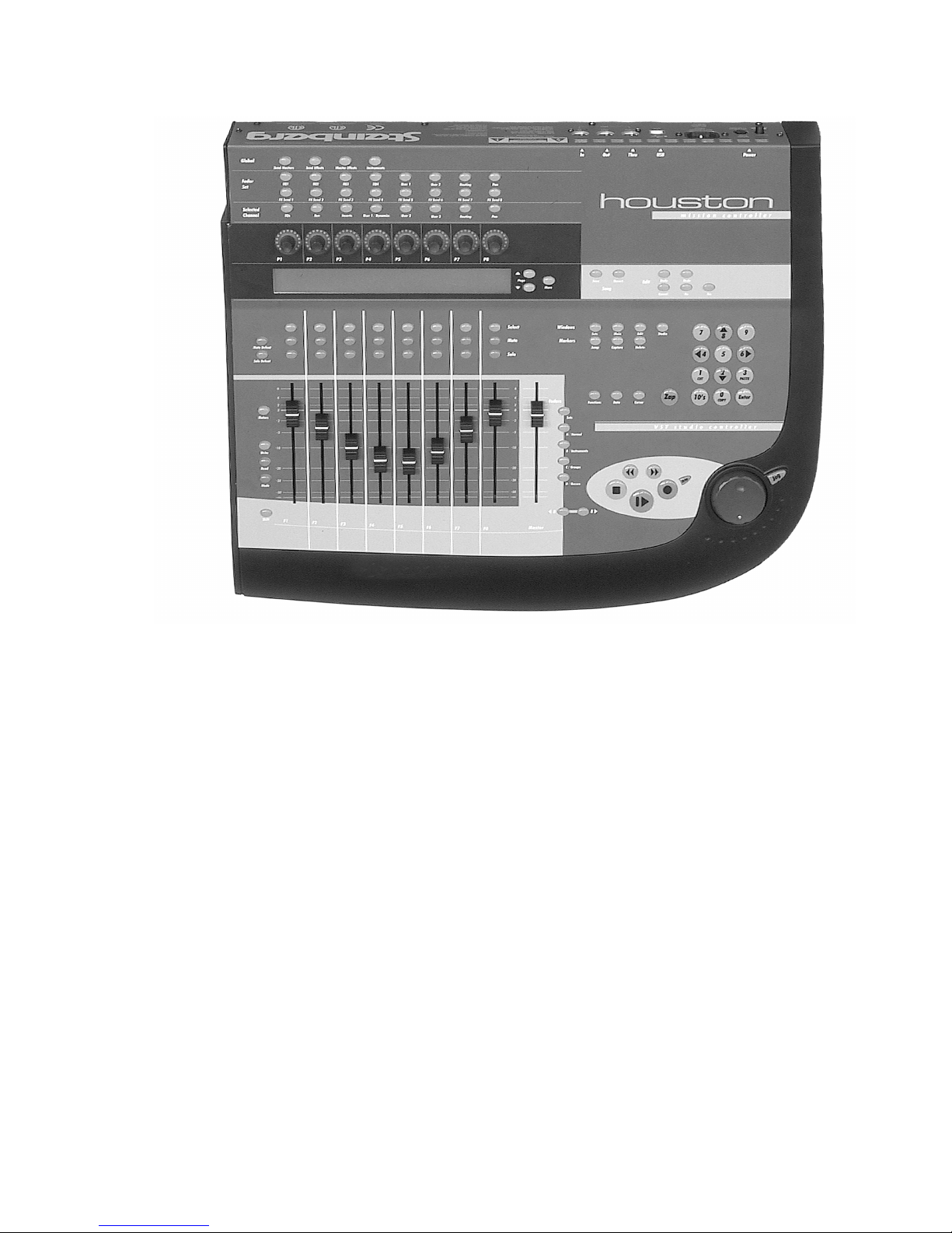
Houston’s fader section controls eight different channels in the host
application (plus the master level, which has its own fader). You select
which eight channels to control with the buttons directly to the right of
the Master fader.
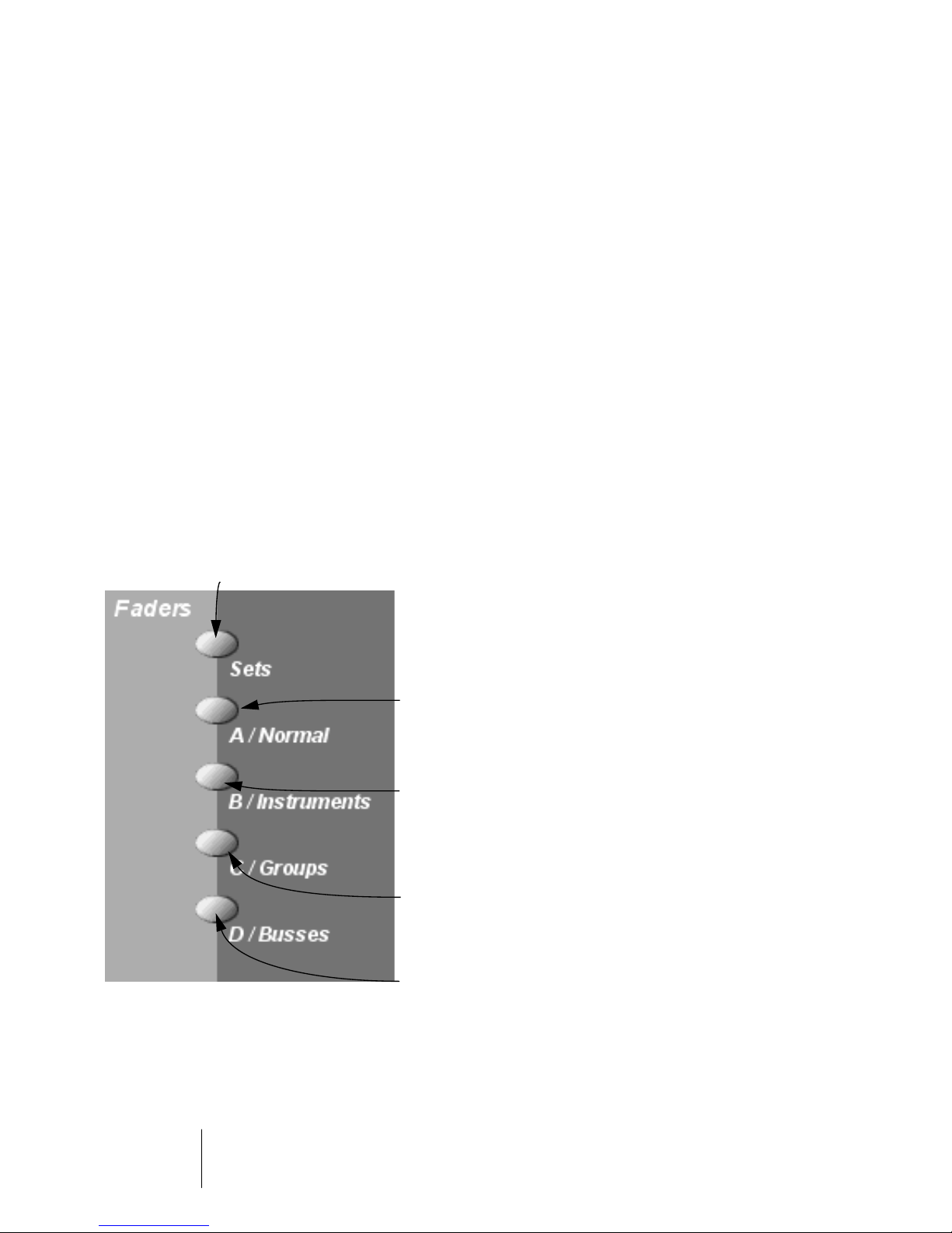
Press this to select a pre-defined “fader set” in the host application. In Cubase VST, this is a
Mixer View, as set up with the View pop-up menu in the VST Channel Mixer. This allows you to
control a combination of different channel types with the faders. After pressing the Sets button,
you enter the number of the desired set with the Number Pad (use the 10’s button for two-digit
numbers). The set/Mixer View is selected in the host application, and the faders are assigned to
control the first eight channels of the set.
Press this to assign the faders to control the first
eight regular audio channels in the host application.
Press this to assign the faders to control the first
eight ReWire channels or VST Instrument channels
(depending on the installed ReWire devices and
activated VST Instruments).
Press this to assign the faders to control the first
eight Group channels in the host application.
Press this to assign the faders to control the first
eight Output Bus channels.
Houston
1 – 6 Basic Mixing
Page 7
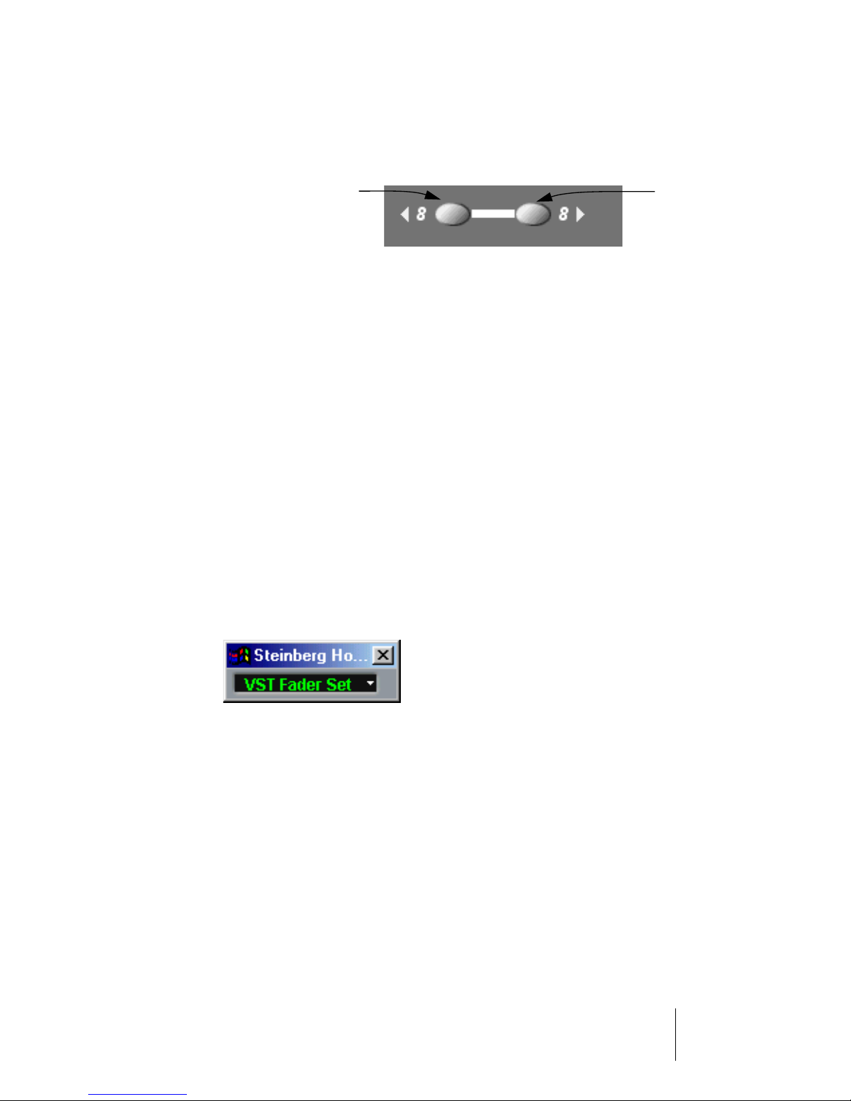
After pressing one of the buttons above, the faders are assigned to
the first eight channels of the selected set or channel type. To switch
to the next eight channels, press the 8 button.
Selects the previous
eight channels.
For example, if the faders currently control audio channels 1-8, pressing the 8 button will assign them to audio channels 9-16. To go
back to the previous eight channels, press the 8 button.
•
If you hold down Shift and press the 8 buttons, the fader assignment will shift in steps of one channel instead.
Let’s say the faders currently control audio channels 9-16. If you hold Shift and press
8, the faders will shift one step to the left and control audio channels 8-15.
Controlling the MIDI Track Mixer in Cubase VST
Houston can also be used for mixing MIDI Tracks, i.e. remote controlling the MIDI Track Mixer. However, this mode is entered from with the
program:
1.
Locate the Houston Remote Status window in Cubase VST.
This is the small floating window that appeared when you first selected Houston as
your remote device.
Selects the next
eight channels.
2.
Pull down the pop-up menu and select the “CTM” option.
Houston will now control the faders (level), pan, mute and solo in the MIDI Track Mixer.
•
You use the 8 buttons to switch between sets of eight MIDI
Tracks to control, in the usual manner.
3.
To go back to another mode (e.g. Sets or audio channels), either use
the pop-up menu in the Houston Remote Status window or use the
buttons next to the Master fader as usual.
Houston
Basic Mixing 1 – 7
Page 8

Using the Faders
Houston’s faders are used for hands-on level control and mixing, and
allow precise adjustments of the corresponding channel levels in the
host application. Since the faders are motorized, they will move to reflect any level automation you have created in your Songs. The faders
will also move when you select a new set of eight channels to control,
instantly jumping to reflect the current levels of the eight channels.
•
The faders are also touch sensitive, which means that as soon as you
move a fader manually, the motors are “overridden”.
In other words, if you have automated level changes, you can grab a fader at any time,
overriding the automation - just as you can click and hold a moving fader on screen
with the mouse.
•
Even though Houston’s motorized faders are very quiet, there may be
situations when you want absolute silence - e.g. when mixing an extremely soft and subtle piece of music. If that is the case, you can disable the motors by clicking the Motors button to the left of the faders.
When you are finished, click the Motors button again so that it lights up. The fader motors are enabled again, and the faders will instantly move to reflect the current levels.
❐
Turning the motors off does not affect the automation in the host application - all automation data is played back as usual in your Song.
Houston
1 – 8 Basic Mixing
Page 9

Mute and Solo
The two rows of buttons directly above the faders allow you to Mute
or Solo channels. The following rules apply:
•
You can Mute or Solo several channels at the same time.
•
As soon as one or more channels are Soloed, the Solo Defeat button
will light up.
Pressing this button will turn off Solo for all Soloed channels.
•
As soon as one or more channels are Muted, the Mute Defeat button
will light up.
Pressing this button will Un-Mute all Muted channels (provided that no channel is
Soloed).
•
The Mute and Solo buttons always show the status of the current set
of eight channels!
This means that if you Mute a channel and then select another set of eight channels for
fader control, the Mute indicator will go dark. However, the Mute Defeat button will still
be lit, indicating that one or more channels are Muted.
Houston
Basic Mixing 1 – 9
Page 10
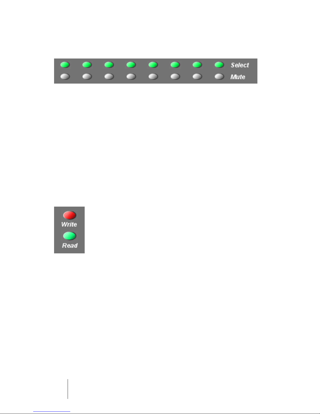
Using the Select buttons
The top row of buttons above the faders are the Select buttons. These
are used for selecting a single channel for detailed settings (Selected
Channel mode - see page 13).
•
Only one channel at a time can be selected.
•
When you Solo a channel, it is automatically selected as well.
•
If you select a channel and then select another set of eight channels
for fader control, the Select button will go dark.
This is because the channel is still selected, but it’s not shown in the current fader set.
A note about automation
The Write and Read buttons to the left of the faders control the status
of the Write and Read buttons in the host application’s mixer, allowing
remote control of mixer automation. The Automation Mode button below is reserved for future use.
Houston
1 – 10 Basic Mixing
Page 11

2
Using the Function Matrix and
Control Strip
Page 12
About this Chapter
This chapter describes how to use the Function Matrix and Control Strip
to access all VST settings in the host application; EQ, effect sends, effect and VST Instrument parameters and so on. It also contains descriptions of the available parameter pages, as shown in Houston’s display.
Basic Procedures
Selecting a Parameter Group in the Function Matrix
To be able to view the settings of a parameter in the display and edit
the values with the dials, you need to select the corresponding parameter group. This is done by pressing one of the buttons in the Function
Matrix.
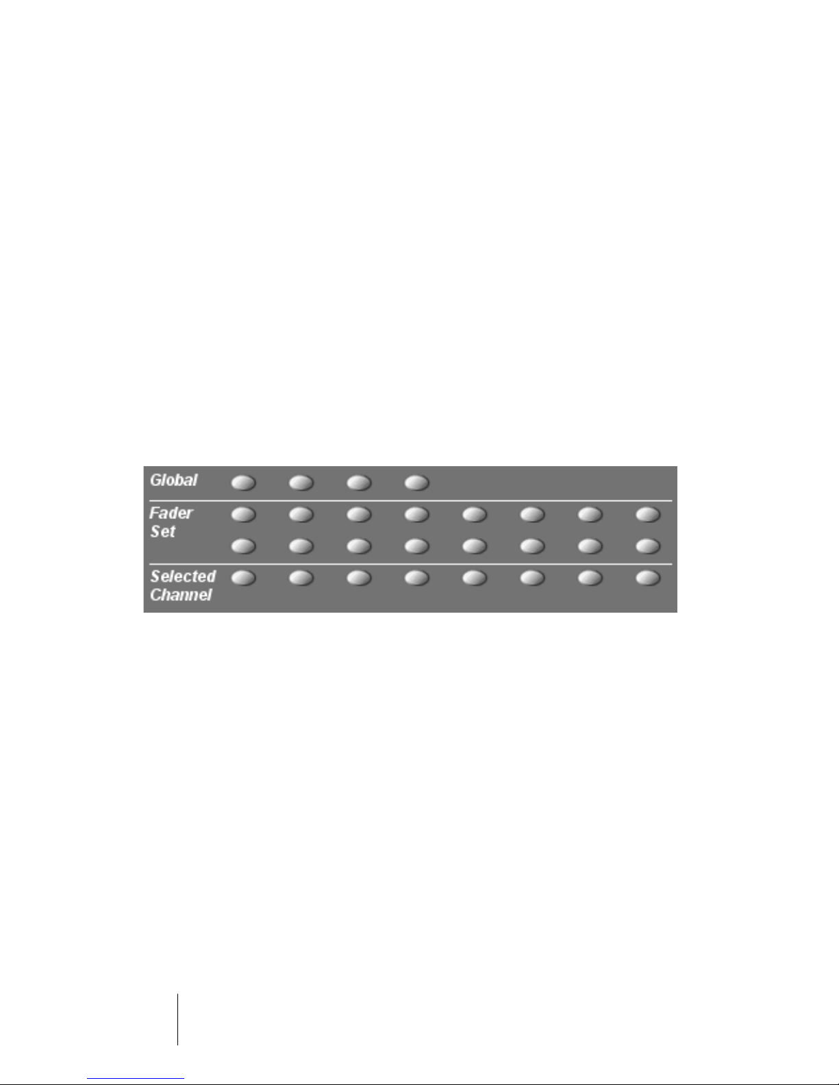
About the three modes
Houston operates in one of three modes: Selected Channel, Fader
Set or Global. Which mode is used depends on which parameter
group is selected in the Function Matrix, as indicated to the left of the
Function Matrix buttons. For example, clicking the FX Send 1 button in
the Function Matrix puts Houston in Fader set mode.
The functionality of the three modes is described on the following
pages.
Houston
2 – 12 Using the Function Matrix and Control Strip
Page 13
Selected Channel mode
This mode gives you access to up to eight different parameters at the
same time, for a single, selected channel. You can think of this as
working with a single, vertical channel strip on a mixer desk, having access to pan, EQ, sends, etc. for a single channel.
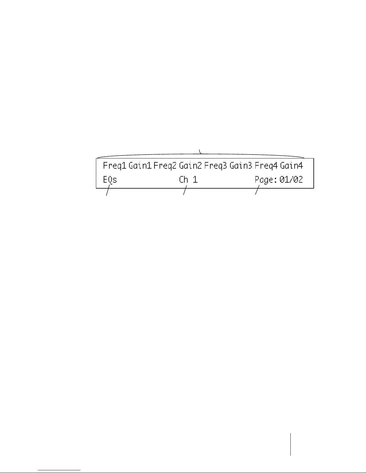
When you have selected a parameter group in this mode, the display
shows the following information:
The upper row shows the names of the available parameters. Each parameter can
be controlled with the corresponding dial. In this example, the dial P1 would control
the “Freq1” parameter, P2 would control “Gain1” and so on.
The name of the selected
parameter group.
•
You select which channel to edit in Selected Channel mode by press-
The selected
channel.
This indicates which page is shown,
and how many pages there are in
the selected parameter group. In this
example, the display shows page 1
out of 2 pages.
ing one of the eight Select buttons below the display.
See page 10.
Houston
Using the Function Matrix and Control Strip 2 – 13
Page 14
Fader Set mode
In this mode, you can view and edit a single parameter for eight different channels (the current Fader Set). You can think of this as working
with a horizontal segment of a mixer desk, e.g. the pan controls for
eight consecutive channels.
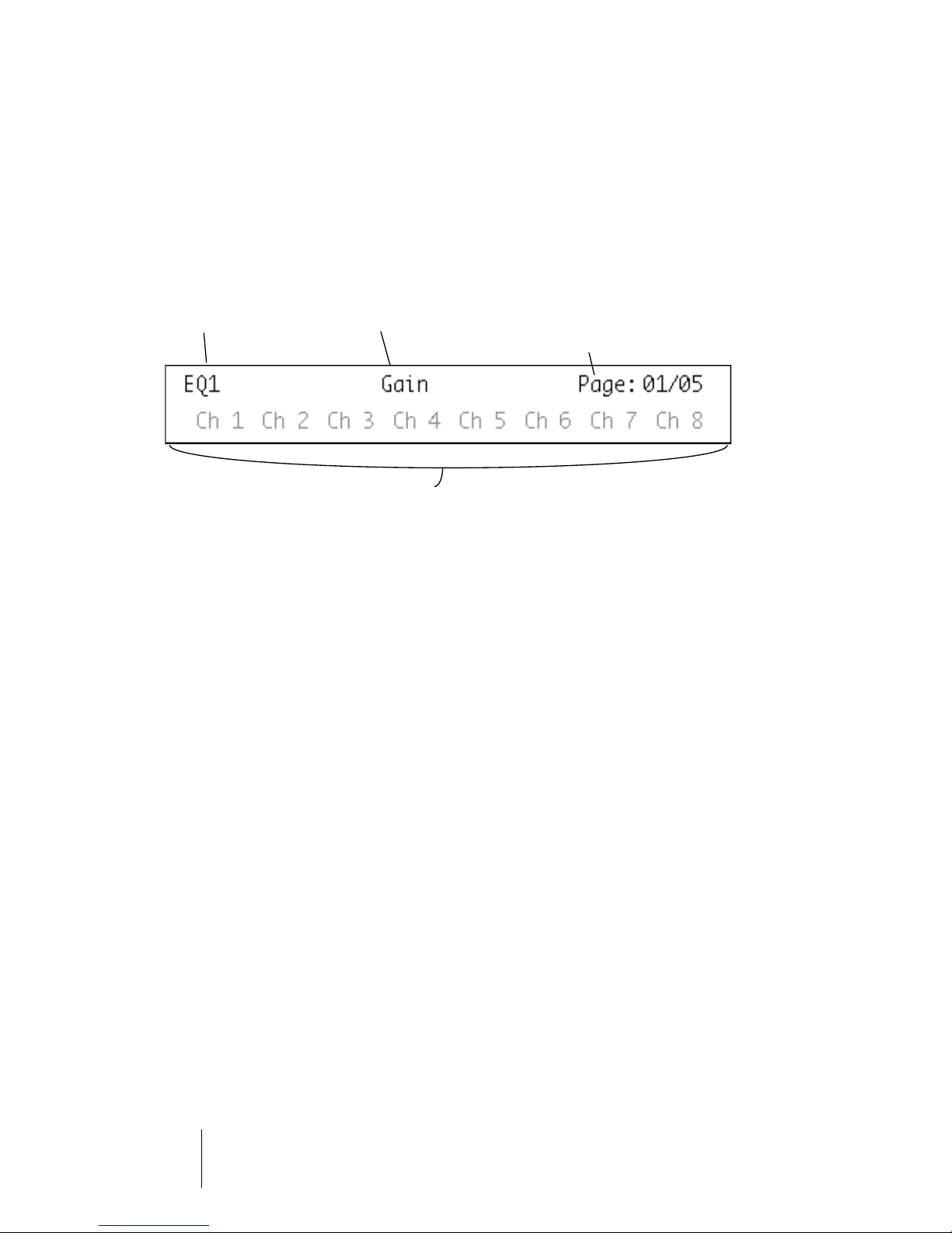
The name of the
selected parameter
group.
The lower row shows the names of the eight channels in the current Fader Set. You can
control the selected parameter for each one of the eight channels by using the corresponding dial. In this example, the dial P1 would control the EQ1 Gain parameter for the
channel “Ch1”, P2 would control the same parameter for the channel “Ch2” and so on.
•
You select which set of eight channels to edit by using the buttons to
The parameter
available for
editing.
This indicates which page is shown, and
how many pages there are in the selected
parameter group. In this example, the display
shows page 1 out of 5 pages.
the right of the Master fader, as described on page 6.
Global mode
This is where you make global settings, i.e. settings that are not related to the individual channels. Examples include parameter settings
for the Send Effects, Master Effects and VST Instruments.
Houston
2 – 14 Using the Function Matrix and Control Strip
Page 15
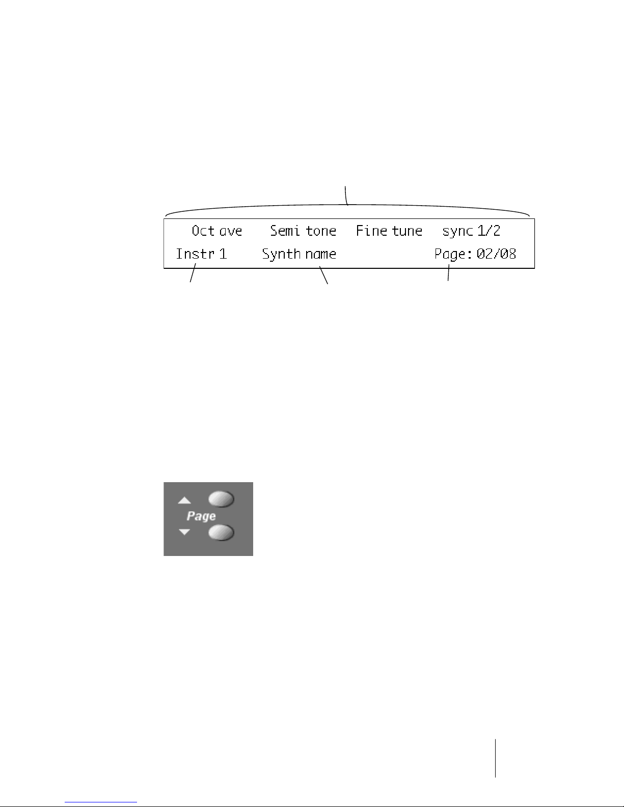
The contents of the display depend on which parameter group is selected. In this example, the “Instruments” group is selected, and the
display shows settings for one of the active VST Instruments:
The upper row shows the names of the available parameters. As you can see, there are
only four parameters shown, allowing longer parameter name. Each parameter can be
controlled with any of the two dials above it. In this example, the “Octave” parameter
would be controlled with the P1 or P2 dial, “Semitone” would be controlled with P3 or
P4 and so on.
The name of the selected parameter sub-group. See
page 16 for an explanation of
parameter sub-groups.
The name of the
VST Instrument.
This indicates which page is shown,
and how many pages there are in
the selected parameter group. In
this example, the display shows
page 2 out of 8 pages.
Using the Control Strip
When you have selected a parameter group (or parameter sub-group
– see below), you need to go to the page containing the desired parameter. This is done by pressing the Page up/down buttons next to
the display.
• Holding down the Shift button and pressing Page Up or Page Down
takes you to the first or last available page.
Once the parameter is shown in the display, you adjust its value by
moving the corresponding dial.
• When you move the dial, the display will switch to show the parameter
values instead of the parameter names.
After you have moved a dial, the display will keep the values shown for a short while
before switching back to parameter names.
Houston
Using the Function Matrix and Control Strip 2 – 15
Page 16

• To view the parameter values without making any changes, click the
More button (to the right of the Page buttons).
This makes the display switch to showing parameter values. Click the More button
again to go back to parameter names.
• The parameter values are also indicated by the LED rings around the
dials.
About Parameter Sub-Groups
Most of the settings are structured in the following way: A parameter
group (accessed by pressing a button in the Function Matrix) contains
one or several pages, each holding one or several parameters.
However, in the case of Send Effects, Master Effects, Instruments (Global mode), Inserts and Dynamics (Selected Channel mode), there is
one more hierarchical level, called a parameter sub-group. For example,
the parameters for Master Effects are structured in the following way:
The “Master Effects” parameter group contains four sub-groups - one
for each Master Effect slot in the program. Each sub-group contains a
number of pages which contain a number of parameters (both numbers
depending on the activated effects).
• To select another parameter sub-group, go to the first page of the cur-
rent sub-group and use the P1 dial.
The figure below shows the first page of the first parameter sub-group in the Master
Effects group.
This indicates Master Effect slot 1. Use the P1 dial to select another
parameter sub-group (i.e. another Master Effect slot).
Houston
2 – 16 Using the Function Matrix and Control Strip
Page 17

About the Symbols used in this chapter
On the following pages, all the different parameter groups are described. As on the Houston panel, the parameter groups are divided
into the three modes, Selected Channel, Fader Set and Global.
For quick navigation, an icon at the top of each page shows in which
mode it belongs:
This icon indicates the
“vertical” Selected
Channel mode.
This icon indicates
the “horizontal”
Fader Set mode.
This icon
indicates
Global mode.
When a group of parameters has more than one page of parameters,
this is indicated by the following symbol:
This corresponds to the Page up/down buttons next to the Houston
display.
For example, in the picture below, you would use the Page up/down
buttons to go between the “Level” and the “Enable” parameter pages:
Houston
Using the Function Matrix and Control Strip 2 – 17
Page 18

Selected Channel : EQs
Accessing the EQ controls for the current selected channel is achieved
by pressing the EQs button in the Selected Channel section of the
Function Matrix.
Please select a channel by pressing one of the Select buttons above
the faders.
The controls for the equalizers are divided into 2 pages:
Page 1 • Frequency and Gain pairs for the four bands.
Page 2 • Enable and Q controls for the four bands.
Houston
2 – 18 Using the Function Matrix and Control Strip
Page 19

Selected Channel : Aux
Accessing the Auxiliary (FX) Send controls for the current selected
channel is done by pressing the Aux button in the Selected Channel
section of the Function Matrix.
Please select a channel by pressing one of the Select buttons above
the faders.
The controls for the sends are divided into 4 pages:
Page 1 • Send Levels for each of the 8 Aux Sends.
Page 2 • Enable switches for each of the 8 Aux Sends.
Page 3 • Switches to change between pre/post fader mode.
Page 4 • Controls to choose the destination of the aux send
signal.
Houston
Using the Function Matrix and Control Strip 2 – 19
Page 20

❐
The Bus destinations control whether the aux send signal is sent directly
to the internal effects, to the Group channels or to a physical bus output
(if your sound card has additional outputs.)
Houston
2 – 20 Using the Function Matrix and Control Strip
Page 21

Selected Channel : Inserts
Accessing the Insert Effect controls for the current selected channel
is done by pressing the Inserts button in the Selected Channel section of the Function Matrix.
Please select a channel by pressing one of the Select buttons above
the faders.
• When Page 01 is selected, the Dial P1 selects which of the insert
slots is currently being edited (see page 16).
If no effect is selected for the current insert slot, the display will show
that ‘No Effect’ is selected.
After a Plug-in has been selected in the host application, the display
will change to show the selected plug-in in this effect slot and the
‘number of pages’ indicator will be updated to show the amount of
pages necessary to display all the plug-in’s declared parameters.
Houston
Using the Function Matrix and Control Strip 2 – 21
Page 22

Here the Reverb32 plug-in has been selected.
Houston
2 – 22 Using the Function Matrix and Control Strip
Page 23

Selected Channel : Dynamics
Accessing the built-in Dynamics for the current selected channel is
done by pressing the Dynamics button in the Selected Channel section of the Function Matrix.
Please select a channel by pressing one of the Select buttons above
the faders.
There are five sub-sections to the Dynamics module. Each of these has
a parameter sub-group (see page 16). When Page 01 is selected, the
Dial P1 selects which of the sub-sections is currently being changed.
Auto Gate:
Auto-Level:
Houston
Using the Function Matrix and Control Strip 2 – 23
Page 24

Soft Clip:
Limiter:
Compressor:
Houston
2 – 24 Using the Function Matrix and Control Strip
Page 25

Selected Channel : Routing
Accessing the Destination and other related parameters for the current selected channel is achieved by pressing the Routing button in
the Selected Channel section of the Function Matrix.
Please select a channel by pressing one of the Select buttons above
the faders.
The Dial P1 controls the final destination of this channel. The possible
routing destinations are the Group channels, the master bus, or any
other of the physical outputs.
❐
Not all Destinations are available for each channel. Groups can only have
higher numbered groups or physical outputs as destinations. Instrument
and Rewire channels can only have the physical outputs as destinations.
The Dial P2 controls from which physical input this channel will record
from, if it is a standard audio channel.
The Dial P3 switches the input monitoring on or off.
Houston
Using the Function Matrix and Control Strip 2 – 25
Page 26

Selected Channel : Pan
Accessing the Panning Control for the current selected channel is
done by pressing the Pan button in the Selected Channel section of
the Function Matrix.
Please select a channel by pressing one of the Select buttons above
the faders.
Depending on the nature of the pan controls in your host application,
this page will have a variable number of controls.
❐
If you have a host application that has Left-Right panning as its main
method of positioning sounds in the current setup, you may find the Pan
controls in the Fader Set section more useful. This is because the Fader
Set : Pan mode allows pan control of up to 8 channels at once.
Houston
2 – 26 Using the Function Matrix and Control Strip
Page 27

Fader Set : EQs
Accessing the Equalizer controls for the current Fader Set is done by
pressing one of the EQ buttons in the Fader Set section of the Function Matrix.
The controls for each of the four equalizers are identical and each is
divided into 5 pages:
Page 1 • Gain Controls.
Page 2 • Frequency Controls.
Page 3 • Q or Resonance Controls.
Page 4 • Enable Controls.
Page 5 • Bypass Controls.
Houston
Using the Function Matrix and Control Strip 2 – 27
Page 28

Houston
2 – 28 Using the Function Matrix and Control Strip
Page 29

Fader Set : Routing
Accessing the Routing controls for the current Fader Set is achieved
by pressing the Routing button in the Fader Set section of the Function Matrix.
The controls are divided into 3 pages:
The Dials on Page1 control the final destination of the channels in this
Fader Set. The possible routing destinations are the Group channels,
the master bus, or any other of the physical outputs.
❐
Not all Destinations are available for each channel. Groups can only have
higher numbered groups or physical outputs as destinations. Instrument
and Rewire channels can only have the physical outputs as destinations.
The Dials on Page2 control from which physical input this channel will
record from, if it is a standard audio channel.
Houston
Using the Function Matrix and Control Strip 2 – 29
Page 30

The Dials on Page3 switch the input monitoring on or off, for each
channel in the current Fader Set. This is only possible for standard
audio channels.
Houston
2 – 30 Using the Function Matrix and Control Strip
Page 31

Fader Set : Pan
Accessing the Pan controls for the current Fader Set is done by pressing the Pan button in the Fader Set section of the Function Matrix.
Each dial controls the Left/Right Panning of the corresponding channel in the current Fader Set
Houston
Using the Function Matrix and Control Strip 2 – 31
Page 32

Fader Set : FX Sends
Houston can control up to eight separate FX Sends for each channel
in a Fader Set. The available settings are the same for each of the
eight FX Sends.
❐
To access the FX Sends settings for the current Fader Set, press one of
the button FX Send 1-8 in the Fader Set section of the Function Matrix.
There are five pages of settings for each FX Send:
Page 1 • Send Levels.
Page 2 • Enable switches.
Page 3 • Switches to change between pre/post fader mode.
Page 4 • Controls to choose the destination of the aux send
signal.
Page 5 • Dry (Bypass) switches for the sends (common to all
eight sends).
Houston
2 – 32 Using the Function Matrix and Control Strip
Page 33

Houston
Using the Function Matrix and Control Strip 2 – 33
Page 34

Global : Send Masters
Houston can control the 8 Send Masters controls that adjust the total
level of the mixed signal from each auxiliary send routed to an effect in
the Send Effects Rack. Push the Send Masters button in the Function Matrix to access these controls.
Houston
2 – 34 Using the Function Matrix and Control Strip
Page 35

Global : Send Effects
Houston can control the parameters of the effects that are loaded in the
Send Effects Rack. To access these effects, push the Send Effects
button in the Global Section of the Function Matrix.
• When Page 01 is selected, the Dial P1 selects which of the effect
slots is currently being edited (see page 16).
If no effect is selected for the current slot, the display will show that
‘No Effect’ is selected.
After a Plug-in has been selected in the host application, the display
will change to show the current selected plug-in this effect slot and
the ‘number of pages’ indicator will be updated to show the amount of
pages necessary to display all the plug-in’s declared parameters.
Houston
Using the Function Matrix and Control Strip 2 – 35
Page 36

Here the Reverb32 plug-in has been selected.
Houston
2 – 36 Using the Function Matrix and Control Strip
Page 37

Global : Master Effects
Houston can control the parameters of the effects that are loaded in
the Master Effects section of the main stereo output. To access these
effects, push the Master Effects button in the Global Section of the
Function Matrix.
• When Page 01 is selected, the Dial P1 selects which of the Master
Effect slots is currently being edited (see page 16).
If no effect is selected for the current Master Effect slot, the display
will show that ‘No Effect’ is selected.
After a Plug-in has been selected in the host application, the display
will change to show the current selected plug-in this effect slot and
the ‘number of pages’ indicator will be updated to show the amount of
pages necessary to display all the plug-in’s declared parameters.
Houston
Using the Function Matrix and Control Strip 2 – 37
Page 38

Here the Symphonic plug-in has been selected.
Houston
2 – 38 Using the Function Matrix and Control Strip
Page 39

Global : Instruments
Houston can control the parameters of the Instruments that are
loaded in the VST Instruments Rack. To access the these push the
Instruments button in the Global Section of the Function Matrix.
• When Page 01 is selected, the Dial P1 selects which of the VST Instru-
ment slots is currently being edited (see page 16).
If no VST Instrument is selected for the current slot, the display will
show that ‘No Effect’ is selected.
Houston
Using the Function Matrix and Control Strip 2 – 39
Page 40

After an instrument plug-in has been selected in the host application,
the display will change to show the current selected instrument in this
effect slot and the ‘number of pages’ indicator will be updated to show
the amount of pages necessary to display all the plug-in’s declared parameters.
Houston
2 – 40 Using the Function Matrix and Control Strip
Page 41

3
Transport Control
Page 42

About this Chapter
This chapter describes how to control playback, recording and positioning in the host application from Houston.
The Transport Controls
Houston’s transport controls are located in the lower right corner of
the panel. They have the following functionality:
Rewind
Stop
Play
About the Jog Wheel
The wheel is used for moving the Song position in the host application.
The Jog button is reserved for future use.
Record
Fast Forward
Arm (Record Track selection- see below)
Jog Wheel
Houston
3 – 42 Transport Control
Page 43

About the Arm button
When using Houston with Cubase VST, you can use the Arm button
to select Tracks for recording. Proceed as follows:
1. Make sure the audio channel on which you plan to record is among
the eight channels selected for fader control.
For example, if you want to record on an Audio Track set to channel 2, you could press
the button “A/Normal”, so that the faders are assigned to the first eight audio channels.
2. Hold down the Arm button and press the Select button for the desired
audio channel.
The result depends on whether Cubase VST’s Multi Recording is activated or not:
• If Multirecord is off, this will select the first Track set to that audio
channel.
Since recording is directed to the selected Track in this mode, the Track is now ready
for recording.
• If Multirecord is on, this will record enable the first Track set to that au-
dio channel.
In Cubase VST, the record symbol will appear in the R column for the Track, indicating
that it’s ready for recording.
❐
Tracks set to channel “Any” can not be selected for recording this way.
Working with Locators and Cue Points
You can use Houston to move directly to defined Cue Points in the
Song, and to define the current Song Position as a Cue Point. The most
common use for this is probably to move to Cue Point 1 and 2 – the
Left and Right Locators.
Houston
Transport Control 3 – 43
Page 44

Jumping to a Locator/Cue Point
1. In the Markers section (to the left of the Number Pad), click the Jump
button.
The button lights up, indicating “Jump mode”.
2. Click one of the buttons 1-8 on the Number Pad to go to the corre-
sponding Locator/Cue Point.
Houston remains in Jump mode until you select another mode for the Number Pad.
Capturing a position as a Locator/Cue Point
1. Navigate to the position you want to store as a Locator or Cue Point.
2. In the Markers section, click the Capture button.
The button lights up, indicating “Capture mode”.
3. Click one of the buttons 1-8 on the Number Pad, to store the current
position as a Locator/Cue Point.
4. To avoid accidentally overwriting other Cue Points, you may want to
click the Jump button to go back to Jump mode.
❐
The Marker Delete button is reserved for future use.
Using the Zap button
The function of the Zap button is to toggle between the two latest entries made on the Number Pad. When in “Jump mode”, you can use
this to go back and forth between two different Cue Point positions in
the Song:
1. Use the Jump function to go one of the Cue Point positions.
2. Use the Jump function to go to the other Cue Point positions.
3. Now you can press the Zap button to go back and forth between the
two positions.
Houston
3 – 44 Transport Control
Page 45

4
Other Functions
Page 46

About this Chapter
This chapter describes the remaining functions available on the Houston
panel.
Song Functions
The two buttons in the Song section of the panel have the following
functionality:
• Press the Save button to save the current Song.
This is the same as selecting “Save Song” from the File menu in Cubase VST.
• Hold Shift and press Save to save a backup copy of the current Song.
This is the same as selecting “Save Backup” from the File menu in Cubase VST.
• Press the Revert button to go back to the last saved version of the
current Song.
This is the same as selecting “Revert to Saved” from the File menu in Cubase VST.
Edit Functions
To the right of the Song buttons, you will find a group of Edit buttons,
with the following functionality:
• Press Undo to undo the latest operation in the host application.
• Press Redo to “undo the undo”.
The remaining buttons in this group are reserved for future use.
Houston
4 – 46 Other Functions
Page 47

Working with Windows
The buttons in the Windows section (to the left of the Number pad)
allows you to open and close windows in the host application.
• Press the Main button to bring the current Arrange window to front.
• Press the Edit button to open an editor for the current selection.
• Hold down Shift and press Edit to close the currently active window.
• Press the Studio button to open or close the VST Channel Mixer
window.
• Hold down Shift and press the Studio button to minimize or restore all
VST windows.
Selecting a Window Set
In Cubase VST, you can store different combinations of open windows
as Window Sets, for immediate recall at any time. This allows you to
quickly switch between e.g. a layout where only mixer windows are visible, a big Arrange window, a combination of Editor windows, etc. If
you have created the desired Window Sets in Cubase VST, you recall
them from Houston in the following way:
1. Press the Sets button in the Windows section.
The button lights up, indicating that the Number Pad will be used for selecting Window Sets.
2. Enter the number of the Window Set using the Number Pad.
Note:
• The Window Sets are numbered from 0 to 99.
• To enter two-digit numbers, first press the 10’s button, then the number for
the “tens” followed by the number for the units. For example, to enter the number 24, press: 10’s, 2, 4.
• You can use the Zap button to toggle between the last two selected Window
Sets.
Houston
Other Functions 4 – 47
Page 48

Functions Mode
When the Functions button is lit, you can use the Number Pad to access various functions in the host application.
As of this writing, the following functions are available:
Number Pad button Function
0 Copy
1 Cut
3 Paste
Cursor Mode
When the Cursor button is lit, you can use the Number Pad to navigate on the computer screen.
• The blue arrow buttons (2, 4, 6, 8) work like the arrow keys on the
computer keyboard.
For example, this allows you to select Tracks and Parts in the Arrangement.
• Pressing 1 in Cursor mode is the same as pressing [Alt] on the com-
puter keyboard (PC only).
This means you get access to the menus on the main menu bar. You can use the arrow
buttons to move to the desired menu item, and press Enter to make a selection.
• Pressing 7 in Cursor mode is the same as pressing [Tab] on the com-
puter keyboard.
• Pressing 0 in Cursor mode is the same as pressing the Space bar on
the computer keyboard.
Data Mode
The Data button is reserved for future use.
Houston
4 – 48 Other Functions
Page 49

Index
Page 50

A
F
Arm Button 43
Arrow (8) Buttons 7
Arrow (Cursor) Buttons 48
Arrow (Page) Buttons 15
Automation 10
Aux 19
B
Busses Button (Faders) 6
C
Capture Mode 44
Control Strip 15
Copy 48
CTM 7
Cue Points 44
Cursor Mode 48
Cut 48
Fader Set mode 14
Fader Sets 6
Faders 8
Function Matrix 12
Functions Mode 48
FX Sends
Fader Set Mode 32
Master Levels 34
Selected Channel Mode 19
G
Global mode 14
Groups Button (Faders) 6
I
Inserts 21
Instruments (Parameter Group) 39
Instruments Button (Faders) 6
D
Data Mode 48
Dials 15
Dynamics 23
E
Edit Button (Windows section) 47
Effects
Insert Effects 21
Master Effects 37
Send Effects 35
Enter Button 48
EQ
Fader Set Mode 27
Selected Channel 18
J
Jog Wheel 42
Jump Mode 44
L
Locators 44
M
Main Button (Windows section) 47
Markers 44
Master Effects 37
MIDI Track Mixer 7
Mixer Views 6
More Button 16
Motors 8
Mute 9
N
Houston
50 Index
Normal Button (Faders) 6
Page 51

P
T
Page Up/Down Buttons 15
Pan
Fader Set Mode 31
Selected Channel Mode 26
Parameter Groups 12
Parameter Sub-Groups 16
Paste 48
R
Read Button 10
Record Track Selection 43
Redo 46
Revert 46
Routing
Fader Set Mode 29
Selected Channel Mode 25
S
Save Song 46
Select Buttons
Selecting a channel for
editing 10
Selecting Tracks for
recording 43
Selected Channel mode 13
Send Effects 35
Send Masters
Sends
Master Levels 34
Sends
Fader Set Mode 32
Selected Channel Mode 19
Sets Button (Faders) 6
Sets button (Windows section) 47
Solo 9
Studio Button
(Windows section) 47
Transport Controls 42
U
Undo 46
User 1/Dynamics 23
V
VST Instruments 39
W
Wheel 42
Window Sets 47
Write Button 10
Z
Zap Button
Cue Points 44
Window Sets 47
Houston
Index 51
 Loading...