

Page 1

Operation Manual
Page 2

Matthias Klag, Michael Ruf
Cristina Bachmann, Heiko Bischoff, Christina Kaboth, Insa Mingers, Matthias Obrecht, Sabine Pfeifer,
Benjamin Schütte, Marita Sladek
This PDF provides improved access for vision-impaired users. Please note that due to the complexity and
number of images in this document, it is not possible to include text descriptions of images.
The information in this document is subject to change without notice and does not represent a commitment
on the part of Steinberg Media Technologies GmbH. The software described by this document is subject to
a License Agreement and may not be copied to other media except as specifically allowed in the License
Agreement. No part of this publication may be copied, reproduced, or otherwise transmitted or recorded, for
any purpose, without prior written permission by Steinberg Media Technologies GmbH. Registered licensees
of the product described herein may print one copy of this document for their personal use.
All product and company names are ™ or ® trademarks of their respective owners. For more information,
please visit www.steinberg.net/trademarks.
©
Steinberg Media Technologies GmbH, 2017.
All rights reserved.
Page 3

Table of Contents
5 Installation and Setup
5 Conventions
6 System Requirements
7 Downloading Program Files
7 Installing the Program
7 Activating Your License
8 Registering Your Software
8 How You Can Reach Us
8 About the Documentation
8 Setting Up
10 Introduction
10 Window Overview
12 Common Editing Methods
12 Dials and Sliders
12 Buttons
12 Value Fields
13 Using Key Commands
13 Presets
15 Global Functions and Settings
15 Plug-in Functions Section
17 Plug-in Name and Steinberg Logo
17 Toolbar
17 Performance Controls
18 Quick Controls
24 Trigger Pads
26 Options Page
32 Editing Programs
32 Program Page Parameters
36 Editing Layers
36 Voice Tab
40 Pitch Tab
40 Oscillator Tab
43 Filter Tab
46 Amplifier Tab
48 Envelopes
54 LFOs
58 Using the Keymap
58 AUX Tab
59 Expression Controls for Instrument Layers
61 Insert Effects
62 Step Modulator
64 Modulation Matrix
76 FlexPhraser
77 Loading Phrases
77 FlexPhraser Parameters
81 Recording the MIDI Output of the
FlexPhraser
81 Phrase Playback Types
82 Variations
82 User Phrases
88 Managing Your Sounds
88 About Programs, Layers, Multis, Macro
Pages, and Presets
89 Loading Programs
90 Load Dialog
90 Slot Rack
92 Managing and Loading Files
100 Automation
100 Automation Page
100 Setting Up Automation
102 MIDI Editing and Controllers
102 MIDI Page
103 MIDI Controllers
106 Mixing and Effect Handling
106 Mix Page
107 Effect Handling
109 Included Instruments
109 Auron
117 Trium
125 Voltage
131 Model C
137 HALiotron
139 B-Box
145 World Instruments
149 World Percussion
153 Anima
171 Skylab
185 Raven
186 Eagle
188 Hot Brass
199 Studio Strings
210 Effects Reference
210 Reverb Effects
214 Delay Effects
215 EQ Effects
3
Page 4

Table of Contents
217 Filter Effects
225 Distortion Effects
229 Pitch Shift Effects
230 Modulation Effects
241 Dynamics Effects
251 Spatial and Panner Effects
252 Legacy Effects
264 Note Expression
264 Note Expression Editor
266 Library Manager
266 Library Manager Editor
269 Using the Standalone Version of the Plug-In
269 Making Preferences Settings
269 Preferences Dialog
271 Selecting the MIDI Input and the Audio
Output
271 Scratch Pad
273 Loading a MIDI File
274 Saving a MIDI File
274 Master Volume
275 Index
4
Page 5

Conventions
In our documentation, we use typographical and markup elements to structure information.
Typographical Elements
The following typographical elements mark the following purposes.
PREREQUISITE
Requires you to complete an action or to fulfill a condition before starting a
procedure.
Installation and Setup
PROCEDURE
Lists the steps that you must take to achieve a specific result.
IMPORTANT
Informs you about issues that might affect the system, the connected hardware,
or that might bring a risk of data loss.
NOTE
Informs you about issues that you should consider.
EXAMPLE
Provides you with an example.
RESULT
Shows the result of the procedure.
AFTER COMPLETING THIS TASK
Informs you about actions or tasks that you can undertake after completing the
procedure.
RELATED LINKS
Lists related topics that you can find in this documentation.
5
Page 6

Installation and Setup
System Requirements
Markup
Bold text indicates the name of a menu, option, function, dialog, window, etc.
EXAMPLE
In the header of the plug-in panel, click the Preset Management button next to the preset
name field and select Load Preset.
If bold text is separated by a greater-than symbol, this indicates a sequence of different
menus to open.
EXAMPLE
To save a specific layer, right-click it and select Load/Save> Save Layer As.
Key Commands
Many of the default key commands, also known as keyboard shortcuts, use modifier keys,
some of which are different depending on the operating system.
For example, the default key command for Undo is Ctrl-Z on Windows and Cmd-Z on Mac OS.
When key commands with modifier keys are described in this manual, they are shown with
the Windows modifier key first, in the following way:
•
Windows modifier key/Mac OS modifier key-key
EXAMPLE
Ctrl/Cmd-Z means: press Ctrl on Windows or Cmd on Mac OS, then press Z.
System Requirements
Your computer must meet the following minimum requirements:
Mac
•
Mac OS X Version 10.11/macOS 10.12
•
VST 3, AAX, or AU compatible host application for using HALion Sonic as a
plug-in
•
64-bit Intel or AMD mutli-core processor (Intel i5 or faster recommended)
•
4 GB RAM (8 GB recommended)
•
40 GB of free hard-disk space
•
Display resolution of 1366 x 768 pixels (1920 x 1080 recommended)
•
OS-compatible audio hardware*
•
Internet connection required for activation, account setup, and personal/
product registration
•
Downloads are required for the installation
*ASIO-compatible audio hardware recommended for low-latency performance
6
Page 7

Installation and Setup
Downloading Program Files
Windows
•
•
•
•
•
•
•
•
•
*Windows 7 Service Pack 1, Microsoft.NET Framework 4.0 and Platform Update
for Windows
**ASIO-compatible audio hardware recommended for low-latency performance
64-bit Windows 7*/8.x/10
VST 2, VST 3, or AAX compatible host application for using HALion Sonic as
a plug-in
64-bit Intel or AMD mutli-core processor (Intel i5 or faster recommended)
4 GB RAM (8 GB recommended)
40 GB of free hard-disk space
Display resolution of 1366 x 768 pixels (1920 x 1080 recommended)
OS-compatible audio hardware**
Internet connection required for activation, account setup, and personal/
product registration
Downloads are required for the installation
Downloading Program Files
The Steinberg Download Assistant helps you download the required files to your computer.
1.
Start the Steinberg Download Assistant.
2.
On the left, select the program that you want to install.
3.
On the right, select which version you want to install.
You can install a new program, update an existing program, etc.
4.
Click Download to download the files.
Installing the Program
After downloading the required files, you can install HALion Sonic on your computer.
On Windows systems, double-click the product installer and follow the instructions
•
on screen.
•
On a Mac, double-click the file HALion Sonic.pkg and follow the instructions on
screen.
Activating Your License
HALion Sonic uses a software-based copy protection scheme. This Soft-eLicenser is
installed automatically with HALion Sonic. It can be accessed via the eLicenser Control
Center application that is installed automatically with the product.
After installation, you must activate your product.
If you purchased HALion Sonic in a shop, the product package contains a “Download Access
Code” that allows you to download both the software and the license of the product.
If you purchased the download version of HALion Sonic, you receive an e-mail with the
activation code and a description of the activation process.
7
Page 8

Installation and Setup
Registering Your Software
IMPORTANT
The process for license activation is described in detail on the Steinberg web site.
Registering Your Software
Register your product at the MySteinberg online customer portal. As a registered user,
you are entitled to technical support, you gain access to exclusive offers such as software
updates and upgrades, and more.
PROCEDURE
1. Start your software.
2. Select Help> Register now.
An online registration form opens in your web browser.
3. Follow the instructions on screen to register at MySteinberg.
How You Can Reach Us
Click the Steinberg logo in the top right corner of the control panel to open a pop-up menu
containing items for getting additional information and help.
•
This menu contains links to various Steinberg web pages. Select a link to open
the corresponding page. On the web pages, you can find support and compatibility
information, answers to frequently asked questions, links for downloading new drivers,
etc.
•
You also find a menu item for the registration of your product.
As a registered user, you are entitled to technical support, you gain access to exclusive
offers such as software updates and upgrades, and more.
About the Documentation
The documentation is available online and most of it can be downloaded in PDF format from
steinberg.help.
•
To visit steinberg.help, enter steinberg.help in the address bar of your web
browser or open HALion Sonic, click the Steinberg logo in the top right corner and
select Help> HALion Sonic Help.
Setting Up
The following sections describe how to use HALion Sonic as a plug-in in different host
applications.
NOTE
HALion Sonic can also be used as a standalone application.
8
Page 9

Installation and Setup
Setting Up
Selecting Outputs
HALion Sonic loads with a stereo output configuration by default. However, you can use up to
15 additional outputs in the Steinberg DAW. This allows you to route all 16 program slots to a
dedicated channel in the MixConsole.
PROCEDURE
1. To make the outputs available in the VST instrument, open the VST Instruments
window.
2. Click the Activate Outputs button for the instrument.
3. Activate the outputs that you want to use.
RESULT
The Steinberg DAW automatically adds an output channel for each additional output to
the MixConsole. You can now route programs or layers to these outputs for further signal
processing within the DAW.
Using the Instrument in an AU-Compatible Application
The AU version of HALion Sonic is installed in your AU plug-ins folder and lets HALion Sonic
work in an AU environment without any performance loss or incompatibilities.
For example, to load HALion Sonic as an AU instrument for Logic Pro, proceed as follows:
PROCEDURE
1. Open the Track Mixer and select the instrument channel that you want to use.
2. Click in the I/O field and select AU Instruments> Steinberg> HALion Sonic.
3. Select one of the available channel configurations.
Using the Instrument as Standalone Application
HALion Sonic can be used as a standalone application, independently of any host application.
In this case, you can connect the instrument directly to your audio hardware.
RELATED LINKS
Using the Standalone Version of the Plug-In on page 269
9
Page 10
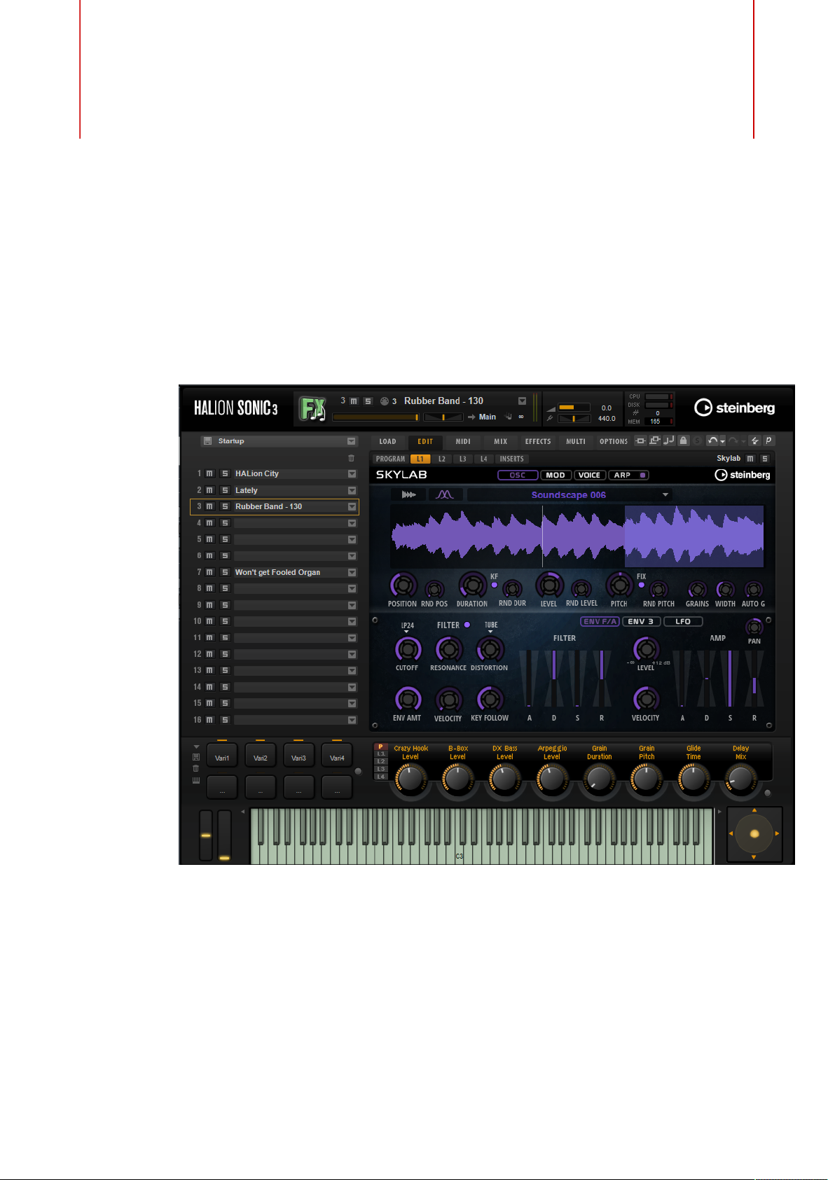
Window Overview
The application interface follows a fixed-size single window concept.
Introduction
The window is subdivided into several sections:
• The plug-in functions section at the top of the application window.
• The multi program rack on the left.
• The toolbars above the edit display.
• The edit display on the right. It contains the Load, Edit, MIDI, Mix, Effects, Multi, and
Options pages.
• The performance section at the bottom. It contains the trigger pads, the quick controls,
the performance controllers, and the sphere control.
10
Page 11

Introduction
Window Overview
• If you are using the standalone version of HALion Sonic, you find a number of specific
View Options
You have two view options: the full-size editor view and the smaller player view. In the player
view, only the plug-in functions, the trigger pads, the quick controls, and the performance
controllers are visible.
• Click the p button in the toolbar above the edit display to switch between the views.
functions in an extra section at the top of the application window.
When the player view is active, the button changes to e, indicating that clicking again
lets you return to the editor view.
11
Page 12

Common Editing Methods
Dials and Sliders
Dials and sliders can be unidirectional or bidirectional. Unidirectional values, for example
level values, start at a minimum value and go up to the maximum. Bidirectional controls
start from the middle position and go to the left for negative and to the right for positive
values.
Most of the editing methods are the same for dials and sliders.
• To adjust a value, click a dial or a fader and drag up and down, or use the mouse
wheel.
If you press Alt when clicking a dial, a small fader appears, allowing you to set the
parameter.
• To make fine adjustments, press Shift and move the dial or use the mouse wheel.
• To restore the default value for a parameter, press Ctrl/Cmd and click on the control.
Buttons
On/Off Buttons
These buttons have two states: on and off. If you move the mouse over an On/Off button, it
changes its appearance to show that you can click it.
Push Buttons
Push buttons trigger an action and then go back to their inactive state. These buttons open
menus or file dialogs.
Value Fields
To set a value, you have the following possibilities:
• Double-click in a value field, enter a new value, and press Enter.
• Click in the value field and drag up or down.
• Position the mouse over a value field and use the mouse wheel.
• Click the up/down triangles next to the field.
If the entered value exceeds the parameter range, it is automatically set to the
maximum or the minimum value, respectively.
12
Page 13

Common Editing Methods
Using Key Commands
• To set the parameter to its default value, Ctrl/Cmd-click the value field.
• To use a fader to adjust the value, Alt-click a value field.
• To enter musical values, such as key ranges or the root key, with your MIDI keyboard,
double-click the value field, press a key on your MIDI keyboard, and press Return.
• To navigate to the next parameter, press Tab. To jump backwards to the previous
parameter, press Shift-Tab.
If no parameter is selected inside the focused view, pressing Tab always jumps to the
first parameter.
Using Key Commands
The commands are arranged in a hierarchical folder structure on the left. When you open
a category folder, the items and functions are displayed with any currently assigned key
commands.
• To set up a key command, select the function in the list, enter the key command in
the Type in Key field and click the Assign button to the right of the field. If this key
command is already used for another function, this is displayed in the field below.
Presets
• To delete a key command, select the function in the list, select the key command in the
Keys list and click the Delete button.
• To search for a specific function, enter its name in the search field at the top of the
dialog and click the search button.
NOTE
You can set up several key commands for the same function.
HALion Sonic offers two types of presets: section/module presets and VST presets. Section
and module presets store and recall the setup of a specific component on the HALion Sonic
panel. VST presets contain all information necessary to restore the complete state of the
plug-in.
During setup, the factory presets are installed in a dedicated folder and a user folder is
created for your own presets. The handling of presets is the same throughout the program.
NOTE
Factory presets are write-protected, but may be overwritten when a software update is
executed. Presets in your user folder are never changed by the software update.
For more information on VST presets, see the Operation Manual of your Steinberg DAW.
Handling Section and Module Presets
The preset controls can be found throughout the program. The handling is always the same.
• To save a preset, click Save .
13
Page 14

Common Editing Methods
Presets
NOTE
You cannot overwrite factory presets. If you want to save changes made to a factory
preset, save the preset under a new name or in a new location.
• To load a preset, click the arrow icon and select a preset from the list.
• To delete a preset, click Delete .
NOTE
Factory presets cannot be deleted.
Handling VST Presets
Loading VST Presets
PROCEDURE
1. In the header of the plug-in panel, click the Preset Management button next to the
preset name field and select Load Preset.
2. Do one of the following:
•
•
Saving VST Presets
PROCEDURE
• In the header of the plug-in panel, click the Preset Management button next to the
preset name field and select Save Preset.
Select a preset to load it.
Double-click a preset to load it and close the preset loader.
14
Page 15

Global Functions and Settings
Plug-in Functions Section
The plug-in functions section at the top of the window gives you access to global functions
that affect both the currently loaded programs, and the general working of the plug-in.
The plug-in functions section contains the multi slot section, the program slot section, the
master section, and the performance displays.
Program Slot Section
This section contains a copy of the slot that is selected in the multi program rack, as well as
the main parameters of the program.
The slot parameters are the same as in the multi program rack. In addition, the following
parameters are available:
Slot Number
The number of the active slot. You can switch to another slot by clicking the slot
number and selecting an entry from the list.
NOTE
Only slots that contain programs are available on the list.
Load Icon
Click the Load icon to the right of the slot to open the program loader. Doubleclick a program to load it.
MIDI Activity Indicator
The MIDI symbol starts blinking when incoming MIDI data is detected.
Level
Adjusts the output level of the slot.
Pan
Adjusts the position of the slot in the stereo panorama.
Output
On the output selector, you define the output destination of the slot signal.
15
Page 16

Global Functions and Settings
Plug-in Functions Section
Polyphony
Sets the number of keys that can be played simultaneously.
NOTE
One key can trigger several layers. On the performance meter, you can see how
many voices are triggered by your playing.
Program Icon
The program icon indicates the sound category to which the program belongs. It
depends on the category and subcategory tags that are specified for a program in
the MediaBay.
Master Section
The master section can be used to set volume and tuning of the plug-in.
Master Volume
Adjusts the overall volume of the plug-in.
Master Tune
You can set the Master Tune slider from 415.3 Hz to 466.2 Hz, which equals -100
cents to +100 cents.
Performance Displays
The meters and text displays indicate the system load of the plug-in.
CPU
This meter shows the processor load during playback. The more voices you play,
the higher the processor load. If the overload indicator lights up, reduce the Max
Voices setting on the Options page.
Disk
This meter shows the hard disk transfer load during the streaming of samples
or when loading presets. If the overload indicator lights up, the hard disk is not
supplying data fast enough. In such a case, open the Options page and adjust the
Disk vs. RAM slider towards RAM or decrease the Max Voices setting.
Polyphony
This display indicates the number of samples that are currently played back, to
help you trace performance problems. For example, if you have to reduce the Max
Voices setting on the Options page, you can verify your settings by monitoring the
number of samples that are currently playing.
Memory
This display indicates the overall amount of RAM that is currently used by the
plug-in and the loaded programs. The number refers to the streaming buffer and
the preloaded samples. The MEM display helps you trace performance problems.
For example, if you need to free up memory for other applications, you can adjust
16
Page 17

Global Functions and Settings
Plug-in Name and Steinberg Logo
the Disk vs. RAM slider on the Options page toward Disk. You can verify your
settings by monitoring the MEM display.
Plug-in Name and Steinberg Logo
To get information regarding the version and build number of the plug-in, click the plugin logo. This opens the About box. To close the About box, click it or press Esc on your
computer keyboard.
If you click the Steinberg logo in the top right corner of the plug-in interface, a pop-up menu
opens. Select one of the options to navigate to Steinberg web pages containing information
on software updates, troubleshooting, etc.
Toolbar
The toolbar below the plug-in functions section contains controls for loading multi-programs
on the left, the buttons to switch between the different pages, and various useful global
functions.
Global insert, AUX, and FlexPhraser buttons
Use these buttons to switch off all insert effects, AUX effects, and FlexPhrasers
for the whole plug-in at once. You can use this to compare sounds with and
without effects or to use a preset without the FlexPhrasers, for example.
Lock button
If this button is activated, loading another program or layer does not overwrite
the current FlexPhraser and trigger pad settings.
MIDI Reset
Click this button to stop playback and reset all MIDI controllers to their default
values.
Undo/Redo
To undo or redo a single operation, click the Undo or Redo buttons. To undo or
redo multiple operations, click the arrow next to the button to open the history
and select the step to which you want to return.
Editor/Player
This button toggles between the two views: the full-size editor view (e) and the
smaller player view (p).
Performance Controls
The performance controls are located in the lower part of the window.
17
Page 18
Global Functions and Settings
Quick Controls
Wheel Controls
To the left of the internal keyboard, the pitchbend wheel and the modulation wheel are
located.
The modulation wheel is hardwired to MIDI controller #1, which is normally used as a source
in the modulation matrix, but can be used as a quick control as well.
Keyboard
The virtual 88-note keyboard can be used to trigger MIDI notes. By clicking the keys at
different vertical positions you can control the note-on velocity. Furthermore, the keyboard
displays keys that are not used to trigger notes but act as key switches. The Shift Keyboard
buttons to the left and right of the keyboard shift the keyboard range by octaves. This allows
you to display key switches that are located on lower keys, for example.
Sphere Control
The sphere is a two-dimensional control. It allows you to adjust two parameters
simultaneously, by dragging the mouse horizontally (Sphere H) and vertically (Sphere V).
Typically, two parameters that belong together are assigned to the sphere, such as cutoff and
resonance.
If parameters are assigned to Sphere H and Sphere V, triangles for indicating the horizontal
and vertical axis are available.
You can reset the sphere to the center position using the corresponding options on the
context menu.
• If Center Horizontal and/or Center Vertical are activated, the sphere returns to the
corresponding center position as soon as you release the mouse button.
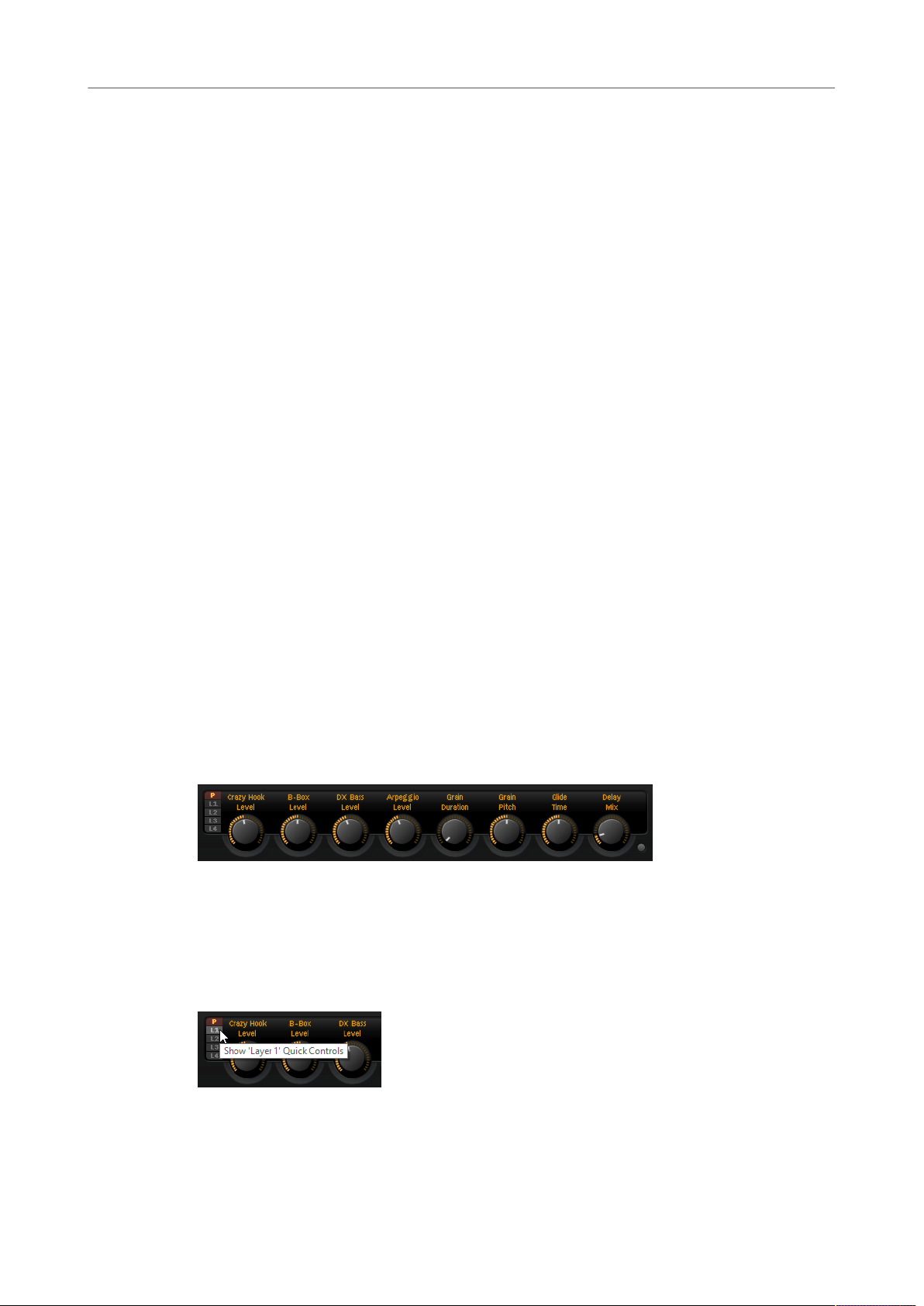
Quick Controls
Quick controls allow you to remote-control any parameter inside the program.
For each program and layer, eight quick controls are available. Furthermore, Sphere H,
Sphere V, and the modulation wheel can also serve as quick controls.
If a layer contains zones, these zones are also affected by the quick controls of the layer.
•
To switch between the quick controls of the program and the layers, use the buttons to
the left of the potentiometer controls.
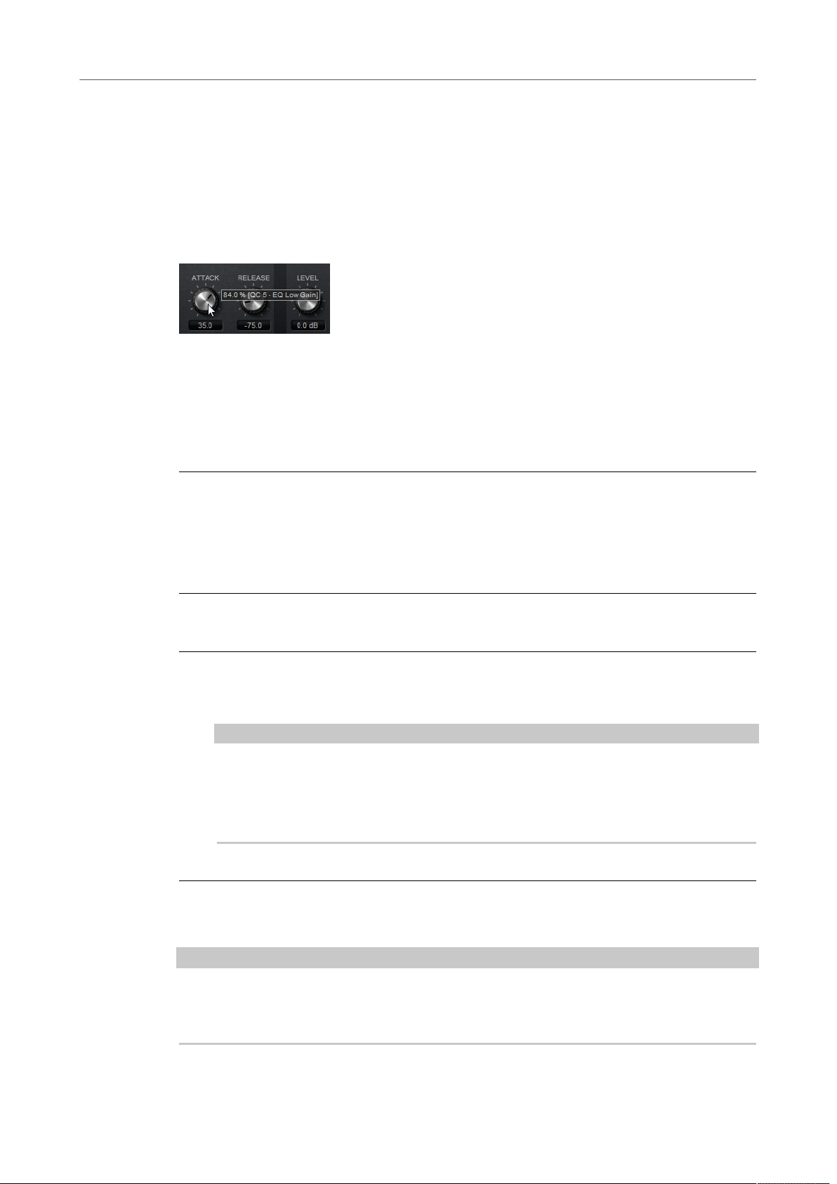
Value Tooltips
If you use quick controls, the following situations can happen:
18
Page 19
Global Functions and Settings
Quick Controls
•
The actual value of a parameter and the value that is displayed in its value field differ.
•
A button on the user interface is deactivated but the corresponding parameter is
active.
For example, this can happen if the quick control introduces an offset or if a button is
controlled by a quick control.
Therefore, parameters that are assigned to a quick control show a value tooltip. This value
tooltip indicates the resulting parameter value and the name of the assigned quick control.
Value tooltips can be activated or deactivated on the Options page.
RELATED LINKS
Global Section on page 29
Accessing Quick Controls
PROCEDURE
1. Select the program that you want to edit in the multi program rack.
2. Use the buttons to the left of the quick controls to select whether you want to access
the quick controls for the program or for one of the layers.
The quick controls change to the settings of the program or the selected layer.
Assigning Quick Controls
PROCEDURE
1. In the editor for a program, a layer, or an insert effect, right-click the control to which
you want to assign a quick control.
NOTE
•
Parameters of a layer can only be assigned to the quick controls of this layer.
•
If you want to assign the parameters of a layer to the quick controls of a
program, you must first assign the parameter to a quick control of the layer, and
then assign the quick control of the layer to a quick control of the program.
2. On the Assign Quick Control submenu, select the quick control that you want to assign.
RESULT
The assignment is created.
NOTE
You can also assign a quick control as modulation source or modulation modifier in the
modulation matrix. This allows you to combine the quick control with other modulation
sources.
19
Page 20

Global Functions and Settings
Quick Controls
RELATED LINKS
Modulation Matrix Parameters on page 67
Setting the Minimum/Maximum Range
You can set the minimum and maximum range for each assignment separately. This gives
you better control over the parameter change.
•
Right-click a control and define the range using the Set Minimum and Set Maximum
commands.
•
In the Quick Control Assignments editor, enter the values in the Minimum Value and
Maximum Value fields or click and drag the handles in the curve display.
Trimming the Range
The Trim Range function allows you to automatically set the best quick control range,
depending on the current parameter value.
PROCEDURE
• In the Quick Control Assignments editor, right-click the assignment in the list on the
right.
•
To trim the range of a single assignment, select Trim Range.
•
To trim the range of all quick controls, select Trim Range of All Quick Controls.
RESULT
The minimum and maximum values are set automatically.
NOTE
If you change the original parameter, you have to apply the Trim Range function again to
guarantee the best control range.
Setting the Default Range
PROCEDURE
• In the Quick Control Assignments editor, right-click the assignment on the right.
•
To set the default range of a single assignment, select Set Default Range.
•
To set the default range of all quick controls, select Set Default Range of All
Quick Controls.
RESULT
The quick controls are set to their maximum possible range.
NOTE
If you change the original parameter, you must apply the Set Default Range function again to
guarantee the best control range.
20
Page 21
Global Functions and Settings
Quick Controls
Unassigning Quick Controls
PROCEDURE
• Do one of the following:
•
To remove a quick control assignment, right-click the parameter in the Quick
Control Assignments editor and select Remove Assignment.
•
To remove all assignments of the selected quick control, open the context menu
and select Remove All Assignments.
•
To remove all quick control assignments for all 8 quick controls, select Remove
All Assignments of All Quick Controls.
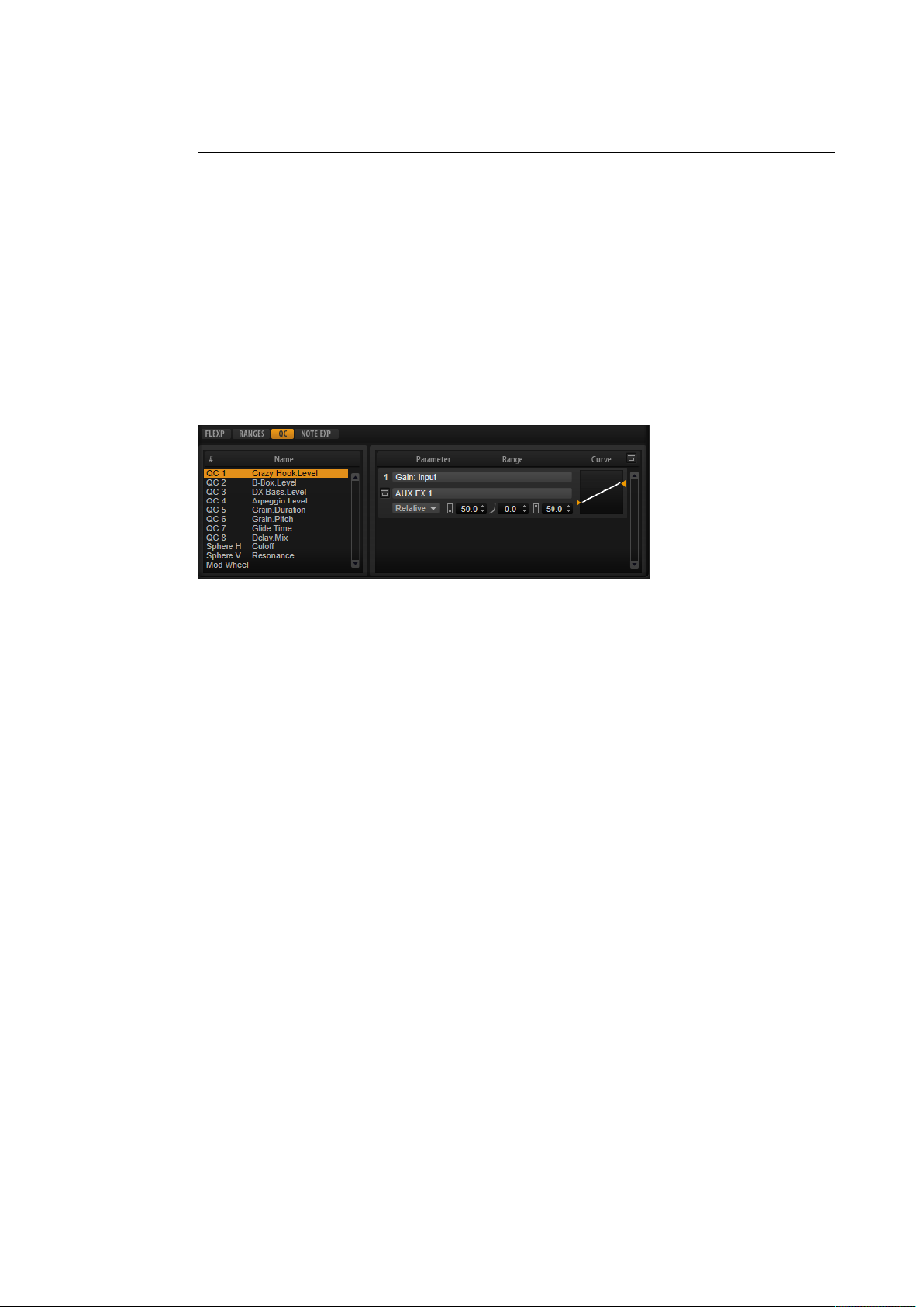
Quick Control Assignments Editor
• To open the Quick Control Assignments editor, right-click a quick control and select
Edit Quick Control or open the Edit page for a program and select the QC tab in the
lower part of the page.
Bypass All Quick Control Assignments
Allows you to hear a sound without quick control assignments.
Quick Controls List
The eight quick controls are listed on the left. The assignments of the selected
quick control are listed on the right. You can edit the parameters for each
assignment separately.
Quick Control Parameter
Displays the parameter assignment for the selected quick control.
Affected Layers/Modules
Displays which program, layer, or module is affected by the quick control.
Bypass Single Quick Control Assignment
Bypasses the corresponding quick control assignment.
For example, if a quick control is assigned to several layers, this option allows
you to bypass the quick control assignment for one of the layers only.
Mode
Determines the mode that is used for changing the parameter values.
21
Page 22

Global Functions and Settings
Quick Controls
Minimum Value
Sets the minimum value for the quick control assignment.
Curvature
Sets the curvature. You can also set the curvature by clicking and dragging in the
curve display.
Maximum Value
Sets the maximum value for the quick control assignment.
Bypass All Quick Control Assignments
Bypasses all assignments for the selected quick control.
RELATED LINKS
Setting the Mode for the Quick Control Assignment on page 23
Adjusting the Curvature on page 22
Bypassing Quick Controls on page 23
Managing Quick Controls
The Quick Control Assignments editor allows you to manage and edit assigned quick
controls.
•
To rename a quick control, click in the Name column and enter a new name.
•
To change the order of quick control assignments, drag an assignment between two
other quick controls. When a line is shown, release the mouse button to insert the
quick control assignment.
•
To replace a quick control assignment, drag it onto another quick control. When a
rectangle is shown, release the mouse button to replace the quick control assignment.
Adjusting the Curvature
You can adjust the curvature of each assignment in the Quick Controls Assignment editor
separately.
PROCEDURE
• To adjust the curvature, do one of the following:
•
Select the quick control that you want to edit and specify a value in the Curvature
value field.
Positive values change the curvature towards logarithmic behavior and negative
values towards exponential behavior.
•
Click and drag the curvature in the display on the right.
22
Page 23

Global Functions and Settings
Quick Controls
Setting the Mode for the Quick Control Assignment
A quick control behaves either as continuous control or as a switch. In addition, it remotecontrols a parameter either in relative or absolute mode. You can specify a mode for each
assignment.
You can set the behavior in the context menu for the control itself or via the pop-up menu in
the Quick Control Assignments editor.
Absolute
Remote-controls the parameter values continuously. Absolute mode changes the
assigned parameters by overwriting them with the current quick control value,
that is, parameter changes are overwritten.
Relative
Remote-controls the parameter values continuously. Relative mode changes the
values of the assigned parameters without losing their relative settings, that is,
parameter changes can still be heard.
Switch Relative
Switches between the minimum and maximum value. Parameter changes can
still be heard.
Neutral Setting
If you adjust the range of a quick control assignment, it can become necessary to change its
neutral setting, to prevent the resulting sound from changing.
If you adjust the range of a quick control that has a single assignment that uses Absolute or
Relative mode, HALion Sonic adjusts the setting of the quick control automatically so that
the sound does not change. Likewise, if you assign multiple parameters to the same quick
control, HALion Sonic sets the range of this quick control assignment automatically.
However, if a quick control has multiple assignments and you change the range of one or
more assignments, the neutral setting cannot be set automatically. In this case, you can
specify the neutral setting manually using the Set Quick Control to Neutral Setting command
on the context menu for the quick control.
Bypassing Quick Controls
Bypassing quick controls allows you to hear a sound without quick control assignments.
1. To bypass a single assignment for one quick control, click Bypass Single Quick Control
Assignment in the Quick Control Assignments editor.
2. To bypass all assignments for one quick control, select the quick control in the Quick
Control Assignments editor, and click Bypass All Quick Control Assignments in the
upper right of the parameter section.
23
Page 24
Global Functions and Settings
Trigger Pads
Assigning Quick Controls in the Modulation Matrix
In addition to assigning the quick controls directly to parameter controls, you can also assign
them as source or modifier in the modulation matrix. This way, you can combine the quick
control with other modulation sources.
PROCEDURE
1. Open the layer editor and go to the modulation matrix.
2. On the pop-up menu in the Source/Modifier column, open the Assign Quick Control
submenu and select the quick control.
The submenu lists the quick controls of the layer.
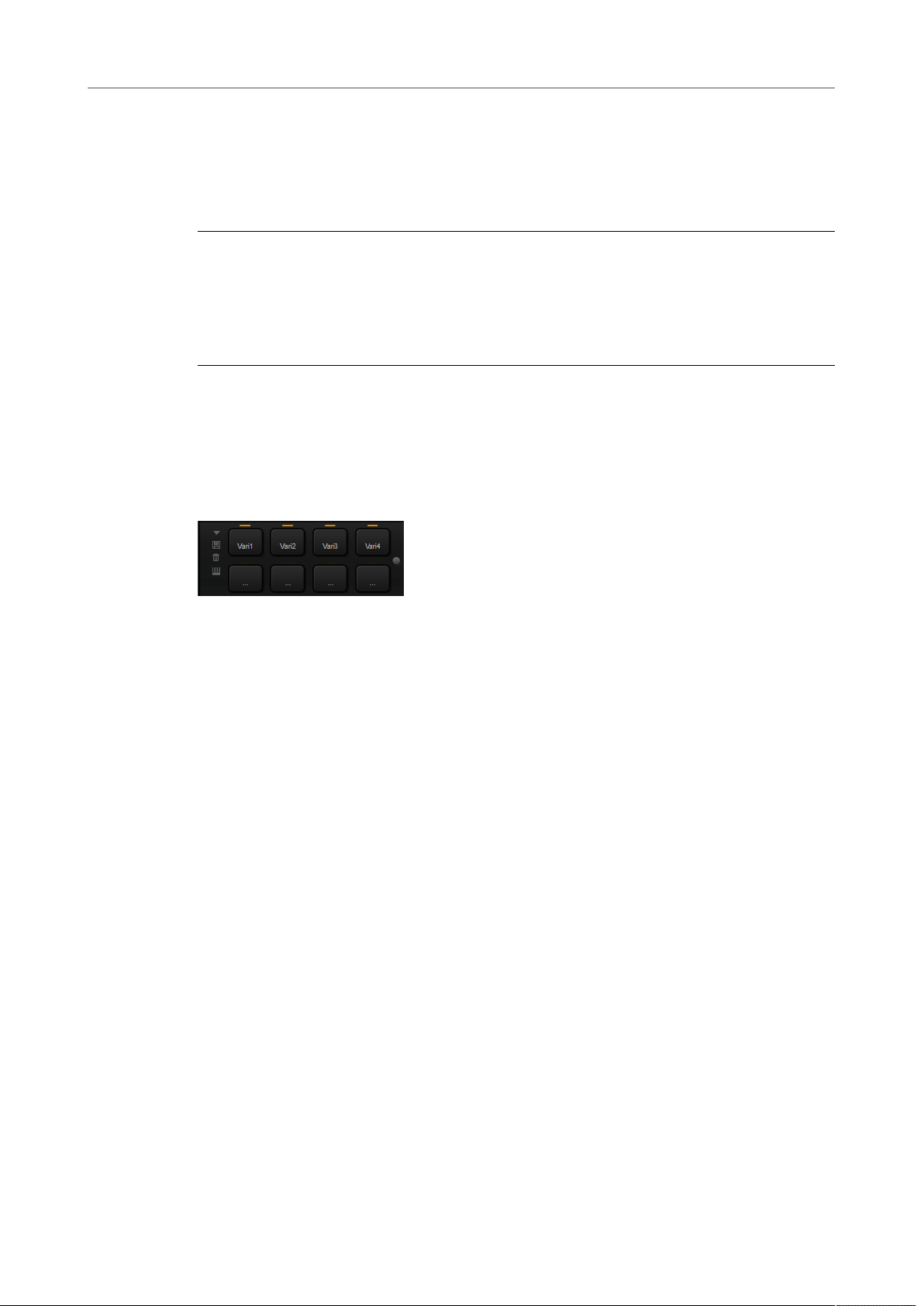
Trigger Pads
You can use the trigger pads to trigger single notes or whole chords and to switch between
FlexPhraser variations.
Many of the programs that come with HALion Sonic make use of the trigger pads.
If a note or a chord is assigned to a pad, this pad turns orange. If a pad switches between
FlexPhraser variations, the line above the pad turns orange.
•
To trigger a pad, click on it.
Presets
Pad presets save trigger notes and chord snapshots, but not FlexPhraser
snapshots. This means that you can exchange trigger notes and chords by
loading presets without loosing your FlexPhraser snapshots.
Bypass
With the Bypass Pads button to the right of the trigger pads, you can bypass the
entire pads section. This deactivates any functionality you assigned to the trigger
pads.
Assigning Trigger Notes to Pads
You can assign a MIDI note to a pad and trigger the pad by playing this note.
To define the trigger note, do one of the following:
•
Right-click a pad, open the Assign Trigger Note submenu, and from the further
submenus, select the octave and note that you want to assign.
•
Open the context menu for a pad, select Learn Trigger Note, and play the note on your
MIDI keyboard or click a key on the internal keyboard.
The name of the assigned trigger note is displayed in the top left corner of the pad.
On the internal keyboard, keys that serve as trigger notes are shown in blue. These keys do
not play sounds, but trigger the corresponding pads instead.
24
Page 25

Global Functions and Settings
Trigger Pads
•
To remove a trigger note from a pad, right-click the pad and select Forget Trigger
Note.
Assigning Chords or Notes to Trigger Pads
PROCEDURE
1. Right-click a pad and select Snapshot Chord.
The pad starts blinking.
2. Do one of the following:
•
Play a chord or a single note and then click the pad that is blinking to assign the
chord or note to the pad.
•
Drag a chord event from the chord track of your Steinberg DAW onto a trigger
pad. This transfers the corresponding MIDI notes to the pad.
If you drag a chord event onto the internal keyboard first, the corresponding
chord is played back. This is useful to verify whether you selected the correct
chord.
If you define a chord that contains a key switch, you can trigger the chord with a
specific instrument expression.
If you add keys to a chord that also work as trigger notes, they trigger the underlying
MIDI note instead of the trigger note.
RESULT
Triggering the pad now plays the chord or note.
Default Trigger Note Settings
Assigned trigger notes are saved with each program to allow for maximum flexibility.
However, you can save a fixed set of default trigger notes to reflect an existing hardware
setup, for example.
•
To specify a default set of trigger notes, set up the trigger notes for all pads, right-click
a pad, and select Save Trigger Notes as Default.
•
To activate the default trigger note settings, right-click a pad and select Use Default
Trigger Notes.
Now, changing programs or multi-programs does not change the trigger notes
anymore.
If you deactivate Use Default Trigger Notes, the last set of trigger notes remains active. To
return to the trigger notes that were saved with the program, reload the program.
Assigning Key Switches to Trigger Pads
To use the pads for switching between expressions, assign them to the corresponding key
switches.
PROCEDURE
• Right-click a pad, select Snapshot Chord, and play the key switch.
25
Page 26

Global Functions and Settings
Options Page
Removing Chords or Notes from Trigger Pads
PROCEDURE
• Right-click the trigger pad and select Clear Chord.
Switching between Variations
You can switch between variations using the trigger pads.
Variations are available for the FlexPhraser and the B-Box, for example.
PROCEDURE
1. Right-click the trigger pad that you want to use for switching to the selected
FlexPhraser variations.
2. On the menu, select Snapshot Variation.
The line above the pad turns orange to indicate that a FlexPhraser snapshot is
assigned.
RESULT
If you trigger the pad, it switches to the variation that was selected when you made the
snapshot.
NOTE
Instead of saving the variation settings themselves, the trigger pad saves only the variations
that were selected when you made the snapshot. This allows you to modify variations after
creating the snapshot. However, if you replace or add layers, you must first remove the
assignment using the Clear FlexPhrasers command on the context menu and then take the
FlexPhraser snapshot again.
RELATED LINKS
Creating FlexPhraser Variations on page 82
B-Box on page 139
Naming Pads
Entering names for pads allows you to get a better overview of their functionality, for
example.
PROCEDURE
1. Right-click the pad to open the context menu and select Rename Pad.
2. Enter the new name and press Enter.
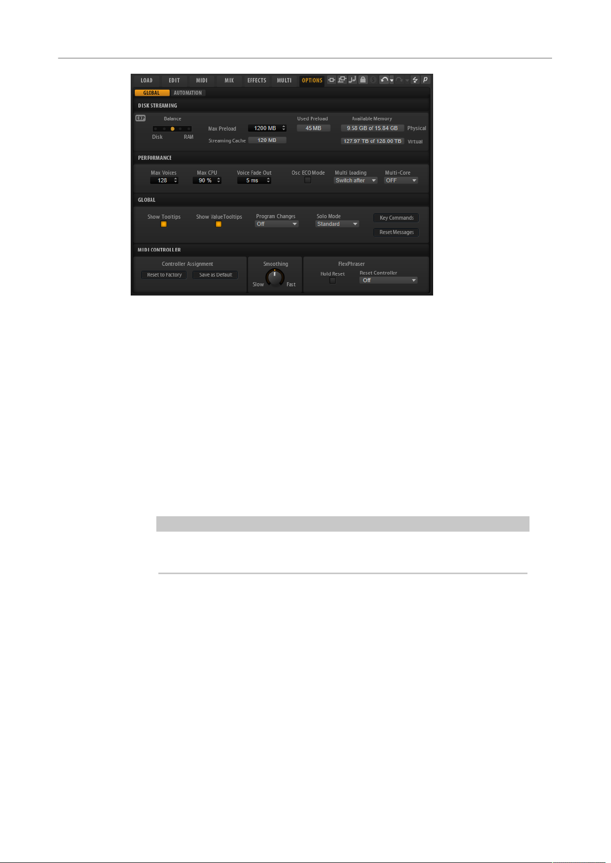
Options Page
The Options page contains global settings regarding performance optimization, global
functions, and MIDI controllers.
26
Page 27
Global Functions and Settings
Options Page
Disk Streaming Section
Some of the programs come with up to 1 GB of samples. That is a large amount of data and
your computer cannot load all samples completely into the RAM, especially if you are using
all slots. Therefore, HALion Sonic loads only the initial milliseconds of each sample into
RAM. You can specify how much RAM should be used and how much HALion Sonic should
rely on accessing the hard-disk.
Balancing Disk vs. RAM
Use the Balance slider to balance the hard disk versus the RAM usage.
• If you need more RAM for other applications, drag the slider to the left
towards the Disk setting.
• If your hard disk is not supplying data fast enough, drag the slider to the
right towards the RAM setting.
NOTE
The Disk vs. RAM setting always applies to all plug-in instances. It is not saved
with the project. You set it up only once for your computer system.
Used Preload and Available Memory
These displays provide information of the memory load in MB according to the
current balance slider setting.
Max Preload
Determines the maximum amount of RAM that HALion Sonic uses for preloading
samples. In most cases, the default values are sufficient. However, it may
become necessary to reduce this value, for example, when working with other
applications or plug-ins that require a lot of memory.
Expert Mode
Activate Expert Mode if you want to adjust the Disk Streaming settings in greater
detail.
27
Page 28

Global Functions and Settings
Options Page
• Preload Time defines how much of the start of the samples is preloaded
• Prefetch Time determines the read-ahead capacity into the RAM while
• Streaming Cache determines the amount of RAM that is reserved for
Performance Section
into the RAM. Larger values allow for more samples to be triggered in a
short time.
streaming samples for a voice that is playing. Larger values allow for
better transfer rates from disk, and usually for more voices. However, this
requires larger streaming cache in RAM. If you increase the Prefetch Time,
it is recommended to also increase the Streaming Cache.
prefetching. The actually needed size depends on the prefetch time, the
number of simultaneously streaming voices and the audio format of the
samples. For example, higher sample and bit rates need more RAM.
The Performance section contains settings to optimize the overall CPU performance of the
plug-in.
Max Voices
Determines the total number of voices that a plug-in instance can play back. As
soon as this limit is reached, HALion Sonic starts stealing voices.
Max CPU
To avoid clicks from CPU overloads, you can specify a maximum limit for the CPU
load of the plug-in instance. HALion Sonic steals voices automatically when this
limit is exceeded. At a setting of 100 %, this parameter is deactivated.
NOTE
Because of the reaction time of the plug-in, it is possible that you get CPU peaks
that exceed the set limit. This can lead to artifacts, such as audio drop-outs.
Therefore, it is good practice to set the Max CPU setting at a value a bit lower
than actually needed.
Voice Fade Out
Sets the time to fade out voices that need to be stolen because the Max Voices
setting or the Max CPU setting have been reached.
Osc ECO Mode
Activate this option to run the oscillators of synth layers in ECO mode. In ECO
mode, the oscillators use less CPU at the cost of producing more aliasing at
higher pitches. If this option is activated, you can play more voices with synth
layers.
28
Page 29

Global Functions and Settings
Options Page
Multi Loading
Normally, when loading multi-programs, the previous multi is kept in the RAM
until the new multi has been completely loaded. Therefore, replacing a large
multi by another can lead to RAM overload on 32-bit systems.
• To clear a multi before loading a new one, select Clear before on the pop-
Multi-Core
On this pop-up menu, you can specify how many of the available CPU cores of
your system can be used by the plug-in. This allows HALion Sonic to compute
each program on a different core, for example. The best setting here depends on
multiple factors, and varies from system to system, and project to project. A good
starting point is to set this value to one core less than the available number of
cores.
NOTE
If problems occur, reduce the number of cores, or set the pop-up menu to Off and
load multiple instances of HALion Sonic instead. This way, the host application
distributes the work load across the available cores.
up menu.
Global Section
Here, you find common settings of HALion Sonic and the General MIDI mode parameter.
NOTE
The settings in this section are not saved with a project, but affect the plug-in as a whole.
Show Tooltips
If this option is activated, a tooltip is shown when you move the mouse over a
control.
Show Value Tooltips
If this option is activated, parameters without a value field display their value in a
tooltip when you use the corresponding control.
Solo Mode
• In Standard mode, you can solo multiple programs or layers to hear them
combined.
• In Exclusive mode, only one program or layer can be soloed at a time.
Program Changes
Determines how HALion Sonic handles incoming MIDI program change
messages.
• In GM Mode, program change messages are used to switch programs in
the slots of the multi program rack.
• In Multi Mode, program change messages are used to switch between the
128 multis that can be configured on the Multi page.
• Select Off to ignore incoming controller change messages.
29
Page 30

Global Functions and Settings
Options Page
General MIDI Mode
Select General MIDI Mode to play back MIDI files that have been arranged for
General MIDI sound sets. General MIDI mode supports MIDI program change
messages and preloads a global chorus and reverb effect on AUX FX 1 and 3 for
immediate use.
If General MIDI mode is activated, all loaded programs are removed and the 16
slots are assigned to the 16 MIDI channels. As long as General MIDI mode is
active, the 16 MIDI channels on the MIDI page cannot be changed.
The MediaBay sets an instrument set filter and displays only the General MIDI
sounds. The MIDI program changes 0–127 refer to the corresponding GM Sound
attributes of the MediaBay. This means that you can make any of your sounds
part of the General MIDI sound set by setting the GM Sound attribute on the
corresponding sound.
NOTE
The General MIDI sounds that come with HALion Sonic are optimized for fast
loading times. However, larger programs take longer to load.
Key Commands
Opens the Key Commands dialog, where you can view and assign key commands.
Reset Messages
If you click this button, all message dialogs that have been suppressed with the
Don't Show Again option are displayed again.
MIDI Controller Section
Controller Assignment
With the two buttons in this section, you can save your customized MIDI
controller assignments as default or restore the factory MIDI controller
assignments.
NOTE
Save as Default does not include any of the MIDI controller assignments of the
AUX FX.
The current MIDI controller mapping is also saved with each project. This way,
you can transfer your settings to other systems. The project includes the MIDI
controller assignments of the AUX FX as well.
MIDI Controller Smoothing
MIDI controllers have a maximum resolution of 128 steps. This is rather low.
Therefore, if you use a MIDI controller as a modulation source in the modulation
matrix or to remote-control a quick control, the parameter change may occur in
audible steps, causing an effect often referred to as “zipper noise”. To avoid this,
HALion Sonic provides MIDI controller smoothing, so that parameter changes
occur more gradually.
30
Page 31

Global Functions and Settings
Options Page
• If MIDI controller changes cause audible artifacts, turn the control
• If you want more immediate MIDI controller changes, turn the control
FlexPhraser
Hold Reset sends a global hold reset message to all FlexPhraser modules that
are used.
The Reset Controller pop-up menu allows you to assign a dedicated MIDI
controller to the Hold Reset button for remote-controlling it.
towards slower settings. This way, MIDI controller changes do not occur
immediately, but are spaced over a period of time (in milliseconds).
towards faster settings. Note, however, that this may introduce audible
artifacts.
31
Page 32

The Edit page is where you edit your program, load different layers for a program, and edit
the layers. A program contains up to four layers that can all be mapped to different velocity
and key ranges. Each of the layers can use a FlexPhraser and can be routed freely to one of
the available outputs.
To edit a program, click the Program button at the top of the Edit page.
Program Page Parameters
The Program page is divided into two sections. The section at the top is used to load
and save layers, and to set up the mix parameters such as level, pan, and FX sends. The
bottom section is used to display layer ranges, program FlexPhraser editors, quick control
assignments, or Note Expression parameters.
Editing Programs
On/Off
Activates/Deactivates the corresponding layer. If a layer is deactivated, it does not
use any processing power.
Mute
Mutes the corresponding layer.
Solo
Solos the corresponding layer. You can solo multiple layers at the same time.
NOTE
The Mute and Solo buttons at the top of the page mute the entire program.
FlexPhraser On/Off
Activates/Deactivates the FlexPhraser for a layer.
You can edit the FlexPhraser on the edit page for the corresponding layer.
32
Page 33

Editing Programs
Program Page Parameters
NOTE
This button is only available for layers that support the FlexPhraser functionality.
Layer Slots
The layer slots allow you to load up to four layers for a program.
Right-click a slot to open the context menu with the following options:
• Load Layer opens the Load Layer dialog. Select a layer and click OK to load
• Save Layer saves the layer in this slot with the current settings, under the
• Save Layer As opens the Save Layer dialog where you can save the layer
• Remove Layer removes the layer from the slot.
• Init Layer loads a neutral synth layer.
• Copy Layer copies the layer to the clipboard.
• Paste Layer pastes the copied layer into the current slot.
it into this slot.
same name.
NOTE
Write-protected content can only be saved under a new name.
under a new name.
Level
Adjusts the loudness of the layer.
Pan
Sets the position of the layer in the stereo panorama.
FX1–4 Send Levels
These four sliders adjust the send levels for the global AUX FX busses for each
layer.
Output
Sets the output for each layer. If you do not change this setting, the signal is sent
to the output that is specified for the program. But you can also select the main
output or one of the plug-in outputs.
Ranges Tab
33
Page 34

Editing Programs
Program Page Parameters
Poly
Specifies how many notes can be played at the same time.
NOTE
Polyphony is part of the layer settings and is therefore restored when you load a
layer.
If a layer is monophonic, this setting has no effect.
Octave
Allows you to shift the octave of a layer by ±5 octaves.
Coarse
Allows you to shift the pitch of a layer by ±12 semitones.
Fine
Allows you to detune a layer by ±100 cents.
Key Range (Low Key, High Key)
Allows you to limit the key range for a slot.
Velocity Range (Low Vel, High Vel)
Allows you to limit the velocity range for a slot.
Controller Filter
Allows you to filter out the most commonly used MIDI controllers.
FlexP, QC, and NoteExp Tabs
The FlexP, QC, and NoteExp tabs are described in separate sections.
RELATED LINKS
FlexPhraser on page 76
Quick Controls on page 18
Note Expression on page 264
Editing the Key Range on page 34
Editing the Velocity Range on page 35
Filtering Controllers on page 35
Editing the Key Range
Each slot can be limited to a specific key range.
To show the key range, activate the Key button above the range controls.
You can set the key range in the following ways:
• Set the range with the Low Key and High Key value fields or by dragging the ends of
the keyboard range control.
• To move the key range, click in the middle of the range control and drag.
34
Page 35

Editing Programs
Program Page Parameters
• To set the range via MIDI input, double-click in a value field and play the note.
Editing the Velocity Range
Each slot can be limited to a specific velocity range.
To show the velocity range, activate the Vel button above the range controls.
• Set the velocity range with the Low Vel and High Vel value fields or by dragging the
ends of the velocity range control.
To move the velocity range, click in the middle of the range control and drag.
Filtering Controllers
You can filter out the most commonly used MIDI controllers for each slot separately.
For example, if you set up a keyboard split with bass and piano playing on the same MIDI
channel, both sounds receive the same MIDI controllers. However, you usually do not want
the bass to receive the sustain pedal. To avoid that all sounds on the same MIDI channel
receive the same MIDI controllers, use the controller filter.
Filtering out control change messages can also be used to avoid unwanted program changes
on MIDI channel 10 (drums), for example.
PROCEDURE
1. Activate the Ctrl button above the range controls.
2. For each slot, activate the MIDI controllers that you want to filter out.
You can filter out the following MIDI controllers: Sustain Pedal #64, Foot Controller #4,
Foot Switches #65-69, Pitchbend, Modulation Wheel #1, and Aftertouch.
35
Page 36

Voice Tab
Editing Layers
A program contains up to four layers. Each layer can be edited separately. The available
parameters and tabs vary depending on the type of layer.
On the Edit page, you can select which layer to edit by clicking the corresponding button at
the top of the page.
Mono
Allows you to switch between monophonic and polyphonic playback.
• Activate Mono to switch to monophonic playback. Usually, this allows a
more natural sounding performance for solo instruments.
• Deactivate Mono to play polyphonically with the number of notes specified
by the Polyphony control.
Retrigger
This option is only available in Mono mode. If Retrigger is activated, a note that
was stolen by another note is retriggered if you still hold the stolen note when
you release the new one.
This way, you can play trills by holding one note and quickly and repeatedly
pressing and releasing another note, for example.
Polyphony
Sets the upper limit for the number of notes that you can play if Mono is
deactivated.
36
Page 37

Editing Layers
Voice Tab
NOTE
If the program has a lower value for polyphony than any of its layers, the
maximum number of notes is determined by the program.
Trigger Mode
Defines the trigger behavior for new notes.
• Normal triggers a new note when the previous note gets stolen. The
sample and the envelope of the new note are triggered from the start.
To minimize discontinuities, use the Fade Out parameter of the zone.
• Resume does not always trigger a new note.
If the new note stays within the same zone, the envelope is retriggered, but
resumes at the level of the stolen note. The pitch of the zone is set to the
new note.
If the new note plays in a different zone, the sample and the envelope of the
new note are triggered from the start.
• Legato does not always trigger a new note.
If the new note stays within the same zone, the envelope keeps running.
The pitch of the zone is set to the new note.
If the new note plays in a different zone, the sample and the envelope of the
new note are triggered from the start.
• Resume Keeps Zone does not trigger a new note upon note stealing. The
envelope resumes at the level of the stolen note and the pitch of the zone is
set to the new note, even if the new note plays in a different zone.
• Legato Keeps Zone does not trigger a new note upon note stealing. The
envelope keeps running and the pitch of the zone is set to the new note,
even if the new note plays in a different zone.
Voice Mode
Determines which notes are stolen during playback and whether new notes are
triggered when the Polyphony setting is exceeded.
• Last Note Priority – New notes have playback priority over the notes that
were played before them.
If you exceed the maximum number of notes, the notes that were played
first are stolen in chronological order (First in/First Out) and the new notes
are triggered.
• First Note Priority – Older notes have playback priority over newer notes.
If you exceed the maximum number of notes while older notes are still
being held, no notes are stolen. New notes are only triggered if a free voice
is available.
• Low Note Priority – Low notes have playback priority over higher notes.
If you exceed the maximum number of notes by playing a lower note than
the ones that are held, the highest note is stolen and the new note is
triggered.
If you exceed the maximum number of notes by playing a higher note than
the ones that are held, no note is stolen and no new note is triggered.
37
Page 38

Editing Layers
Voice Tab
• High Note Priority – High notes have playback priority over lower notes.
If you exceed the maximum number of notes by playing a higher note
than the ones that are held, the lowest note is stolen and the new note is
triggered.
If you exceed the maximum number of notes by playing a lower note than
the ones that are held, no note is stolen and no new note is triggered.
• Steal Lowest Amplitude – New notes have playback priority over notes with
a low amplitude.
If you exceed the maximum number of notes, the note with the lowest
amplitude is stolen and the newest note is triggered.
• Steal Released Notes – New notes have priority over notes that enter the
release phase.
If you exceed the maximum number of notes, the oldest note that is in its
release phase is stolen and the new note is triggered.
If no note is playing in release and you exceed the maximum number of
notes, the first played notes are stolen in chronological order and the new
notes are triggered.
Key Poly
With this parameter, you can specify an upper limit for the number of notes that
can be played for a key. The notes that were played last have priority. For this
parameter to have an effect, the Mono button must be deactivated.
NOTE
Key Poly is limited by the Polyphony setting.
Low Amp
By default, the oldest note is removed first when notes are stolen due to a Key
Poly limitation. If you want the note with the lowest amplitude to be removed
instead, activate Low Amp.
Min Low Notes
Defines the number of low notes that cannot be stolen, regardless of the Voice
Mode setting.
Make sure that the polyphony of the program is high enough for your specific Min
Low Notes setting and allows to play additional higher notes.
Key On Delay
With this parameter, you can delay the playback of the layer by a specified time or
a note value.
If Sync is deactivated, the delay is specified in milliseconds. If Sync is activated,
the delay is specified in fractions of beats.
To synchronize the delay time to the host tempo, activate the Sync button and
select a note value from the pop-up menu. To change the selected note value to a
triplet, activate the T button.
38
Page 39

Editing Layers
Voice Tab
Unison
Allows you to trigger multiple voices simultaneously with each note that you play.
If you activate Unison, the following parameters become available:
• Voices determines the number of voices that are triggered simultaneously
(max. 8).
• Detune detunes the pitch of each unison voice in cents. This produces a
fatter sound.
• Pan spreads the unison voices across the stereo panorama. The higher the
value, the broader the stereo image.
• Delay allows you to introduce a small random delay for each unison voice.
With a value of 0 %, all unison voices are triggered at the same time. Values
from 1 % to 100 % add a random delay to each unison voice. The higher the
value, the more random the delay. This is especially useful to avoid comb
filter effects with two or more slightly detuned samples.
Glide
Allows you to bend the pitch between notes that follow each other. You achieve
the best results in Mono mode. If you activate Glide, the following parameters
become available:
• Time specifies the time needed to bend the pitch from one note to the
other.
• Activate Sync to synchronize the delay time to the host tempo. Select a note
value from the pop-up menu. To change the selected note value to a triplet,
activate the T button.
• Mode determines the glide time.
Set this parameter to Constant Time to keep the glide time constant and
independent from the note interval.
Set this parameter to Constant Speed to change the glide time with the
note interval. Larger intervals result in longer glide times.
• Curve allows you to select one of three curve types to define the glide
behavior.
With the Linear curve, the pitch glides at continuous speed from the start
to the end pitch.
With the Exponential curve, the pitch starts gliding at higher speed and
decelerates towards the end pitch. This behavior is similar to the natural
pitch glide produced by a singer.
With the Quantized curve, the pitch glides in semitones from the start to
the end pitch.
• Fingered allows you to glide the pitch only between notes that are played
legato.
NOTE
If you use Cutoff Key Follow, Level Key Follow, and Pan Key Follow, the
corresponding parameters also change with the Glide effect.
39
Page 40

Editing Layers
Pitch Tab
Pitch Tab
Pitchbend Up/Pitchbend Down
Determines the range for the modulation that is applied when you move the
pitchbend wheel.
Octave
Allows you to shift the octave of a layer by ±5 octaves.
Coarse
Allows you to shift the pitch of a layer by ±12 semitones.
Fine
Pitch Envelope Amount
Random Pitch
Pitch Key Follow
Center Key
Oscillator Tab
Allows you to detune a layer by ±100 cents.
Determines how much the pitch is affected by the pitch envelope.
Allows you to randomly offset the pitch with each played note. Higher values
cause stronger variations. At a setting of 100 %, the random offsets can vary from
-6 to +6 semitones.
Allows you to adjust the pitch modulation by MIDI note number. Set this
parameter to positive values in order to raise the pitch the higher you play. Use
negative values to lower the pitch the higher you play. At a setting of +100 %, the
pitch follows the played note exactly.
Specifies the MIDI note that is used as the central position for the Pitch Key
Follow function.
The Oscillator tab offers six sound sources: three main oscillators, the sub oscillator, the
ring modulation, and the noise generator. To create interesting electronic spectra, you can
mix any of these sound sources. The resulting signal is sent to the Filter and Amplifier tabs
for further sound shaping.
The three main oscillators (OSC 1, OSC 2, and OSC 3) offer several wave shapes and
algorithms.
• To activate an oscillator, click its On/Off button.
40
Page 41

Editing Layers
Oscillator Tab
OSC 1/2/3 Type
The oscillator type defines the basic sound character of the oscillator. This popup menu lists the waveforms (sine, triangle, saw, or square), followed by the
algorithm (PWM, Sync, CM, or XOR). The combination of waveform and algorithm
controls the sound of the oscillator.
The following algorithms are available:
• PWM (pulse width modulation) is only supported by the square waveform.
The Waveform parameter sets the ratio between the high and low value
of the square wave. A setting of 50 % produces a pure square wave. With
settings below or above 50 %, the oscillator produces rectangular waves.
• Sync provides different hard-sync oscillators, where each is a combination
of a master and slave oscillator. The wave shape of the slave oscillator
(sine, triangle, saw, or square) is reset with each full wave cycle of the
master oscillator. This means that a single oscillator can produce a
rich sync-sound without using other oscillators as slave or master. The
Waveform parameter adjusts the pitch of the slave oscillator, producing the
typical sync sound.
• CM (cross modulation) provides a combination of two oscillators where
a master oscillator is modulating the pitch of a slave oscillator (sine,
triangle, saw, or square) at the rate of the audio sample. The Waveform
parameter adjusts the pitch ratio between slave and master oscillator,
resulting in a sound close to frequency modulation.
• XOR (exclusive OR) compares two square waveforms with an XOR
operation. Depending on the outcome of the XOR operation, the waveform
shape of a third oscillator (sine, triangle, saw, or square) is reset. The
Waveform parameter adjusts the pitch ratio of the square oscillators
resulting in a sound close to ring modulation of the third oscillator.
Osc 1/2/3 Waveform
Modifies the sound of the oscillator algorithm. Its effect depends on the selected
oscillator type.
NOTE
• Except for PWM, all algorithms support the sine, triangle, saw, and square
wave shapes. PWM supports only the square wave shape.
• The Waveform parameter for the three main oscillators can be assigned as
modulation destinations in the modulation matrix.
OSC 1/2/3 Octave
Adjusts the pitch in octave steps.
41
Page 42

Editing Layers
Oscillator Tab
OSC 1/2/3 Coarse
Adjusts the pitch in semitone steps.
OSC 1/2/3 Fine
Adjusts the pitch in cent steps. This allows you to fine-tune the oscillator sound.
OSC 1/2/3 Level
Adjusts the output level of the oscillator.
NOTE
Waveform, pitch, and level of oscillator 1, 2, and 3 can be modulated separately in
the modulation matrix.
Multi-Oscillator Mode
For the three main oscillators, you can activate Multi-Oscillator mode. This allows you to
create a richer sound by producing up to eight oscillators simultaneously.
• To activate Multi-Oscillator mode, activate the MO button.
If Multi-Oscillator mode is activated, you can click the edit button to show the
corresponding parameters.
NOTE
If Multi-Oscillator mode is active for an oscillator, you can modulate the corresponding
parameters in the modulation matrix.
Multi Oscillator Number, Detune, and Spread
Each of the main oscillators offers these multi-oscillator functions. They allow
you to create a richer sound by producing up to eight oscillators simultaneously.
• Number determines the number of oscillators that play back
simultaneously. You can also set fractions of numbers. For example, with
a setting of 2.5, you hear two oscillators at full level and a third one at half
level.
• Detune detunes the oscillators.
• Spread narrows or widens the stereo panorama. With a setting of 0 %, you
create a mono signal, and with 100 %, you create a stereo signal.
Sub Oscillator
The pitch of the sub oscillator is always one octave lower than the overall pitch. The overall
pitch is determined by the Octave setting.
On/Off
Activates/Deactivates the sub oscillator.
Type
The wave shape of the sub oscillator. You can choose between Sine, Triangle,
Saw, Square, Pulse Wide, and Pulse Narrow.
42
Page 43

Editing Layers
Filter Tab
Level
Adjusts the output level of the sub oscillator.
Ring Modulator
Ring modulation produces sums and differences between the frequencies of two signals.
Ring Modulation Source 1/Ring Modulation Source 2
Determines the sources to be ring modulated. You can select OSC 1 or Sub as
Source 1, and OSC 2 or OSC 3 as Source 2.
NOTE
Make sure that the corresponding oscillators are activated when you select them.
Otherwise, no sound is heard.
Ring Modulation Level
Adjusts the output level of the ring modulation.
Filter Tab
Noise Generator
The Noise parameter is used for non-pitched sounds. In addition to standard white and pink
noise, there are also band-pass filtered versions of white and pink noise.
Noise Type
The sound color of the noise. You can choose between standard and band-pass
filtered (BPF) versions of white and pink noise.
Noise Level
Adjusts the output level of the noise generator.
Filter Mode
The buttons on the left determine the overall filter structure.
• Single Filter uses one filter with one selectable filter shape.
• Dual Filter Serial uses two separate filters connected in series.
You can select the filter shapes for each filter independently. The
parameters Cutoff and Resonance control both filters simultaneously.
However, you can offset these parameters for the second filter with the
parameters CF Offset and Res Offset.
43
Page 44

Editing Layers
Filter Tab
• Dual Filter Parallel uses two separate filters connected in parallel.
You can select the filter shapes for each filter independently. The
parameters Cutoff and Resonance control both filters simultaneously.
However, you can offset these parameters for the second filter with the
parameters CF Offset and Res Offset.
• Morph 2 morphs between filter shape A and B.
Adjust the morphing with the Morph Y parameter.
• Morph 4 morphs sequentially from filter shape A to D.
Adjust the morphing with the Morph Y parameter.
• Morph XY morphs freely between the filter shapes A, B, C, and D.
Adjust the morphing with the Morph X and Morph Y parameters.
Filter Type
Specifies the basic sound character of the filter.
• Off deactivates the filter section.
• Classic offers 24 filter shapes with resonance.
• Tube Drive adds warm, tube-like distortion. You can set the amount of tube
drive with the Distortion parameter.
• Hard Clip adds bright, transistor-like distortion. You can set the amount of
hard clipping with the Distortion parameter.
• Bit Red (Bit Reduction) adds digital distortion by means of quantization
noise. You can adjust the bit reduction with the Distortion parameter.
• Rate Red adds digital distortion by means of aliasing. You can adjust the
rate reduction with the Distortion parameter.
• Rate Red KF adds digital distortion by means of aliasing. In addition, Key
Follow is used. The rate reduction follows the keyboard, so the higher you
play, the higher the sample rate.
• HALion 3 offers the five legacy filter shapes from HALion3.
• Waldorf offers 13 filter shapes, including two comb filters.
• Eco is a performance-optimized low-pass filter without Resonance or
Distortion parameters. It allows you to adapt the brilliance of samples for
different velocity layers of the same key, for example.
NOTE
Filters without distortion use less processing power.
Filter Shape
• LP24, 18, 12, and 6 are low-pass filters with 24, 18, 12, and 6 dB/oct.
Frequencies above the cutoff are attenuated.
• BP12 and BP24 are band-pass filters with 12 and 24 dB/oct. Frequencies
below and above the cutoff are attenuated.
• HP6+LP18 and HP6+LP12 are combinations of a high-pass filter with 6 dB/
oct and a low-pass filter with 18 and 12 dB/oct, respectively (asymmetric
band-pass filter). Frequencies below and above the cutoff are attenuated.
Attenuation is more pronounced for the frequencies above the cutoff.
44
Page 45

Editing Layers
Filter Tab
• HP12+LP6 and HP18+LP6 are combinations of a high-pass filter with 12
and 18 dB/oct and a low-pass filter with 6 dB/oct (asymmetric band-pass
filter). Frequencies below and above the cutoff are attenuated. Attenuation
is more pronounced for the frequencies below the cutoff.
• HP24, 18, 12, and 6 are high-pass filters with 24, 18, 12, and 6 dB/oct.
Frequencies below the cutoff are attenuated.
• BR12 and BR24 are band-reject filters with 12 and 24 dB/oct. Frequencies
around the cutoff are attenuated.
• BR12+LP6 and BR12+LP12 are combinations of a band-reject filter with 12
dB/oct and a low-pass filter with 6 and 12 dB/oct, respectively. Frequencies
around and above the cutoff are attenuated.
• BP12+BR12 is a band-pass filter with 12 dB/oct plus a band-reject filter
with 12 dB/oct. Frequencies below, above, and around the cutoff are
attenuated.
• HP6+BR12 and HP12+BR12 are combinations of a high-pass filter with 6
and 12 dB/oct and a band-reject filter with 12 dB/oct. Frequencies below
and around the cutoff are attenuated.
• AP is an all-pass filter with 18 dB/oct. Frequencies around the cutoff are
attenuated.
• AP+LP6 is an all-pass filter with 18 dB/oct plus a low-pass filter with 6 dB/
oct. Frequencies around and above the cutoff are attenuated.
• HP6+AP is a high-pass filter with 6 dB/oct plus an all-pass filter with 18
dB/oct. Frequencies around and below the cutoff are attenuated.
X/Y Control
Allows you to adjust two parameters simultaneously.
• For the filter types Single, Dual Serial, and Dual Parallel, the X/Y control
adjusts the cutoff frequency on the horizontal axis and the resonance on
the vertical axis.
• For the filter types Morph 2 and Morph 4, the X/Y control adjusts the
morphing between the filter shapes on the vertical axis. The horizontal axis
adjusts the cutoff frequency.
• For Morph XY, the X/Y control adjusts the morphing between the filter
shapes AD and BC on the horizontal axis, and AB and DC on the vertical
axis.
Cutoff
Controls the cutoff frequency of the filter.
Resonance
Emphasizes the frequencies around the cutoff. At higher settings, the filter selfoscillates, which results in a ringing tone.
Distortion
Adds distortion to the signal. The effect depends largely on the selected filter
type. At higher settings, it creates a very intense distortion effect.
45
Page 46

Editing Layers
Amplifier Tab
NOTE
This parameter is only available for the filter types Tube Drive, Hard Clip, Bit Red,
Rate Red, and Rate Red KF.
CF Offset
For the dual filters, this parameter allows you to offset the cutoff frequency of the
second filter, that is, of filter shape B.
Res Offset
For the dual filters, this parameter allows you to offset the resonance of the
second filter, that is, of filter shape B.
Cutoff Velocity
Controls the cutoff modulation from velocity.
Envelope Amount
Controls the cutoff modulation from the filter envelope.
Cutoff Key Follow
Center Key
Amplifier Tab
Level
Level Key Follow
Adjusts the cutoff modulation using the note number. Increase this parameter
to raise the cutoff with higher notes. At 100 %, the cutoff follows the played pitch
exactly.
Specifies the MIDI note that is used as the central position for the Key Follow
function.
Controls the overall volume of the sound.
Allows you to control the volume depending on the note pitch. Positive values
mean that the volume is higher the higher the notes you play. With negative
values, the volume decreases the higher the notes you play.
Center Key
Specifies the MIDI note that is used as the center position for Level Key Follow.
Pan
Determines the position of the sound in the stereo panorama. At a setting of -100
%, the sound is panned hard left, and at +100 %, it is panned hard right.
46
Page 47

Editing Layers
Amplifier Tab
Mode
With this option you can specify how the loudness changes across the stereo
panorama.
• If this parameter is set to 0 dB, it works like a balance control.
Setting the pan control towards the left fades out the right channel and vice
versa. At the center position, the loudness is not cut.
• If this parameter is set to -3 dB, the option uses the cosine/sine pan law.
The loudness is cut by -3 dB at the center position, but the energy is
preserved when moving the source signal across the stereo panorama.
The -3 dB option sounds more natural. The transition from hard left to hard
right sounds much smoother than with the 0 dB or the -6 dB setting.
• If this parameter is set to -6 dB, this option uses the linear pan law.
The loudness is cut by -6 dB at the center position, and the energy is not
preserved when moving the source signal across the stereo panorama. The
-6 dB option sounds more synthetic. The transition from hard left to hard
right sounds more abrupt than with the -3 dB setting.
• If this parameter is set to Off, no panning is applied.
Random Pan
Allows you to offset the pan position randomly with each played note. Higher
values cause stronger variations. At a setting of 100 %, the random offsets can
vary from fully left to fully right.
Alternate Pan
Allows you to alternate the pan position each time that you play a note. To start
panning on the left, use negative values. Use positive values to begin on the right.
At a setting of +100 %, the first note plays hard right, the second note hard left,
and so on.
Reset
The initial pan position is set once when HALion Sonic is loaded. After that, each
note that you play is counted to determine the next pan position. To reset this
counter, click the Reset button.
Pan Key Follow
Allows you to adjust the pan modulation via the MIDI note number. Set this
parameter to positive values to offset the pan position towards the right for notes
above, and towards the left for notes below the center key. Use negative values to
offset the pan position towards the left for notes above, and towards the right for
notes below the center key.
At the maximum setting of +200 %, the pan position moves from hard left to hard
right within two octaves: Fully left is reached one octave below and fully right is
reached one octave above the center key.
Center Key
Specifies the MIDI note that is used as the center position for Pan Key Follow.
47
Page 48

Editing Layers
Envelopes
Additional Parameters for Drum and Loop Layers
One Shot
If this button is activated, any MIDI note-off messages are ignored. The release
segments of the envelopes is not played. Instead, the envelopes play until the
sustain is reached and remain on that level for as long as the sample plays back.
Any loop settings of the sample are ignored.
Reverse
If this button is activated, the sample is played in reverse. Any loop settings the
sample may contain are ignored.
Envelopes
On the Edit page, you can edit the pitch (P), filter (F), amp (A), and user (U) envelopes. Each of
these is a multi-segment envelope with up to 128 nodes. The nodes specify the overall shape
of the envelope. The amp, filter, and pitch envelopes are pre-assigned to the amplitude, the
filter cutoff frequency, and the pitch of the layer. The user envelope is freely assignable.
All envelopes can be used as sources in the modulation matrix.
• Click P to display the parameters of the pitch envelope.
The pitch envelope modulates the pitch over time. The pitch envelope is bipolar, which
means it allows for negative and positive values to bend the pitch.
• Click F to display the parameters of the filter envelope.
The filter envelope controls the cutoff frequency to shape the harmonic content over
time.
• Click A to display the parameters of the amplifier envelope.
The amplifier envelope shapes the volume over time.
• Click U to display the parameters of the freely assignable user envelope.
The user envelope is bipolar, which means it allows for negative and positive values,
for example, to modulate the pan from left to right.
Mode
Determines how the envelope is played back when it is triggered.
• Select Sustain to play the envelope from the first node to the sustain node.
The sustain level is held for as long as you play the note. When you release
the note, the envelope continues with the stages following the sustain. This
mode is ideal for looped samples.
48
Page 49

Editing Layers
Envelopes
• Select Loop to play back the envelope from the first node to the loop nodes.
Then, the loop is repeated for as long as the key is held. When you release
the note, the envelope continues playing the stages that follow the sustain.
This mode is ideal for adding motion to the sustain of the envelope.
• Select One Shot to play the envelope from the first to the last node, even if
you release the key. The envelope has no sustain stage. This mode is ideal
for drum samples.
• Select Sample Loop to preserve the natural attack of the sample. The
decay of the envelope does not start until the sample has reached the
sample loop start.
If you set the second node to the maximum level and use the following
nodes to shape the decay during the loop phase of the sample, the
envelope only affects the loop phase. The attack of the envelope is still
executed.
NOTE
Sample Loop mode is only available for sample layers.
Sync
Allows you to synchronize the envelopes to the tempo of your host application.
Snap
You can select a second envelope to be displayed in the background of the edited
envelope. If Snap is activated and you change the position of nodes, they snap to
the nodes of the envelope that is shown in the background.
• To specify the envelope for the background, open the pop-up menu to the
right of the Snap button and select an envelope from the list.
Fill
Allows you to add multiple envelope nodes after the selected nodes.
Fixed
• If Fixed is activated and you move selected nodes on the time axis, only the
selected nodes are moved.
• If Fixed is deactivated, all nodes that follow the edited nodes are also
moved.
Env Node
Displays the focused envelope node.
Time
Specifies the period of time between two nodes. Depending on the Sync mode,
the Time parameter is displayed in milliseconds and seconds, or in fractions of
beats.
Curve
Allows you to adjust the curvature of the envelope curve between two nodes from
linear to logarithmic or exponential behavior.
49
Page 50

Editing Layers
Envelopes
Level
Specifies the amplitude of the envelope at the position set by the Time
parameter.
Level Velocity Curve
You can select the curve type to specify how the incoming velocity translates to
the level of the envelope. The characteristic of each curve is displayed by a small
icon.
Level Velocity (Vel>Lev)
Determines how the velocity affects the level of the envelope.
The level of the envelope depends on two factors: the setting of this parameter
and how hard you hit a key. Positive values increase the level of the envelope
the harder you hit a key. Negative values decrease the level of the envelope the
harder you hit a key.
Time Velocity (Vel>Time)
Adjusts the influence of velocity on the phases of the envelope. Positive values
decrease the length of the phases for higher velocity values. Negative values
increase the length of the phases for higher velocity values.
Segments
Here, you can select which phases of the envelope are affected by the Time
Velocity parameter.
• Attack – The velocity affects the attack only.
• Attack + Decay – The velocity affects all phases until the sustain.
• Decay – The velocity affects all phases until the sustain but without the
attack.
• Attack + Release – The velocity affects the attack and the release phases.
• All – The velocity affects all phases.
Time Key Follow, Center Key, and KeyF Rel (Key Follow Release)
With the Time Key Follow and KeyF Rel parameters, you can scale the envelope
phases across the keyboard.
• Time Key Follow scales all times before the sustain node.
• KeyF Rel scales all times after the sustain node, that is, the release phase
of the envelope.
The value that you specify for Center Key is used as the central position for the
Time Key Follow and KeyF Rel functions.
The envelope phases depend on the keyboard range in which the note is played
and on the corresponding Time Key Follow setting:
• Positive values decrease the phase lengths for notes above and increase
the phase lengths for notes below the set Center Key, that is, the envelope
becomes faster the higher the note you play.
50
Page 51

Editing Layers
Envelopes
Zooming
• Negative values increase the phase lengths for notes above and decrease
the phase lengths for notes below the Center Key, that is, the envelope
becomes slower the higher the note you play.
The vertical axis of the graphical envelope editor displays the level. The horizontal axis
displays the time.
• To zoom in or out, click the + or - buttons to the right of the scrollbar below the
graphical editor.
• To zoom in or out at the current position, click in the timeline and drag up or down.
• To toggle between full zoom and the previous zoom setting, click the A button to the
right of the horizontal zoom slider.
• To zoom to a specific region, hold Alt, click and drag the mouse over the region.
Zoom Snapshots
Zoom snapshots save the zoom factor and scroll position of the editor. These are restored
when you load the snapshot.
To the right of the scrollbar, you can find three numbered buttons that allow you to save and
load zoom snapshots.
• To save the current state of the editor as snapshot, Shift-click one of the numbered
buttons to the right of the scrollbar.
• To load a zoom snapshot, click the corresponding button. The button color changes if a
snapshot is active.
NOTE
If you perform any manual zooming or scrolling, the zoom snapshot is deactivated.
Selecting Nodes
• To select a node, click on it in the graphical editor.
The focused node is indicated by a frame. The value fields to the left of the graphical
envelope editor display the parameters of the focused node.
• If multiple nodes are selected, you can use the Env Node pop-up menu to set the focus
to a different node without losing the current selection.
• To add a node to a selection, Shift-click the node. Selected nodes are edited together.
• You can select multiple nodes by drawing a rectangle around the nodes with the
mouse.
• If the graphical editor has the focus, you can select the next or the previous node with
the left and right arrow keys.
51
Page 52

Editing Layers
Envelopes
Adjusting the Time Parameter
The Time parameter specifies the period of time between two nodes. Depending on the Sync
mode, the Time parameter is displayed in milliseconds and seconds, or in fractions of beats.
• To set the Time parameter, select the nodes that you want to adjust and enter a value
in the Time field.
• You can also adjust the Time parameter in the graphical envelope editor, by dragging
the nodes left or right, to decrease or to increase the time span.
For a higher resolution, hold Shift while moving the nodes.
To limit the movement to the time axis, that is, to change only the horizontal position of
a node, hold down Ctrl/Cmd while dragging.
Adjusting the Level Parameter
The Level parameter specifies the amplitude of the envelope at the position set by the Time
parameter.
• To set the Level parameter, select the nodes that you want to adjust and enter a value
in the Level field.
• You can also adjust the Level parameter in the graphical envelope editor by dragging
the selected nodes up or down, to decrease or increase the levels.
For a higher resolution, hold Shift while moving the nodes.
To limit the movement to the level axis, that is, to change only the vertical position of a
node, hold down Alt while dragging.
Adjusting the Curve Parameter
The Curve parameter allows you to adjust the curvature of the envelope curve between two
nodes from linear to logarithmic or exponential behavior.
• To set the Curve parameter, select the nodes that you want to adjust and enter a value
in the Curve field. Positive curve values change the curvature towards logarithmic and
negative values towards exponential behavior.
• You can also adjust the Curve parameter in the graphical envelope editor by dragging
the curve between two nodes.
Ctrl/Cmd-click a curve to reset it to linear.
Adding and Removing Nodes
• To add a node, double-click at the position where you want to add the node.
• To remove a node, double-click it.
• To delete several selected nodes, press Delete.
NOTE
• You cannot remove the first, the last, or the sustain node.
• All nodes added after the sustain node always affect the release phase of the envelope.
52
Page 53

Editing Layers
Envelopes
Adding Nodes Using the Fill Function
The Fill function allows you to add multiple envelope nodes after the selected nodes.
PROCEDURE
1. On the pop-up menu to the right of the Fill button, select the number of nodes that you
want to add.
2. In the graphical envelope editor, select the node after which you want to add nodes.
If several nodes are selected, the new nodes are inserted after the last selected node.
If Fixed is deactivated, the added nodes are placed with the interval specified by the
Time parameter of the selected node. If multiple nodes are selected, the interval is
specified by the focused node.
By activating Sync, you can specify the interval with the Sync note value. For example,
if 1/4 is selected, new nodes are added at exact quarter note intervals.
If Fixed is activated, the added nodes fill the space between the last selected node and
the following one.
3. Click the Fill button.
Using Sync
You can synchronize the envelopes to the tempo of your host application. This allows you to
set envelope times that relate to musical time intervals, regardless of any tempo changes.
PROCEDURE
1. Click Sync to activate sync mode for the envelope.
Sync mode is active if the button is highlighted. A grid spaced in fractions of beats is
displayed in the graphical envelope editor.
2. On the pop-up menu located to the right of the Sync button, select a note value.
This sets the resolution of the grid.
NOTE
The Time field of a node displays times in fractions of beats. The fraction is always
reduced to the smallest possible value. 2/16 is displayed as 1/8, for example.
3. To use triplet note values, activate the T button.
NOTE
•
Envelope nodes that do not exactly match a note value display the closest note
value.
•
Nodes that exactly match a note value are indicated by a red dot inside the
handle of the node. This is useful if you switch the grid between triplets and
normal note values, for example. The triplet nodes still indicate that they match
a note value, even if the grid shows normal note values.
You can also enter note values and triplets manually in the value field.
53
Page 54

Editing Layers
LFOs
Setting Up the Loop
You can set up the envelope to repeat its playback between the selected nodes.
PROCEDURE
1. Set the envelope mode to Loop.
2. The loop is indicated by the green region in the graphical envelope editor. Specify the
loop start and end by dragging the borders of the region.
The loop region can only be set up in the decay phase of the envelope.
LFOs
HALion Sonic offers two polyphonic and two monophonic LFOs. Polyphonic means the LFOs
are calculated per voice, allowing for independent modulations with each triggered note. You
can use this to create a richer sound, for example, with an independent pitch modulation per
note. Monophonic means the LFOs are calculated only once per layer. The same modulation
is sent to all voices simultaneously. The LFOs can be assigned freely in the modulation
matrix.
• Click P1 or P2 to show the settings for the corresponding polyphonic LFO.
• Click M1 or M2 to show the settings for the corresponding monophonic LFO.
You can adjust the times of the envelope in the graphical editor by dragging nodes left or
right.
NOTE
How many nodes are available in the graphical editor depends on the selected Envelope
Mode.
• The first node adjusts the Delay time.
• The second node adjusts the Fade In time.
• The third node adjusts the Hold time.
• The fourth node adjusts the Fade Out time.
Parameters for Monophonic and Polyphonic LFOs
LFO Waveform and Shape
• Sine produces smooth modulation, suitable for vibrato or tremolo. Shape
adds additional harmonics to the waveform.
• Triangle is similar to Sine. Shape continuously changes the triangle
waveform to a trapezoid.
54
Page 55

Editing Layers
LFOs
• Saw produces a ramp cycle. Shape continuously changes the waveform
from ramp down to triangle to ramp up.
• Pulse produces stepped modulation, where the modulation switches
abruptly between two values. Shape continuously changes the ratio
between the high and low state of the waveform. If Shape is set to 50 %, a
square wave is produced.
• Ramp is similar to the Saw waveform. Shape increasingly puts silence
before the sawtooth ramp up begins.
• Log produces a logarithmic modulation. Shape continuously changes the
logarithmic curvature from negative to positive.
• S & H 1 produces randomly stepped modulation, where each step is
different. Shape puts ramps between the steps and changes the S & H into
a smooth random signal when fully turned right.
• S & H 2 is similar to S & H 1. The steps alternate between random high and
low values. Shape puts ramps between the steps and changes the S & H
into a smooth random signal when fully turned right.
Sync Mode
The Sync Mode is used to match the LFO to the tempo of the host application.
• Select Off to adjust the speed of the modulation in Hertz.
• Select Tempo + Retrig to adjust the speed of the modulation in fractions of
beats. You can also set dotted and triplet note values. The restart behavior
of the LFO depends on the Retrigger Mode.
• Select Tempo + Beat to adjust the speed of the modulation in fractions of
beats. You can also set dotted and triplet note values. The LFO restarts
with the transport of the host and lines up to the beats of the song. The
Retrigger Mode setting is not taken into account.
NOTE
The behavior of the Frequency parameter changes with the selected option.
Retrigger Mode (Monophonic LFOs)
Determines whether the LFO is restarted when a note is triggered. If this is set
to First Note or Each Note, the waveform starts at the position specified by the
Phase parameter.
• If this is set to Off, the LFO runs freely.
• If this is set to First Note, the LFO restarts when a note is triggered and no
other notes are held.
• If this is set to Each Note, the LFO restarts each time a note is triggered.
Frequency
Controls the frequency of the modulation, that is, the speed of the LFO.
Phase
Sets the initial phase of the waveform when the LFO is retriggered.
55
Page 56

Editing Layers
LFOs
Rnd (Random Phase)
If this button is activated, each note starts with a randomized start phase.
NOTE
The Phase control cannot be used if Rnd is activated.
Additional Parameters for Polyphonic LFOs
Retrigger Mode
Determines whether the LFO is restarted when a note is triggered. The waveform
restarts at the position set with the Phase parameter.
The polyphonic LFOs can switch between On and Off.
• If this parameter is set to Off, the LFO runs freely.
• If this parameter is set to On, the LFO starts with each triggered note.
Envelope Mode
Allows you to specify how the LFO envelope reacts to your playing on the
keyboard. The One Shot modes do not react to note-off events.
• Select One Shot to play the envelope from start to end in the time specified
by the Delay, Fade In, Hold, and Fade Out parameters.
• One Shot + Sustain is similar to One Shot. The Delay and Fade In
parameters are always applied when you play a note. The Hold and Fade
Out parameters are not available.
• If Hold + Fade Out is selected and you play a note, the Delay and Fade In
parameters are applied. The envelope fades out after the time specified by
the Hold parameter or when a key is released. Releasing a key during the
fade in starts the fade out from the current level.
• If Sustain + Fade Out is selected and you play a note, the Delay and Fade In
parameters are applied. The Hold parameter is not available. The fade out
is applied when releasing the key. Releasing a key during the fade in starts
the fade out from the current level.
• If Sustain is selected and you play a note, the Delay and Fade In
parameters are applied. The Hold and Fade Out parameters are not
available. Releasing a key during the fade in sustains the current level. This
prevents a change in modulation when a key is released.
Inv (Invert Envelope)
If this parameter is activated, the behavior of the LFO envelope is inverted, that
is, the LFO modulation starts at its maximum level and decreases to zero in the
time specified by the Fade In parameter. After the Hold time has elapsed, or
when the key is released, the modulation increases to its maximum level in the
time specified by the Fade Out parameter.
Delay
Determines the delay time between the moment you play a note and the moment
the LFO comes into effect.
56
Page 57

Editing Layers
LFOs
Fade In
Determines how long the LFO takes to fade in after the note was triggered and
the Delay time has elapsed.
Hold
Determines the amount of time the LFO is running before the fade out begins.
NOTE
Hold is only available for the envelope modes One Shot and Hold + Fade Out.
Fade Out
Determines how long the LFO takes to fade out after the hold time has elapsed or
a note has been released.
NOTE
To deactivate the fade out, use the envelope modes One Shot + Sustain or
Sustain. This ensures that the modulation does not change when a note is
released.
LFO Tab for Loop Layers
Loop layers offer a monophonic LFO with adjustable depth for Pitch, Cutoff, and Pan.
For loop layers, the following additional parameters are available:
Pitch
Adjusts how much the LFO affects the pitch of the slices.
Cutoff
Adjusts how much the LFO affects the cutoff of the slices.
Pan
Adjusts how much the LFO affects the pan of the slices.
When using the LFO of loop layers, the following applies:
• The modulation of Pitch, Cutoff, and Pan goes to all slices simultaneously. The
modulation depth cannot be set separately per slice.
• The filter must be activated to hear the modulation of the Cutoff.
57
Page 58

Editing Layers
Using the Keymap
NOTE
With a Resonance of 100 %, you might hear clicks because the slice ends abruptly, but the
filter still produces a sound from self-oscillation. In this case, go to the corresponding
FlexPhraser and reduce the Gate Scale until the clicks are gone. In addition, you can adjust
the amplifier envelope of the slices, for example, to increase the release of the envelopes.
Apart from the Pitch, Cutoff, and Pan parameters, all other parameters correspond to the
parameters on the LFO pages for sample and synth layers.
Using the Keymap
In the key map at the bottom of the editor, you see the drum instruments or loop slices that
are part of the drum or loop layer, and how they are mapped across the keyboard.
•
Keys with a drum instrument or loop slice assigned display in normal white and black.
•
The names of the drum instruments or loop slices are displayed vertically above the
keys.
•
Keys with nothing assigned are deactivated and displayed in gray.
•
For loop layers, the pitched part of the keyboard is displayed in orange.
•
Clicking a key plays and selects the corresponding drum instrument or loop slice.
NOTE
The key map is used for indication and selection only. The mapping of the drum instruments
and loop slices cannot be changed.
To edit a drum instrument or loop slice, you must select it first. You can select drum
instruments or loop slices by clicking the corresponding keys on the key map or by using
your MIDI keyboard.
To select a drum instrument or loop slice with your MIDI keyboard, activate Select Zones via
MIDI in the top section of the layer editor and press the key that plays the drum instrument
or loop slice that you want to adjust.
You can edit the selected drum instrument or loop slice using the parameters on the Pitch,
Filter, Amplifier, and AUX tabs.
AUX Tab
Each drum instrument and loop slice has individual send levels that feed the four global AUX
FX busses. This allows you to add more reverb to the snare drum and less effect to the bass
drum, for example.
58
Page 59

Editing Layers
Expression Controls for Instrument Layers
AUX FX1 – 4
These dials adjust the send levels for the four global AUX FX busses for each
drum instrument or loop slice separately.
Expression Controls for Instrument Layers
Instrument layers contain expressions. Typically, an expression is a particular playing style of
the instrument. In some cases, it can also be a part of the sound that can be turned on or off,
for example, to add realism or to maximize the performance.
The list of expressions is displayed on the left and on the right and in the lower section, you
can find the pitch, filter and amplifier settings of the selected expression.
• To load an expression, activate its On button.
• To mute an expression, activate its Mute button.
• If you want the editor to follow incoming MIDI key switches or MIDI controller values,
activate Select Expression via MIDI.
The parameters on the Pitch, Filter, and Amplifier sections are the same as on the
corresponding tabs for the other layer types.
Filter Env Modifier Section
This section offers parameters to modify the filter envelope of the expression.
Envelope Amount
Controls the cutoff modulation from the filter envelope.
59
Page 60

Editing Layers
Expression Controls for Instrument Layers
Velocity
Determines how the velocity affects the level of the filter envelope.
The level of the envelope depends on two factors: the setting of this parameter
and how hard you hit a key. Positive values increase the level of the envelope
the harder you hit a key. Negative values decrease the level of the envelope the
harder you hit a key.
Attack
Controls the attack time of the filter envelope.
Decay
Controls the decay time of the filter envelope.
Sustain
Controls the sustain level of the filter envelope.
Release
Controls the release time of the filter envelope.
Amplifier Env Modifier Section
This section offers parameters to modify the amplifier envelope of the expression.
Velocity
Use this parameter to adjust how velocity affects the level of the amplifier
envelope.
The level of the envelope depends on two factors: the setting of this parameter
and how hard you hit a key. Positive values increase the level of the envelope
the harder you hit a key. Negative values decrease the level of the envelope the
harder you hit a key.
Attack
Controls the attack time of the amplifier envelope.
Decay
Controls the decay time of the amplifier envelope.
Sustain
Controls the sustain level of the amplifier envelope.
Release
Controls the release time of the amplifier envelope.
RELATED LINKS
Pitch Tab on page 40
Filter Tab on page 43
Amplifier Tab on page 46
60
Page 61

Editing Layers
Insert Effects
Expression Maps
For more realistic performances, many instrument layers use key switches to switch
between different expressions, that is, between different articulations and playing styles of
the same instrument. These key switches are set to low keys to maximize the playable range
and they cannot be changed internally to ensure that performances played by FlexPhrasers
always sound the same.
However, in some cases you need to shift the key switches into the playable keyboard range
to get access to them. You may also want to select the expression using a MIDI controller.
You can use so-called expression maps to customize the internal setting.
•
To specify the expressions that you want to use in your expression map, activate them
in the expressions list.
NOTE
Some instrument layers consist of multiple expressions that are not switchable via a key
switch. For example, instrument noises typically do not have a key switch assigned. In this
case, you can select the individual expressions and edit them, but you cannot apply any key
switch functionality.
Expression Map Options Menu
You can define whether you want to use the internal key switches, remap them to other keys,
or use a MIDI controller by selecting a mode from the pop-up menu above the expression
list.
• Select Keyswitch to use the internal key switches to switch to an expression.
• Select Remapped if you want to remap the original key switches to other keys.
• Select Controller to use a MIDI controller to remotely control the internal key switches.
To assign a MIDI controller, open the menu, select Learn CC, and use the controller on
your MIDI hardware.
• If you activate Temporary KS Mode, expressions other than the default expression are
only active for as long as the corresponding key switch is held. This allows you to enter
notes with other expressions by pressing a key switch temporarily.
• Default Expression sets the default expression for Temporary KS Mode. This is also
the expression that is active after loading the program or layer.
Insert Effects
The Inserts tab offers you up to four insert effects for each of the layers and for the program
itself. The insert effects you assign to a layer affect only that layer. The insert effects you
61
Page 62

Editing Layers
Step Modulator
assign to the program affect all layers. Typically, you assign effects like EQ or distortion to
separate layers, but effects like delay or reverb to the entire program.
Each layer and the program have four slots for assigning insert effects. The handling is the
same for all slots and corresponds to the global effect handling.
To the right of the insert slots, you find faders for adjusting the output levels of the program
and layers.
RELATED LINKS
Using the Insert Effect Slots on page 107
Step Modulator
Synth and sample layers feature a polyphonic step modulator for creating rhythmic control
sequences.
The step modulator can be freely assigned in the modulation matrix.
Steps
Sets the number of steps in the sequence. The maximum number of steps is 32.
Sync Mode
• If Off is selected, you can adjust the speed at which the sequence repeats.
Whether the sequence restarts when you play a note depends on the
Retrigger mode.
• If Tempo + Retrig is selected, you can adjust the length of the steps in
fractions of beats. The speed of the modulation depends on the number of
steps, the note value, and the tempo you set in your host application. To use
triplet note values, activate Triplet.
Whether the sequence restarts when you play a note depends on the
selected Retrigger Mode.
• If Tempo + Beat is selected, you can adjust the length of the steps in
fractions of beats. The speed of the modulation depends on the number of
steps, the note value, and the tempo you set in your host application. To use
triplet note values, activate Triplet.
The sequence restarts with the transport of the host application and lines
up to the beats of the project. The Retrigger Mode is not taken into account.
Frequency
If Sync Mode is set to Off, this controls the speed at which the sequence is
repeated.
62
Page 63

Editing Layers
Step Modulator
Note
If Sync Mode is set to one of the Tempo settings, this adjusts the length of the
steps in fractions of beats. You can also select triplet values.
Triplet
Activate this button to use triplet note values.
Retrigger Mode
Determines whether the sequence restarts when you play a note. This parameter
is only available if Sync Mode is set to Off or Tempo + Retrig.
• If this parameter is set to Off, the sequence is not restarted. Instead, it
resumes playback at the position at which you released the key.
• If this parameter is set to First Note, the sequence restarts when a note is
triggered and no other notes are held.
• If this parameter is set to Each Note, the sequence restarts each time a
note is triggered.
Slope
Determines whether the step modulator jumps from step to step or creates
ramps between the steps.
• No Slope produces hard steps.
• Slope on Rising Edges creates ramps only for rising edges.
• Slope on Falling Edges creates ramps only for falling edges.
• Slope on All Edges creates ramps for all edges.
Amount
If Slope is set to Rising, Falling, or All, this parameter determines the time of the
ramp between two steps. The higher the setting, the smoother the transitions
between steps.
Step
Allows you to select a specific step.
Level
Shows the level of the selected step.
Snap
If Snap is activated, the level of each step can only be adjusted in steps of 1/12th.
Shift Phrase Right/Shift Phrase Left
These commands shift all the steps to the right/left. If you shift the rhythm of the
phrase to the left, the first step is moved to the end. If you shift the phrase to the
right, the last step is moved to the beginning.
Reverse Phrase
Reverses the phrase, that is, inverts the order of all steps.
63
Page 64

Editing Layers
Modulation Matrix
Editing Steps
•
•
•
•
•
•
•
•
•
To set the level of a step, click at the corresponding position in the graphical editor.
To change the value of a step, drag the step up or down or enter a new value in the
Level value field.
To reset the level of a step to 0 %, Ctrl/Cmd-click the step.
To reset all steps, hold Shift-Ctrl/Cmd and click in the graphical editor.
To adjust all steps at the same time, Shift-click and drag a step.
To draw a ramp with steps, hold down Alt and draw a line.
To draw symmetric ramps at the beginning and the end of the sequence, hold down
Shift-Alt and draw a line.
To gradually raise or lower the value of the selected step, use the up and down arrow
keys.
By default, the value changes in increments of 1 %. Hold Shift to use increments of 0.1
% instead.
If the graphical editor has the keyboard focus, you can use the left and right arrow keys
to select the previous or next step.
Producing Modulations in Steps of Semitones
PROCEDURE
1. Activate Snap.
2. In the modulation matrix, assign the Step Modulator to Pitch.
3. Set the Modulation Depth to +12.
Now, the levels of the steps represent semitone intervals.
4. In the Step Modulator, adjust each step to the interval that you want to use.
Modulation Matrix
The concept of controlling one parameter by another is called modulation. HALion Sonic
offers many fixed assigned modulations, such as the amplitude and filter envelopes, or pitch
key follow. In the modulation matrix, you can assign additional modulations.
Assigning modulations means interconnecting modulation sources, like LFOs and envelopes,
with modulation destinations, like pitch, cutoff, amplitude, etc.
The modulation matrix offers you up to 32 freely assignable modulations, each with a source,
an offset parameter, a modifier, and a destination with adjustable depth. All modulation
sources and destinations can be assigned several times. The polarity of each source can be
64
Page 65

Editing Layers
Modulation Matrix
switched between unipolar and bipolar. An additional modifier and user-definable curves and
ranges give you further control over the modulation.
The modulation matrix is divided into two sections. On the left, you can assign modulation
sources to destinations and adjust the modulation depth. The section on the right contains
settings for the curve and range editor, where you can make further settings for the selected
modulation source.
Creating Modulations
PROCEDURE
1. Select the synth or sample layer that you want to adjust.
2. Click Show Modulation Matrix.
3. Select a modulation source and a modulation destination, for example, LFO1 as source
and Pitch as destination.
4. Use the horizontal fader below the destination to adjust the modulation depth.
5. Optional: Click the Source 2 field and select a modifier or change the polarity of the
source.
For example, select Pitch Bend as modifier and set it to unipolar.
6. Optional: Use the curve and range settings on the right to limit the modulation range
or to adjust the characteristics of the modulation.
Modulation Matrix Context Menu
Cut Modulation
Cuts the modulation data from the current slot.
Copy Modulation
Copies the modulation data from the current slot to the clipboard.
Paste Modulation
Pastes the modulation data from the clipboard to the current modulation slot.
65
Page 66

Editing Layers
Modulation Matrix
Insert Modulation
Remove Modulation
Name of the Assigned Source/Modulator/Destination
Assign to New Automation
Learn CC
NOTE
You can copy modulation rows between different programs and between different
plug-in instances.
Inserts an empty modulation slot.
Removes the modulation slot.
Depending on where you click, the assigned modulation source, the modulator, or
the modulation destination is shown on the context menu.
Assigns this modulation source as automation parameter.
Allows you to assign a MIDI controller to the modulation slot.
Forget CC
Removes the MIDI controller assignment for the current slot.
Set Minimum
Allows you to set the minimum value for the MIDI controller that is assigned to
the modulation slot.
Set Maximum
Allows you to set the maximum value for the MIDI controller that is assigned to
the modulation slot.
Assign Quick Control
Allows you to assign a quick control to the modulation slot.
Forget Quick Control
Removes the quick control assignment of the modulation slot.
Set Minimum
Allows you to set the minimum value for the quick control that is assigned to the
modulation slot.
Set Maximum
Allows you to set the maximum value for the quick control that is assigned to the
modulation slot.
Set Type
• Absolute remote-controls the parameter values continuously.
Absolute mode changes the assigned parameters by overwriting them with
the current quick control value, that is, parameter changes are overwritten.
66
Page 67

Editing Layers
Modulation Matrix
• Relative remote-controls the parameter values continuously.
Relative mode changes the values of the assigned parameters without
losing their relative settings, that is, parameter changes can still be heard.
• Switch Absolute switches between the minimum and maximum value.
Parameter changes are overwritten.
• Switch Relative switches between the minimum and maximum value.
Parameter changes can still be heard.
RELATED LINKS
Setting Up Automation on page 100
Modulation Matrix Parameters
Modulation Sources
LFO P1/P2
The LFOs 1 and 2 produce cyclic modulation signals.
These LFOs are polyphonic, that is, a new LFO signal is created with each new
note.
LFO M3/M4
The LFOs 3 and 4 produce cyclic modulation signals.
Amp Envelope
The amplifier envelope. This modulation source is unipolar. The shape of the
envelope determines the modulation signal.
Filter Envelope
The filter envelope. This modulation source is unipolar. The shape of the envelope
determines the modulation signal.
Pitch Envelope
The pitch envelope. This modulation source is bipolar. The shape of the envelope
determines the modulation signal.
User Envelope
The user envelope. This modulation source is bipolar. The shape of the envelope
determines the modulation signal.
Step Modulator
The step modulator of the layer. This modulation source is bipolar. It produces
cyclic, rhythmically stepped modulation signals.
Glide
The glide signal of the source. This modulation source is unipolar.
67
Page 68

Editing Layers
Modulation Matrix
Key Follow
Note-on Velocity
Note-on Vel Squared
Note-on Vel Normalized
Note-off Velocity
This produces an exponential modulation signal derived from the MIDI note
number. Exponential means this source works with destinations such as Pitch or
Cutoff. This modulation source is bipolar.
Note-on velocity can be used as modulation signal. This modulation source is
unipolar.
The squared version of Note-on Velocity. The harder you press the key, the higher
the modulation values.
The note-on velocity is normalized according to the velocity range of the
corresponding sample zone. At the lowest velocity of the zone, the modulation is
0, at the highest velocity, the modulation is 1.
Note-off velocity can be used as modulation signal. This modulation source is
unipolar. Most MIDI keyboards cannot send note-off velocity messages. However,
most sequencer software is able to produce such messages.
Pitchbend
The position of the pitchbend wheel can be used as modulation signal. This
modulation source is bipolar.
Modulation Wheel
The position of the modulation wheel can be used as modulation signal. This
modulation source is unipolar.
Aftertouch
Aftertouch can be used as modulation signal. This modulation source is unipolar.
Some MIDI keyboards cannot send aftertouch messages. However, most
sequencer software is able to produce such messages.
MIDI Controller
Any of the 127 available MIDI controllers can be used as modulation signal. You
can select the MIDI controller from the corresponding submenu.
In addition, you can select the eight global MIDI controllers Contr. A-Contr. H
that can be used as placeholders in the modulation matrix. These controllers
allow you to remap specific MIDI controllers to the placeholder controllers, for
example, using the CC Mapper. This way, you can use the global controllers in
several places, and set up the assignment only once.
Quick Control
The quick controls of the layer can be used as modulation signal. You can select
the quick control from the corresponding submenu.
68
Page 69

Editing Layers
Modulation Matrix
Note Expression
Noise
Output
Bus 1–16
Modulation Modifiers
All modulation sources can also be used as modifiers. A modifier is used to scale the output
of the modulation source. A typical example is an LFO as a source and the modulation wheel
as the modifier. This allows you to control the intensity of the LFO modulation using the
wheel.
This submenu lists the eight Note Expression parameters that can be used as
modulation signals.
Produces a random modulation signal. This modulation source is bipolar.
The audio output of the layer can be used as modulation signal. This modulation
source is unipolar.
Modulations that are sent to one of the 16 busses can be reused as sources. This
way, you can combine several modulations to produce more complex signals.
The Sample & Hold modifier is only available on the Source 2 pop-up menu. It takes a
sample of the modulation source whenever it receives a trigger signal. It holds the sampled
value until it receives a new trigger. This way, you can quantize a continuous modulation
signal.
The following Sample & Hold options are available:
Trigger on Note-on
Triggers the Sample & Hold modifier manually each time that you hit a key.
Trigger on LFO 1
Triggers the Sample & Hold modifier each time that the waveform of LFO 1
crosses the zero line from below.
Trigger on LFO 2
Triggers the Sample & Hold modifier each time that the waveform of LFO 2
crosses the zero line from below.
Trigger on Modulation Wheel
Triggers the Sample & Hold modifier each time that the modulation wheel
passes the center position.
Trigger on Sustain
Triggers the Sample & Hold modifier each time that you press the sustain pedal.
Sample until Release
Triggers the Sample & Hold modifier each time that you release a key.
69
Page 70

Editing Layers
Modulation Matrix
Unipolar vs. Bipolar Sources
The polarity of a modulation source specifies the value range that it produces. Unipolar
sources modulate between 0 and +1. Bipolar sources modulate between -1 and +1.
• To change the polarity of a modulation source, click its Polarity button.
Modulation Depth
The horizontal fader below the destination adjusts the modulation depth.
Bypass Modulation
Click the Bypass button in front of the depth fader to bypass the modulation.
Modulation Destinations
Depending on the selected type of layer, the available modulation destinations vary.
Pitch
Modulates the pitch. For example, assign one of the LFOs to create a vibrato
effect. If Pitch is selected, the modulation depth is set in semitones (-60 to +60).
Cutoff
Modulates the filter cutoff.
For example, to create rhythmic patterns in the spectral timbre, assign the Step
Modulator.
Resonance
Modulates the filter resonance. Resonance changes the character of the filter.
For example, to accent the filter the harder you hit a key, assign Velocity to
Resonance.
Distortion
Modulates the filter distortion.
This has no effect on the Classic, HALion 3, and Waldorf filters.
Morph X
Modulates the x-axis of the filter in Morph XY mode. Use this to morph between
the filter shapes AD and BC.
Morph Y
Modulates the y-axis of the filter in Morph 2, Morph 4, or Morph XY mode. Use
this to morph between the filter shapes AB and DC, for example.
Cutoff Offset
Modulates the cutoff offset of the second filter in Dual Filter Serial or Dual Filter
Parallel mode. For example, to lower or raise the cutoff of the second filter while
you play, assign the modulation wheel.
70
Page 71

Editing Layers
Modulation Matrix
Resonance Offset
Level
Volume 1
Volume 2
Pan
Modulates the resonance offset of the second filter in Dual Filter Serial or Dual
Filter Parallel mode. For example, to lower or raise the resonance of the second
filter while you play, assign the modulation wheel.
This modulation adds to the level setting. It can be used to create level offsets
using the mod wheel, for example.
Modulates the gain. The volume modulation multiplies with the level.
This modulation is ideal for crossfades between layers.
As Volume 1. Volume 1 is multiplied with Volume 2. This way, you can build more
complex modulations.
Modulates the position of the layer in the panorama. For example, to move the
layer around freely, assign the User Envelope.
Sample Start
Modulates the start position of the sample playback. For example, assign Noteon Velocity to play back more of the attack of a sample the harder you hit a key.
This modulation destination cannot be modulated continuously. The parameter is
updated only when you hit a key.
Speed Factor
Modulates the speed factor of the sample.
Formant Shift
Modulates the formant shifting.
Osc 1/2/3 Pitch
Modulates the pitch of the corresponding oscillator.
For example, to detune an oscillator cyclically, assign one of the LFOs.
Osc 1/2/3 Level
Modulates the level of the corresponding oscillator.
For example, to fade an oscillator in and out while you play, assign the
modulation wheel.
Osc 1/2/3 Waveform
Modulates the shape and character of the corresponding oscillator.
For example, to change the character of an oscillator over time, assign one of the
envelopes.
71
Page 72

Editing Layers
Modulation Matrix
Osc 1/2/3 Multi Detune
Osc 1/2/3 Multi Pan
Osc 1/2/3 Multi Voices
Sub Osc Level
Ring Mod Level
Modulates the Detune parameter of the individual oscillator voices that are
produced by multi-oscillator mode.
Modulates the pan position of the individual oscillator voices that are produced by
multi-oscillator mode.
Modulates the number of oscillator voices that are produced by multi-oscillator
mode.
Modulates the level of the sub oscillator. For example, to fade in the oscillator
while you play, assign the modulation wheel.
Modulates the level of the ring modulation effect. For example, to fade in the ring
modulation while you play, assign the modulation wheel.
Noise Level
Modulates the level of the noise generator. For example, to fade in the noise
generator while you play, assign the modulation wheel.
LFO 1/2 Frequency
Modulates the speed of the corresponding LFO.
For example, to control the speed of a vibrato effect while you play, assign
Aftertouch.
LFO 1/2 Shape
Modulates the waveform of the corresponding LFO.
For example, to vary the waveform with the playing position on the keyboard,
assign Key Follow.
Step Mod Frequency
Modulates the speed of the step modulator. For example, assign an LFO to
increase or decrease the speed cyclically.
Step Mod Slope
Modulates the shape of the edges of the step modulator if the Slope parameter is
active. For example, assign the modulation wheel to blend from hard to smooth
edges.
Amp Env Attack Time
Modulates the attack time of the amplitude envelope. This modulation
destination cannot be modulated continuously. The time is updated only when the
segment starts.
72
Page 73

Editing Layers
Modulation Matrix
Amp Env Decay Time
Amp Env Sustain Level
Amp Env Release Time
Filter Env Attack Time
Modulates the decay time of the amplitude envelope. This modulation destination
cannot be modulated continuously. The time is updated only when the segment
starts.
Modulates the sustain level of the amplitude envelope. This modulation
destination cannot be modulated continuously. The level is updated only when the
segment starts.
Modulates the release time of the amplitude envelope. This modulation
destination cannot be modulated continuously. The time is updated only when the
segment starts.
Modulates the attack time of the filter envelope. This modulation destination
cannot be modulated continuously. The time is updated only when the segment
starts.
Filter Env Decay Time
Modulates the decay time of the filter envelope. This modulation destination
cannot be modulated continuously. The time is updated only when the segment
starts.
Filter Env Sustain Level
Modulates the sustain level of the filter envelope. This modulation destination
cannot be modulated continuously. The level is updated only when the segment
starts.
Filter Env Release Time
Modulates the release time of the filter envelope. This modulation destination
cannot be modulated continuously. The time is updated only when the segment
starts.
Pitch Env Start Level
Modulates the level of the first pitch envelope node. This modulation destination
cannot be modulated continuously. The level is updated only when the segment
starts.
Pitch Env Attack Time
Modulates the attack time of the pitch envelope. This modulation destination
cannot be modulated continuously. The time is updated only when the segment
starts.
Pitch Env Attack Level
Modulates the level of the second pitch envelope node. This modulation
destination cannot be modulated continuously. The level is updated only when the
segment starts.
73
Page 74

Editing Layers
Modulation Matrix
Pitch Env Decay Time
Pitch Env Sustain Level
Pitch Env Release Time
Pitch Env Release Level
Modulates the decay time of the pitch envelope. This modulation destination
cannot be modulated continuously. The time is updated only when the segment
starts.
Modulates the sustain level of the pitch envelope. This modulation destination
cannot be modulated continuously. The level is updated only when the segment
starts.
Modulates the release time of the pitch envelope. This modulation destination
cannot be modulated continuously. The time is updated only when the segment
starts.
Modulates the level of the last pitch envelope node. This modulation destination
cannot be modulated continuously. The level is updated only when the segment
starts.
User Env Start Level
Modulates the level of the first user envelope node. This modulation destination
cannot be modulated continuously. The level is updated only when the segment
starts.
User Env Attack Time
Modulates the attack time of the user envelope. This modulation destination
cannot be modulated continuously. The time is updated only when the segment
starts.
User Env Attack Level
Modulates the level of the second user envelope node. This modulation
destination cannot be modulated continuously. The level is updated only when the
segment starts.
User Env Decay Time
Modulates the decay time of the user envelope. This modulation destination
cannot be modulated continuously. The time is updated only when the segment
starts.
User Env Sustain Level
Modulates the sustain level of the user envelope. This modulation destination
cannot be modulated continuously. The level is updated only when the segment
starts.
User Env Release Time
Modulates the release time of the user envelope. This modulation destination
cannot be modulated continuously. The time is updated only when the segment
starts.
74
Page 75

Editing Layers
Modulation Matrix
User Env Release Level
Bus 1-16
Curve and Range Editor
You can set up a curve and range for each modulation source.
• The curve editor allows you to change the characteristics of a modulation. The
Modulates the level of the last user envelope node. This modulation destination
cannot be modulated continuously. The level is updated only when the segment
starts.
You can send any modulation to one of the 16 busses, for example, to produce
more complex modulation signals. Select the bus that you want to send the
signals to as a destination. To use the modulation that was sent to a bus, assign
the corresponding bus as a modulation source.
displayed curve is superimposed on the modulation source.
This way, you can change the modulation from linear to exponential or logarithmic, for
example.
• By setting the minimum and maximum values, you limit the modulation to a specific
range only. In addition, you can specify an offset and a range for the modulation.
For example, with an offset and range of +50 %, only the second half of the displayed
curve is superimposed on the modulation.
• If a MIDI or Note Expression controller is selected as modulation source, the
Smoothing parameter is available. This allows for parameter changes to occur more
gradually. Set this to Default to use the global Smoothing parameter set up on the
Options page or enter a value in the value field.
The curve editor offers different presets that you can select from the Shape pop-up menu
above the curve. To set up your own curve, select the Custom preset.
You can edit the custom curve in the following way:
• Double-click in the editor to insert a new node.
• Double-click on a node to delete it.
• Drag the nodes to new positions to adjust the basic shape of the curve.
• Drag the lines between the nodes up or down to change the curvature.
75
Page 76

FlexPhraser
The FlexPhraser is an arpeggio and phrase player.
Each program features up to five FlexPhrasers: one for each layer and one for the program.
While the program FlexPhrasers always work with phrases, the functionality of layer
FlexPhrasers changes with the layer type. For synth, sample, instrument, or drum layers, a
FlexPhraser can play back anything from basic synth arpeggios over dynamic drum phrases
to realistic accompaniment phrases for guitar, bass, piano, etc.
You can select from a great variety of phrases that suit a wide range of musical instruments
and styles. Depending on the selected phrase, the FlexPhraser uses your live playing to
modify the phrase in real-time. This allows you to re-harmonize phrases by playing different
chords, for example.
If you are working with loop layers, the FlexPhraser triggers the slices of the loop with their
original timing and order. You can trigger a transposed version of the loop, playing higher or
lower in pitch. In addition, you can vary the order with a random function and export the slice
sequence to your host sequencer via drag and drop.
NOTE
You can play the individual slices or the entire loop. The lower half of the key range triggers
the loop and the upper half is used to play single slices. The loop keys are displayed in green
on the keyboard.
Presets
FlexPhraser presets contain the selected phrase, as well as the performance settings of the
FlexPhraser, such as Tempo, Tempo Scale, Loop, Swing, etc.
NOTE
Presets can only be saved and loaded for phrases, not for sliced loops.
RELATED LINKS
Handling Section and Module Presets on page 13
76
Page 77

FlexPhraser
Loading Phrases
Loading Phrases
Phrases are sorted into subfolders, according to the type of instrument. Each instrument
subfolder contains phrases of different musical styles.
NOTE
Some FlexPhrases make extensive use of key switches to switch between multiple playing
styles of an instrument while playing. These phrases can be found on the Construction Sets
submenu. They work best with the corresponding instrument layers.
PROCEDURE
1. At the top of the FlexPhraser, click in the Phrase field.
2. On the pop-up menu, open the submenu for the instrument, and select the phrase that
you want to load.
In general, you can apply any phrase to any type of instrument. However, a phrase for
guitar might not be suitable for use with a piano, for example.
FlexPhraser Parameters
Act
Activates the FlexPhraser.
User
Activates the user phrase.
If this button is activated, the Show Editor Page button becomes available. Click it
to open the user phrase editor.
Phrase
Allows you to select a phrase.
KSOff (Key Switches Off)
Construction set phrases that make use of key switches and noises, such as fret
noises for guitar phrases, for example, usually work only with programs for the
same type of instrument. Programs without key switches and noises interpret
these events as regular notes and includes them during playback, which yields
unexpected results. To avoid the playback of key switches and noises, activate
KSOff.
77
Page 78

FlexPhraser
FlexPhraser Parameters
NOTE
KSOff filters out any note events that do not transpose with your playing.
Therefore, it is not recommended for the use with drum phrases.
MIDI Record
Allows you to record the MIDI output of the FlexPhraser.
Variation buttons
Allow you to create up to eight variations of your phrase.
Loop
If this option is activated, the phrase plays in a loop.
Sync
Synchronizes the phrase to the tempo of your host application.
NOTE
In addition, you can set Restart Mode to Sync to Host. This aligns the phrase with
the beats and measures of your host application.
Mute
Mutes the FlexPhraser. The phrase still plays in the background. If you deactivate
Mute, playback resumes immediately.
Hold
Allows you to prevent the phrase from stopping or changing when the keys are
released.
• If Off is selected, the phrase changes as soon as you release a key. The
phrase stops immediately when you release all keys.
• If On is selected, the phrase plays to the end, even if the keys are released.
If Loop is activated, the phrase repeats continuously.
• If Gated is selected, the phrase starts to play when the first key is played. It
plays silently in the background, even if the keys are released, and resumes
playback at the current position when you press any of the keys again. This
way, you can gate the playback of the phrase.
Trigger Mode
Determines at which moment the FlexPhraser scans for new notes that you play
on the keyboard.
• If this is set to Immediately, the FlexPhraser scans for new notes all the
time. The phrase changes immediately in reaction to your playing.
• If this is set to Next Beat, the FlexPhraser scans for new notes at every
new beat. The phrase changes in reaction to your playing on each new beat.
• If this is set to Next Measure, the FlexPhraser scans for new notes at the
start of new measures. The phrase changes in reaction to your playing on
each new measure.
78
Page 79

FlexPhraser
FlexPhraser Parameters
Restart Mode
• If this is set to Off, the phrase runs continuously and does not restart at
• New Chord restarts the phrase on new chords.
• New Note restarts the phrase with each new note that you play.
• Sync to Host aligns the phrase with the beats and measures of your host
RstVar (Restart on Variation Change)
This option is available for new chords and new notes. If this button is activated,
changing a variation restarts the FlexPhraser, even if no new notes or chords
were triggered.
Key Mode
chord or note changes.
NOTE
The phrase does not restart upon notes that are played legato.
application each time that you start the transport.
Defines whether the order in which the notes are played on the keyboard affects
the playback of the phrase.
• If Sort is selected, the notes are played in the order of the selected pattern.
The chronological order does not have any influence.
• If As Played is selected, the notes are played in the order in which you play
them on the keyboard.
• If Direct is selected, the phrase creates controller events instead of notes.
You hear the notes that you play plus any controller events of the phrase,
such as pitch bend, volume, pan, etc.
Vel Mode
• If Original is selected, the notes of the phrase play with the velocity that is
saved in the phrase.
• If Vel Controller is selected, you can choose a velocity controller that is
used to generate or modulate the velocities of the notes.
• If Original + Vel Controller is selected, the phrase velocity is determined by
the combination of the velocity saved in the phrase and the velocity derived
from the velocity controller.
Vel Controller
If the Vel Mode pop-up menu is set to Vel Controller or Original + Vel Ctrl., the
Vel Controller pop-up menu is available. It allows you to generate or modulate
the velocities of the notes using the incoming controller values.
• If Velocity is selected, the triggered notes get the velocity of the note that
you play.
• Select Controller to open a submenu where you can select a MIDI
controller.
The value of this MIDI controller is used as velocity for the triggered notes.
79
Page 80

FlexPhraser
FlexPhraser Parameters
• If Aftertouch is selected, the triggered notes get their velocity from the
• If Poly Pressure is selected, the triggered notes get their velocity from the
Fetch
If the Vel Controller pop-up menu is set to Aftertouch, Poly Pressure, or a MIDI
controller, the Fetch option can be used to change the way that the notes are
generated.
• If Fetch is activated, the first note that you play defines the initial velocity.
• If Fetch is deactivated, the generated notes get their velocity from the
NOTE
Fetch is not available if the Vel Controller pop-up menu is set to Velocity.
aftertouch controller.
poly pressure controller. This allows you to control the velocity per key.
As soon as the controller value exceeds this velocity, new notes get their
velocity from the controller.
current controller value.
Tempo
If Sync is deactivated, you can use the Tempo control to set the internal playback
speed of the FlexPhraser. The playback speed of the phrase is specified in BPM.
If Sync is activated, the Tempo parameter is not available.
Tempo Scale
Defines the rate at which notes are triggered, that is, the speed at which the
phrase is running. In addition to the Tempo parameter, this gives you further
control over the playback speed. You can specify a value in fractions of beats. You
can also set dotted and triplet note values.
For example, if you change the Tempo Scale setting from 1/16 to 1/8, the speed
is cut in half. If you set it to 1/32, the speed is doubled. Other values increase or
decrease the speed accordingly.
Swing
Shifts the timing of notes on even-numbered beats. This way, the phrase gets
a swing feeling. Negative values shift the timing backward, and the notes are
played earlier. Positive values shift the timing forward, and the notes are played
later.
Gate Scale
Allows you to shorten or lengthen the notes of the phrase. At a value of 100 %,
the notes play with their original gate length.
Vel Scale
Allows you to raise or lower the note-on velocities of the phrase. At a value of 100
%, the notes are played with their original velocity.
80
Page 81

FlexPhraser
Recording the MIDI Output of the FlexPhraser
Octaves
Extends the phrase playback to include higher or lower octaves. Positive
settings extend the playback to higher and negative settings to lower octaves.
For example, a value of +1 first plays the phrase in the octave range that you
originally played. Then, it repeats the phrase one octave higher.
Key Range
The Low Key and High Key parameters determine the key range that is used to
trigger phrase playback.
Velocity Range
The Low Vel and High Vel parameters determine the velocity range that is used to
trigger phrase playback.
Recording the MIDI Output of the FlexPhraser
The phrases played by the FlexPhraser depend on the notes that are played and can
therefore not be exported directly. However, it is possible to generate exportable phrases by
recording the MIDI output of the FlexPhraser.
PROCEDURE
1. Click Record FlexPhraser MIDI Output.
The arrow in the Drag MIDI field starts blinking to indicate record mode.
2. Play some notes.
3. When you are done, click Record FlexPhraser MIDI Output again.
Recording stops. In the Drag MIDI field, the arrow remains lit to indicate that a MIDI
phrase can be exported.
4. Click the Drag MIDI field and drag the phrase on a MIDI track in your host sequencer
application.
Phrase Playback Types
HALion Sonic features a huge amount of phrase types, organized in submenus and
categorized according to functional descriptions or musical styles, such as Classic Arp,
Synth Seq, Chord Seq, Bass, etc.
The Construction Sets submenu contains phrases made for instrument layers. These
phrases use key switches to switch between different playing styles, to increase the realism
of your performance. The phrases that can be found in the various other categories use a
number of different playback types to allow phrase-specific user interaction while playing.
For example, with drum patterns, pressing any note triggers the same rhythm pattern. Other
phrases are played back using only the played note and its octave notes. And if you play back
a programmed sequence according to the played chord, the following applies:
• If you press a single key, the phrase is played back using the programmed sequence,
which means that notes other than the ones you play are triggered.
81
Page 82

FlexPhraser
Variations
• If you are adding notes to those already held, the sequence changes accordingly, for
example, the phrase plays back according to the chord you play.
Variations
For each FlexPhraser, you can set up 8 different variations of phrases. You can switch
between them with the variation buttons at the top right.
You can remote-control the variation buttons using the trigger pads, which gives you the
possibility to switch between variations by playing the trigger keys that are assigned to the
trigger pads.
NOTE
To avoid that the variation switches in the middle of a beat or measure, use the trigger
modes Next Beat or Next Measure.
Creating FlexPhraser Variations
PROCEDURE
1. Click one of the variation buttons at the top right of the FlexPhraser.
2. You can either start from scratch or base the new variation on an existing variation.
RESULT
The variation can now be recalled by clicking the corresponding variation button.
NOTE
The parameters Loop, Sync, Hold, Trigger Mode, Restart Mode, Key Mode, Vel Mode, Low/
High Key, and Low/High Vel are not part of the variations. You set them up only once for each
inserted FlexPhraser module.
RELATED LINKS
Switching between Variations on page 26
User Phrases
•
To start from scratch, assign a phrase and edit the FlexPhraser settings.
•
To use an existing variation as base, use the context menu commands Copy
FlexPhraser Variation and Paste FlexPhraser Variation.
The user pattern of the FlexPhraser has up to 32 steps. Each step has an adjustable
velocity, gate length, and transpose value. By setting the steps, adjusting their length,
or leaving pauses, you define the rhythm of the user pattern. Consecutive steps can be
combined to create longer notes. By selecting a mode, you define how the notes play back. In
addition, there are two MIDI control sequences, that is, each step can send two modulation
signals.In addition, there are three MIDI control sequences, that is, each step can send three
modulation signals.
To create your own phrases, activate User and Show Editor Page.
82
Page 83

FlexPhraser
User Phrases
For user phrases, the regular FlexPhraser parameters are available, except for the KSOff
button.
User Phrase Editor
In the user phrase editor, you can set up your user phrases.
To open the user phrase editor, click Show Editor Page .
You can display the velocity curve or two MIDI controller sequences for the phrase.
Phrase
To load a phrase, select it from the Phrase pop-up menu.
NOTE
Saved phrases include the Mode, Key Replace, and Wrap parameters, as well
as the steps with their Level, Length, and Legato settings. The selected MIDI
controllers or any settings on the main FlexPhraser page are not saved.
Mode
Determines how the notes are played back.
• If Step is selected, the last note that is received triggers a monophonic
sequence.
• If Chord is selected, the notes are triggered as chords.
• If Up is selected, the notes are arpeggiated in ascending order.
• If Down is selected, the notes are arpeggiated in descending order.
• If Up/Down 1 is selected, the notes are arpeggiated first in ascending, then
in descending order.
• If Up/Down 2 is selected, the notes are arpeggiated first in ascending, then
in descending order. This mode depends on the set Key Mode.
If Key Mode is set to Sort, the highest and the lowest note are repeated.
If Key Mode is set to As Played, the first and the last note are repeated.
• If Down/Up 1 is selected, the notes are arpeggiated first in descending,
then in ascending order.
• If Down/Up 2 is selected, the notes are arpeggiated first in descending,
then in ascending order. This mode depends on the set Key Mode.
If Key Mode is set to Sort, the highest and the lowest note are repeated.
If Key Mode is set to As Played, the first and the last note are repeated.
• If Random is selected, the notes are arpeggiated in random order.
Groove Q
To adapt the timing of a phrase to an external MIDI file, you can drop this MIDI
file on the Groove Quantize drop field. You can quantize the playback of the user
phrase to the timing of a sliced loop by dragging its MIDI file from the MIDI export
drag field to the Groove Quantize drop field.
The Groove Quantize Depth parameter to the right of the drop field determines
how accurately the phrase follows the timing of the MIDI file.
83
Page 84

FlexPhraser
User Phrases
Key Select
The FlexPhraser scans the keyboard and writes the keys that are pressed into a note buffer.
Depending on the selected Key Mode, this note buffer is sorted either by pitch or in the order
in which you play the keys.
Key Select allows you to play back a defined key from the note buffer. You can set up Key
Select for each step separately, which allows you to create very elaborate phrases.
NOTE
Key Select cannot be used in Step or Chord mode.
• To access the Key Select values of the steps, click Show Key Values to the left of the
editor.
• To switch between the available Key Select values for a step, click the value and drag
up/down or use the scroll wheel.
The following options are available:
• P (Phrase) plays the note of the user phrase, according to the selected mode, for
example, Up, Down, Up/Down 1, etc.
• The settings 1 - 8 play the corresponding keys from the note list. Which key is
played depends on the Key Mode setting. For example, if Key Mode is set to Sort,
the setting 1 plays the lowest key.
• L (Last) always plays the last key from the note buffer. Depending on the Key
Mode, this is the highest note or the last note in the note buffer.
• A (All) plays all keys from the note buffer as a chord.
Velocity Curve
• To display the velocity curve, activate the Vel button on the left.
Key Replace
With this parameter, you can deactivate the Key Select function or specify how
missing keys are replaced.
For example, if Key Select is set to 1 - 2 - 3 - 4 and you play a chord with 3 notes,
key 4 is considered missing.
• Off deactivates Key Replace and Key Select. The selected arpeggio plays
back normally.
• Arp replaces the missing keys with the note that the arpeggio would
normally play.
• Rest does not replace any missing keys. The arpeggio plays a rest instead.
84
Page 85

FlexPhraser
User Phrases
• 1st replaces the missing keys by the first note in the note buffer.
• Last replaces the missing keys with the last note in the note buffer.
• All replaces the missing keys with all notes in the note buffer. The notes
are played as a chord.
NOTE
Key Replace can be set separately for each variation.
Wrap
For all modes except Step and Chord, you can use this parameter to restart the
arpeggio after a specified number of steps.
NOTE
Deactivated steps are taken into account.
In Step and Chord mode, this parameter only affects the Octaves setting.
If the Octaves parameter is active, the arpeggio traverses the octaves and
restarts from the original octave after the specified number of steps.
Controller Curve
To show a controller curve, click one of the controller buttons on the left.
MIDI Controller
Allows you to select the MIDI controller that you want to use.
Editing User Phrases
You can make detailed settings for the user phrase in the editor for the user phrases.
To set up the phrase, activate the Vel button to the left of the step display.
To set up a controller curve for the phrase, activate one of the controller buttons to the left of
the step display.
85
Page 86

FlexPhraser
User Phrases
•
To specify the number of steps for the pattern, drag the pattern length handle to the
right or left.
Activating Steps
A phrase can contain up to 32 steps. Only the steps that are activated are played.
• To activate a step, click its On/Off button below the display.
This can be necessary if you change the gate length of one step so that it overlaps the
following step, thereby deactivating it.
NOTE
If you activate a step that was inactive because of an overlapping previous step, the
previous step is shortened.
• To activate all steps, right-click in the step display and select Enable All Steps from
the context menu.
Editing Steps
The height of a step represents its value. You can edit the steps in the following way:
• To activate all steps, select Enable All Steps from the context menu.
• To adjust a value, click a step and drag up or down.
• To adjust multiple steps, click and draw a curve.
• To adjust the velocity of all steps relatively, Shift-click and drag.
• To draw a ramp with steps, hold down Alt and draw a line.
• To draw symmetric ramps at the beginning and the end of the sequence, hold down
Shift-Alt and draw a line.
• To transpose a step, click in the field below it and enter the number of semitones for
the transposition.
NOTE
You can only transpose steps if Show Transpose Values is activated.
• To reset the velocity of a step to 127, Ctrl/Cmd-click the step.
• To reset the velocity of all steps to 127, hold Shift-Ctrl/Cmd and click a step.
• To introduce a legato between 2 steps, click the number below the first of these steps,
so that a small arrow is shown.
If Legato is activated, the Gate Scale parameter is not taken into account.
For velocity steps, the width of a step represents its gate length.
• To adjust the gate length of a step, drag its right border.
• To adjust the gate length of all steps, hold down Shift and drag the right border of a
step.
86
Page 87

FlexPhraser
User Phrases
You can only adjust the length this way until a step reaches the next step. If you
increase the gate length of a step so that it overlaps the following step, this following
step is deactivated.
• To reset the length of a step to 1, Ctrl/Cmd-click its highlighted right border.
• To reset the length of all steps, hold down Shift-Ctrl/Cmd and click on a highlighted
right border.
• To fill the gaps between consecutive steps, select Fill Gap or Fill All Gaps from the
context menu.
Each MIDI controller lane can send a MIDI controller. By selecting the same MIDI controller
as source in the Modulation Matrix, you can modulate any of the destinations with the MIDI
controller sequence.
• To assign a controller, open the MIDI Controller pop-up menu and select the controller
or use the corresponding control on your hardware.
Adjusting the Phrase
• To shift the rhythm of the phrase, click Shift Phrase Right or Shift Phrase Left .
If you shift the rhythm of the phrase to the left, the first step is moved to the end. If you
shift the phrase to the right, the last step is moved to the beginning.
• To reverse the phrase, click Reverse Phrase .
• To duplicate short phrases, click Duplicate Phrase .
NOTE
The maximum number of steps is 32. Therefore, phrases that contain more than 16
steps cannot be duplicated entirely.
87
Page 88

Managing Your Sounds
About Programs, Layers, Multis, Macro Pages, and Presets
Programs
A program is a complex instrument or sound that can consist of up to 4 layers. Often, a
program contains a single layer that comes with all necessary components, such as the
synthesis part or insert effects. Programs add the possibility of combining different layers to
build up more complex sounds or to create combinations of sounds that you want to load as a
unit. A typical example is a bass/piano split sound or a piano/string layer sound.
Because of the various layer types that come with HALion Sonic, these combinations can do
a lot more. For example, think of combining a pulsating synthesizer sequence with a sliced
loop completed by a bass on the lower keys, and so on. Finally, add some effects to individual
layers or to the whole program and you get a unique sound experience.
Layers
Programs are combinations of up to 4 layers. HALion Sonic offers 5 different layer types. You
can choose between synth, sample, instrument, drum, and sliced loop layers. Each layer type
is based on an individual sound architecture and has a dedicated editor.
Synth and Sample Layers
For synth and sample layers, you get access to a synthesizer editor with
components such as a highly flexible filter section, powerful multi-stage
envelopes, LFOs, a step modulator, and a modulation matrix. These layer types
differ in their basic sound source. While a synth layer provides an oscillator
section with three main oscillators, a sub oscillator, a noise generator, and a ring
modulation stage, the sample layer loads a specific multi-sample instead.
Drum Layers
The drum layers load a multi-sampled drum set, for which you can individually
adjust the most important parameters of each drum instrument. Each drum
instrument can be set to a specific pan position or an individual output, or it can
be filtered, reversed, and so on.
Loop Layers
Loop layers load a sliced loop, that is, a combination of a loop-specific MIDI
phrase and the individual slices mapped across the keyboard. You can either play
the original loop or a transposed version of it, or trigger single slices manually.
Each slice can be modified with the same parameters as the drum instruments.
88
Page 89

Managing Your Sounds
Loading Programs
Instrument Layers
Multis
HALion Sonic is a multitimbral plug-in that can load up to 16 sounds (or programs) and
combine them. This combination is called a multi-program, or multi for short. You can use
multis to layer several programs or to create split sounds by setting several programs to the
same MIDI input channel, for example. However, the most common usage is to create sound
sets with different instruments set to individual MIDI channels.
VST Sound Instrument Sets and Macro Pages
VST Sound Instrument Sets from Steinberg provide additional content for VST instruments
based on the HALion technology. They come with their own edit pages, called macro pages,
that feature a customized look and a collection of controls that match the functions of
the VST Sound Instrument Set. When you edit a program or layer of a certain VST Sound
Instrument Set, the accompanying macro page opens. For details on the functions and
controls of a particular macro page, refer to the documentation that comes with the
corresponding VST Sound Instrument Set.
Instrument layers contain several multi-samples of an instrument that can be
parts of single sounds or different articulations. These sublayers are called
expressions. You can modify expression parameters. By switching off an
expression, you can shorten the load time of a sound.
Presets
You can save and load all types of sounds as presets, that is, you can create presets for
single programs, for layers, and for multis.
Content Files and Folder Structure
HALion Sonic comes with a large amount of ready-to-use sound content, made up of
hundreds of multis, programs, and layers. This content is write-protected. You can edit files
while they are loaded, but you cannot overwrite the factory content files.
To save edits to the factory content, save the files under a new name. These files get the file
name extension .vstpreset and are referred to as user content. They can be searched and
categorized in the same way as factory content.
User content is saved in a predefined folder structure on your hard disk. You can create
subfolders within this structure to facilitate moving or exchanging content.
Loading Programs
There are several ways to load programs:
• Via drag and drop from the File Explorer/Mac OS Finder
• Via the slot context menu
• By clicking the Load Program button at the right of the slot
NOTE
Programs containing lots of sample data may take some time to load.
89
Page 90

Managing Your Sounds
Load Dialog
RELATED LINKS
Slot Context Menu on page 91
Load Dialog
Slot Rack
The Load dialog contains many of the MediaBay functions, allowing for very sophisticated
search criteria.
RELATED LINKS
Applying Filters on page 93
Managing Files via the MediaBay on page 93
Results List on page 94
The Slot Rack has 16 slots. Each slot can hold a program, that is, you can work with 16
programs at the same time.
Once a program is loaded in the Slot Rack, it can be played and edited.
90
Page 91

Managing Your Sounds
Slot Rack
Slot Context Menu
The context menu provides a number of functions for managing programs.
Load Program
Opens the program loader. Double-click a program or layer to load it into this
slot.
Save Program
Saves the program. If you try to overwrite write-protected factory content, a
dialog opens that allows you to save the edited program under a new name.
Save Program As
Allows you to save the program under a new name.
Save All Programs
Allows you to save all programs as a VST preset.
Remove Program
Removes the program from the slot.
Init Program
Loads the Init program. This contains a neutral synth layer.
Revert to Last Saved Program
Discards any changes that you made to the program since the last time it was
saved.
Cut Program
Copies the program and removes it from the slot.
Copy Program
Copies the program.
Paste Program
Pastes the copied program into the slot. If the slot already contains a program, it
is replaced.
Rename Program
Allows you to rename the program.
Reset Slot
Resets the slot to the default values.
Reset All Slots
Resets all slots to the default values.
NOTE
You can also cut, copy, and paste programs from one plug-in instance to another.
91
Page 92

Managing Your Sounds
Managing and Loading Files
Managing and Loading Files
You can use the MediaBay to manage, navigate to, and load different file types.
Managing Multis
Multis can load multiple sounds or programs and combine them.
You can use multis to layer several programs or to create split sounds by setting several
programs to the same MIDI input channel, for example. However, the most common usage is
to create sound sets with different instruments set to individual MIDI channels.
A multi-program contains all plug-in parameters. If you use HALion Sonic as a plug-in in a
Steinberg DAW, these multis are listed in the Preset Management pop-up menu of the host
application. You can drag multis and programs from the MediaBay to a slot in HALion Sonic.
If you use HALion Sonic as a plug-in in a different host application, you can use the preset
functionality from the host application or the multi management features provided by HALion
Sonic.
Loading Multis
You can load multis in the following ways:
• Open the MediaBay and double-click a multi or drag a multi onto the multi slot.
• Click the Load Multi-Program button in the multi slot to open the Load Multi-Program
dialog, select a multi, and click OK.
Renaming Multis
PROCEDURE
• To rename a multi, click in the name field, enter a new name, and press Return.
Removing Multis
• To remove all programs of the current multi, click the Remove All Programs button on
the toolbar of the multi program rack.
This also resets all slot parameters and removes effects from the slot busses.
However, AUX and Master effects are not removed.
Clearing the Plug-In Instance
• To reset the entire plug-in instance to an empty state, right-click the multi loader and
select Clear Plug-in Instance from the context menu.
Saving Multis
PROCEDURE
1. Click the Save Multi-Program button.
2. Enter the name of the multi.
3. Assign any attributes that you want to use and click OK.
92
Page 93

Managing Your Sounds
Managing and Loading Files
If the entered name already exists, the Make Unique Name option adds a number
suffix to the name of the new multi.
Saving a Multi as Default
• To specify a default multi to be loaded with HALion Sonic, use the Save as Default
command on the context menu for the multi loader.
Creating Subfolders for User-Defined Multis
You can create subfolders inside the user preset folder to organize presets.
• To create a new folder, click the Create New Folder icon at the top left of the Save
Multi-Program dialog.
Navigating Through the Folder Hierarchy
You can move through the folder hierarchy using the three navigation buttons at the top left
of the dialog.
These buttons allow you to navigate to the previous or next browse location, or browse the
containing folder.
Editing Attributes
You can edit the attribute values that are assigned to the preset.
PROCEDURE
1. Open the Save Multi-Program dialog and navigate to the New Preset Tags section.
2. To edit an attribute, click on a value field and enter the new name or value.
3. Click OK to save the preset.
Managing Files via the MediaBay
The MediaBay functionality can be found on the Load page.
In the top section of the MediaBay, you specify which sounds to look for. The lower section
presents the corresponding results.
•
To adjust the size of the two sections, drag the divider at the top of the results list.
Applying Filters
Category Filter
You can filter the results list based on up to 4 filter criteria using the configurable attribute
columns. The standard attributes are Category, Sub Category, Style, and Character.
Only the files that match the filter are displayed in the results list.
• To define the filter, click on specific values in the columns.
• To refine the filter, select more values from other columns.
93
Page 94

Managing Your Sounds
Managing and Loading Files
• To select different filter criteria, click the column header and select a different
attribute from the submenu.
Content Set Filter
Use the Select Content Set pop-up menu to search a specific content set. By default, the
search is performed in all installed content sets.
Results List
The results list shows all files that have been found according to the category filter.
Text Search
In the text search field on the results list toolbar, you can enter text contained in
the name or any of the attributes of a preset that you are looking for. The results
list is updated immediately and the category search section above shows all
categories that contain presets matching the text search.
To reset the text-based result filter, click Clear Search Text next to the search
field.
View Filters
The toolbar has three filter buttons that allow you to define which preset types to
display: multis, programs, or layers. In the results list, the corresponding icon is
shown to the left of the preset name.
Rating Filter
You can limit the results list according to the rating of the presets. Use the rating
slider to define the minimum rating.
94
Page 95

Managing Your Sounds
Managing and Loading Files
Content Filters
The content filter buttons allow you to define whether to show all presets, only
the factory presets, or only your user presets.
Columns
The columns show all the attribute values for the presets that match the filters
that you set up in the top section.
Set Up Result Columns
Allows you to select which attribute columns to display on the toolbar.
Results Counter
The number of presets that match the filter criteria is displayed at the right of the
toolbar.
Configuring the Results List
•
To configure which attributes are shown in the results list, click Set up Result Columns
in the upper right corner of the results list and activate the corresponding entries. New
attributes are added at the right of the list.
•
To reorder the columns in the results list, drag the column headers to another
position.
•
To change the sorting of the list entries, click the column header. The triangle in the
column header shows the sorting direction.
Assigning General MIDI Program Change Numbers to Sounds
PROCEDURE
1. In the MediaBay, click Set up Result Columns on the title bar of the lower section.
2. Select Musical> GM Sound.
3. Select the sound to which you want to apply the GM program change number.
4. In the GM Sound column for the sound, select the General MIDI program change
number that you want to use.
You can assign the same GM Sound program number several times. If a program
number is used more than once, the Rating attribute can be used to decide which
program to load.
95
Page 96

Managing Your Sounds
Managing and Loading Files
RESULT
Now, you can use MIDI program change messages to load the assigned sounds into the slot
of the corresponding MIDI channel.
NOTE
Slot 10 ignores any program change messages and keeps the loaded drum set.
Loading Programs into Slots
To load a program into one of the slots of the Slot Rack, you have the following possibilities:
• Select the slot into which you want to load the program, and double-click the program
in the results list.
• Drag a program from the results list to an empty space in the Slot Rack to create a
new slot.
If you drag it to an existing slot, the current program is replaced.
• Right-click the program and select Load Program into selected Slot from the context
menu.
Importing Presets
You can import program presets from any file location using the File Explorer/Mac OS
Finder.
PROCEDURE
1. Select the preset in the File Explorer/Mac OS Finder.
2. Drag it to the MediaBay.
RESULT
The imported presets are copied to your user folder.
Editing Preset Attributes
Presets can be described by using a predefined set of attributes.
PROCEDURE
1. In the New Preset Attributes section of the Save dialog, click in the field of the
attribute value that you want to set.
Depending on the attribute, a menu or a dialog opens.
2. Select a value.
Attribute values are written into the corresponding preset files.
NOTE
If you change the attributes for write-protected factory presets, these changes are only
saved in the MediaBay database, not in the preset file.
96
Page 97

Managing Your Sounds
Managing and Loading Files
Deleting User Presets
• To delete a user preset, right-click it and select Delete from the context menu.
NOTE
Factory presets cannot be deleted.
Multi Chains
On the Multi page, you can combine up to 128 multis as a multi chain.
You can step through the multis manually or via MIDI control change messages. This feature
is particularly useful when performing live on stage. It allows you to set up a list of sounds
that follows the order of their appearance during your performance, for example.
NOTE
•
To use a hardware controller to switch between the multis, add MIDI controllers to the
Load Previous Multi/Load Next Multi buttons.
•
If Multi Mode is selected on the Program Change pop-up menu on the Options page,
you can use program change messages to switch between the multis.
Setting Up a Multi Chain
PROCEDURE
1. On the Multi page, click the down arrow button for a list entry to open the Load Multi-
Program dialog.
2. Select a multi and click OK.
3. Select the next slot in the list and repeat the procedure.
4. Continue until all multis that you want to add are part of the chain.
AFTER COMPLETING THIS TASK
You can rearrange the order of a chain by dragging an entry to a new position in the list.
97
Page 98

Managing Your Sounds
Managing and Loading Files
Multi Page
The list of multis in your chain is displayed on the right. If you select a multi in this list, its
name is displayed in the field above the list, and the corresponding programs are displayed
on the left.
• To load the next or the previous multi, use the Load Previous Multi/Load Next Multi
buttons above the list.
• To load a specific multi, select it in the list.
On
Activates/Deactivates the corresponding program.
Level
Sets the level of the corresponding program.
Pan
Sets the pan of the corresponding program.
Active Multi Display
The field at the top op the multi list shows the selected multi.
Click the arrow button on the right to open a pop-up menu with the following
options:
• Clear Multi Chain removes all multis from all slots in the list.
• Remove Selected Multi removes the selected multi from its slot in the list.
Load Previous Multi/Load Next Multi
Use these buttons to step through the multi list.
• To assign a MIDI controller to a button, right-click it, select Learn CC, and
use a control on your hardware controller.
• To remove an assigned MIDI controller, right-click the button and select
Forget CC.
98
Page 99

Managing Your Sounds
Managing and Loading Files
Multi List
The multi list contains 128 slots.
To load a multi in a slot, click the arrow button and select a multi.
Assigning MIDI Controllers to the Previous/Next Buttons
For switching through the multi chain, you can also use MIDI controllers, such as a
potentiometer, a fader, or the modulation wheel.
You can use the same MIDI controller for Load Previous Multi and Load Next Multi, or select
a different controller for each function.
NOTE
• If the same MIDI controller is assigned to both buttons, the Load Next Multi command
is triggered by the transition from the center position to the upper range of the control,
and the Load Previous Multi command by the transition from the center position to the
lower range of the control
• If different MIDI controllers are assigned, any transition from the lower to the upper
range of the control triggers the Load Previous Multi/Load Next Multi command.
PROCEDURE
1. Right-click the Load Previous Multi button and select Learn CC.
2. On your hardware controller, use the control that you want to assign.
3. Right-click the Load Next Multi button and select Learn CC.
4. On your hardware controller, use the control that you want to assign.
99
Page 100

You can automate most of the HALion Sonic parameters from within your host application,
whether these are parameters of a program or global parameters such as AUX effects.
NOTE
• To automate parameters of multiple layers relatively, use quick controls and automate
these instead.
• Not all parameters can be automated.
Automation Page
All assigned automation parameters are shown on the Automation page.
Automation
To access this page, open the Options page and activate the Automation tab at the top.
With the tabs at the top, you can specify whether you want to show the automation
parameters for the slot, the global parameters, or all automation parameters.
On the left, the name of the automation parameter is shown, and on the right, the name of
the assigned HALion Sonic parameter. If multiple HALion Sonic parameters are assigned to
one automation parameter, these are listed below each other on the right.
• To remove an automation parameter, click the trash icon to the right of the parameter
name.
• To remove all automation parameters, click Delete All Parameters at the top of the
page.
• To rename an automation parameter, double-click the parameter name and enter the
new name. This name is then used in your host application.
Setting Up Automation
100
 Loading...