

Page 1

Operation Manual
Benutzerhandbuch
Mode d’Emploi
オペレーションマニュアル
Page 2

English
Page 3

Matthias Klag, Michael Ruf
Revision and quality control: Cristina Bachmann, Heiko Bischoff, Christina Kaboth, Insa Mingers,
Sabine Pfeifer, Benjamin Schütte
This PDF provides improved access for vision-impaired users. Please note that due to the complexity
and number of images in this document, it is not possible to include text descriptions of images.
The information in this document is subject to change without notice and does not represent a
commitment on the part of Steinberg Media Technologies GmbH. The software described by this
document is subject to a License Agreement and may not be copied to other media except as
specifically allowed in the License Agreement. No part of this publication may be copied, reproduced,
or otherwise transmitted or recorded, for any purpose, without prior written permission by Steinberg
Media Technologies GmbH. Registered licensees of the product described herein may print one
copy of this document for their personal use.
All product and company names are ™ or ® trademarks of their respective holders. For more
information, please visit www.steinberg.net/trademarks.
Release Date: May 16, 2013
© Steinberg Media Technologies GmbH, 2013.
All rights reserved.
Page 4

Table of Contents
6 Installation and setup
6 Welcome
6 Key Command Conventions
7 How You Can Reach Us
7 Installation
9 Setting Up
11 Introduction
11 HALion Sonic Overview
12 About Programs, Layers, Multis, Macro
Pages, and Presets
15 Managing Your Sounds
15 Introduction
15 The Multi Program Rack
17 Managing Multis
19 Managing Files via the MediaBay
23 Setting Up a Multi Chain
25 Editing
25 Introduction
25 Editing Programs
29 Editing Layers
64 The FlexPhraser
69 User Phrases
73 Working with FlexPhraser Variations
74 Editing Drum and Loop Layers
82 Editing Instrument Layers
85 Expression Maps
87 Editing Insert Effects
88 Auron
88 Introduction
89 The Osc Page
90 The Mod Page
91 The Voice Page
93 The Filter Section
94 The Amp Section
94 The Arp Page
95 Trium
95 Introduction
96 The Osc Page
96 The Sub Page
98 The Amp Section
98 The Mod Page
99 The Arp Page
100 Voltage
100 Introduction
100 The Oscillator Section
101 The Filter Section
105 The Arp Page
106 Model C
106 Introduction
106 The Organ Page
108 The Rotary Page
108 The Amp Page
108 The FX Page
111 HALiotron
111 Introduction
111 The Main Page
112 The Filter Page
113 B-Box
113 Introduction
113 The Pattern Page
116 The Mix Page
120 World Instruments
120 Introduction
120 The Filter Section
121 The Amp Section
122 The Pitch/LFO/MW Sections
122 The Oriental Scale Section
123 The Arp Page
124 World Percussion
124 Introduction
128 MIDI Setup and Mixing
128 The MIDI Page
129 The Mix Page
131 Global Effects
131 Introduction
131 The Effects Page
133 Effects Reference
159 HALion 3 Legacy Effects
166 The Performance Section
166 Introduction
166 The Performance Controls
167 The Quick Controls
174 The Trigger Pads
177 Note Expression
177 Introduction
4
Page 5

179 Global Functions and Settings
179 Introduction
179 The Plug-in Functions Section
182 The Options Page
187 The Controls in the Standalone Functions
Section
192 MIDI Controllers
192 Using MIDI Controllers
196 Index
5
Page 6

Welcome
Installation and setup
Congratulations and thank you for purchasing Steinberg’s premier VST workstation,
HALion Sonic 2.
What is HALion Sonic? Conveying the workstation concept into the world of virtual
instruments with the benefits of VST like flexibility and performance is the main
thought behind HALion Sonic and makes it the perfect companion in any studio, on
stage, and at home. The unique combination of extraordinary multi-timbral sample
playback and synthesis audio engines, the superior VST 3 technology and the
stunning ease of use lets HALion Sonic stand out in the field of virtual instruments.
The excellent filters and effects, the world-class content library, the intuitive interface
concept – HALion Sonic is always at the heart of your production.
Many feature requests and wishes have found their way into the second iteration of
HALion Sonic. FlexPhrases can now be recorded and exported to your DAW and the
new user phrase editor lets you program your own phrases and arpeggios directly in
HALion Sonic. The presets management and browsing have been improved, offering
a more convenient access to the vast number of new sounds. With more than 1,000
new presets and plenty of new instruments, the content library got a massive upgrade.
All new instruments like the Model-C organ or the new synth section with Trium,
Auron, and Voltage are equipped with dedicated interface skins to make control even
more intuitive. Whether it is the comprehensive world library or B-Box, the new drum
machine with included step sequencer – HALion Sonic 2 brings plenty of inspiring
sounds for all tastes and situations.
All of the new instruments, features, and functionalities are described in detail in this
manual. Please do not forget to register at MySteinberg in order to gain access to
online support offers and additional exclusive services. And check out the HALion
Sonic community at our online forum for tips and other useful information.
We wish you a lot of musical inspiration working with your brand-new workstation!
Key Command Conventions
Many of the default key commands in HALion Sonic use modifier keys, some of which
are different depending on the operating system. For example, the default key
command for Undo is [Ctrl]-[Z] on Windows and [Command]-[Z] on Mac OS X
systems.
When key commands with modifier keys are described in this manual, they are shown
with the Windows modifier key first:
[Win modifier key]/[Mac modifier key]-[key]
For example, [Ctrl]/[Command]-[Z] means “press [Ctrl] on Windows or [Command]
on Mac OS X systems, then press [Z]”.
Similarly, [Alt]/[Option]-[X] means “press [Alt] on Windows or [Option] on Mac OS X
systems, then press [X]”.
Please note that this manual often refers to right-clicking, for example, to open context
menus. If you are using a Mac with a single-button mouse, hold down [Ctrl] and click.
6
Page 7
How You Can Reach Us
!
!
Clicking the Steinberg logo in the top right corner of HALion Sonic opens a pop-up
menu containing items for getting additional information and help:
• This menu contains links to various Steinberg web pages. Selecting a link
automatically launches your browser application and opens the page.
On the web pages, you can find support and compatibility information, answers to
frequently asked questions, links for downloading new drivers, etc. This requires
that you have a browser application installed on your computer and a working
internet connection.
• When you choose the Help item, an online version of the documentation opens.
• You also find a menu item for the registration of your product.
For further information, see “Register Your Software” on page 9.
Installation
Please read the following section before installing HALion Sonic.
How You Can Reach Us
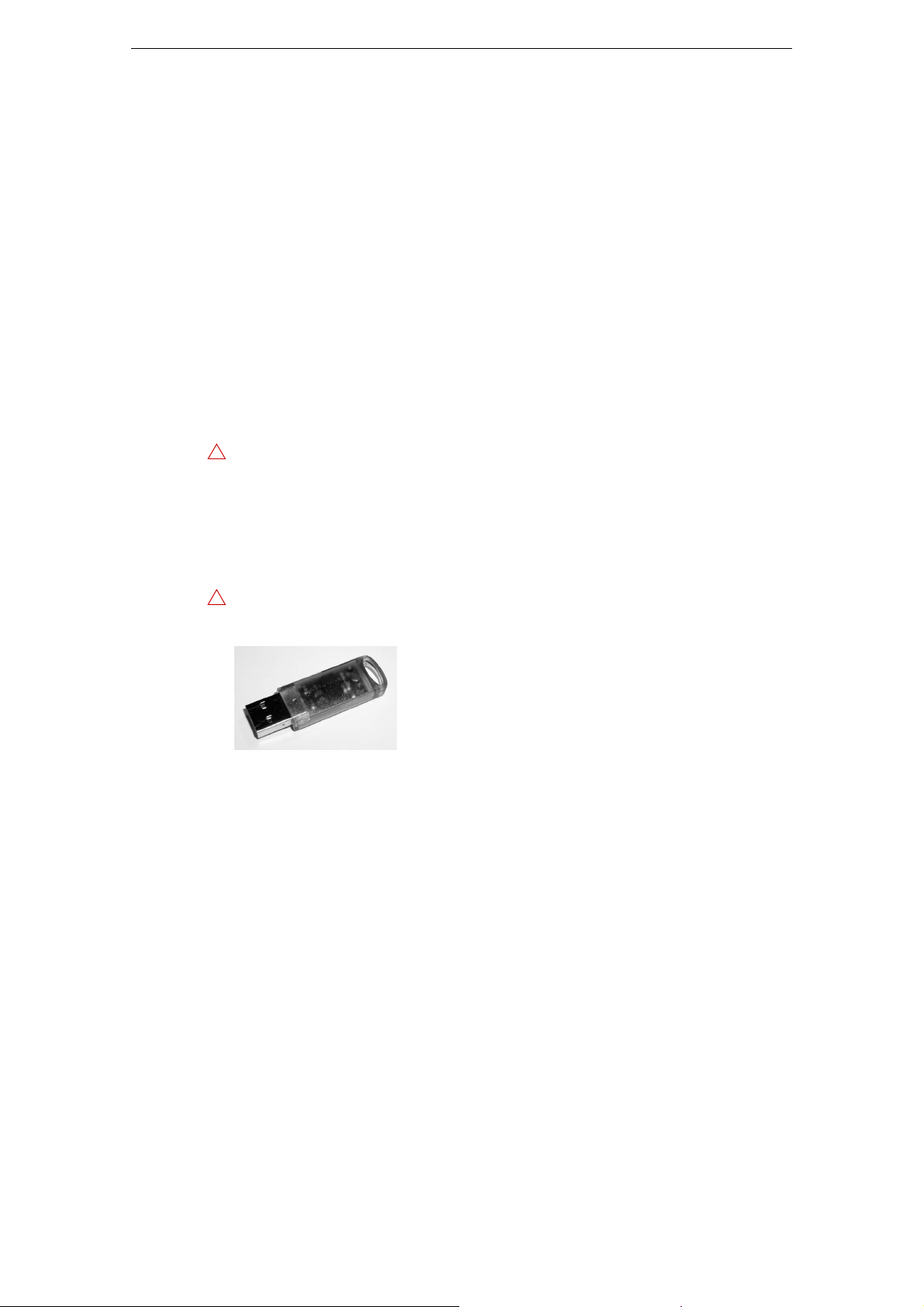
The USB-eLicenser
Many Steinberg products, including HALion Sonic, use the USB-eLicenser, a
hardware copy protection device. HALion Sonic will not run without an eLicenser
containing an activated license.
The USB-eLicenser is a separate product and is not included in the product package
of HALion Sonic.
The USB-eLicenser is a USB device on which your Steinberg software licenses are
stored. All hardware-protected Steinberg products use the same type of device, and
you can store more than one license on one device. Also, licenses can (within certain
limits) be transferred between USB-eLicensers. This is helpful if you want to sell a
piece of software, for example.
The product package of HALion Sonic contains an activation code, which is found on
the Essential Product License Information card within the product package. To make
unlimited use of your version of HALion Sonic, you must manually download a license
to an USB-eLicenser connected to your computer, and activate your permanent
license using the activation code.
In the eLicenser Control Center you can activate new licenses and check which
licenses are installed on your USB-eLicenser. After installation of HALion Sonic, the
eLicenser Control Center can be opened via the Start menu on Windows systems or
the Applications folder on a Mac.
Ö If you are using other copy-protected Steinberg products, you may want to transfer all
licenses for your applications to one USB-eLicenser, thus using up only one USB port
of your computer. Please refer to the eLicenser Control Center Help for information on
how to transfer licenses between USB-eLicensers.
7
Installation and setup
Page 8
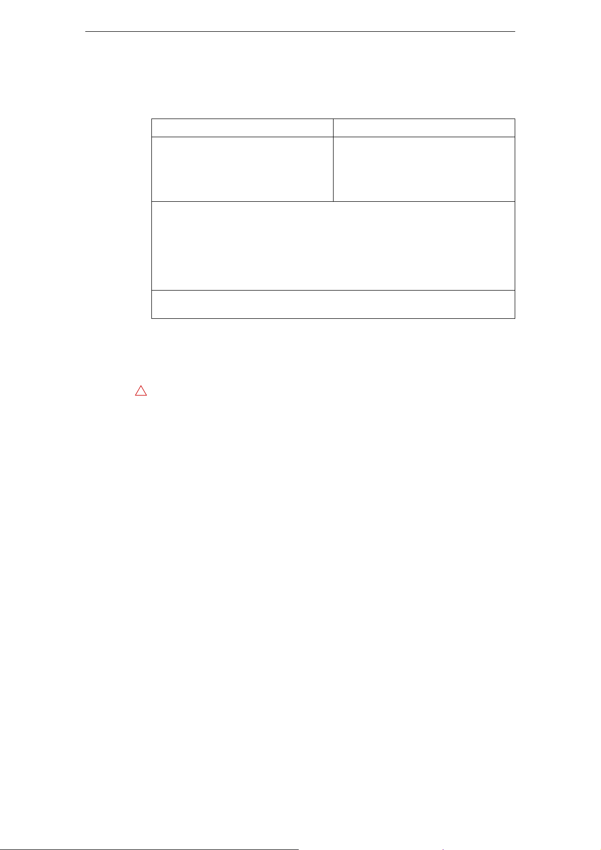
System Requirements
!
Your computer must meet the following minimum requirements for the Windows and
Mac versions of HALion Sonic:
Mac OS X Windows
Mac OS X Version 10.7/10.8*
Intel dual-core processor
CoreAudio-compatible audio hardware
VST 3 or AU-compatible host application
for using HALion Sonic as a plug-in
Internet connection required for installation, activation, account setup, and
**ASIO compatible audio hardware recommended for low-latency performance.
Installation
Windows 7/Windows 8*
Intel or AMD dual-core processor
Windows-compatible audio hardware**
VST 3 or VST 2-compatible host application for using HALion Sonic as a plug-in
4 GB RAM
17 GB of free hard-disk space
Display resolution of 1280 x 800 pixels recommended
DVD ROM dual-layer drive required for installation
USB port for USB-eLicenser (license management)
personal/product registration.
*Native 32-bit and 64-bit program version.
Installing HALion Sonic
HALion Sonic provides a large amount of content and is distributed on a set of two
DVDs. Please have all DVDs ready for the installation.
The HALion Sonic installer allows you to save the content files on a different hard
drive than the program files.
Proceed as follows:
1. Insert the first DVD into your DVD drive.
An interactive Start Center appears. If it is does not open automatically or if you
have a Macintosh computer, you can manually open it by double-clicking the file
“HALion_Sonic_Start_Center.exe” (Windows) or “HALion Sonic Start Center.app”
(
Mac).
2. Follow the instructions on screen to start the installation of HALion Sonic and
browse through the additional options and information presented.
If you do not want to install HALion Sonic via the interactive Start Center, follow the
instructions below:
Windows
1. Double-click the file called “Setup.exe”.
2. Follow the instructions on screen.
Macintosh
1. Double-click the file called “HALion Sonic.mpkg”.
2. Follow the instructions on screen.
8
Installation and setup
Page 9

Register Your Software
We encourage you to register your software! By doing so you are entitled to technical
support and kept aware of updates and other news regarding HALion Sonic.
• To register HALion Sonic, click the Steinberg logo in the top right corner of the
control panel and select “Register HALion Sonic now!” from the pop-up menu.
This option opens the registration page of the Steinberg web site in your web
browser. To register, follow the instructions on screen.
Setting Up
The following sections describe how to use HALion Sonic as a plug-in in different
host applications, or as a standalone instrument.
Setting Up HALion Sonic as a VST Instrument in Cubase
We assume that you have correctly set up Cubase as well as your MIDI and audio
hardware, and that Cubase receives MIDI data from your external MIDI keyboard. If
you want to use HALion Sonic in another VST host application, please refer to the
documentation of the corresponding application.
Cubase provides two ways of working with VST instruments: the VST Instruments
window and instrument tracks.
Setting Up
Accessing HALion Sonic via the VST Instruments Window
Proceed as follows:
1. Open the Devices menu in Cubase and select the VST Instruments option.
The VST Instruments window opens.
2. Click one of the empty slots to open the instrument pop-up menu, and select
HALion Sonic.
You are asked whether you want to create an associated MIDI track connected to
the VST instrument.
3. Click Create.
HALion Sonic is loaded and activated, and its control panel opens. A MIDI track called
HALion Sonic is added to the track list. The output of this track is routed to HALion
Sonic.
Accessing HALion Sonic via an Instrument Track
Proceed as follows:
1. On the Project menu, open the Add Track submenu, and select “Instrument”.
The Add Instrument Track dialog opens.
2. On the instrument pop-up menu, select HALion Sonic.
3. Click OK to create the instrument track.
4. Click the Edit Instrument button in the Cubase Inspector to open the HALion
Sonic control panel.
HALion Sonic is now set up as a VST instrument in Cubase. For more details about
the handling of VST instruments, see the Cubase Operation Manual.
9
Installation and setup
Page 10

Selecting Outputs
HALion Sonic loads with a stereo output configuration by default. However, you can
use up to 15 additional outputs in Cubase. This allows you to route all 16 program
slots to a dedicated Cubase Mixer channel.
To make these outputs available, proceed as follows:
1. Open the VST Instruments window.
2. Click the output button for the HALion Sonic instrument.
3. Activate the required outputs.
Cubase automatically creates a MIDI track for each additional output and adds a
channel to its Mixer. You can now route HALion Sonic programs, layers, or drum
instruments (slices) to these outputs for further signal processing within Cubase.
Using HALion Sonic in an AU Compatible Application
You can use HALion Sonic in an AU host application (e. g. Logic). The AU version of
HALion Sonic is installed in your AU plug-ins folder and lets HALion Sonic work in an
AU environment without any performance loss or incompatibilities.
For Logic Pro, proceed as follows:
1. Open the Track Mixer and select the instrument channel that you want to use.
2. Click in the I/O field, and open the AU Instruments submenu.
Setting Up
3. On the Steinberg submenu, open the HALion Sonic submenu and select one of
the available channel configurations.
HALion Sonic is now loaded as an AU instrument.
HALion Sonic Standalone
HALion Sonic can be used as a standalone application, independently of any host
application. In this case, you can connect HALion Sonic directly to your audio
hardware. The controls specific to the standalone application are described in the
section
“The Controls in the Standalone Functions Section” on page 187.
10
Installation and setup
Page 11
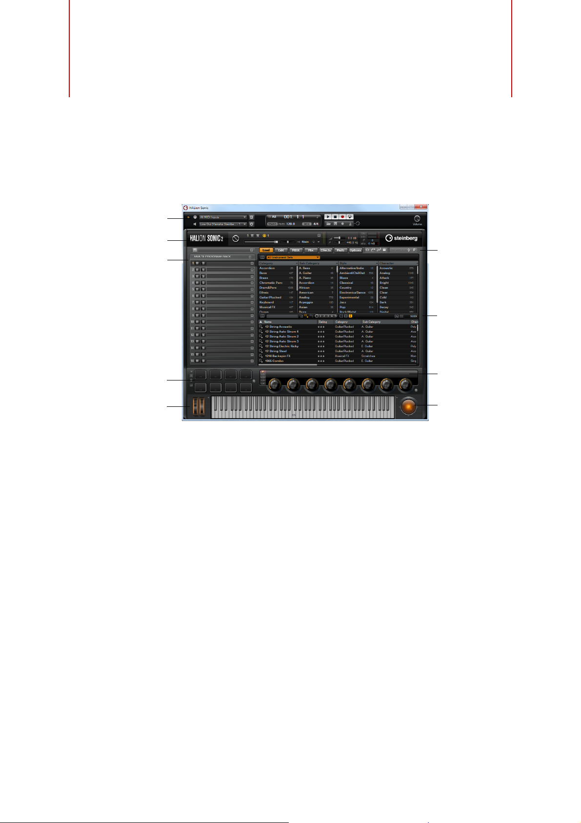
HALion Sonic Overview
Performance
controllers
Plug-in functions
Standalone functions
Multi Program Rack
Toolbars
Trigger pads
Sphere
Edit display
Quick
controls
Introduction
The HALion Sonic interface follows a fixed size single-window concept and is
subdivided into several sections:
• The Multi Program Rack on the left.
See “The Multi Program Rack” on page 15.
• The Edit display with the Load, Edit, MIDI, Mix, Effects, Multi, and Options pages
on the right.
See the chapter “Editing” on page 25.
• The Performance section with the trigger pads, quick controls, performance
controllers, and sphere control at the bottom of the application window.
See “The Performance Section” on page 166.
• The Plug-in functions section at the top of the application window.
See “The Plug-in Functions Section” on page 179.
• The toolbars above the Edit display.
See “The Toolbars” on page 181.
• If you are using the standalone version of HALion Sonic, you will find a number of
specific functions in an extra section at the top of the application window.
See “The Controls in the Standalone Functions Section” on page 187.
11
Page 12
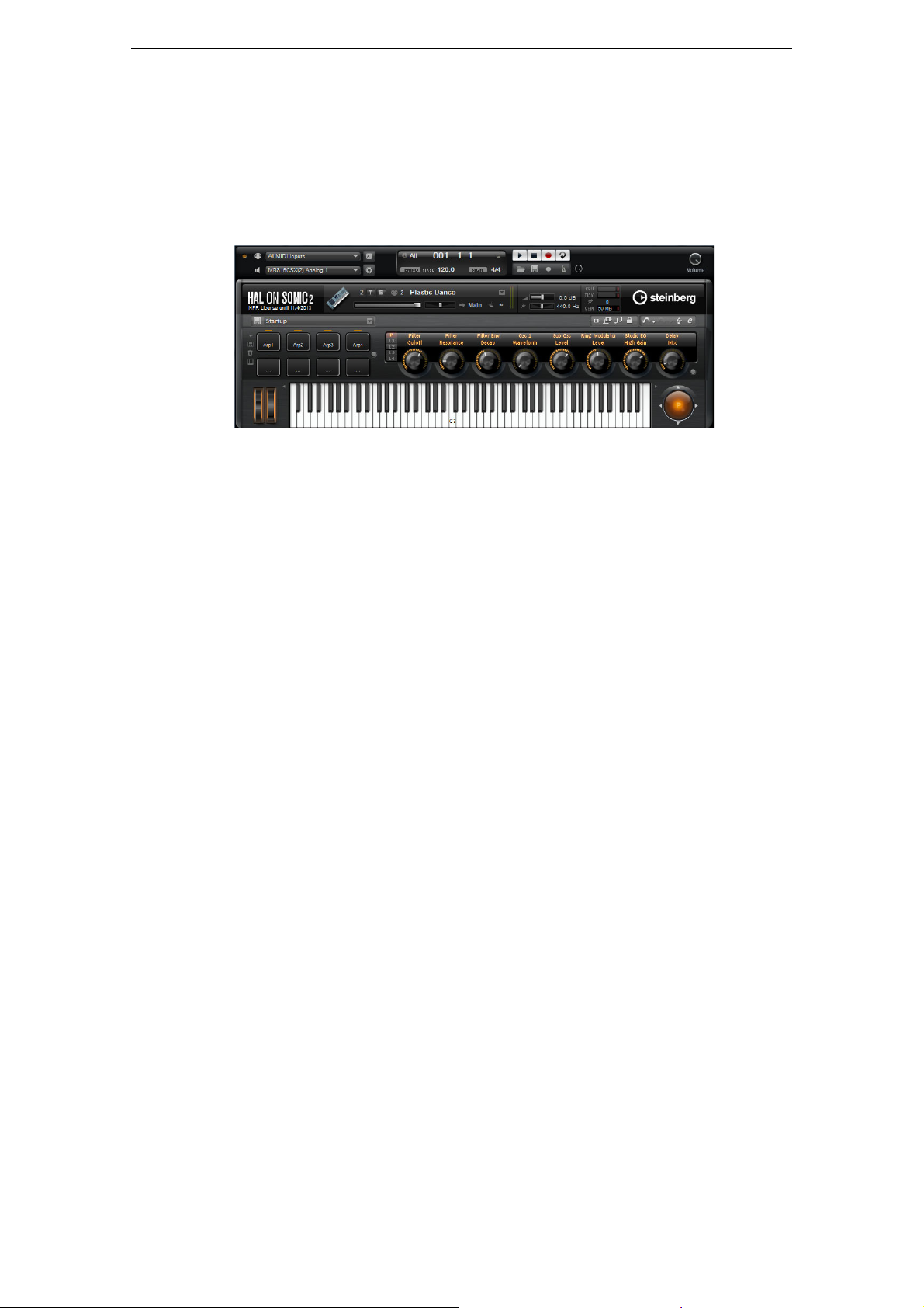
Player view
About Programs, Layers, Multis, Macro Pages, and Presets
HALion Sonic provides two view options: the full-size editor view and the smaller
player view.
• Click the “p” button in the small toolbar below the Steinberg logo to switch to the
player view. In the player view, only the plug-in functions, trigger pads, Quick
Controls, and the performance controllers are visible.
The button now reads “e” – clicking it restores the editor view.
Integrated in HALion Sonic is the MediaBay, a feature of many Steinberg products.
The MediaBay allows you to find and manage all sounds quickly. The MediaBay are
available on the Load page and in the Load dialogs for layers, programs and multis,
see
“Managing Files via the MediaBay” on page 19.
When opening HALion Sonic for the first time, a program with several layers is already
loaded. You can use a MIDI keyboard connected to your computer or the HALion
Sonic on-screen keyboard to play a few notes, and explore the different pages of the
Edit display.
About Programs, Layers, Multis, Macro Pages, and Presets
Programs
A HALion Sonic program is a complex instrument or sound that combines up to four
so-called layers. Often, a program contains a single layer that already comes with all
necessary components such as the synthesis part or insert effects. This is because a
layer already is a complete sound structure on its own, see below. The program adds
the possibility of combining different layers to build up even more complex sounds or
to create combinations of sounds you want to load as a unit. A typical example would
be a bass/piano split sound or a piano/string layer sound.
Because of the various layer types that come with HALion Sonic, these combinations
can do a lot more. For example, think of combining a pulsating synthesizer sequence
with a sliced loop completed by a bass on the lower keys and so on. Finally add some
effects to individual layers or to the whole program and you will get a unique sound
experience. You will find that the options are endless.
Multis
HALion Sonic is a multitimbral plug-in that can load up to 16 sounds (or programs),
and combine them. This combination is called a “multi program”, or multi for short. You
can use multis, for example, to layer several programs or to create split sounds by
setting several programs to the same MIDI input channel. However, the most common
usage is to create sound sets with different instruments set to individual MIDI channels.
12
Introduction
Page 13

Layers
About Programs, Layers, Multis, Macro Pages, and Presets
Programs are combinations of up to four layers. HALion Sonic provides five different
layer types. You can choose between synth, sample, instrument, drums, and sliced
loop layers. Each layer type is based on an individual sound architecture and has a
dedicated editor.
Synth and Sample Layers
For synth and sample layers, you get access to a synthesizer editor with components
such as a highly flexible filter section, powerful multi-stage envelopes, LFOs, a step
modulator, and a modulation matrix. These layer types differ in their basic sound
source. While a synth layer provides an oscillator section with three main oscillators,
namely a sub oscillator, a noise generator, and a ring modulation stage, the sample
layer loads a specific multi-sample instead.
Drum Layers
The drum layers load a multi-sampled drum set, where you can individually adjust the
most important parameters for each drum instrument. Each drum instrument can be
set to a specific pan position or an individual output, or it can be filtered, reversed, and
so on.
Loop Layers
Loop layers load a sliced loop, which is a combination of a loop-specific MIDI phrase
and the individual slices mapped across the keyboard. You can either play the original
loop, a transposed version of it, or trigger single slices manually. Each slice can be
modified with the same parameters as the drum instruments.
Instrument Layers
Instrument layers contain several multi-samples of an instrument that can be parts of
single sounds or different articulations. These sublayers are called “expressions”. You
can modify expression parameters. By switching off an expression, you can shorten
the load time of a sound.
Presets
You can save and load all types of sounds as presets, i. e., there can be multi,
program, and layer presets.
Content Files and Folder Structure
HALion Sonic is supplied with a huge amount of ready-to-use sound content. This
content, made up of hundreds of multis, programs, and layers, is write-protected. This
means that you can edit files while they are loaded in HALion Sonic, but you cannot
overwrite the factory content files themselves to make your changes permanent.
To save any edits to the factory content, you must save the files under a new name
and to a predefined location. These files have the name extension “.vstpreset”, and are
referred to as “user content”. You can categorize and search for them in the same way
as with the factory content.
The user content is saved in a predefined folder structure on your hard disk (the exact
path depends on your operating system), but you can create subfolders within this
structure, to facilitate moving or exchanging content (see
User-Defined Multis” on page 18).
“Creating Subfolders for
13
Introduction
Page 14

VST Sound Instrument Sets and Macro Pages
VST Sound Instrument Sets from Steinberg provide additional content for VST
instruments based on the HALion technology. They come with their own Edit pages,
called Macro pages, that feature a customized look and a collection of controls that
match the functions of the VST Sound Instrument Set. When you edit a program or
layer of a certain VST Sound Instrument Set, the accompanying Macro page opens.
For details on the functions and controls of a particular Macro page, please read the
documentation that comes with the corresponding VST Sound Instrument Set.
Missing Content
There may be situations in which a content file becomes unavailable. The reason can
be a closed encrypted partition or a detached removable hard drive, for example. In
these cases, you will be prompted that a specific VST Sound Library cannot be found.
To access the content again, proceed as follows:
1. Click Ignore.
2. Quit HALion Sonic.
3. Reattach the removable hard drive or reopen the encrypted partition.
About Programs, Layers, Multis, Macro Pages, and Presets
HALion Sonic is loaded, containing the content that could be found.
4. Launch HALion Sonic.
If content files are missing for another reason (e. g. if you moved them onto another
hard drive after installation, or if you have added a hard drive, thereby “shifting” the
partitions), proceed as follows:
1. In the window with the message regarding the missing VST Sound Library, click
Locate.
file dialog opens, allowing you to choose a different file location.
2. Browse to the directory where the content is located.
3. Select the file and click Open.
All content files in this location become available.
• Click Remove if you do not want HALion Sonic to search for a particular file in the
future.
Ö You can activate the “Do not ask again” option if you want to ignore or remove all
missing files at once.
14
Introduction
Page 15
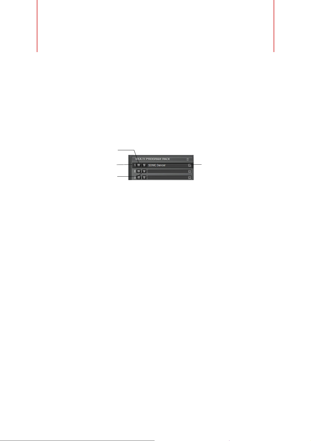
Introduction
Load Program
Mute slot
Solo slot
MIDI activity
indicator
This chapter describes the basic functions of the Multi Program Rack and how to
manage sounds with it. Furthermore, the Load page with the MediaBay is explained,
and how to set up a multi chain via the Multi page.
The Multi Program Rack
Managing Your Sounds
The Multi Program Rack provides 16 slots, so that you can load up to 16 programs
simultaneously. This is where you load programs, and create and manage your multi
programs.
The Multi Program Rack is linked to the various pages of the Edit display: When the
Edit page is open and you click individual slots in the Multi Program Rack, you can see
the settings for each loaded program (see
parameters such as level, pan, MIDI channel, etc. can be found on the MIDI and Mix
pages (see
There are several ways to load programs and layers into the Multi Program Rack:
• You can load programs and layers directly via the Multi Program Rack (see
“Managing Programs via the Slot Context Menu” on page 16).
• On the Load page, you can use the HALion Sonic MediaBay to load programs and
layers (see
• You can use the program slot in the plug-in functions section to load a program
(see
Loading Programs
Programs and layers can be dragged from the following locations to the Multi Program
Rack:
- MediaBay of HALion, HALion Sonic or a Steinberg DAW
- Explorer (Win) or Finder (Mac)
Alternatively you can use the “Load Program” button at the right of the slot to load a
new program. The following applies:
Ö Programs containing lots of sample data may take some time to load.
“Editing” on page 25). Additional slot
“The MIDI Page” on page 128 and “The Mix Page” on page 129).
“Managing Files via the MediaBay” on page 19).
“The Plug-in Functions Section” on page 179).
Ö When you click in an empty slot, the Load Program window is automatically opened.
Replacing Programs
You can replace the program in a slot by dragging another program or layer onto this
slot.
15
Page 16

Loading Layers into Slots
If you load a layer into a slot, HALion Sonic creates a new program.
Managing Programs via the Slot Context Menu
The slot context menu provides additional functions for managing programs. The
following options are available:
Option Description
Load Programs This option opens the “Load Program” dialog. Double-click a
program or layer to load it into this slot.
Save Program This option saves the program. Please note that factory content
cannot be overwritten. Instead, the “Save Program” dialog is
opened and you can save the edited program under a new name.
Save Program As… This option opens the “Save Program” dialog where you can
save the edited program under a new name.
Save All Programs… This option opens the “Save Programs” dialog where you can
save all programs as VST preset.
Remove Program Select this option to remove the program from the slot.
Init Program Select this option to load the Init program. This contains a neutral
synth layer.
Revert to Last Saved
Program
Cut Program Select this option to copy the program and remove it from the
Copy Program Select this option to copy the program without removing it.
Paste Program Select this option to paste the copied program into the slot. If the
Rename Program Select this option to enter a new name.
Reset Slot Select this option to reset the slot to the default values.
Reset All Slots Select this option to reset all slots to the default values.
Select this option to discard any changes made to the program
in the slot.
slot.
slot already contains a program, it is replaced.
The Multi Program Rack
Ö You can also cut, copy, and paste programs from one instance of HALion Sonic to
another.
Renaming Programs
You can rename a program via the context menu.
Ö To make the program with its new name available in the MediaBay, you must save it.
Slot Controls
MIDI Activity Indicator
The slot number not only serves as a label but also indicates incoming MIDI data by
lighting up.
Solo
Activate the Solo button of a slot in order to hear only the corresponding program.
Several slots can be soloed at the same time.
Mute
Activate the Mute button to turn off playback of the program.
16
Managing Your Sounds
Page 17

Managing Multis
Save Multi-Program Remove Multi-Program
Load Multi-Program
Multis can load multiple sounds or programs and combine them. You can use multis,
for example, to layer several programs or to create split sounds by setting several
programs to the same MIDI input channel. However, the most common usage is to
create sound sets with different instruments set to individual MIDI channels.
A multi-program contains all plug-in parameters. When using HALion Sonic as a plugin in Cubase or Nuendo, these multis are listed in the Preset Management pop-up
menu of the host application. You can drag multis and programs from the Cubase or
Nuendo MediaBay to a slot in HALion Sonic.
When using HALion Sonic as a plug-in in a different host application, you can use
either the preset functionality from the host application, or the multi management
features provided by HALion Sonic.
Loading Multis
Managing Multis
• Open the Load page to show the MediaBay and double-click a multi, or drag and
drop a multi onto the multi slot.
• Click the “Load Multi-Program” button in the multi slot to open the “Load Multi-
Program” dialog, and double-click a multi or select it and click OK.
Loading Multis in a Host Application
When using HALion Sonic as a plug-in in Cubase or Nuendo, you will find the multis
listed on the Preset Management pop-up menu of the host application. You can drag
multis and programs from the Cubase or Nuendo MediaBay to a slot in HALion Sonic.
When using HALion Sonic as a plug-in in a different host application, you can use
either the host’s preset functionality, or the multi management features provided by
HALion Sonic.
Removing Multis
• To remove all programs of the current multi, click the “Remove All Programs”
button on the toolbar of the Slot Rack.
This also resets all slot parameters. However, AUX and Master effects are not
removed.
Clearing the Plug-in Instance
To reset the entire HALion Sonic instance to an empty state, right-click the Multi
Loader and select “Clear Plug-in Instance” from the context menu.
17
Managing Your Sounds
Page 18
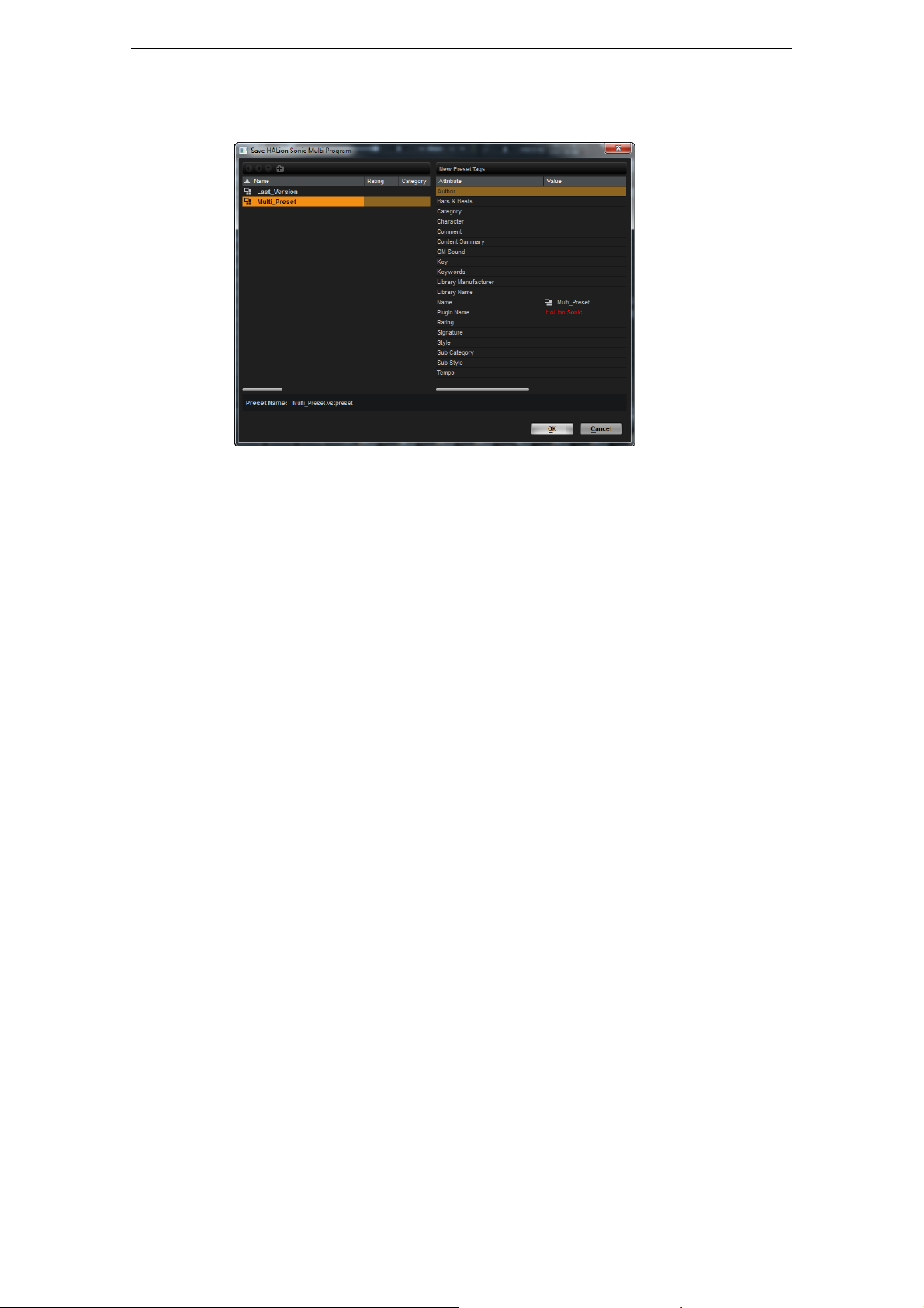
Saving Multis
Managing Multis
To save a multi, proceed as follows:
1. Click the “Save Multi-Program” button.
2. Enter the name of the multi.
3. Assign any attributes you require and click OK.
If the entered name already exists, the “Make Unique Name” option adds a number
suffix to the name of the new multi.
If you enter a name that already exists in this location, a dialog opens asking you if you
want to overwrite the existing file. If not, click Cancel to modify the name before
saving, or click “Make Unique Name” to add a number suffix (-01,-02, …) to the new
multi’s name.
Saving a Multi as Default
To specify a default multi to be loaded with each new HALion Sonic instance, rightclick the Multi Loader and select “Save as Default” from the context menu.
Creating Subfolders for User-Defined Multis
You can create subfolders inside the user preset folder to organize presets.
• To create a new folder, click the “Create New Folder” icon at the top left of the
“Save Multi-Program” dialog.
Navigating Through the Folder Hierarchy
You can move through the folder hierarchy using the three navigation buttons at the
top left of the dialog.
They allow you to navigate to the previous or next browse location, or browse the
containing folder.
Editing Attributes
In the “New Preset Tags” section on the right of the “Save Multi-Program” dialog you
can edit the attribute values that are assigned to the preset.
1. To edit an attribute, click on a value field, and enter the new name or value.
2. Click OK to save the preset.
For further information about attributes, see “Editing Preset Attributes” on page 22.
18
Managing Your Sounds
Page 19
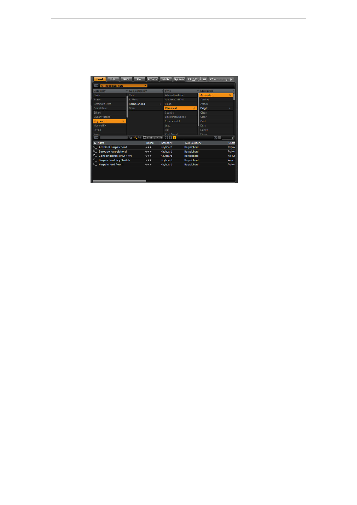
Managing Files via the MediaBay
On the Load page in the Edit display, you will find the MediaBay. It gives you access
to all HALion Sonic presets such as multis, programs, and layers.
Managing Files via the MediaBay
The Load page with the integrated MediaBay is divided into two sections. In the top
section you can define which kind of sounds you want to look for. The lower section
presents the corresponding results list. You can drag the divider at the top of the
results list to adjust the size of the two sections.
Loading Programs Into Slots
To load a program into one of the slots of the Multi Program Rack, you have the
following possibilities:
• Select the slot into which you want to load the program and double-click the
program in the results list.
• Drag the program from the results list and drop it to a slot.
• Right-click the program and select “Load Program into selected Slot” from the
context menu.
Ö When you reopen the Load Program window via a slot that already has a program
loaded into it, the Category and Sub Category filters will automatically be set to match
those of the current program. This makes it easy to exchange sounds with similar
ones, without having to readjust the search filter settings. Of course, you can still
modify your search or reset it completely to see all available programs.
Importing Presets
You can import existing program presets from any file location using the Explorer
(Win) or Finder (Mac). To import presets, proceed as follows:
1. Select the preset in the Explorer/Finder.
2. Drag it to the MediaBay.
The imported presets are copied to your user folder.
Deleting Presets
• To delete a user preset, right-click it and select “Delete”.
Factory presets cannot be deleted.
19
Managing Your Sounds
Page 20
Applying Filters
Multi
Program
Layer
Category Filter
You can filter the results list based on up to four filter criteria using the configurable
attribute columns.
Standard attributes are Category, Sub Category, Style, and Character. By clicking on
specific values in the columns, you define the filter. Only the files that match the
selected values are displayed in the results list. Select more values from other
columns to refine the filter.
• To select different filter criteria, click the column header, and select a different
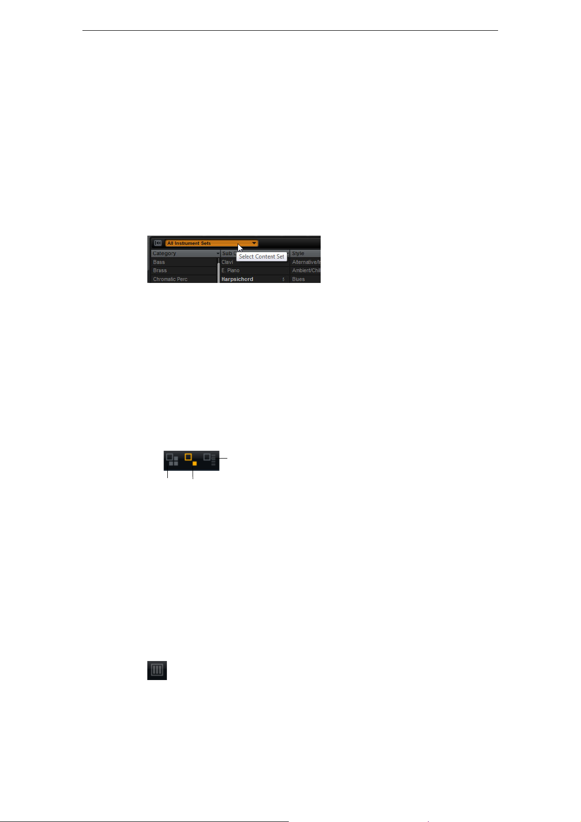
Instrument Set Filter
To select a particular instrument set for your search, proceed as follows:
1. Click in the Instrument Set field at the top of the MediaBay section to open the
Managing Files via the MediaBay
attribute from the submenu.
Instrument Set selector.
All installed instrument sets are listed.
2. Select an instrument set.
• To search sounds across all installed instrument sets, select “All Instrument Sets”.
Using the Results List
The results list shows all files that have been found according to the category filter.
View Filters
The toolbar of the results list has three filter buttons to define which preset types are
displayed. Presets can be multis, programs, and layers. To show a preset, activate the
corresponding icon. In the results list, the corresponding icon is shown to the left of
the preset name.
Columns
The columns of the results list show all the attribute values for the presets that match
the filters that you set up in the top section.
You can reorder the columns in the results list by dragging the table headers to
another position. Furthermore, you can use the column headers to change the sorting
of the list entries. The triangle in the column header shows the sorting direction.
Setting Up the Result Columns
You can select which attribute columns are displayed, by clicking the “Set up Result
Columns” button on the toolbar of the results list. The attributes that you choose are
added at the right of the list.
20
Managing Your Sounds
Page 21
Managing Files via the MediaBay
Rating Filter
You can limit the results list to presets that have a certain rating. The rating slider
allows you to define the minimum rating.
Text Search
In the text search field on the results list toolbar you can enter text contained in the
name or any of the attributes of a preset that you are looking for. The results list
updates immediately and the Category search section above shows all categories
that contain presets matching the text search.
Resetting the Result Filter
• To reset the text-based result filter, click the Reset button to the left of the search
field.
Content Filter
The content filter buttons allow you to define whether you want to see all presets, only
the factory presets, or only your user presets.
The Results Counter
The number of presets that match the filter criteria is displayed at the far right of the
results list toolbar.
Using the Context Menu of the Results List
The context menu of the results list offers additional options for managing the
selected presets. The following options are available for factory and user presets:
Options Description
Load Program into
selected Slots/
Load Multi-Program
Select All This selects all presets in the results list.
Select None This cancels any selection.
This loads the highlighted preset.
The following options are available for user presets only:
Options Description
Copy This copies the selected presets to the clipboard. This way,
you can paste them at a different location using the file
browser of your OS.
Rename This opens a dialog for renaming the highlighted preset.
Delete This moves the selected presets to the trash bin of your
operating system.
21
Managing Your Sounds
Page 22

Options Description
!
Show in Explorer/ Reveal in
Finder
Set or remove Write
Protection
Programs from the HALion Sonic factory content are write-protected and cannot be
deleted or renamed.
Editing Preset Attributes
Each preset can be described using a predefined set of attributes. These attributes
can be set directly in the results list or in the section “New Preset Attributes” of the
Save dialog.
1. Click in the field of the attribute value that you want to set.
Depending on the attribute, a menu or a dialog opens.
2. Select a value.
Ö Attribute values are written directly into the corresponding preset files. However, this
is not possible for write protected factory content. In this case, the data is saved
within HALion Sonic’s MediaBay database.
Managing Files via the MediaBay
This shows the preset in the file browser of your operating
system.
This sets or removes the write protection for the selected
presets.
Attributes
Attribute values can be set directly in the results list or the Save dialog. The following
table shows how to edit the various attribute values:
Attribute type Attribute Editing method
Media
Name Display only.
Rating Drag to set the rating.
Comment Click to select, double-click to edit.
Content Summary Click to select, double-click to edit.
Write Protection Display only, use context menu to set
protection.
Library Name Click to select, double-click to edit.
Library Manufacturer Click to select, double-click to edit.
Author Click to select, double-click to edit.
Musical
Category Click to select.
Sub Category Click to select.
Style Click to select.
Sub Style Click to select.
Character Click to open an editor dialog.
Tempo Click to select, double-click to edit.
Bars & Beats Click to select, double-click to edit.
Signature Click to select, double-click to edit.
Key Click to select.
GM Sound Click to select.
22
Managing Your Sounds
Page 23
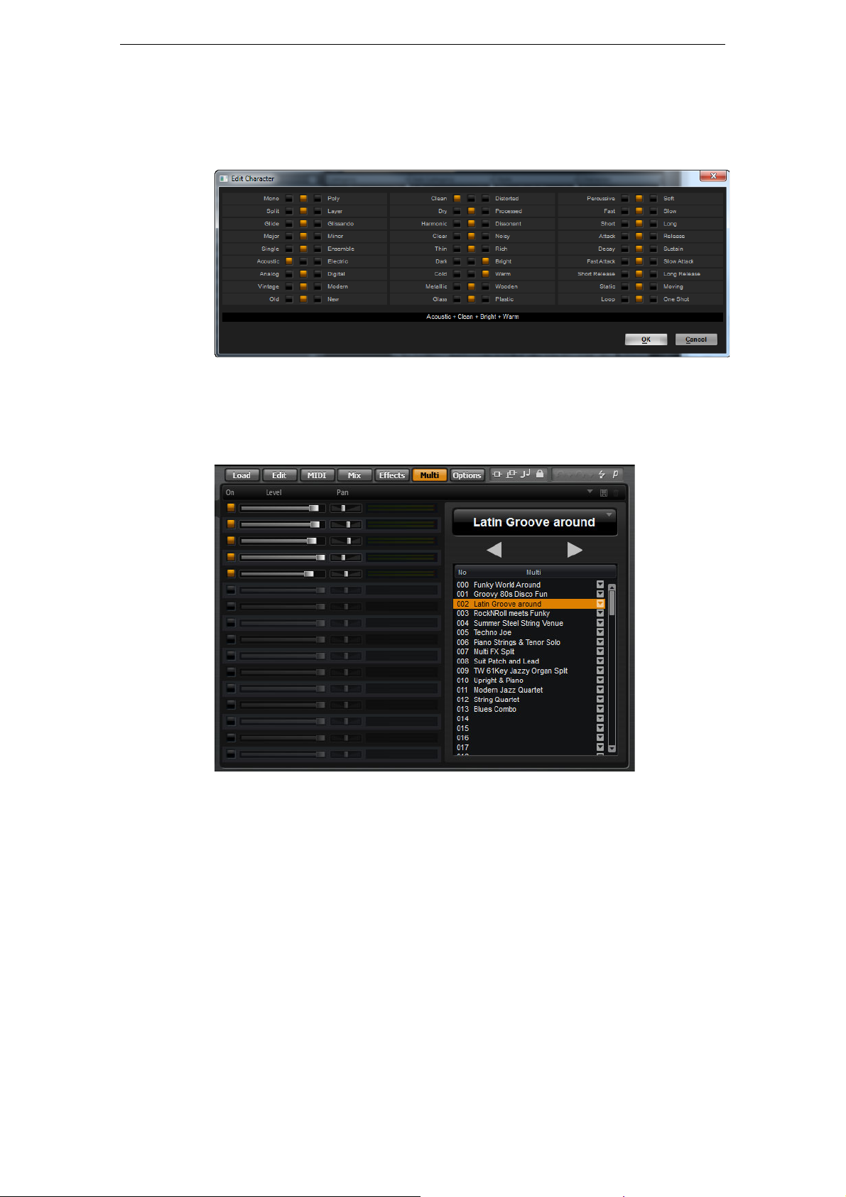
Setting the Character Values
Character attribute values can be set via a dedicated editor. This editor provides a list
of values that describe the character of a sound.
Setting Up a Multi Chain
HALion Sonic comes with a special multi chain feature which allows you to set up a
list of 128 multis. This is done on the Multi page of the Edit display.
Setting Up a Multi Chain
The list of multis in your chain is displayed on the right. When you select a multi in this
list, its name is displayed in the field above the list, and the corresponding programs
are displayed in the list on the left.
You can step through the multis manually or via MIDI control changes. This feature is
particularly useful when performing live on stage. It allows you to set up a list of
sounds that follows the order of their appearance during your performance, for
example.
• To load an existing multi chain, use the preset controls in the top right corner of the
Multi page.
To set up a multi chain, proceed as follows:
1. Open the Multi page, and in the list on the right, click the down arrow button of a
list entry to open the Load Multi-Program dialog.
2. Select a multi and click OK.
3. Repeat the same procedure for all multis that you want to be part of the list.
23
Managing Your Sounds
Page 24

Setting Up a Multi Chain
You can now step through the list by clicking the left (Load Previous Multi) and right
(Load Next Multi) arrow buttons, or select a particular list entry with the mouse to load
the corresponding multi. In addition, you can also assign arbitrary MIDI controllers to
remotely control the Previous and Next buttons with a hardware controller (see
“Assigning MIDI Controllers to the Previous/Next Buttons” on page 24).
Changing the Order of the Chain
You can rearrange the order of the chain by dragging an entry to a new position in the
list.
Clearing the Chain
To remove all entries from the multi chain list, proceed as follows:
1. Click the down arrow button in the name display.
2. Select “Clear Multi Chain”.
Removing a Multi From the Chain
To remove a single multi from the multi chain list, proceed as follows:
1. Click the down arrow button in the name display.
2. Select “Remove Selected Multi”.
Assigning MIDI Controllers to the Previous/Next Buttons
For switching through the multi chain, you can also use MIDI controllers, such as a
knob, a fader or the modulation wheel. To enable this function, you have to assign the
controller first.
1. Right-click the Load Previous Multi or the Load Next Multi button.
2. From the context menu, select “Learn CC”.
3. On your hardware controller, use a control of your choice.
Repeat the steps above for the other button.
You can use either the same MIDI controller for both Load Previous Multi and Load
Next Multi, or one controller for Previous and another controller for Next.
The following applies:
• When the same MIDI controller is assigned to both buttons, the Load Next Multi
command is triggered by the transition from the center position to the upper range
of the control, and the Load Previous Multi command by the transition from the
center position to the lower range of the control.
• When you are using two different MIDI controllers, any transition from the lower to
the upper range of the respective control will trigger the Load Previous Multi
command or the Load Next Multi command.
• To remove an assigned MIDI controller, right-click the button and select “Forget
CC”.
Switchching Multis Using Control Change Messages
If “Multi Mode” is selected on the Program Change pop-up menu on the Options
page, you can use Program Change messages to switch between the multis.
24
Managing Your Sounds
Page 25
Introduction
All editing of programs and layers is done via the Edit page of the Edit display. The
Edit display is a multipurpose display that shows various editor views depending on
the selected page and slot. Seven different editors can be opened with the “Show
page” buttons above the Edit display. These pages are the Load (see
via the MediaBay” on page 19), Edit (see below), MIDI (see “The MIDI Page” on page
128), Mix (see “The Mix Page” on page 129), Effects (see “Global Effects” on page
131), Multi (see “Setting Up a Multi Chain” on page 23) and the Options page (see
“The Options Page” on page 182).
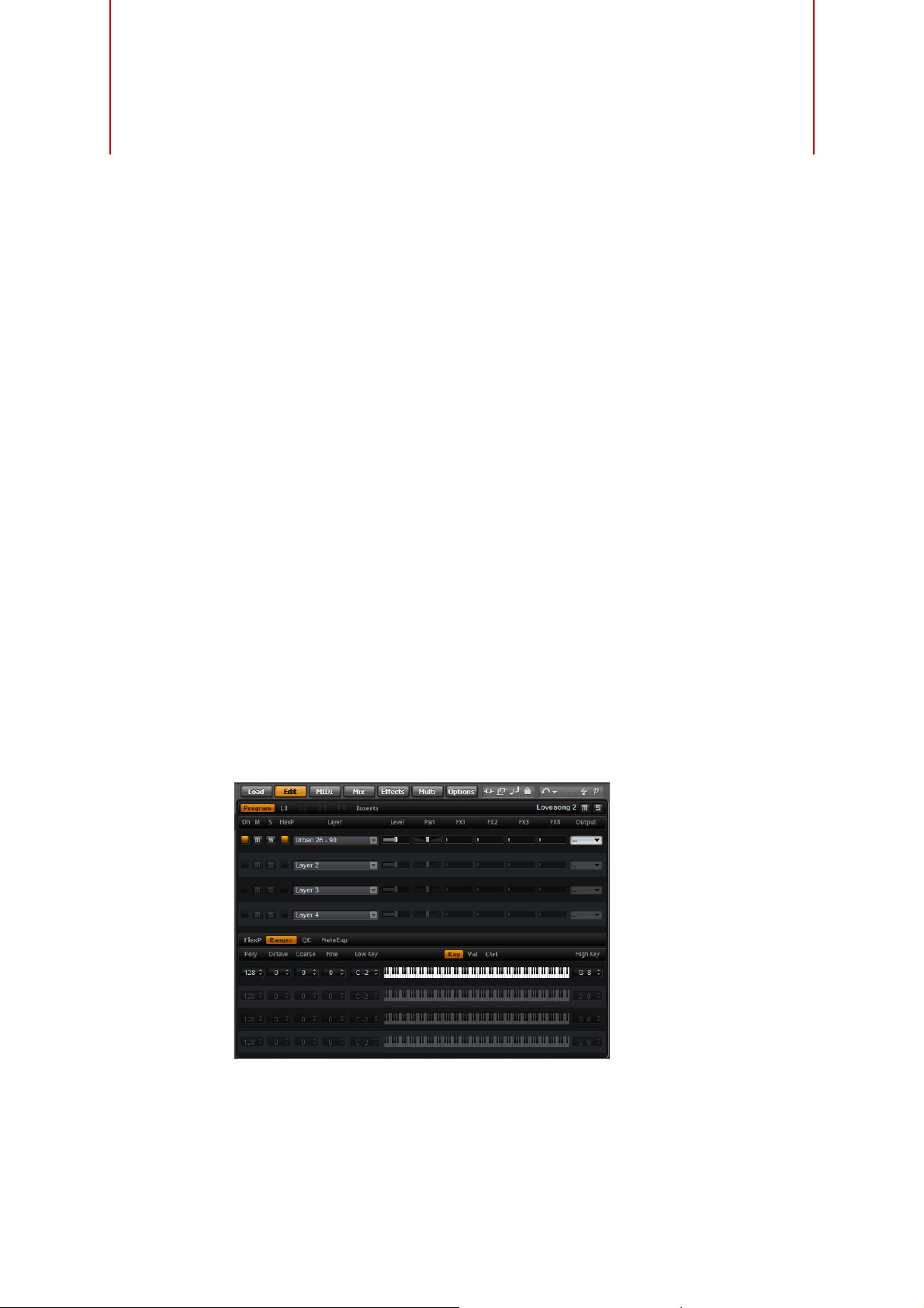
Editing Programs
The Edit page is where you edit your program, load different layers for a program, and
edit the layers. A program contains up to four layers which can all be mapped to
different velocity and key ranges. Each of the layers can use a dedicated FlexPhraser
and can be routed freely to one of the 16 plug-in outputs. HALion Sonic also provides
four insert effects per layer and allows you to use up to four sends to feed the four
auxiliary busses.
To edit a program, proceed as follows:
Editing
“Managing Files
1. Select the program you want to edit in the Multi Program Rack.
2. Click Edit to open the Edit page.
3. Click the Program button at the top of the Edit page.
The Program subpage is shown on the Edit page.
The Program page is divided into two sections. The section at the top is used to load
and save layers, and to set up the mix parameters such as level, pan and FX sends.
The bottom section is used to display layer ranges, program FlexPhraser editors, quick
control assignments or Note Expression parameters.
25
Page 26

The Program Page
The top section of the Program page serves for loading and setting up up to four
layers for a program. It contains the following parameters:
On
The On button is used to turn layers on or off. When switched off, layers do not use
any processing power. They are still loaded but do not receive MIDI anymore.
Mute
Activate the Mute button to silence a layer. The layer remains loaded and continues to
be processed. Therefore, it can be unmuted smoothly at any time.
Solo
Activate the Solo button in order to hear only the corresponding layer. You can also
activate multiple Solo buttons.
Ö At the top right of the Edit display, next to the name of the currently loaded program or
layer, additional global Mute and Solo buttons are available. With the Program page
opened, the buttons refer to the program. With one of the Layer pages opened, use
these to mute or solo the selected layer without switching to the Program page.
Editing Programs
FlexPhraser
This button activates the FlexPhraser of a layer. You find the FlexPhraser editor on the
corresponding layer editor page.
Ö This button is only available for layers that support the FlexPhraser functionality.
Layer Slots
Here you can load up to four layers for a program. The loading of the layers
corresponds to the loading of programs into the slots of the Multi Program Rack, see
“Loading Programs” on page 15. You can rename a layer in the same way as a
program. Furthermore, the layers slots provide a layer context menu with the following
options:
Option Description
Load Layer This option opens the Load Layer dialog. Select a layer and click
OK to load it into this slot.
Save Layer This option saves the layer in this slot with the current settings,
under the same name.
For write-protected content, the Save Layer dialog opens, in which
you can save the edited layer under a new name.
Save Layer As… This option opens the Save Layer dialog in which you can save the
edited layer under a new name.
Remove Layer Select this option to remove the layer from this slot.
Init Layer Select this option to load a neutral synth layer.
Copy Layer This option copies the layer that is loaded into the slot.
Paste Layer This option pastes the copied layer into the current slot.
Level
Here you can adjust the loudness of the layer.
Pan
Here you can set the position of the layer in the stereo panorama.
26
Editing
Page 27
FX1–4 Send Levels
These four sliders adjust the send levels for the global AUX FX busses for each layer
separately.
Output
Here you can select the output for each layer separately. If you do not want the signal
to be sent to the output that is specified for the program, you can select the Main
output or one of the 15 individual plug-in outputs instead.
The FlexPhraser Subpage
For detailed information about the FlexPhraser functions, see “The FlexPhraser” on
page 64.
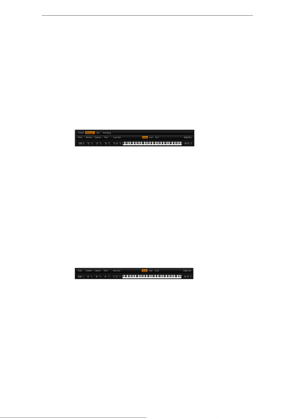
The Ranges Subpage
The layer Ranges subpage contains the following parameters:
Editing Programs
Poly
This setting is used to specify how many notes can be played at the same time.
Ö Unlike all the rest of the parameters of the Program page, the Polyphony setting is part
of the layer settings and therefore restored when you load a layer.
When a layer is defined as monophonic sound, the setting has no effect.
Octave
You can shift the octave of a layer by ±4 octaves.
Coarse (Tune)
You can shift a layer by ±12 semitones.
Fine (Tune)
You can detune a layer by ±100 cents.
Key Range (Low Key, High Key)
Each layer can be limited to a certain key range. You can set the range with the Low
Key and High Key values or by dragging the keyboard range control at its ends. When
you click and drag towards the middle of the keyboard, both values are moved at the
same time. As an additional option, you can use the MIDI input to set the range.
Simply click in the value field and play the note.
To set the key range:
1. On the Ranges subpage, click the Key button.
The key range options are shown on the subpage.
2. On the layer that you want to use, set the key range with the keyboard range
controls and/or Low Key/High Key value fields.
27
Editing
Page 28
Editing Programs
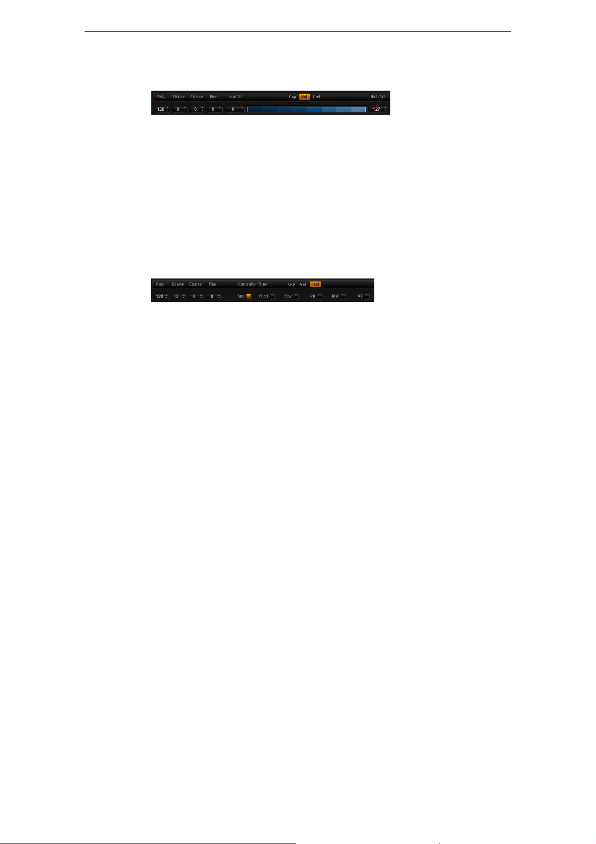
Velocity Range (Low Vel, High Vel)
Each layer can be limited to a certain velocity range. You can set the range with the
Low Vel and High Vel values or by dragging the graphical velocity range control at its
ends. When you click and drag towards the middle of the velocity range control, both
values are moved at the same time.
To adjust the velocity range, proceed as follows:
1. On the Ranges subpage, click the Vel button.
The velocity range options are shown on the subpage.
2. On the layer that you want to use, set the velocity range with the velocity range
control and/or Low Vel/High Vel value fields.
Controller Filter
You can separately filter out the most commonly used MIDI controllers for each layer.
For example, when you set up a program with a keyboard split, e.
both layers receive the same MIDI controllers. However, you usually do not want the
bass to receive the sustain pedal. To avoid that all layers in the program receive the
same MIDI controllers, use the controller filter.
To filter out the most commonly used MIDI controllers:
1. On the Ranges subpage, click the Ctrl button.
2. On the layer that you want to use, click the button for the MIDI controller that you
want to filter out.
The following MIDI controllers and messages can be filtered out: Sustain #64,
Foot Controller #4, Foot Switches #65–69, Pitchbend, Modulation Wheel #1 and
Aftertouch.
The Quick Controls Subpage
Here you can make settings for the quick controls in the performance section of the
HALion Sonic window. For more information, see
The NoteExp Subpage
Note Expression is Steinberg’s key technology for creating realistic instrument
performances. For more information, see
g., a bass and a pad,
“The Quick Controls” on page 167.
“Note Expression” on page 177.
28
Editing
Page 29
Editing Layers
A program contains up to four layers. Each layer can be edited separately. The
available parameters vary depending on the type of the selected layer (sample, synth,
drum, loop, or instrument layer).
To edit a layer, proceed as follows:
1. In the Multi Program Rack, select the program that contains the layer you want to
edit.
Editing Layers
2. Click Edit to open the Edit page.
3. Select the Layer Page button of the layer you want to edit, i. e., Layer 1, Layer 2,
Layer 3, or Layer 4.
Depending on the layer type, the corresponding editor (synth, sample, instrument,
drum or loop editor) opens.
Accessing the Parameters of Layers
The layer editor is divided into two sections, displaying the different parameters of the
layer.
To access the parameters of a layer, proceed as follows:
1. Select the layer you want to edit.
2. Click the page button for the parameter (such as Pitch, Filter, Amp, etc.) that you
want to access.
The corresponding subpage opens.
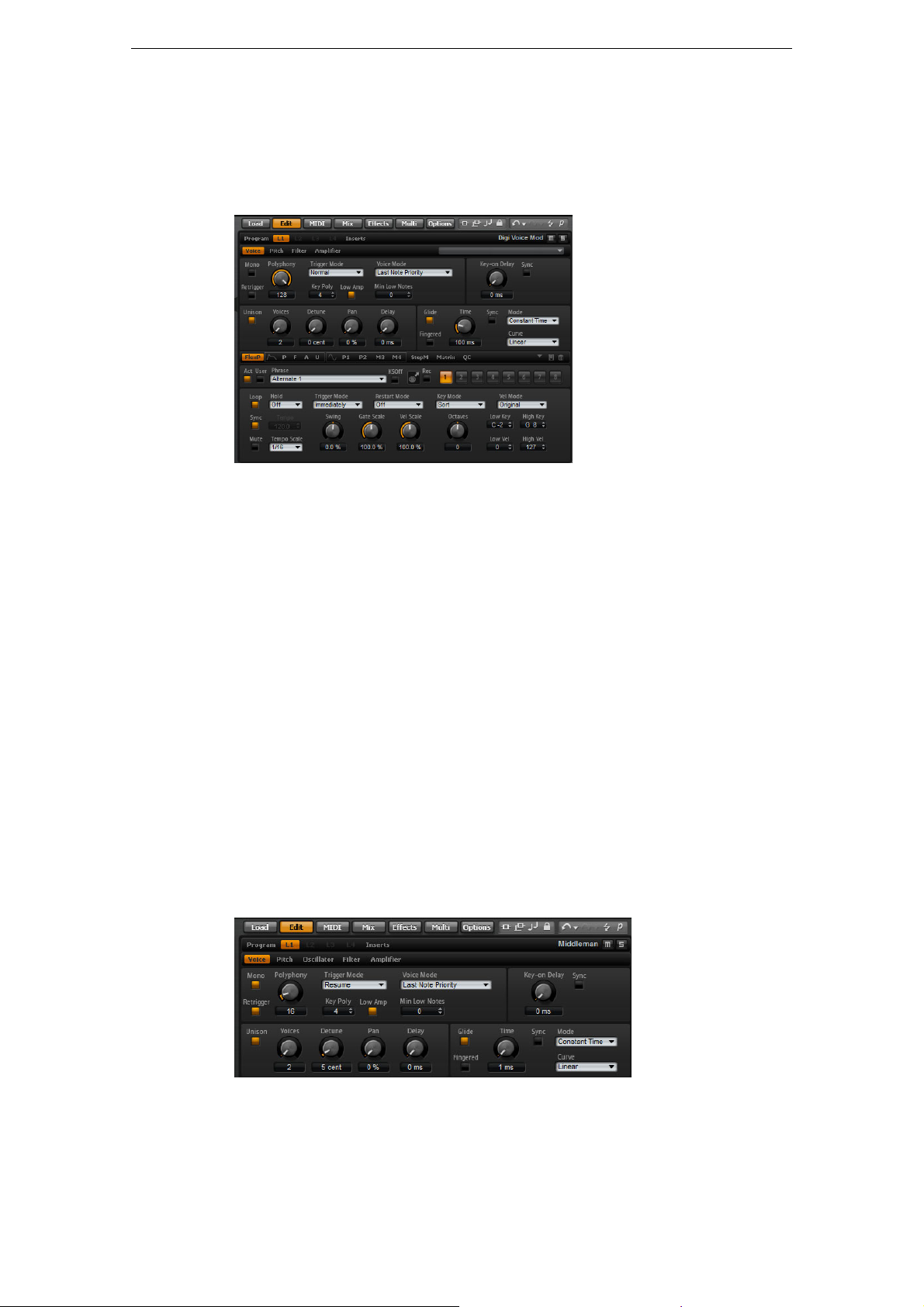
The Voice Subpage
The Voice subpage of the synth and sample layers gives you access to voice settings
of the layer which allows you to control the various Polyphony parameters, Trigger and
Voice modes. You can also configure the Unison feature and set the Glide parameter.
In addition, there is a Key On Delay control to delay the notes you play.
29
Editing
Page 30

Editing Layers
The Voice subpage contains the following parameters:
Mono
Here you can switch between monophonic and polyphonic playback:
• Activate Mono to switch to monophonic playback. Usually, this allows a more
natural sounding performance for solo instruments.
• Deactivate Mono to play polyphonically with the number of notes specified by the
Polyphony setting.
Retrigger
This option is only available if Mono is activated. It allows the retriggering of a stolen
note. When Mono and Retrigger are activated, a note that has been stolen by another
will be retriggered if you still hold the stolen note while you release the new one. For
example, with Mono and Retrigger activated, you can play trills by holding one note
and pressing/releasing another note repeatedly very fast.
Polyphony
Use this parameter to set an upper limit for the number of notes you can play in Poly
mode. You can set Polyphony between 2 and 128 notes.
Ö If the program has a smaller value for polyphony than the contained layers, the
maximum number of notes you can play will be limited by the setting of the program.
Key Poly
With this parameter you can set an upper limit for the number of notes you can play
per key. The last played notes have priority over the previously played notes of the
same key. Poly mode needs to be active to make this parameter effective.
Ö Key Polyphony works within the limits of the Polyphony setting. The lower of the two
settings is given priority.
Low Amp
When notes are stolen due to a Key Poly limitation, the oldest note is removed first by
default. By activating Low Amp the note with the lowest amplitude will be removed
instead.
Min Low Notes
Here you can specify a number of low notes that are prioritized. For example, set the
value to four if you want to preserve always the four lowest notes. The note stealing
will then affect notes from the fifth note on. Make sure that the polyphony of the
program is high enough for your specific Min Low Notes setting and allows to play
additional higher notes.
Trigger Mode
To avoid discontinuities during playback of envelopes and samples, you can select
one of three different characteristics for triggering notes:
Trigger Mode Description
Normal This mode triggers a new note when stealing the previous note,
which includes the envelopes being triggered from the start. A
sample of a sample zone will also be triggered from the start.
Resume This mode does not trigger a completely new note: If the new note
stays within the same sample zone, the envelopes retrigger but
resume at the level of the stolen note and the pitch of the zone will be
set to the new note. If the new note plays in a different zone, the new
note will play from the start including any envelopes and samples.
30
Editing
Page 31

Editing Layers
Trigger Mode Description
Legato This mode does not trigger a completely new note: If the new note
plays within the same sample zone, the envelopes keep running and
the pitch of the zone will be set to the new note. If the new note plays
in a different zone, the new note will play from the start including any
envelopes and samples.
Voice Mode
The Voice Mode specifies the conventions for stealing notes during playback and
whether new notes are being triggered when the Polyphony setting is exceeded. The
stealing and triggering of notes depends on the selected Voice Mode and your
keyboard playing. You can select one of the following Voice Modes:
Voice mode Description
Last Note Priority This mode guarantees the playback of the last played notes by
stealing the first played notes (First In, First Out). New notes have
priority over older notes.
If you exceed the maximum number of notes, the first played notes
will be stolen in their chronological order to make space for the last
played notes.
First Note Priority This mode guarantees the playback of the first played notes. Older
notes have priority over new notes.
If you exceed the maximum number of notes and still hold the first
played notes, no notes will be stolen. New notes will not be
triggered until a voice is free.
Low Note Priority This mode guarantees the playback of low notes. Low notes have
priority over high notes.
If you exceed the maximum number of notes playing a note higher
than those already playing, no note will be stolen and no new note
will be triggered.
If you exceed the maximum number of notes playing a note below
those already playing, the highest note will be stolen and the new
note will be triggered.
High Note Priority This mode guarantees the playback of high notes. High notes have
priority over low notes.
If you exceed the maximum number of notes playing a note below
those already playing, no note will be stolen and no new note will be
triggered.
If you exceed the maximum number of notes playing a note higher
than those already playing, the lowest note will be stolen and the
new note will be triggered.
Steal Lowest
Amplitude
Steal Released
Notes
This mode guarantees the playback of the last played notes by
stealing the notes with the lowest amplitudes. Notes with high
amplitude have priority over notes with low amplitude.
If you exceed the maximum number of notes, the note with the
lowest amplitude will be stolen to make space for the last played
note.
This mode steals notes that play in release first. Notes that are
being held have priority over notes that play in release. If no note
plays in release, the oldest note will be stolen instead.
If you exceed the maximum number of notes, the oldest note that
plays in release will be stolen to make space for the last played note.
If no note is playing in release and you exceed the maximum number
of notes, the first played notes will be stolen in their chronological
order to make space for the last played notes.
31
Editing
Page 32

Editing Layers
Key On Delay
With this feature you can delay the playback of the layer by an adjustable time or a
note value.
When you play a note, the playback of the layer will be delayed by the time or note
value that you have set with this parameter. With Sync deactivated, the delay is
specified in milliseconds. With Sync activated, the delay is specified in fractions of
beats.
• Set the Key On Delay time with the rotary encoder or by double-clicking in the
value field below the rotary encoder and entering a value.
• To synchronize the delay time to the host tempo, activate the Sync button and
select a note value from the pop-up menu.
To change the selected note value to a triplet, activate the “T” button.
Unison
Unison allows you to trigger multiple voices simultaneously with each note you play.
When you activate the Unison option, the following parameters become available:
Option Description
Voices By default, Voices has a value of 2. Setting higher values increases
the number of voices being triggered simultaneously. For a richer
sound, adjust the Detune, Pan and Delay parameters accordingly. Up
to 8 voices can be used.
Detune Use this to detune the pitch of each unison voice by the amount
specified in cents. Detuning the pitch of the voices results in a fatter
sound.
Pan Use this to spread the unison voices across the stereo panorama.
The higher the value, the broader the stereo image will be.
Delay With this parameter you can adjust a small random delay for each
unison voice. With a value of 0
the same time. Values from 1
each unison voice and the voices will not be triggered at the same
time anymore. The higher the value the more random the delay will be.
This is especially useful to avoid comb filter effects with two or more
slightly detuned samples, which would occur if you played them back
at exactly the same time.
% all unison voices will be triggered at
% to 100 % add a small random delay to
Glide
You can use Glide to bend the pitch between notes that follow each other. You
achieve the best results with Mono mode enabled. However, Glide also works
polyphonically.
When you activate the Glide option, the following parameters become available:
Option Description
Time This specifies the time needed to bend the pitch from one note to
the other. You can set a time between 1
Sync To synchronize the delay time to the host tempo, activate this option
and select a note value from the pop-up menu. To change the
selected note value to a triplet, activate the “T” button.
Mode Here you can specify whether the Glide Time is constant and
independent from the note interval (Constant Time) or if the time
changes with the note interval (Constant Speed). In the latter case
larger intervals result in longer glide times.
32
Editing
ms and 5000 ms.
Page 33

Option Description
Curve You can select one of three curves to define the glide behavior:
Fingered Activate Fingered to glide the pitch only between notes played
Ö If you use Cutoff, Amplitude and Pan Key Follow, the cutoff, amplitude and pan also
change with the Glide effect.
The Pitch Subpage
Editing Layers
With the Linear curve, the pitch glides at continuous speed from the
start to the end pitch. With the Exponential curve, the pitch starts
gliding at higher speed and decelerates towards the end pitch. For
example, this behavior is more similar to the natural pitch glide
produced by a singer. With the Quantized curve, the pitch glides in
semitones from the start to the end pitch.
legato.
The Pitch subpage of synth and sample layers gives you access to the tuning of the
layer. With the Octave, Coarse and Fine parameters, you can adjust the tuning in
steps of octaves, semitones and cents. In addition, you can adjust the amount of pitch
modulation from the Pitch Envelope, the keyboard or randomly with each keystroke.
Furthermore, you can set the pitchbend range for the up and down direction of the
pitchbend wheel separately.
The Pitch subpage contains the following parameters:
Pitchbend
Here you can set the range of the pitch modulation when moving the pitchbend wheel
up or down.
Octave
Here you can adjust the pitch in octave steps.
Coarse
Here you can adjust the pitch in semitone steps.
Fine
This parameter tunes the pitch in hundredths of a semitone (cents).
Env Amnt (Envelope Amount)
This parameter determines how much the pitch is affected by the Pitch Envelope.
Random
This parameter allows you to offset the pitch with each played note randomly. Higher
values cause stronger variations. At a setting of 100
from -6 to +6 semitones.
33
Editing
%, the random offsets can vary
Page 34

Key Follow
Here you can adjust the pitch modulation from MIDI note number. Set this parameter
to positive values in order to raise the pitch the higher you play. Use negative values to
lower the pitch the higher you play. At a setting of +100
played note exactly.
Center Key
This parameter determines the MIDI note that is used as the central position for the
Key Follow function.
The Oscillator Subpage
Editing Layers
%, the pitch follows the
The Oscillator subpage of the synth layer offers six sound sources: three main
oscillators, the sub oscillator, the ring modulation and the noise generator. To create
interesting electronic spectra, you can mix any of these sound sources. The resulting
signal is sent to the Filter and Amplifier sections for further sound shaping.
The three main oscillators (OSC 1, OSC 2 and OSC 3) offer different wave shapes and
algorithms. Select the wave shape and algorithm with the oscillator type (see below).
• Activate the oscillators by clicking their On/Off buttons.
Ö Make sure to switch off the oscillators when the function is not needed. When
activated, they use CPU cycles even if they are not heard, such as in a situation where
the level is set to 0
Multi-Oscillator Mode
For the three main synth oscillators, you can activate the Multi-Oscillator mode. This
mode allows you to create a richer sound by producing up to 8 oscillators
simultaneously. The effect is similar to the Unison mode for the zone, but it requires
less performance.
• To activate Multi-Oscillator mode, activate the MOsc button.
When Multi-Oscillator mode is activated, you can click the edit button to show the
corresponding parameters.
%.
The following parameters are available:
Parameter Description
No. Determines the number of oscillators that play back simultaneously.
You can also set fractions of numbers. For example, with a setting of
2.5, you hear two oscillators at full level and a third one at half level.
34
Editing
Page 35

Editing Layers
Parameter Description
Det Detunes the oscillators.
Spr Narrows or widens the stereo panorama. With a setting of 0 %, you
create a mono signal, and with 100
Editing the Parameters in the Modulation Matrix
When Multi-Oscillator Mode is active for an oscillator, you can modulate the
corresponding parameters in the modulation matrix.
1. In the modulation matrix, open the Modulation Destinations pop-up menu.
2. On the Synth submenu, select the destination that you want to edit.
3. Set up the Modulation Source and Depth parameters.
OSC 1/2/3 Type
%, you create a stereo signal.
The Oscillator Type defines the basic sound character of the oscillator. The pop-up
menu first lists the wave shapes (Sine, Triangle, Saw or Square), followed by the type
of algorithm (PWM, Sync, CM or XOR). The combination of waveform and algorithm
controls how the oscillator sounds.
The following algorithms are available:
Algorithm Description
PWM PWM (pulse width modulation) is only supported by the square
wave shape. The waveform parameter sets the ratio between the
high and low of the square wave. A setting of 50
square wave. With settings below or above 50
produces rectangular waves.
Sync This algorithm provides different hard-sync oscillators where each is
a combination of a master and slave oscillator. The wave shape of
the slave oscillator (Sine, Triangle, Saw or Square) is reset with
each full wave cycle of the master oscillator. This means that a
single oscillator can already produce a rich sync-sound without
utilizing other oscillators as slave or master. The waveform
parameter adjusts the pitch of the slave oscillator producing the
typical sync-sound.
% produces a pure
% the oscillator
35
Editing
Page 36

Editing Layers
Algorithm Description
CM
(Cross Modulation)
XOR This algorithm compares two square waveforms with an XOR
Ö Except for PWM, all algorithms support the Sine, Triangle, Saw and Square wave
shapes. PWM supports Square wave only.
To select an oscillator type, proceed as follows:
1. In the OSC1, OSC2 or OSC3 section, click the icon that indicates the wave
shape.
A pop-up menu opens.
This algorithm provides a combination of two oscillators where a
master oscillator is modulating the pitch of a slave oscillator (Sine,
Triangle, Saw or Square) at audio rate. The waveform parameter
adjusts the pitch ratio between slave and master oscillator resulting
in a sound close to frequency modulation.
(exclusive or) operation. Depending on the outcome of the XOR
operation, the wave shape of a third oscillator (Sine, Triangle, Saw
or Square) is reset. The waveform parameter adjusts the pitch ratio
of the square oscillators resulting in a sound close to ring
modulation of the third oscillator.
2. From the menu, select the oscillator type to set the wave shape and algorithm you
want to use.
The waveform parameters for OSC1, OSC2 and OSC3 can be assigned as
modulation destinations in the modulation matrix.
OSC 1/2/3 Waveform
The waveform parameter allows you to modify the sound of the oscillator algorithm. Its
effect depends on the selected oscillator type (see above for details).
OSC 1/2/3 Octave (Oct)
Here you can adjust the pitch in octave steps.
OSC 1/2/3 Coarse (Crs)
Here you can adjust the pitch in semitone steps.
OSC 1/2/3 Fine
This parameter tunes the pitch in hundredths of a semitone (cents).
OSC 1/2/3 Level
This adjusts the output level of the oscillator.
Ö The waveform, pitch and level of oscillator 1, 2, and 3 can be modulated separately in
the modulation matrix.
Sub Oscillator (SUB)
The pitch of the sub oscillator is always one octave lower than the overall pitch of the
synth layer. If you modulate the pitch of the synth layer, the pitch of the sub oscillator
follows.
• To activate and deactivate the sub oscillator, click its On/Off button.
Ö Make sure that you switch off the sub oscillator when the function is not needed.
When kept on, it uses CPU cycles even if they are not heard, such as in a situation
where the level is set to 0
%.
36
Editing
Page 37

Editing Layers
The following parameters are available:
Parameter Description
Sub Oscillator Type Here you can select the wave shape of the sub oscillator. You can
choose between Sine, Triangle, Saw, Square, Pulse Wide and
Pulse Narrow.
Sub Oscillator Level This adjusts the output level of the sub oscillator.
Ring Modulation (RING)
Ring modulation produces the sums and the differences between the frequencies of
two signals.
• To activate the ring modulation, click the On/Off button.
Ö Make sure to switch off ring modulation when the function is not needed. When kept
on, it uses CPU cycles even if the Ring Modulation is not heard, such as in a situation
where the level is set to 0
The following parameters are available:
Parameter Description
Ring Modulation
Source 1/2
Ring Modulation
Level
%.
This allows you to select the sources that will be ring modulated. You
can select OSC1 or Sub as Source 1 and OSC2 or OSC3 as
Source 2. Make sure the corresponding oscillators are activated
when you select them. Otherwise, you will not hear any sound.
This adjusts the output level of the Ring Modulation.
Noise
Noise is used for non-pitched sounds. In addition to standard white and pink noise,
there are also band pass filtered (BPF) versions of white and pink noises.
• To activate the noise generator, click its On/Off button.
Ö Please make sure to switch off the noise generator when the function is not needed.
When kept on, it uses CPU cycles even if the noise is not heard, such as in a situation
where the level is set to 0
The following parameters are available:
Parameter Description
Noise Type Here you can select the sound color of the noise. You can either
Noise Level This adjusts the output level of the noise generator.
Ö The Sub Level, Ring Modulation Level and Noise Level can be modulated separately
in the modulation matrix (see
%.
select White, Pink, White BPF or Pink BPF.
“The Modulation Matrix Subpage” on page 57).
37
Editing
Page 38

The Filter Subpage
The Filter subpage of synth and sample layers offers settings to adjust the tone color
of the sound. Filters shape the harmonic content of a sound by removing or accenting
frequencies in the spectrum. HALion Sonic’s filter section is extremely versatile and
powerful. With the filter type you can select the basic sound character of the filter,
either with or without distortion. This feature is also useful to scale the CPU
consumption because filters without distortion use less CPU cycles. With the filter
mode buttons you can configure the filter section as a single filter, two filters in parallel
or serial connection, or as a morphing filter that allows you to blend between up to
four different filter shapes.
In general, filters are identified by their pass-band and amount of attenuation. The
cutoff frequency separates the pass-band from the stop-band. Frequencies in the
pass-band stay unprocessed, while frequencies in the stop-band will be attenuated or
removed. The amount of attenuation is specified in decibels per octave (dB/oct). For
example, a 12
octave above the cutoff frequency. Other typical filter types are high-pass, band-pass
and band-reject. Another type of filter is called all-pass. As its name suggests, it does
not attenuate frequencies. Instead, it shifts the phase of the signal. When mixed with
the original signal, certain frequencies will be attenuated again. For example, the
phase shifter would use this.
Editing Layers
dB/oct low-pass filter attenuates the high frequencies at 12 dB for each
Filter Type
By selecting the filter type you specify the basic sound character of the filter. HALion
Sonic offers up to 24 filter shapes (for details on filter shapes, see below).
Filter type Description
Off The filter section is switched off. Use this when no filter is needed
for your sound and/or when you want to save CPU cycles.
Classic This filter type offers 24 filter shapes with resonance.
Tube Drive This filter type offers a lot of character by adding warm, tube-like
distortion. You can set the amount of tube drive with the Distortion
parameter.
Hard Clip This filter type adds bright, transistor-like distortion. You can set the
amount of hard clipping with the Distortion parameter.
Bit Red This filter type adds digital distortion by means of quantization noise.
You can adjust the bit reduction with the Distortion parameter.
Rate Red This filter type adds digital distortion by means of aliasing. You can
adjust the rate reduction with the Distortion parameter.
Rate Red KF This filter type adds digital distortion by means of aliasing. You can
adjust the rate reduction with the Distortion parameter. In addition,
the rate reduction follows the keyboard, i.
higher the sample rate will be and vice versa.
e., the higher you play the
38
Editing
Page 39

Editing Layers
Filter Mode
With the buttons on the left of the Filter subpage you determine the overall filter
structure. The filter types Classic and Tube Drive provide the following options:
Filter mode Description
Single Filter This mode uses one filter with one selectable filter shape. You can
select any of the 24 filter shapes.
Dual Filter Se rial This mode uses two separate filters connected in series. You can
select any of the 24 filter shapes for each filter independently. The
parameters Cutoff and Resonance control both filters
simultaneously. However, you can offset the cutoff and resonance
of the second filter with the parameters CF Offset and Res Offset.
Dual Filter Parallel This mode uses two separate filters connected in parallel. You can
select any of the 24 filter shapes for each filter independently. The
parameters Cutoff and Resonance control both filters
simultaneously. However, you can offset the cutoff and resonance
of the second filter with the parameters CF Offset and Res Offset.
Morph 2 This mode morphs between filter shape A and B. You can select
any of the 24 filter shapes for filter shape A and B independently.
Adjust the morphing with the Morph Y parameter.
Morph 4 This mode morphs sequentially from filter shape A to D. You can
select any of the 24 filter shapes for filter shape A, B, C and D
independently. Adjust the morphing with the Morph Y parameter.
Morph XY This mode morphs freely between the filter shapes A, B, C and D. In
other words, the morphing can be any mix between the four filter
shapes. You can select any of the 24 filter shapes for filter shape A,
B, C and D independently. Adjust the morphing with the Morph X
and Morph Y parameters.
Filter Shape
Each filter type offers 24 different filter shapes. By selecting the filter shape you
determine which frequencies will be affected. The letters and numbers indicate the
filter shape: For example, LP12 is short for low-pass 12dB/oct. Depending on the
chosen filter mode, you can either select one, two or four shapes.
Filter shape Description
LP24 Low-pass filter with 24 dB/oct. Frequencies above the Cutoff will be
attenuated.
LP18 Low-pass filter with 18 dB/oct. Frequencies above the Cutoff will be
attenuated.
LP12 Low-pass filter with 12 dB/oct. Frequencies above the Cutoff will be
attenuated.
LP6 Low-pass filter with 6 dB/oct. Frequencies above the Cutoff will be
attenuated.
BP12 Band-pass filter with 12 dB/oct. Frequencies below and above the
Cutoff will be attenuated.
BP24 Band-pass filter with 24 dB/oct. Frequencies below and above the
Cutoff will be attenuated.
HP6+LP18 High-pass filter with 6 dB/oct. plus low-pass filter with 18 dB/oct.
(asymmetric band-pass filter). Frequencies below and above the
Cutoff will be attenuated. Attenuation is more pronounced for the
frequencies above the Cutoff.
39
Editing
Page 40

Editing Layers
Filter shape Description
HP6+LP12 High-pass filter with 6 dB/oct. plus low-pass filter with 12 dB/oct.
(asymmetric band-pass filter). Frequencies below and above the
Cutoff will be attenuated. Attenuation is more pronounced for the
frequencies above the Cutoff.
HP12+LP6 High-pass filter with 12 dB/oct. plus low-pass filter with 6 dB/oct.
(asymmetric band-pass filter). Frequencies below and above the
Cutoff will be attenuated. Attenuation is more pronounced for the
frequencies below the Cutoff.
HP18+LP6 High-pass filter with 18 dB/oct. plus low-pass filter with 6 dB/oct.
(asymmetric band-pass filter). Frequencies below and above the
Cutoff will be attenuated. Attenuation is more pronounced for the
frequencies below the Cutoff.
HP24 High-pass filter with 24 dB/oct. Frequencies below the Cutoff will
be attenuated.
HP18 High-pass filter with 18 dB/oct. Frequencies below the Cutoff will
be attenuated.
HP12 High-pass filter with 12 dB/oct. Frequencies below the Cutoff will
be attenuated.
HP6 High-pass filter with 6 dB/oct. Frequencies below the Cutoff will be
attenuated.
BR12 Band-reject filter with 12 dB/oct. Frequencies around the Cutoff will
be attenuated.
BR24 Band-reject filter with 24 dB/oct. Frequencies around the Cutoff will
be attenuated.
BR12+LP6 Band-reject filter with 12 dB/oct. plus low-pass filter with 6 dB/oct.
Frequencies around and above the Cutoff will be attenuated.
BR12+LP12 Band-reject filter with 12 dB/oct. plus low-pass filter with 12 dB/oct.
Frequencies around and above the Cutoff will be attenuated.
BP12+BR12 Band-pass filter with 12 dB/oct. plus band-reject filter with
12
dB/oct. Frequencies below, above and around the Cutoff will be
attenuated.
HP6+BR12 High-pass filter with 6 dB/oct. plus band-reject filter with 12 dB/oct.
Frequencies below and around the Cutoff will be attenuated.
HP12+BR12 High-pass filter with 12 dB/oct. plus band-reject filter with
12
dB/oct. Frequencies below and around the Cutoff will be
attenuated.
AP All-pass filter with 18 dB/oct. Frequencies around the Cutoff will be
attenuated.
AP+LP6 All-pass filter with 18 dB/oct. plus low-pass filter with 6 dB/oct.
Frequencies around and above the Cutoff will be attenuated.
HP6+AP High-pass filter with 6 dB/oct plus all-pass filter with 18 dB/oct.
Frequencies around the Cutoff will be attenuated.
Cutoff
Here you can adjust the Cutoff frequency of the filter. The effect depends on the filter
type you have selected.
40
Editing
Page 41

Editing Layers
X/Y Control
The X/Y control allows you to adjust two parameters simultaneously. This is especially
useful with the morphing filters where the X/Y control adjusts the blend between the
filter shapes. For the other filter modes, the X/Y control adjusts cutoff and resonance.
Depending on the selected filter type, the X/Y control adjusts different parameters:
Selected filter Description
Single, Dual Serial
& Dual Parallel
Morph 2 and 4 The X/Y control adjusts the morphing between the filter shapes on
Morph XY The X/Y control adjusts the morphing between the filter shapes AD
Resonance
This parameter emphasizes the frequencies around the cutoff. For an electronic
sound, increase the resonance. At higher resonance settings, the filter self-oscillates,
which results in a ringing tone.
The X/Y control adjusts the cutoff frequency on the horizontal and
resonance on the vertical axis.
the vertical (Morph Y) axis. The horizontal axis adjusts the cutoff
frequency.
and BC on the horizontal (Morph X) and AB and DC on the vertical
axis (Morph Y).
Distortion
This parameter adds distortion to the signal. The effect depends largely on the
selected Filter Type. At higher settings, it creates a very intense distortion effect.
Ö This parameter is only available for the Tube Drive, Hard Clip, Bit Red, Rate Red and
Rate Red KF filter types.
CF Offset
For the dual filters, this parameter allows you to offset the cutoff frequency of the
second filter (filter shape B).
Res Offset
For the dual filters, this parameter allows you to offset the resonance of the second
filter (filter shape B).
Velocity
This parameter adjusts the cutoff modulation from velocity. Set this parameter to
positive values to increase the cutoff with higher velocities. Use negative values to
decrease the cutoff with higher velocities.
Env Amnt (Envelope Amount)
Use this parameter to adjust the Cutoff modulation from the filter envelope. Setting
negative values inverts the direction of the modulation from the filter envelope.
Key Follow
Here you can adjust the cutoff modulation using the note number. The range is from
-200
% to +200 %. Set this parameter to positive values to raise the Cutoff with notes
above the Center Key. Use negative values to lower the Cutoff with notes below the
Center Key. At +100
% the Cutoff follows exactly the played pitch.
Center Key
This parameter determines the MIDI note that is used as the central position for the
Key Follow function.
41
Editing
Page 42

The Amplifier Subpage
The Amplifier subpage of synth and sample layers gives you access to the level and
pan settings of the layer. With level you adjust the loudness of the layer. With pan you
specify the position of the layer in the stereo panorama. Both level and pan can be
modulated by the MIDI note number. In addition, the pan position can be modulated
with each keystroke randomly or left-right/right-left in alternation.
Level
Here you can you can adjust the loudness of the layer.
Key Follow
Here you can scale the loudness across the MIDI keyboard. Set this parameter to
positive values to raise the loudness the higher you play. Use negative values to lower
the volume the higher notes you play.
Editing Layers
Center Key
This parameter determines the MIDI note that is used as the central position for the
Key Follow function.
Pan
Here you can set the position of a sound in the stereo panorama. A setting of -100 %
corresponds to hard left and a setting of +100
Mode
With this option you can specify how the loudness changes across the stereo
panorama. You can select between the four modes 0
• The 0dB option works like a balance control: Setting the pan control towards the
left fades out the right channel and vice versa. At the center position, the loudness
is not cut.
• The -3dB option uses the cosine/sine pan law: The loudness is cut by -3dB at the
center position, but the energy is preserved when moving the source signal across
the stereo panorama. The -3dB option sounds more natural. The transition from
hard left to hard right sounds much smoother than with the 0dB or the -6dB
setting.
• The -6dB option uses the linear pan law: The loudness is cut by -6dB at the center
position, and the energy is not preserved when moving the source signal across
the stereo panorama. The -6dB option sounds more synthetic. The transition from
hard left to hard right sounds more abrupt than with the -3dB setting.
% to hard right.
dB, -3 dB, -6 dB and Off:
• When set to “Off” no loudness correction is applied when a signal is panned
across the stereo panorama.
Random
This parameter allows you to offset the pan position with each played note randomly.
The strength of the randomization can be adjusted within a range from 0
Higher values cause stronger variations. At a setting of 100
vary from fully left to fully right.
42
Editing
%, the random offsets can
% to 100 %.
Page 43

Editing Layers
Alternate
This parameter allows you to alternate the pan position each time you play a note. For
example, a value of +100
hard left, and so on. You can specify the pan position for the first time when you hit a
note with the algebraic sign: For negative values the initial pan position will be left and
for positive values it will be right. With the value in percent you determine the deviation
across the stereo panorama.
Reset
The initial pan position is set once after HALion Sonic is loaded. Then, HALion Sonic
counts each note you played to determine the next pan position. To reset this counter,
click the Reset button next to the Alternate control.
Key Follow
Here you can adjust the pan modulation from MIDI note number. Set this parameter to
positive values to offset the pan position towards the right for notes above and
towards the left for notes below the Center Key. Use negative values to offset the pan
position towards the left for notes above and towards the right for notes below the
Center Key. At the maximum setting of +200
to hard right within two octaves: Fully left is reached one octave below and fully right
is reached one octave above the center key.
% means the first note plays hard right, the second note
% the pan position moves from hard left
Center Key
This parameter determines the MIDI note that is used as the central position for the
Key Follow function.
The Envelope Subpages
You can find the envelope subpages in the bottom section of the Edit page. The
envelope subpages of the synth and sample layers give you access to the four
envelopes of the layer, i.
these is a multisegment envelope with up to 128 nodes. The nodes specify the overall
shape of the envelope with their Time, Level and Curve parameters. The times and
levels of the envelope can be modulated by velocity. The Key Follow parameters
modulate times via MIDI note number. Curve allows you to adjust the curvature
between two nodes from linear to logarithmic or exponential behavior. The Sync
option allows you to synchronize the envelope times to the tempo of your host
application and you can set up a loop between two definable nodes. You can select a
second envelope that is displayed in the background of the edited envelope, serving
you as an optical or snap reference.
The Amp, Filter and Pitch envelopes are pre-assigned to the amplitude, the filter cutoff
frequency and the pitch of the layer. You can adjust the pre-assigned modulations in
the corresponding section of the layer. The purpose of the User envelope is freely
definable. You can select the User envelope as a source in the modulation matrix.
However, you can also use the Amp, Filter and Pitch envelopes as sources in the
modulation matrix.
To access the envelopes, proceed as follows:
e. Pitch (P), Filter (F), Amp (A) and User (U) envelope. Each of
1. Go to the Edit page and select the synth or sample layer you want to adjust.
2. In the lower section of the editor, click the button of the corresponding envelope
subpage.
43
Editing
Page 44

Editing Layers
• P: Click “P” to display the parameters of the pitch envelope. The pitch envelope
modulates the pitch over time. The pitch envelope is bipolar, which means it allows
for negative and positive values to bend the pitch up and down.
• A: Click “A” to display the parameters of the amplifier envelope. The amplifier
envelope shapes the volume over time.
• F: Click “F” to display the parameters of the filter envelope. The filter envelope
controls the cutoff frequency to shape the harmonic content over time.
• U: Click “U” to display the parameters of this free assignable user envelope. It is
bipolar, which means it allows for negative and positive values, for instance, to
modulate the pan from left to right.
Presets
Presets for different envelopes can be loaded and saved at the top right of the
corresponding subpage.
• To load a preset, click in the “Select Preset” field and select the preset from the
pop-up menu.
44
Editing
Page 45

• To delete the selected preset from your system, click the trash icon. Then, you will
be asked to confirm the deletion.
• To save a new preset, click the disk icon. A file dialog opens where you can name
and save your preset file.
Navigating in the Graphical Envelope Editor
The vertical axis of the graphical envelope editor displays the level. The horizontal axis
displays the time.
To zoom, use the following possibilities:
• To zoom in on the horizontal axis, use the “+” button to the right of the scroll bar
below the graphical editor.
• To zoom out, click the “-“button to the right of the scroll bar.
• In the timeline, click and drag up or down to zoom in or out at the current position.
• To zoom to a certain region, hold [Alt]/[Option] and drag the mouse over the
region.
To scroll, use the following possibilities:
• Drag the scroll bar to the left or right to scroll the envelope editor to a new position.
• Click in empty space next to the scroll bar to jump to the corresponding position in
the envelope editor.
Editing Layers
• Click the triangles to the left and right of the scroll bar to scroll through the
envelope step by step.
Envelope Zoom Snapshots
Envelope zoom snapshots save the current state of the graphical envelope editor. For
example, by saving two envelope zoom snapshots, one for the beginning and one for
the end of the envelope, you can conveniently switch between editing the attack and
release of the envelope.
Saving and Loading Envelope Zoom Snapshots
To the right of the scroll bar you find three numbered buttons which allow you to save
and load envelope zoom snapshots for the current envelope editor (Amp, Filter, Pitch,
or User). When saving an envelope zoom snapshot, it remembers the zoom factor and
scroll position of the graphical envelope editor. The zoom factor and scroll position will
be restored when loading the envelope zoom snapshot.
• To save the current state of the graphical envelope editor, [Shift]-click one of the
numbered buttons to the right of the scroll bar.
• To load a previously saved envelope zoom snapshot, click the corresponding
button. The button color changes to green indicating the snapshot is active.
Zooming or scrolling with the graphical envelope editor deactivates the Envelope
Zoom Snapshot. The button indicates this by turning gray.
Editing the Envelope
Each multisegment envelope has up to 128 nodes with the Time, Level and Curve
parameters. The nodes and their parameters specify the overall shape of the
envelope. You can edit one or multiple nodes using the graphical envelope editor or
by typing in values. Before you can edit nodes, you must select them.
45
Editing
Page 46

Editing Layers
Selecting Nodes
• Select a node by clicking the node in the graphical editor. Selected nodes turn
light blue in color. The focused node is indicated by an orange frame color. The
focused node displays its parameters in the text fields to the left of the graphical
envelope editor.
• With multiple nodes selected, use the Node pop-up menu above the text fields to
set the focus to a different node without losing the current selection.
• [Shift]-click on a node to add it to the selection. Selected nodes will be edited
together.
• In addition, you can select multiple nodes by drawing a rectangle with the mouse
around the nodes.
• With a single node selected, use the left or right arrow key to select the next or
previous node. In a multiselection, the focused node will change instead and the
previous or next node within the multiselection will be focused.
• Click in empty space in the background of the envelope to cancel the current
selection.
Adjusting the Time Parameter
The Time parameter specifies the duration between two nodes. The change in level
from the selected to the following node will be carried out in the duration set by the
Time parameter (0
is displayed in milliseconds and seconds, or fractions of beats (when Sync is
activated).
To adjust the Time parameter with the graphical envelope editor, proceed as follows:
• In the graphical envelope editor, select the nodes and drag them left or right to
decrease or to increase the times.
• For a higher resolution, hold [Shift] while moving the nodes.
• Hold [Ctrl]/[Command] while dragging to limit the movement to the time-axis
(horizontal positioning only).
To set the Time parameter by entering values with the keyboard, proceed as follows:
• In the graphical envelope editor, select the nodes you want to edit. Use the Env
Node pop-up menu to change the focus if necessary. Enter a value in the Time text
field to the left of the graphical envelope editor, and press [Enter].
Adjusting the Level Parameter
The Level parameter specifies the amplitude of the envelope at the position set by the
Time parameter. The Amp and Filter envelopes are unipolar. Therefore, the value
range for the level is 0
envelopes are bipolar, the value range for the level is from -100
(negative and positive values) for these envelopes.
ms – 30.000 s). Depending on the Sync mode, the Time parameter
% to +100 % (positive values only). The Pitch and User
% to +100 %
Ö You can change the polarity of the envelopes in the modulation matrix, for instance, to
map the range of the Amplifier Envelope (unipolar) to Pan (bipolar). However, the
envelopes always display their values with their default polarity.
To adjust the Level parameter with the graphical envelope editor, proceed as follows:
• In the graphical envelope editor, select the nodes and drag them up or down to
decrease or increase the levels.
• Hold [Alt]/[Option] while dragging to limit the movement to the level-axis (vertical
positioning only).
• For a higher resolution, hold [Shift] while moving the nodes.
46
Editing
Page 47

Editing Layers
To set the Level parameter by entering values with the keyboard, proceed as follows:
• In the graphical envelope editor, select the nodes you want to edit. Use the Env
Node pop-up menu to change the focus if necessary. Enter a value in the Level text
field to the left of the graphical envelope editor, and press [Enter].
Adjusting the Curve Parameter
The Curve option allows you to adjust the curvature between two nodes from linear to
logarithmic or exponential behavior. The range is from -10 to +10.
To adjust the Curve parameter with the graphical envelope editor, proceed as follows:
• In the graphical envelope editor, drag the curvature of the envelope segment up or
down to adjust the curvature towards logarithmic or down towards exponential
behavior.
• [Ctrl]/[Command]-click a curvature to reset it to linear behavior.
To set the Curve parameter by entering values with the keyboard, proceed as follows:
• In the graphical envelope editor, select the nodes you want to edit. Use the Env
Node pop-up menu to change the focus if necessary. Enter a value in the Curve
text field to the left of the graphical envelope editor, and press [Enter].
• Positive Curve values change the curvature towards logarithmic and negative
values towards exponential behavior.
Adding and Removing Nodes
The envelopes Amp, Filter, Pitch, and User can have up to 128 nodes. All nodes
added after the sustain node always affect the release stage of the envelope, i.
the key is released.
• To add a node, double-click at the position where you want to add the node.
• To remove a node, double-click the node you want to remove.
• [Delete] or [Backspace] removes multiple selected nodes.
Ö You cannot remove the first, the last or the sustain node.
Adding Nodes Using the Fill Function
The Fill function allows you to add multiple envelope nodes after the currently selected
nodes:
1. From the pop-up menu located to the right of the Fill button, select the number of
nodes you want to add.
2. In the graphical envelope editor, select the node after which you want to add
nodes. If several nodes are selected, the new nodes will be inserted after all
selected nodes.
3. If the Fixed function is deactivated, the added nodes are placed with the time
interval specified by the Time parameter of the currently selected node. If multiple
nodes are selected, the interval is specified by the focused node.
By activating Sync, you can specify the interval with the Sync note value. For
example, if 1/4 is selected, new nodes will be added at exact quarter note
intervals.
4. If the Fixed function is activated, the added nodes fill the space between the last
selected node and the following one.
e. after
5. Click the “Fill” button.
The nodes are added.
47
Editing
Page 48

Editing Layers
Positioning Nodes Using the Fixed Function
When Fixed is activated, only the selected nodes will be moved on the time-axis. With
Fixed deactivated, nodes that follow the currently edited nodes will also be moved on
the time-axis.
• Click “Fixed” to activate or deactivate the function.
Positioning Nodes Using the Snap Function
You can select a second envelope that is displayed in the background of the edited
envelope serving you as an optical or snap reference. Nodes you position with Snap
activated will snap to the nodes of the envelope that is shown in the background.
• From the pop-up menu located to the right of the Snap button, select the envelope
to be displayed in the background.
• Click “Snap” to activate or deactivate the function.
Using Sync
You can synchronize the envelopes to the tempo of your host application. This allows
you to set envelope times that relate to musical time intervals (for example 1 bar),
regardless of tempo changes made later on.
1. Click “Sync” to activate the envelope’s synchronization mode. Sync is active when
the button is highlighted. A grid spaced in fraction of beats appears in the
graphical envelope editor.
2. From the pop-up menu located to the right of the Sync button, select a note value.
This sets the resolution of the grid, i.
to when moved.
For example, if you specify a 1/4 note value, the nodes will snap to 1/4 note steps.
If the “T” button is activated, the note values correspond to triplet values.
• The Time text field of a node displays times in fractions of beats. The fraction will
always be reduced to the smallest possible value. For instance, “2/16” displays as
“1/8”.
• Envelope nodes that do not exactly match a note value display the note value
which they are closest to.
e. the minimum note value the nodes will snap
• Nodes that exactly match a note value are indicated by a red dot inside the handle
of the node. This can be useful, for example, when you switch the grid between
triplets and normal note values: The triplet nodes still indicate that they match a
note value, even if the grid shows normal note values.
You can also enter times by entering note values as fractions of beats. Proceed as
follows:
1. Select the nodes you want to edit.
2. Enter a note value as fractions of beats such as “1/4”. Type the letter “T” behind
the note value to enter triplet note values such as “1/8T”.
3. Hit [Enter].
The selected nodes will be set to the entered note value.
Selecting an Envelope Mode
You can select one of four envelope modes to specify how the envelope is played
back each time you hit a note. These modes can be selected from the Mode pop-up
menu. The following options are available:
• Sustain: The envelope plays from the first node to its Sustain. The Sustain level is
held as long as you play the note. When you release the note, the envelope
continues with the stages behind the Sustain. This mode is ideal for looped samples.
48
Editing
Page 49

Editing Layers
• Loop: The envelope starts playback from the first node to the loop nodes. The loop
will be repeated as long as the key is held. The envelope plays the stages behind
the Sustain when you release the note. This mode is ideal for adding motion to the
Sustain (which would be steady in Normal mode).
• One Shot: The envelope will be played from the first to the last node, even if you
release the note. The envelope has no Sustain stage. This mode is ideal for drum
samples.
• Sample Loop: This mode allows you to preserve the natural attack of the sample.
The decay of the envelope does not start until the sample has reached the sample
loop start. Set the second node to the maximum level. Then, use any of the
following nodes to shape the decay during the loop phase of the sample. This way,
the envelope only affects the level during the loop phase of the sample. The attack
of the envelope is still executed.
Ö The Sample Loop mode is only available for sample layers.
Setting up the Loop
You can set up the envelope to repeat its playback between the nodes you select.
Proceed as follows:
1. Set the envelope mode to “Loop”.
2. Adjust the loop with the graphical envelope editor:
• The loop is indicated by the green region in the graphical envelope editor. You can
specify the loop start and end by dragging the borders of the region.
• Drag the left border to the node where the loop should start.
• Drag the right border to the node where the loop should end.
Ö The loop region can only be set up in the Decay of the envelope, i. e. after the first and
before the sustain node.
Level Velocity Curve
You can select one of eight curves to specify how the incoming velocity translates to
the level of the envelope. The characteristic of each curve is displayed by a small icon.
The menu offers the following mathematical functions for velocity:
- 1 = Linear
-2 = Squared
- 3 = Squared Inverse
-4 = 2 Poles Squared
- 5 = 2 Poles Squared Inverse
-6 = Cubic
- 7 = Quadric
-8 = dB
-9 = Logarithmic
- 10 = Constant (127)
Level Velocity (Vel>Lev)
Use this parameter to adjust how the velocity affects the level of the envelope. The
level of the envelope depends on the setting of this parameter and how hard you hit a
note: Positive values increase and negative values decrease the level of the envelope
the harder you hit a note.
49
Editing
Page 50

Editing Layers
Velocity to Time (Vel>Time)
Use this parameter to adjust the influence of velocity on the times of the envelope.
Positive values decrease the times for higher velocity values. Negative values increase
the times for higher velocity values.
Segments
From the Segments pop-menu, you can select which stages of the envelope will be
affected by the Velocity to Time parameter.
Option Description
A The velocity affects the attack time only.
A+D The velocity affects all times until the sustain.
D The velocity affects all times until the sustain but without the attack.
A+R The velocity affects the attack and the release times.
All The velocity affects all times.
Key Follow and KeyF Rel
With Key Follow and KeyF Rel (Key Follow Release) you can scale the envelope times
across the keyboard. Key Follow scales all times before the Sustain node. KeyF Rel
scales all times after the Sustain node (which equals the Release of the envelope).
You can set a Center Key for the Key Follow and KeyF Rel functions. The envelope
times depend on the position where you play the keyboard and on the corresponding
Key Follow setting: Positive values decrease the times for notes above and increase
the times for notes below the Center Key; the envelope becomes faster the higher you
play. Negative values increase the times for notes above and decrease the times for
notes below the Center Key; the envelope becomes slower the higher you play.
Center Key
This parameter determines the MIDI note that is used as the central position for the
Key Follow and KeyF Rel functions.
The LFO Subpages
LFO is an abbreviation for low frequency oscillator. The synth and sample layers offer
four LFOs: LFO1 and LFO2 are polyphonic, LFO3 and LFO4 are monophonic.
Polyphonic means the LFOs are calculated per voice allowing for independent
modulations with each triggered note. You can use this to create a richer sound, for
example, with an independent pitch modulation per note. Monophonic means the
LFOs are calculated only once per layer. The same modulation will be sent to all
voices simultaneously. Monophonic LFOs are often used for modulations such as
tremolo and vibrato. LFO1 to LFO4 can be assigned freely in the modulation matrix.
For each LFO you can select from eight different waveforms with an additional shape
parameter. Frequency adjusts the speed of the modulation and Phase sets the initial
start of the waveform when the LFO is retriggered. In addition, you can synchronize
the LFO Frequency to the tempo of the host application. Furthermore, you can define
how the LFO is retriggered playing your keyboard. The polyphonic LFOs have an
additional envelope with Fade In, Hold and Fade Out that allows you to shape the
modulation intensity over time. Finally, the start of the modulation can be delayed.
To access the LFOs, proceed as follows:
1. Go to the Edit page and select the synth or sample layer you want to adjust.
2. In the bottom section of the editor, click the button of the corresponding page.
50
Editing
Page 51

Editing Layers
• To select one of the polyphonic LFOs, click P1 or P2. This refers to LFO1 and
LFO2 in the modulation matrix.
Polyphonic LFO page
• To select one of the monophonic LFOs, click M3 or M4. This refers to LFO3 and
LFO4 in the modulation matrix.
Monophonic LFO page
LFO Waveform and Shape
Waveform selects the basic type of waveform. Shape changes the characteristic of
the waveform.
Option Description
Sine This produces smooth modulation, suitable for vibrato or tremolo.
Shape adds additional harmonics to the waveform.
Triangle This is similar in character to Sine. The waveform periodically ramps up
and down. Shape continuously changes the triangle waveform to a
trapezoid.
Saw This produces a “ramp” cycle. Shape continuously changes the
waveform from ramp down to triangle to ramp up.
Pulse This produces stepped modulation, where the modulation switches
abruptly between two values. Shape continuously changes the ratio
between the high and low state of the waveform. Set shape to 50
% to
produce a square wave.
Ramp This is similar to the Saw waveform. Shape increasingly puts silence
before the sawtooth ramps up.
Log Shape continuously changes the logarithmic curvature from negative to
positive.
S & H 1 This produces random stepped modulation, where each step is
different. Shape puts ramps between the steps and changes the S & H
into a smooth random signal when fully turned right.
S & H 2 This is similar to S & H 1. The steps alternate between random high
and low values. Shape puts ramps between the steps and changes the
S & H into a smooth random signal when fully turned right.
51
Editing
Page 52

Editing Layers
Sync Mode
You can sync the LFO to the tempo of the host application. The behavior of the
Frequency parameter changes with the option you select:
Option Description
Off Select this to adjust the speed of the modulation in Hertz.
Tempo + Retrig Select this to adjust the speed of the modulation in fractions of
beats, for example, 1/4, 1/8, etc. You can also set dotted and triplet
note values. The restart behavior of the LFO depends on the
Retrigger setting.
Tempo + Beat Select this to adjust the speed of the modulation in fractions of
beats, for example, 1/4, 1/8, etc. You can also set dotted and triplet
note values. The LFO restarts with the transport of the host and
lines up to the beats of the song. The Retrigger setting does not
come into effect.
Retrigger Mode
This defines whether the LFO is restarted when a note is triggered. The waveform
restarts at the position you set with the Phase parameter. The polyphonic and
monophonic LFOs offer different Retrigger settings.
The polyphonic LFOs can only switch between Retrigger On and Off:
Option Description
Off The LFO runs freely.
On The LFO restarts with each note that is triggered.
The monophonic LFOs offer the following modes:
Option Description
Off The LFO runs freely.
First Note The LFO restarts when a note is triggered and no other notes are
held.
Each Note The LFO restarts each time a note is triggered.
Frequency
This controls the frequency of the modulation, i. e. the “speed” of the LFO. When Sync
is activated, the frequency is set in fractions of beats.
Phase
This sets the initial phase of the waveform when the LFO is retriggered.
Rnd (Random)
When this is activated, each note starts with a randomized start phase. The Phase
control is automatically disabled.
52
Editing
Page 53

Editing Layers
Additional Parameters for Polyphonic LFOs
The following parameters are only available for the polyphonic LFOs, i. e. LFO1 and
LFO2:
Parameter Description
Delay Delay determines the delay time between the moment you play a
note and the moment the LFO comes into effect.
Fade In Fade In determines the amount of time for the LFO to fade in after
the note has been triggered and the delay time has elapsed.
Hold Hold determines the amount of time the LFO is running before the
Fade Out is carried out.
Use the Envelope Mode “One Shot” or “Hold + Fade Out” to
activate the Hold time. With all other Envelope Modes, the Hold
time is omitted and acts as Sustain.
Fade Out Fade Out determines the amount of time for the LFO to fade out
after the hold time has elapsed or a note has been released.
Use the Envelope Modes “One Shot + Sustain” or “Sustain” to
deactivate the Fade Out. This avoids changes of the modulation
when the note has been released.
Inv (Invert Envelope)
When the Inv option is activated, the behavior of the LFO envelope is inverted: The
LFO modulation starts at its maximum level and decreases to zero in the time
specified by the Fade In. After the Hold time has elapsed, or when releasing a key, the
modulation increases to its maximum level in the time specified by the Fade Out.
Envelope Mode
Here you can select how the LFO envelope reacts to your playing on the keyboard:
The One Shot modes do not react to note-off events. In addition, you can select
whether the Hold and Fade Out segments act as sustain.
Option Description
One Shot Select this mode to play the envelope from start to end in the time
specified by Delay, Fade In, Hold, and Fade Out.
One Shot +
Sustain
Hold + Fade Out When you play a note, the Delay and Fade In are carried out. The
Sustain + Fade
Out
Sustain When you play a note, the Delay and Fade In are carried out. Both,
This mode is similar to One Shot: The Delay and Fade In are always
carried out when you play a note. The Hold and Fade Out are omitted.
Instead, they act as sustain.
envelope fades out after the time specified by Hold or when releasing
the note. Releasing the note during the Fade In starts the Fade Out
from the current level.
When you play a note, the Delay and Fade In are carried out. The
Hold acts as sustain. The Fade Out is carried out when releasing the
note. Releasing the note during the Fade In starts the Fade Out from
the current level.
the Hold and Fade Out act as sustain. Releasing a note during the
Fade In sustains the current level. This avoids a change in modulation
when the note has been released.
53
Editing
Page 54

Graphical Envelope Editing in the LFO View
You can adjust the times of the envelope with the graphical editor:
• The first node adjusts the delay time. Drag the node to the left to decrease and to
the right to increase the delay.
• The second node adjusts the Fade In time. Drag the node to the left to decrease
and to the right to increase the time.
• The third node adjusts the Hold time. Drag the node to the left to decrease and to
the right to increase the time.
• The fourth node adjusts the Fade Out time. Drag the node to the left to decrease
and to the right to increase the time.
The Step Modulator (StepM) Subpage
Editing Layers
Synth and sample layers feature a polyphonic step modulator for creating rhythmic
control sequences. The step modulator can be freely assigned in the modulation
matrix. The sequence can have up to 32 steps. By selecting a note value, the steps
can be synchronized to the tempo of the host application or you can specify a
frequency at which the sequence repeats. The Retrigger mode allows you to restart
the sequence either with the First Note or Each Note. The sequence continues when
this parameter is set to Off. You can define a slope for rising, falling or both edges of
the steps. This way, you can use the step modulator as an LFO with freely definable
shape.
To access the step modulator, proceed as follows:
1. Go to the Edit page and select the synth or sample layer you want to adjust.
2. Click the StepM page button.
The Step Modulator subpage opens.
Step Modulator Presets
At the top right of the StepM subpage, you can load and save presets for the step
modulator.
• To load a preset, click in the Select Preset field and select the preset from the
pop-up menu.
• To delete a preset from your system, click the trash bin button.
You will be asked to confirm the deletion.
• To save a new preset, click the floppy disk button.
A file dialog opens where you can name and save your preset file.
Editing Steps
To adjust the steps using the mouse, proceed as follows:
• To set the level of a step, click at the corresponding position in the graphical
editor.
• To set the exact value, drag the step up and down like a fader.
54
Editing
Page 55

Editing Layers
• To reset the level of a step to 0 %, [Ctrl]/[Command]-click the step.
• To reset all steps, [Shift]-[Ctrl]/[Command]-click in the graphical editor.
• To adjust all steps at once, [Shift]-click and drag a step.
• To draw a ramp with steps, hold down [Alt]/[Option] and draw a line.
• To draw symmetric ramps, hold down [Shift]-[Alt]/[Option] and draw a line.
You can adjust the steps by using the computer keyboard:
• Use the Step text field to select a certain step.
• To set the level of the selected step, enter the new value in the level text field.
• To increment or decrement the selected step, use the up and down arrow keys.
By default, the increment or decrement is in steps of 1 %. Hold [Shift] to increment
or decrement the selected step in steps of 0.1
While the graphical editor has the keyboard focus, you can use the left and right arrow
keys to select the previous or next step.
Steps
Here, you set the number of steps the sequence plays.
%.
Sync Mode
By setting a note value, you can synchronize the steps to the tempo of the host
application. Alternatively, you can specify a frequency at which the sequence repeats.
If you can set a note value or a frequency depends on the option you select here:
Option Description
Off Select this to adjust the speed at which the sequence repeats in
Hertz. Whether the sequence restarts when you play a note depends
on the selected Retrigger mode.
Tempo + Retrig Select this to adjust the length of the steps in fractions of beats, i. e.
1/4, 1/8, etc. The speed of the modulation depend on the number of
steps, the note value and the tempo you set in your host application.
By activating the T button, the note values become triplet note values.
Whether the sequence restarts when you play a note depends on the
selected Retrigger mode.
Tempo + Beat Select this to adjust the length of the steps in fractions of beats, i. e.
1/4, 1/8, etc. The speed of the modulation depend on the number of
steps, the note value and the tempo you set in your host application.
By activating the T button the note values become triplet note values.
The sequence restarts with the transport of the host and lines up to
the beats of the song. The Retrigger setting does not come into
effect.
Frequency
When Sync mode is set to “Off”, this controls the speed at which the sequence
repeats.
Note
When Sync mode is set to one of the tempo settings, this adjusts the length of the
steps in fractions of beats.
Triplets
By activating the T button, the note values you set with the Note parameter become
triplets.
55
Editing
Page 56

Editing Layers
Retrigger Mode
Here you can determine whether the sequence restarts when you play a note. The
Retrigger Mode parameter is only available when Sync mode is set to “Off” or “Tempo
+ Retrig”. The following parameters are available:
Option Description
Off The sequence is not restarted. Instead, it resumes playback at the
last position when you released the key.
First Note The sequence restarts when a note is triggered and no other notes
are already held.
Each Note The sequence restarts each time a note is triggered.
Slope
Depending on the setting you select here, the step modulator jumps from step to step
or ramps between the steps. You can define a slope for rising, falling or all edges of
the steps. The setting “None” produces hard steps. Use the Slope Amount parameter
to set the time it takes to ramp from one step to the other. The following settings are
available:
Option Description
None Hard Steps.
Rising Only rising edges are ramped.
Falling Only falling edges are ramped.
All All edges are ramped.
Amount
When Slope is set to “Rising”, “Falling” or “All”, the Amount parameter determines the
time it takes to ramp from one step to the other. The higher the setting, the smoother
the transitions between steps.
Step
Use this to select a step. The Level text field updates accordingly.
Level
This shows the level of the currently selected step.
Snap
When Snap is activated, the level of each step can only be adjusted in quantized
steps of 1/12th. This feature can be used to produce modulations in steps of
semitones, for example.
Producing Modulations in Steps of Semitones
To produce modulations in steps of semitones, proceed as follows:
1. On the StepM subpage, activate the Snap option.
2. In the Modulation Matrix, assign the Step Modulator to Pitch (see below).
3. Set the Modulation Depth to +12.
Now, the levels of the steps represent intervals in semitones.
4. Go back to the step modulator and adjust each step to the new interval.
56
Editing
Page 57

The Modulation Matrix Subpage
The Matrix page of synth and sample layers gives you access to additional
modulations of the layer. The concept of controlling one parameter by another is
called modulation. HALion Sonic offers many fixed assigned modulations such as the
amplitude and filter envelopes, or pitch key follow.
To assign additional modulations, use the modulation matrix. Assigning modulations
means to interconnect modulation sources such as LFOs and envelopes, with
modulation destinations like pitch, cutoff, amplitude, etc. The modulation matrix offers
you up to 32 freely assignable modulations, each with a source, a modifier and a
destination with adjustable depth. All modulation sources and destinations can be
assigned several times. The polarity of each source can be switched between unipolar
and bipolar behavior. A selectable modifier and user-definable curves and ranges give
you further control over the modulation.
To access the modulation matrix, proceed as follows:
Editing Layers
1. Go to the Edit page and select the synth or sample layer you want to adjust.
2. Click the Matrix subpage button.
The modulation matrix is divided into two sections separated by the vertical scroll bar.
The section to the left displays the modulation rows. Here, you can assign modulation
sources to destinations and adjust the modulation depth. In the section to the right,
you find settings for the curve and range editor to make further adjustments for the
currently selected modulation source.
Using the Modulation Rows
The modulation rows allow you to interconnect modulation sources with modulation
destinations and to adjust the modulation depth.
• The parameters for setting up a modulation can be accessed via 32 rows. Each
row is identified by a number which is displayed to the left of the row. Use the
scroll bar in the middle to access rows that are currently not visible.
• You can select modulation sources by using the Source pop-up menu at the top
left of each row (see
• The Modifier pop-up menu in the lower left of each row allows you to select a
second modulation source that controls the intensity of the first source or a
modifier that alters the modulation signal of the first source (see
Modifiers” on page 63).
• To switch the polarity of a source between unipolar and bipolar behavior, click the
button to the right of the corresponding source. Modifiers do not have a polarity.
Therefore, the polarity option is hidden when you select a modifier.
• To select the modulation destination, use the pop-up menu to the right of a row
(see
“Modulation Destinations” on page 60).
• Use the horizontal fader below the destination to adjust the modulation depth.
Usually, the modulation depth adjusts in percent (-100
pitch as modulation destination, the modulation depth adjusts in semitones (-60 to
+60 semitones).
“Modulation Sources” on page 59).
“Modulation
% to +100 %). If you select
57
Editing
Page 58

Editing Layers
• Click the Bypass button in front of the depth control to switch off the modulation
temporarily.
Managing Modulation Rows
To copy or move a modulation row, proceed as follows:
1. On the context menu for the source row, select “Copy Modulation Row” or “Cut
Modulation Row”.
2. On the context menu for the target row, select “Paste Modulation Row”.
• To insert an empty row, select “Insert Modulation Row” from the context menu.
• To remove a modulation row, select “Remove Modulation Row” from the context
menu.
Note that the list always contains 32 rows. If you remove a row, an empty row is
appended to the list.
Ö You can copy modulation rows across different programs and between different plug-
in instances.
MIDI Controller and Note Expression Smoothing
When a MIDI or a Note Expression controller is selected as modulation source, the
Smoothing parameter is available. This allows for parameter changes to occur more
gradually.
The following settings are available:
- Default: Uses the global Smoothing parameter set up on the Options page.
- 1 ms to 1000 ms: Determines the amount of smoothing.
- Off: Deactivates the Smoothing parameter.
Unipolar vs. Bipolar Sources
The polarity of a modulation source specifies the value range it produces.
• Unipolar sources produce positive values only. The sources modulate between 0
and +1.
• Bipolar sources produce negative and positive values. The sources modulate
between -1 and +1.
By default, some sources are unipolar and others are bipolar. However, you can
change the polarity of a modulation source any time you want.
• To change the polarity of a source, click the button to the right of the
corresponding source.
Using the Curve and Range Editor
You can set up a curve and range for each modulation source.
• The curve and range editor displays the settings of the currently selected source
marked by a frame in the corresponding modulation row. To adjust the settings of
a different source, click the button to the left of the source you want to edit.
• The curve editor allows you to change the characteristic of a modulation. The
displayed curve is superimposed on the modulation source.
This way, you can change the modulation, for example, from linear to exponential or
logarithmic behavior.
• By setting the minimum and maximum values, the modulation stays within the
specified range only. In addition, you can specify an offset and a range for the
modulation.
For example, with an offset and range of +50 % only the second half of the
displayed curve will be superimposed on the modulation.
58
Editing
Page 59

Editing Layers
• The curve editor offers different presets which you can select from the pop-up
menu above the curve. To set up your own curve, select the Custom preset from
the pop-up menu.
• You can edit the curve graphically with the mouse when the Custom preset is
selected. Double-click in the editor to insert a new node. Double-click on a node
to delete it. Drag the nodes to new positions to adjust the basic shape of the
curve. Drag the lines between the nodes up or down to change the curvature.
Setting up a Modulation
To set up a modulation, proceed as follows:
1. Select the synth or sample layer you want to adjust.
2. Click the Matrix subpage button.
3. In one of the modulation rows, select a modulation source and destination, such as
LFO1 as source and Pitch as destination.
4. Use the horizontal fader below the destination to adjust the modulation depth.
5. Play a few notes to hear the modulation.
6. You can select a modifier or change the polarity of the source.
For example, from the “Source 2” pop-up menu, select Pitch Bend as the modifier
and set its polarity to unipolar.
7. Play a few notes to hear the modulation and use the pitchbend wheel from the
example.
8. Finally, use the curve and range editor to limit the modulation range or to adjust the
characteristic of the modulation.
Modulation Sources
The modulation sources are available from the Source and Modifier pop-up menus.
HALion Sonic offers you the following modulation sources:
Option Description
LFO P1 The first LFO of the layer which produces cyclic modulation signals.
LFO P1 is polyphonic which means that each voice is modulated
independently.
LFO P2 The second LFO of the layer which produces cyclic modulation
signals. LFO P2 is polyphonic which means that each voice is
modulated independently.
LFO M3 The third LFO of the layer which produces cyclic modulation signals.
LFO M3 is monophonic and modulates all voices simultaneously.
LFO M4 The fourth LFO of the layer which produces cyclic modulation
signals. LFO M4 is monophonic and modulates all voices
simultaneously.
Amp Envelope The amplifier envelope of the layer. The shape of the envelope equals
the modulation signal. The amplifier envelope is unipolar.
Filter Envelope The filter envelope of the layer. The shape of the envelope equals the
modulation signal. The Filter envelope is unipolar.
Pitch Envelope The pitch envelope of the layer. The shape of the envelope equals the
modulation signal. The pitch envelope is bipolar.
User Envelope The user envelope of the layer. The shape of the envelope equals the
modulation signal. The user envelope is bipolar.
Step Modulator The step modulator of the layer. This produces cyclic, rhythmically
stepped modulation signals. The step modulator is bipolar.
59
Editing
Page 60

Editing Layers
Option Description
Glide The glide signal of the source. Glide is unipolar.
Key Follow This produces an exponential modulation signal derived from the
MIDI note number. Exponential means this source works with
destinations such as Pitch or Cutoff. Key follow is bipolar.
Note-on Vel Note-on velocity (how fast you hit a key) can be used as a modulation
signal. Note-on Vel is unipolar.
Note-on Vel
Squared
Note-on Vel
Normalized
Note-off Vel Note-off velocity (how fast you released a key) can be used as a
Pitch Bend The position of the pitchbend wheel can be used as a modulation
Modulation Wheel The position of the modulation wheel can be used as a modulation
Aftertouch Aftertouch (how hard you press a key down after you hit it) can be
MIDI Controller Any of the 127 available MIDI controllers can be used as a
Quick Control The quick controls of the layer can be used as a modulation signal.
Note Expression The eight note expression parameters of the program can be used as
Noise Produces a random modulation signal. Noise is bipolar.
Output The audio output of the layer can be used as a modulation signal.
Bus 1-16 Modulations that have been sent to one of the sixteen busses can be
The squared version of Note-on Vel. Squared means you need to
press the key harder to produce higher modulation values.
The note-on velocity is normalized via the velocity range of the
corresponding sample zone. At the lowest velocity of the sample
zone the modulation will be 0, at the highest velocity it will be 1.
modulation signal. Note-off Vel is unipolar. While most of the MIDI
keyboards cannot send note-off velocity messages, your sequencer
software will in most cases be able to produce such messages.
signal. Pitch Bend is bipolar.
signal. Modulation Wheel is unipolar.
used as a modulation signal. Aftertouch is unipolar. Some MIDI
keyboards cannot send aftertouch messages. However, your
sequencer software will in most cases be able to produce such
messages.
modulation signal. You can select the MIDI controller from the
corresponding submenu.
You can select the quick control from the corresponding submenu.
modulation signals for the layer. You can select the note expression
parameter from the corresponding submenu.
Output is bipolar.
used as sources again. This way, you can combine several
modulations to produce more complex signals. Select the
corresponding modulation bus to assign it as source.
Modulation Destinations
Depending on the selected type of layer, the available modulation destinations vary.
HALion Sonic offers you the following modulation destinations:
Option Description
Pitch Modulates the pitch of the layer. For example, assign one of the LFOs
to create a vibrato effect. When Pitch is selected, the modulation
depth adjusts in semitones (-60 to +60).
Cutoff Modulates the filter cutoff of the layer. For example, assign the step
modulator to create rhythmic patterns in the spectral timbre.
60
Editing
Page 61

Editing Layers
Option Description
Resonance Modulates the filter resonance of the layer. Resonance changes the
character of the filter. For example, assign velocity to resonance to
accent the filter the harder you hit a note.
Morph X Modulates the x-axis of the filter in Morph XY mode. Use this to
morph between the filter shapes AD and BC.
Morph Y Modulates the y-axis of the filter in Morph 2, Morph 4, or Morph XY
mode. For example, use this to morph between the filter shapes AB
and DC.
Cutoff Offset Modulates the cutoff offset of the second filter in serial or parallel
mode. For example, assign the modulation wheel to lower or raise the
cutoff of the second filter while you play.
Resonance Offset Modulates the resonance offset of the second filter in serial or parallel
mode. For example, assign the modulation wheel to lower or raise the
resonance of the second filter while you play.
Pan Modulates the position of the layer in the panorama. For example,
assign the User Envelope to move the layer around freely.
Level This modulation adds to the level setting of the layer. It is ideal for
effects such as tremolo.
Volume 1 This modulates the gain of the layer. The volume modulation
multiplies with the level of the layer. It is ideal for cross-fades between
layers.
Volume 2 Basically the same as Volume 1. Volume 1 and 2 are multiplied with
each other. This way, you can build more complex modulations. For
example, use Volume 1 for cross-fading between layers and Volume
2 for fading them in or out.
LFO1 Frequency Modulates the speed of LFO1. For example, assign Aftertouch to
control the speed of a vibrato effect while you play.
LFO1 Shape Modulates the waveform of LFO1. For example, assign Key Exp to
vary the waveform with the playing position on the keyboard.
LFO2 Frequency Same as LFO1 Freq, but for LFO2.
LFO2 Shape Same as LFO1 Shape, but for LFO2.
Step Mod
Frequency
Step Mod Slope Modulates the shape of the edges of the step modulator (the Slope
Amp Env Attack
Time
Amp Env Decay
Time
Amp Env Sustain
Level
Amp Env Release
Time
Modulates the speed of the step modulator. For example, assign an
LFO to increase or decrease the speed cyclically.
parameter has to be active). For example, assign the modulation
wheel to blend from hard to smooth edges.
Modulates the time of the amplifier envelope attack (the first segment
of the envelope). The attack time cannot be modulated continuously.
The time updates only when the segment starts.
Modulates the time of the amplifier envelope decay (all segments
after the attack and before the sustain). The decay time cannot be
modulated continuously. The time updates only when the segment
starts.
Modulates the level of the amplifier envelope sustain. The sustain
level cannot be modulated continuously. The level updates only when
the segment starts.
Modulates the time of the amplifier envelope release (all segments
after the sustain). The release time cannot be modulated
continuously. The time updates only when the segment starts.
61
Editing
Page 62

Editing Layers
Option Description
Filter Env Attack
Time
Filter Env Decay
Time
Filter Env Sustain
Level
Filter Env Release
Time
Pitch Env Attack
Time
Pitch Env Decay
Time
Pitch Env Sustain
Level
Pitch Env Release
Time
User Env Attack
Time
User Env Decay
Time
User Env Sustain
Level
User Env Release
Time
Bus 1-16 You can send any modulation to one of the sixteen busses, for
Modulates the time of the filter envelope attack (the first segment of
the envelope). The attack time cannot be modulated continuously.
The time updates only when the segment starts.
Modulates the time of the filter envelope decay (all segments after the
attack and before the sustain). The decay time cannot be modulated
continuously. The time updates only when the segment starts.
Modulates the level of the filter envelope sustain. The sustain level
cannot be modulated continuously. The level updates only when the
segment starts.
Modulates the time of the filter envelope release (all segments after
the sustain). The release time cannot be modulated continuously. The
time updates only when the segment starts.
Modulates the time of the pitch envelope attack (the first segment of
the envelope). The attack time cannot be modulated continuously.
The time updates only when the segment starts.
Modulates the time of the pitch envelope decay (all segments after
the attack and before the sustain). The decay time cannot be
modulated continuously. The time updates only when the segment
starts.
Modulates the level of the pitch envelope sustain. The sustain level
cannot be modulated continuously. The level updates only when the
segment starts.
Modulates the time of the pitch envelope release (all segments after
the sustain). The release time cannot be modulated continuously. The
time updates only when the segment starts.
Modulates the time of the user envelope attack (the first segment of
the envelope). The attack time cannot be modulated continuously.
The time updates only when the segment starts.
Modulates the time of the user envelope decay (all segments after the
attack and before the sustain). The decay time cannot be modulated
continuously. The time updates only when the segment starts.
Modulates the level of the user envelope sustain. The sustain level
cannot be modulated continuously. The level updates only when the
segment starts.
Modulates the time of the user envelope release (all segments after
the sustain). The release time cannot be modulated continuously. The
time updates only when the segment starts.
example, to produce more complex modulation signals. Select the
bus you want to send the signals to as a destination. To use the
modulation that was sent to a bus, assign the corresponding bus as a
modulation source.
The following destination is only available for sample layers:
Option Description
Sample Start Modulates the starting position of the sample playback. For example,
assign note-on velocity to play back more of the attack of a sample
the harder you hit a note. The sample start cannot be modulated
continuously. The parameter updates only when you hit a note.
62
Editing
Page 63

Editing Layers
Ö Support of modulation of the sample start depends on the content. The factory
content does not support this function.
The following destinations are only available for synth layers:
Option Description
Osc1/2/3 Pitch Modulates the pitch of the corresponding oscillator. For example,
assign one of the LFOs to detune the oscillator cyclically.
Osc1/2/3 Level Modulates the volume of the corresponding oscillator. For example,
assign the modulation wheel to fade the oscillator in and out while
you play.
Osc1/2/3 Multi
Detune
Osc1/2/3 Multi
Pan
Osc1/2/3 Multi
Voices
Osc1/2/3
Waveform
Sub Osc Level Modulates the volume of the sub oscillator. For example, assign the
Ring Mod Level Modulates the volume of the ring modulation effect. For example,
Noise Gen Level Modulates the volume of the noise generator. For example, assign
Modulates the detune of the individual oscillator voices produced by
multi-oscillator mode.
Modulates the pan position of the individual oscillator voices
produced by multi-oscillator mode.
Modulates the number of oscillator voices produced by multi-
oscillator mode.
Modulates the shape and character of the corresponding oscillator.
For example, assign one of the envelopes to change the character
of the oscillator over time.
modulation wheel to fade in the oscillator while you play.
assign the modulation wheel to fade in the ring modulation while
you play.
the modulation wheel to fade in the noise generator while you play.
Modulation Modifiers
The modulation modifiers are available from the Modifier pop-up menu.
Sample & Hold
The sample & hold modifier takes a sample of the modulation source whenever it
receives a trigger signal. It holds the sampled value until it gets a new trigger. This
way, you can quantize a continuous modulation signal. The sample & hold offers
different options you can select from the submenu:
Option Description
Trigger on Note On Select this to trigger the sample & hold manually: Each time you hit a
note, the sample & hold takes a sample.
Trigger on LFO1 Select this for periodic triggering of the sample & hold: The sample &
hold takes a sample each time the waveform of LFO1 crosses the
zero line upwards.
Trigger on LFO2 Select this for periodic triggering of the sample & hold: The sample &
hold takes a sample each time the waveform of LFO2 crosses the
zero line upwards.
Trigger on
Modulation Wheel
Select this to trigger the sample & hold manually: The sample & hold
takes a sample each time the modulation wheel passes the center
position.
63
Editing
Page 64

The FlexPhraser
Option Description
Trigger on Sustain Select this to trigger the sample & hold manually: Each time you
press the sustain pedal, the sample & hold takes a sample.
Sample until
Release
Mod Matrix Presets
At the top right of the Matrix subpage, you can load and save presets for the
modulation matrix.
• To load a preset, click in the Select Preset field and select the preset from the
pop-up menu.
• To delete a preset from your system, click the trash bin button.
You are asked to confirm the deletion.
• To save a new preset, click the floppy disk button.
A file dialog opens where you can name and save your preset file.
Select this to trigger the sample & hold through releasing a key: The
sample & hold takes constantly samples. It holds the last sample
when receiving a note-off.
The FlexPhraser
Each program features up to five arpeggio and phrase players: the so-called
FlexPhrasers. There is one FlexPhraser for each layer and one for the program. While
the program FlexPhrasers always work with phrases, the layer FlexPhrasers
functionality changes with the layer type.
For synth, sample, instrument or drum layers, a FlexPhraser can play back anything
from basic synth arpeggios over dynamic drum phrases to realistic accompaniment
phrases for guitar, bass, piano, etc. You can select from over 1400 phrases that suit a
wide range of musical instruments and styles. Depending on the selected phrase, the
FlexPhraser uses your live playing to modify the phrase in real-time. This allows you,
for instance, to re-harmonize phrases by playing different chords.
In the case of loop layers, the FlexPhraser triggers the slices of the loop with their
original timing and order. You can trigger a transposed version of the loop, playing
higher or lower in pitch. In addition, you can vary the order with a random function and
export the slice sequence to your host sequencer via drag and drop.
Ö When working with loops you can play the individual slices and the entire loop. For
this purpose the key range is divided into two halves. The lower half triggers the loop;
the top half can be used to play single slices. This different functionality is indicated by
keys shaded in green for the loop keys and normal black/white keys for the slices.
Keys that do not trigger anything appear in gray.
To edit the program FlexPhraser, proceed as follows:
1. Go to the Edit page.
2. At the top of the Edit page, click the Program button.
3. Go to the bottom section of the Edit page and click the FlexP button.
4. Click the Active button at the top left to activate the phrase.
64
Editing
Page 65

To edit a layer FlexPhraser, proceed as follows:
1. Go to the Edit page.
2. At the top of the Edit page, select a layer (L1, L2, L3, or L4).
3. Go to the bottom section of the Edit page and click the FlexP button.
Depending on the type of layer (instrument or loop), the look and parameter set of
the FlexPhraser varies slightly.
4. Click the Active button at the top left to activate the phrase.
FlexPhraser Presets
At the top right of the FlexPhraser subpage, you can load and save presets for the
FlexPhraser. In addition to the selected phrase, these presets also contain the
performance settings of the FlexPhraser, such as Tempo, Tempo Scale, Loop, Swing,
etc.
• To load a preset, click in the Select Preset field and select the preset from the
pop-up menu.
• To delete a preset from your system, click the trash bin button.
You will be asked to confirm the deletion.
• To save a new preset, click the floppy disk button.
A file dialog opens where you can name and save your preset file.
Ö Presets can only be saved and loaded for phrases, not for sliced loops.
The FlexPhraser
Loading Phrases for the FlexPhraser
Programs as well as synth, sample, instrument, and drum layers provide a FlexPhraser
for which phrases are available. The phrases are sorted into folders in a tree structure,
according to category, style, etc.
To load a phrase, proceed as follows:
1. Go to the top of the FlexPhraser and click in the Phrase field.
The phrase browser opens.
2. Click on a phrase to select it. Step through the available phrases until you find the
phrase that you want to use.
You can also search for a phrase with a specific name using the text search field at
the top of the phrase browser.
3. Double-click the phrase to load it.
In general, you can apply any phrase to any type of instrument. However, a phrase for
guitar might not be suitable for use with a piano, for example.
Ö Some FlexPhrases make extensive use of key switches to switch between multiple
playing styles of an instrument while playing. These phrases can be found in the
Construction Sets folder. They work best with the corresponding instrument layers.
Phrase Playback Types
HALion Sonic features a huge amount of phrase types organized in categorized
submenus such as Classic Arp, Synth Seq, Chord Seq, Bass and so on. Each folder
can contain several category submenus representing functional descriptions or
musical styles.
The Construction Sets submenu contains phrases especially made for HALion
Sonic’s instrument layers. These phrases use key switches to switch between
different playing styles to increase the realism of your performance.
65
Editing
Page 66

The FlexPhraser
The phrases that can be found in the various other categories use a number of
different playback types to allow phrase specific user interaction while playing.
These phrases use one of the following playback types:
Option Description
Playback of a drum
pattern
Playback only of the
played notes
Playback of a
programmed
sequence according
to the played chord
Mute
Activate the Mute button to stop playback of the phrase temporarily. The phrase will
still play in the background. When you deactivate Mute, playback resumes
immediately.
Pressing any note triggers the same rhythm pattern.
The phrase is played back using only the played note and its
octave notes.
Pressing only one note, the phrase is played back using the
programmed sequence — which means that notes other than the
ones you play are triggered. Adding notes to those already held,
changes the sequence accordingly — for example, the phrase
plays back according to the chord you play.
KS Off (Key Switches off)
Construction Set phrases that make use of key switches and noises usually work only
with programs for the same type of instrument. Programs without key switches and
noises would play back such events as normal notes that do not fit to the rest of the
phrase. To avoid the playback of key switches and noises, activate the KS Off option.
Ö Since this option filters out any note events that do not transpose with your playing,
drum phrases do not work when this option is activated.
Loop
Defines whether the phrase is played once or continuously in a loop. When this is
activated, the phrase plays in a loop.
Hold
With the Hold parameter, you can prevent the phrase from stopping or changing
when the keys are released. In addition, the Gated mode plays silently in the
background when you release the keys, and resumes playback at the current position
when you press the keys again.
You can select one of the following options:
Option Description
Off The phrase changes immediately when releasing a key. The phrase
stops immediately when releasing all keys.
On The phrase plays to end even when the keys are released. When the
Loop option is activated, the phrase plays continuously in a cycle.
Gated The phrase starts playback with the first key being played. It plays
silently in the background even when the keys are released, and
resumes playback at the current position when you press any of the
keys again. This way, you can gate the playback of the phrase.
66
Editing
Page 67

The FlexPhraser
Trigger Mode
The Trigger Mode defines when the FlexPhraser scans for new keys you play on the
keyboard.
You can select one of the following options:
Option Description
Immediately The FlexPhraser scans for new keys all the time. The phrase changes
immediately in reaction to your playing.
Next Beat The FlexPhraser scans for new keys upon new beats. The phrase
changes in reaction to your playing on each new beat.
Next Measure The FlexPhraser scans for new keys upon new measures. The phrase
changes in reaction to your playing on each new measure.
Restart Mode
Depending on the selected Restart Mode and your playing, you can restart playback
from the beginning of the phrase.
You can select one of the following options:
Option Description
Off The phrase runs continuously and will not restart upon chord or note
changes.
New Chord Select this to restart the phrase on new chords. However, the phrase
will not restart upon legato played notes, for example, if you play
additional notes to a chord you are holding already.
New Note Select this to restart the phrase with each new note you play. Here,
the phrase will restart also upon legato played notes.
Sync to Host Select this to align the phrase with the beats and measures of your
host application. The phrase aligns to the beats and measures each
time you start the transport.
Key mode
This option defines if the order of the notes, as played chronically on the keyboard,
affects the playback of the phrase.
You can select one of the following options:
Option Description
Sort The notes play in the order of the selected pattern. The chronological
order does not have an influence.
As Played The notes play in the chronological order as you played them on the
keyboard.
Direct The phrase itself does not output any note events. Instead, it outputs
controller events only. You hear the notes you play plus any controller
events of the phrase, such as pitchbend, volume, pan, etc. Not all
phrases contain controller data. Please consult the documentation of
the phrase to see if it does.
67
Editing
Page 68

The FlexPhraser
Vel Mode
This option specifies if the velocity of the notes you play affects the notes of the
phrase.
You can select one of the following options:
Option Description
Original The notes of the phrase play with the velocity as specified by the
original sequence data of the phrase.
As Played The notes of the phrase play with the velocity you are playing on the
keyboard.
Original +
As Played
Sync
To synchronize the phrase to the tempo of your host application, activate Sync. The
Tempo control is disabled when Sync is activated.
Ö In addition, you can set the Restart mode to “Sync to Host” (see below for details).
This aligns the phrase with the beats and measures of your host application.
The velocity of the sequence data of the phrase is scaled by the
velocity you are playing on the keyboard.
Tempo
When Sync is deactivated, use the Tempo control to set the internal playback speed
of the FlexPhraser. The playback speed of the phrase is specified in Beats per Minute
(BPM). In addition, Tempo Scale gives you further control over the playback speed.
The Tempo control is inactive when Sync is activated.
Tempo Scale
This parameter defines the rate at which notes are triggered, in other words, the
speed at which the phrase is running. You can specify a value in fractions of beats.
You can also set dotted and triplet note values.
When the Tempo parameter is 1/16 and you set this value to 1/8, for example, the
speed is cut to half. When you set it to 1/32, the speed is doubled. Other values
increase or decrease the speed accordingly.
Swing
Use this parameter to shift the timing of notes on even numbered beats. This way, the
phrase gets a swing feeling. Negative values shift the timing backward, and the notes
are played earlier. Positive values shift the timing forward, and the notes are played
later.
Gate Scale
This parameter allows you to shorten or lengthen the notes of the phrase. At a value of
100
% the notes play with their original gate length.
Vel Scale
This parameter allows you to raise or lower the note-on velocities of the phrase. At a
value of 100
Octaves
This setting extends the phrase playback to higher or lower octaves. Positive settings
extend the playback to higher and negative settings to lower octaves. For example, a
value of +1 first plays the phrase in the octave range you originally played. Then, it
repeats the phrase one octave higher.
% the notes are played with their original velocity.
68
Editing
Page 69

Play Range
Click here to show or hide the editor.
You can use the Play Range parameters to determine which keys and velocities
trigger the phrase playback.
Low Key
This defines the lowest key on which the phrase is triggered.
High Key
This defines the highest key on which the phrase is triggered.
Low Vel
This defines the lowest velocity on which the phrase is triggered.
High Vel
This defines the highest velocity on which the phrase is triggered.
User Phrases
The user pattern of the FlexPhraser has up to 32 steps. Each step has an adjustable
velocity, gate length, and transpose value. By setting the steps, adjusting their length,
or leaving pauses, you define the rhythm of the user pattern. Consecutive steps can
be combined to create longer notes. By selecting the mode, you define how the notes
play back. In addition, there are two MIDI control sequences, that is, each step can
send two modulation signals.
User Phrases
• To create your own phrases, activate the User button.
For user phrases, the regular FlexPhraser parameters are available, except for the
KSOff button.
Editing User Phrases
In the editor for the user phrases, you can make detailed settings for the user phrase.
• To open the editor, click the “Show Editor Page” button.
About the Curves
In the editor, you can display the velocity curve or two MIDI controller sequences for
the phrase.
• To select a curve, click the corresponding button to the left of the display.
69
Editing
Page 70

User Phrases
Defining the Pattern Length
• To specify the number of steps for the pattern, drag the pattern length handle to
the right or left.
Adding and Adjusting Steps
The height of a step represents its value. You can edit the steps in the following way:
• To activate all steps, select “Enable All Steps” from the context menu.
• To adjust a value, click a step and drag up or down.
• To adjust multiple steps, click and draw a curve.
• To adjust the velocity of all steps relatively, [Shift]-click and drag.
• To draw a ramp with steps, hold down [Alt]/[Option] and draw a line.
• To draw symmetric ramps at the beginning and the end of the sequence, hold
down [Shift]-[Alt]/[Option] and draw a line.
• To reset the velocity of a step to 127, [Ctrl]/[Command]-click the step.
• To reset the velocity of all steps to 127, hold [Shift]-[Ctrl]/[Command] and click a
step.
• To introduce a legato between two steps, click the number below the first of these
two steps, so that a small arrow is shown.
When legato is activated, the gate scale parameter is not taken into account.
For velocity steps, the width of a step represents its gate length. You can edit the
length in the following way:
• To adjust the gate length of a step, drag the right border of a step.
• To adjust the gate length of all steps, hold down [Shift] and drag the right border.
You can only adjust the length this way until a step reaches the next step.
Ö If you increase the gate length of a step so that it overlaps the following steps, these
are deactivated.
• To reset the length of a step to 1, [Ctrl]/[Command]-click its highlighted right
border.
• To reset the length of all steps, hold down [Shift]-[Ctrl]/[Command] and click on a
highlighted right border.
• To fill the gaps between consecutive steps, select “Fill Gap” or “Fill All Gaps” from
the context menu.
Each MIDI controller lane can send a MIDI controller. By selecting the same MIDI
controller as source in the Modulation Matrix, you can modulate any of the
destinations with the MIDI controller sequence.
• To assign a controller, open the MIDI controller pop-up menu and select the
controller or use the corresponding control on your hardware.
70
Editing
Page 71

User Phrases
Adjusting the Pattern
• To reverse the pattern, click the Reverse button.
• To duplicate short phrases, click the Duplicate button. The maximum number of
steps is 32, therefore, if you copy a phrase that contains more than 16 steps, it
cannot be copied entirely.
• To shift the rhythm of the user pattern, use the arrow buttons in the lower left
corner of the edit section.
If you shift the rhythm of the user pattern to the left, the first step is moved to the
end. If you shift the pattern to the right, the last step is moved to the beginning.
Mode
With this parameter, you define how the notes are played back.
The following modes are available:
Option Description
Step The last note that is received triggers a monophonic sequence.
Chord Triggers the notes as chords.
Up Arpeggiates the notes in ascending order.
Down Arpeggiates the notes in descending order.
Up/Down 1 Arpeggiates the notes in ascending, then in descending order.
Up/Down 2 Arpeggiates the notes in ascending, then in descending order.
Depending on the Key Mode, the highest and lowest note (Key
Mode = Sort) or the first and last note (Key Mode = As Played) is
repeated.
Down/Up 1 Arpeggiates the notes in descending, then in ascending order.
Down/Up 2 Arpeggiates the notes in descending, then in ascending order.
Depending on the Key Mode, the highest and lowest note (Key
Mode = Sort) or the first and last note (Key Mode = As Played) is
repeated.
Random Arpeggiates the notes in random order.
Activating Steps
You can activate steps by clicking the corresponding On/Off buttons. This can be
necessary if you change the gate length of one step so that it overlaps the following
step, thereby deactivating it.
Ö When you activate a step that was inactive because of an overlapping previous step,
the previous step is shortened.
Step Length
Determines the gate length of a step.
Transpose
Transposes the note by the specified number of semitones.
Key Replace
With this parameter, you can switch the Key Select function off or specify how
missing keys are replaced.
For example, if Key Select is set to “1 - 2 - 3 - 4” and you play a chord with 3 notes,
key 4 is considered “missing”.
71
Editing
Page 72

Key Select
User Phrases
The following settings are available:
Option Description
Off Deactivates Key Replace and Key Select. The selected arpeggio
plays back normally.
Arp The missing keys are replaced with the note that the arpeggio
would normally play.
Rest The missing keys are not replaced. The arpeggio plays a rest
instead.
1st The missing keys are replaced by the first note in the note buffer.
Last The missing keys are replaced by the last note in the note buffer.
All The missing keys are replaced by all keys in the note buffer. The
notes are played as a chord.
Ö The Key Replace setting can be set differently for each variation.
When the FlexPhraser scans the keyboard, it writes the pressed keys into a note
buffer. Depending on the selected Key Mode, this note buffer is sorted by pitch or in
the order that you played the keys. The Key Select feature allows you to play back a
defined key from the note buffer. You can set up Key Select for each step separately,
which allows you to create very elaborate user phrases.
Ö Key Select cannot be used in Step or Chord mode.
• To access the Key Select values of the steps, click the “Show Key Values” button
to the left of the editor.
• To switch between the available Key Select values for a steps, click the value and
use the scroll wheel.
The following options are available:
Option Description
P (Phrase) Plays the note that the user phrase would play according to the
1 - 8 Plays the corresponding key from the note list. Which key is played
L (Last) Always plays the last key from the note buffer. Depending on the
A (All) Select this to play all keys from the note buffer as a chord.
Wrap Parameter
For all modes except Step and Chord, you can use this parameter to restart the
arpeggio after a specified number of steps.
If the Octaves parameter is active, the arpeggio traverses the octaves and restarts
from the original octave after the specified number of steps.
Ö Deactivated steps are taken into account.
selected mode, for example, Up, Down, Up/Down 1, etc.
depends on the Key Mode setting. For example, when Key Mode is
set to “Sort”, the setting 1 plays the lowest key.
Key Mode, this is the highest note or the last note in the note buffer.
Ö In Step and Chord mode, the Wrap parameter only affects the Octaves setting.
72
Editing
Page 73

Managing User Phrases
• To load a phrase, click the phrase selector and select a phrase from the pop-up
menu.
• To save a phrase, click the disk icon.
• To delete a phrase, select it and click the trashbin icon.
Ö Saved phrases include the Mode, Key Replace, and Wrap parameters, as well as the
steps with their Level, Length, and Legato settings. The selected MIDI controllers or
any settings on the main FlexPhraser page are not saved.
Groove Quantizing User Phrases
To adapt the timing of a phrase to an external MIDI file, you can drop this MIDI file on
the Groove Quantize drop field. You can quantize the playback of the user phrase to
the timing of a sliced loop by dragging its MIDI file from the MIDI export drag field to
the Groove Quantize drop field.
Working with FlexPhraser Variations
The “Groove Quantize Depth” parameter to the right of the drop field determines how
accurately the phrase follows the timing of the MIDI file.
Exporting MIDI Phrases
The phrases played by the FlexPhraser depend on the notes that are played and
therefore cannot be exported directly. However, it is possible to generate exportable
phrases by recording the MIDI output of the FlexPhraser.
Proceed as follows:
1. Click the Record button.
The small arrow in the MIDI export field starts blinking to indicate record mode.
2. Play some notes.
3. When you are done, click the Record button again.
Recording stops and in the MIDI export field, the arrow remains lit to indicate that
a MIDI phrase can be exported.
4. Click the MIDI export field and drag the phrase on a MIDI track in your host
sequencer application.
Working with FlexPhraser Variations
Each FlexPhraser features eight variations that allow you to set up different phrases or
variations of phrases or loops. You can switch between them with the variation
buttons at the top right of the FlexPhraser. You can also remote-control the Variation
buttons using HALion Sonic‘s trigger pads. This also gives you the possibility to
switch between variations by playing the trigger keys assigned to the trigger pads.
Ö To avoid that the variation switches in the middle of a beat or measure, use the trigger
modes “Next Beat” or “Next Measure”.
73
Editing
Page 74

Creating Variations
You can either create a variation starting from scratch or by copying an existing one.
To start from scratch, proceed as follows:
1. Click a Variation button at the top right of the FlexPhraser.
2. Assign a phrase and edit the FlexPhraser settings.
The variation is instantly modified and can be recalled by clicking the Variation
button.
To copy an existing variation, proceed as follows:
1. Right-click the Variation button you want to copy.
2. From the context menu, select “Copy FlexPhraser Variation”.
3. Right-click the Variation button to which you want to paste the variation.
4. From the context menu, select “Paste FlexPhraser Variation”.
Ö The parameters Loop, Sync, Hold, Trigger Mode, Restart Mode, Key Mode, Vel Mode,
Low/High Key and Low/High Vel are not part of the variations. You set them up only
once per FlexPhraser.
Editing Drum and Loop Layers
Switching Variations With the Trigger Pads
You can switch between variations with the trigger pads of the performance section
(see
“Switching Between Variations” on page 175).
Editing Drum and Loop Layers
Drum and loop layers have the same set of controls. In the key map at the bottom of
the editor, you see the drum instruments or loop slices the layer contains, and how
they map across the keyboard. In the top section, you find the Pitch, Filter, Amplifier
and Output settings of the currently selected drum instrument or loop slice. The
bottom section also gives you access to the FlexPhraser, the monophonic LFO and
the layer quick control editor.
Using the Key Map
The key map indicates how the drum instruments or loop slices are mapped across
the keyboard.
To access the key map, proceed as follows:
1. Go to the Edit page and select the drum or loop layer you want to adjust.
2. Go to the bottom section of the drum or loop editor and click the Key Map button.
When using the key map, the following applies:
• Keys with a drum instrument or loop slice assigned display in normal white and
black.
• The names of the drum instruments or loop slices display vertically above the keys.
74
Editing
Page 75

• Keys with nothing assigned are disabled and are displayed in gray.
• In case of a loop layer, the pitched part of the keyboard is displayed in orange.
• Hidden parts of the keyboard can be accessed with the scroll bar below the
keyboard.
• Clicking a key plays and selects the corresponding drum instrument or loop slice.
Ö The key map is used for indication and selection only. The mapping of the drum
instruments and loop slices cannot be changed.
Editing Drum Instruments or Loop Slices
To edit a drum instrument or loop slice, you must select it first. You can select drum
instruments or loop slices with the key map or your MIDI keyboard.
Selecting With the Key Map
To select a drum instrument or loop slice with the key map, proceed as follows:
1. Go to the Edit page and select the drum or loop layer you want to adjust.
2. Go to the bottom of the drum or loop editor and click the Key Map button.
3. On the key map keyboard, click the key of the drum instrument or loop slice you
want to adjust.
Editing Drum and Loop Layers
4. The drum instrument or loop slice is selected and the parameters at the top will be
updated accordingly.
Multi Selection Editing
To edit multiple drum instruments or slices at the same time, you can use the
multiselection functionality of the key map:
• Select one key, press [Shift] and then click a second key to select all keys in
between.
• Press [Ctrl]/[Command] and click keys to add or remove them from the current
selection.
• Press [Ctrl]/[Command] and drag the mouse over the keys that you want to use to
draw a selection rectangle.
• Press [Shift]-[Ctrl]/[Command] and drag the mouse over the keys to add additional
keys to the current selection.
As soon as you start selecting multiple slices or drum instruments, changes may occur
on certain settings. In such cases, the changes are indicated on the corresponding
controls. The backgrounds of combo boxes turn red, value fields display their values in
red, switches turn red (or dimmed red if the focused slice/instrument is set to off) and
knobs show a red corona indicating the value range. Changing a parameter sets all
selected loop slices or drum instruments to the same value and the red indication for
that control disappears.
Selecting With the MIDI Keyboard
To select a drum instrument or loop slice with your MIDI keyboard, proceed as
follows:
1. Go to the Edit page and select the drum or loop layer you want to adjust.
2. In the title bar of the top section, activate the “Select Zones via MIDI” button.
3. On your MIDI keyboard, press the key that plays the drum instrument or loop slice
you want to adjust.
4. The drum instrument or loop slice is selected and the parameters at the top are
updated accordingly.
75
Editing
Page 76

Ö By default all parameter changes are only applied to the currently selected drum
instrument or loop slice. Click the “Sel” button at the right of the title bar of the top
section to switch to the “All” mode if you want to apply changes to all drum
instruments or loop slices. You can also play multiple keys at a time to create a
multiselection.
Accessing the Pitch, Filter, and Amplifier Parameters
To access the Pitch, Filter, and Amplifier parameters of a drum instrument or loop
slice, proceed as follows:
1. Go to the Edit page and select the drum or loop layer you want to adjust.
2. Go to the bottom section, open the Key Map subpage and select the drum
instrument or loop slice you want to edit. Alternatively, use your MIDI keyboard to
select the drum instrument or loop slice.
3. Go to the top section, select Pitch, Filter, or Amplifier and adjust the parameters to
your liking.
Ö Only the currently selected drum instrument or loop slice will be edited.
The Pitch Subpage
Editing Drum and Loop Layers
This subpage gives you access to the tuning of the drum instrument or loop slice.
With the parameters Octave, Coarse and Fine, you can adjust the tuning in steps of
octaves, semitones and cents. In addition, you can adjust the amount of pitch
modulation from the Pitch envelope or randomly with each keystroke. Furthermore,
you can set the pitchbend range for the up and down direction of the pitchbend wheel
separately.
The parameters on the left of the Pitch subpage correspond to the Pitch subpage
parameters of synth and sample layers. For a description of these parameters see
“The Pitch Subpage” on page 33.
The pitch envelope parameters on the right of the Pitch subpage correspond to the
envelope parameters of synth and sample layers. For a description of these
parameters see
“The Envelope Subpages” on page 43.
76
Editing
Page 77

The Filter Subpage
The Filter subpage offers settings to adjust the tone color of the drum instrument or
loop slice.
The available parameters correspond to the parameters on the Filter subpage for
synth and sample layers. For a description of these parameters, see
Subpage” on page 38.
For a description of the filter envelope parameters, see “The Envelope Subpages” on
page 43.
Editing Drum and Loop Layers
“The Filter
The Amplifier Subpage
The Amplifier subpage gives you access to the level and pan settings of the drum
instrument or loop slice. In addition, you can activate One Shot and Reverse playback.
With Level you adjust the loudness of the sound. With Pan you specify the position of
the sound in the stereo panorama.
In addition, the pan position can be modulated with each keystroke randomly or leftright/right-left in alternation. Finally, you can select the output for each drum
instrument or loop slice separately.
Apart from the One Shot and Reverse parameters, all other parameters correspond to
the parameters on the Amplifier subpage for sample and synth layers. For a
description of these parameters, see
“The Amplifier Subpage” on page 42.
77
Editing
Page 78

For a description of the amplifier envelope parameters, see “The Envelope Subpages”
on page 43.
One Shot
Activate this to ignore any MIDI note-off messages. The release segments of the
envelopes will not be played while this is active. Instead, the envelopes play until the
Sustain is reached and remain on that level as long as the sample plays back. Any
loop settings of the sample will be ignored. For normal playback without ignoring MIDI
note-off messages, deactivate this. The release segments of the envelopes and any
loop settings the sample might contain will be played back again. One Shot is active
when the button is lit.
Reverse
Activate this to play the sample in reverse (from end to start). Any loop settings the
sample may contain will be ignored while this is activated. For normal playback (from
start to end), deactivate this. Reverse is active when the button is lit.
The AUX Subpage
Editing Drum and Loop Layers
Each drum instrument and loop slice has individual send levels that feed the four
global AUX FX busses. This allows you, for instance, to add more reverb to the snare
drum and less effect to the bass drum.
AUX FX1 – 4
This adjusts the send levels for the four global AUX FX busses for each drum
instrument or loop slice separately.
Using the LFO of Loop Layers
In addition to the parameters described above, loop layers offer a monophonic LFO
with adjustable Depth for Pitch, Cutoff and Pan.
To access the LFO of loop layers, proceed as follows:
1. Go to the Edit page and select the loop layer you want to adjust.
2. Go to the bottom of the loop editor and click the LFO button.
When using the LFO of loop layers, the following applies:
• The modulation of Pitch, Cutoff and Pan goes to all slices simultaneously. The
modulation depth cannot be set separately per slice.
• The filter must be activated to hear the modulation of the Cutoff.
78
Editing
Page 79

• With a Resonance of 100 % you might hear clicks because the slice ends abruptly,
but the filter still produces a sound from self-oscillation. In such a case, go to the
corresponding FlexPhraser and reduce the Gate Scale until the clicks are gone. In
addition, you can adjust the amplifier envelope of the slices, for example, to
increase the release of the envelopes.
Apart from the Pitch, Cutoff, and Pan parameters, all other parameters correspond to
the parameters on the LFO pages for sample and synth layers. For a description of
these parameters, see
Pitch
This adjusts how much the LFO affects the pitch of the slices.
Cutoff
This adjusts how much the LFO affects the cutoff of the slices.
Pan
This adjusts how much the LFO affects the pan of the slices.
FlexPhraser for Loop Layers
Editing Drum and Loop Layers
“The LFO Subpages” on page 50.
When using loop layers, the FlexPhraser offers the following features:
Loop
This option defines whether the loop sequence is played once or continuously in
cycles. When activated, the loop sequence plays in cycles.
Hold
With Hold you can prevent the loop to stop or change when the keys are released. In
addition, the Gated mode plays silently in the background when you release the keys,
and resumes playback at the current position when you press the keys again.
You can select one of the following options:
Option Description
Off The loop stops immediately when releasing a key.
On The loop plays to end even when the keys are released. When the
Loop option is activated, the loop plays continuously in cycles.
Gated The loop starts playback with the first key being played. It plays
silently in the background even when the keys are released, and
resumes playback at the current position when you press any of the
keys again. This way, you can gate the playback of the loop.
Trigger Mode
The Trigger mode defines when the FlexPhraser scans for new keys you play on the
keyboard.
You can select one of the following options:
Option Description
Immediately The FlexPhraser scans for new keys all the time. The loop changes
immediately in reaction to your playing.
Next Beat The FlexPhraser scans for new keys upon new beats. The loop
changes in reaction to your playing on each new beat.
Next Measure The FlexPhraser scans for new keys upon new measures. The loop
changes in reaction to your playing on each new measure.
79
Editing
Page 80

Editing Drum and Loop Layers
Restart Mode
Depending on the selected Restart mode and your playing, you can restart playback
from the beginning of the loop.
You can select one of the following options:
Option Description
Off The loop runs continuously and will not restart upon note changes.
First Note The loop restarts when a note is triggered and no other notes are
already held.
Each Note The loop restarts each time a note is triggered.
Sync to Host Select this to align the loop with the beats and measures of your host
application. The loop aligns to the beats and measures each time you
start the transport.
Sync
To synchronize the loop to the tempo of your host application, activate Sync. The
Tempo control is disabled when Sync is activated.
Ö In addition, you can set the Restart mode to “Sync to Host”. This aligns the loop with
the beats and measures of your host application.
Tempo
When Sync is deactivated, use the Tempo control to set the internal playback speed
of the loop. The playback speed of the loop is specified in Beats Per Minute (BPM). In
addition, Tempo Scale gives you further control over the playback speed. The Tempo
control is inactive when Sync is activated.
Tempo Scale
This parameter defines the rate at which notes will be triggered, in other words, the
speed at which the loop is running. A value of 1/16 corresponds to the original speed
as specified under Tempo. Setting the value, for example, to 1/8 cuts the speed to
half. Setting it to 1/32 doubles it. Other values increase or decrease the speed
accordingly.
Swing
Use this parameter to shift the timing of notes on even numbered beats. This way, the
loop gets a swing feeling. Negative values shift the timing backward and the notes will
be played earlier. Positive values shift the timing forward and the notes will be played
later.
Start
This allows you to shift the start of the loop in steps of 1/4 notes. The length of the
loop is shortened accordingly.
Length
This parameter allows you to shorten the length of the loop in steps of 1/4 notes.
Ö The control range of Start and Length varies with the original length of the loop.
Gate Scale
This parameter allows you to shorten the notes that play back the slices. At a value of
100
% the slices play with their original gate length.
Quantize
This allows you to set up a quantization grid. You can force the timing of the slices to
play back only at the note value you select here.
80
Editing
Page 81

Editing Drum and Loop Layers
Amount
This parameter defines how much of the quantization grid is applied. A value of 100 %
means the slices play back only at the Quantize Note Value you specified. Smaller
values move the notes only partially towards the next Quantize Note Value. With a
value of 0
Key Follow
Here you can adjust the pitch modulation from note number. Set this parameter to
positive values to raise the pitch with notes above the Center Key. Use negative
values to lower the pitch with notes above the center key. At +100
follows the played note.
Ö The Key Follow parameter is limited to the keys that trigger the entire loop. It does not
affect the keys that play the single slices.
Center Key
This parameter determines the MIDI note that is used as the central position for the
Key Follow function.
Random
% no quantization is applied at all.
% the pitch exactly
To shuffle the playing order of the slices randomly, activate the Random button. To
play the slices with their original order, deactivate the Random button.
Ö The overall timing does not vary through this. Only the playing order of the slices
varies through this, for example, slice 3 plays instead of slice 1, etc.
Depth
Here you adjust how much the playing order of the slices will be shuffled. Lower this
value to keep the playing order of slices on the main beats. Raise this value to vary the
playing order of slices on the main beats as well.
This parameter is only available when Random is activated.
Trigger
Click this to shuffle the playing order again. Please note that this function changes the
pattern’s number.
This parameter is only available when Random is activated.
Pattern
To predictably recall a certain random pattern, you can enter the pattern number. If
you recall a loop with a certain depth and pattern, it always sounds the same.
This parameter is only available when Random is activated.
Exporting the Loop Sequence
The FlexPhraser of loop layers allows you to export the loop sequence as a MIDI part
for your host sequencer.
To export the loop sequence, proceed as follows:
1. Drag the icon that looks like a MIDI socket to the project window of you host
sequencer.
2. Drop the MIDI part to an existing MIDI track or to empty space, which creates a
new MIDI track.
3. Assign the MIDI track to the corresponding slot in HALion Sonic.
81
Editing
Page 82

Loop FlexPhraser Variations
By activating Random and by adjusting the parameters Tempo, Tempo Scale, Swing,
Gate Scale, Quantize, Amount, Start and Length, you can create up to eight variations.
For further information, see
Ö The parameters Loop, Sync, Hold, Trigger Mode, Restart Mode, Key Follow and
Center Key are not part of the variations. You set them up only once per FlexPhraser.
Editing Instrument Layers
For easy editing, instrument layers have fewer controls. In the list at the top left, you
will see the expressions of the instrument layer. Typically, an expression is a certain
playing style of the instrument. In some cases, it can also be a part of the sound that
can be turned on or off, for instance, to add realism or to maximize the performance.
To the right and below, you will find the pitch, filter and amplifier settings of the
currently selected expression.
Editing Instrument Layers
“Working with FlexPhraser Variations” on page 73.
• Click the “On” button to load an expression. Note that you can use this option to
reduce the amount of used RAM by turning off individual expressions. You cannot
switch to an expression that has not been loaded before.
To edit an expression, proceed as follows:
1. Select the expression you want to edit in the list to the left.
2. On the right and below, adjust the parameters to your liking.
Only the selected expression will be modified.
To mute an expression, proceed as follows:
• Click the Mute button in the list on the left. The expression will not play back while
this is active.
• Click the button again to make the expression audible again.
Ö You can activate “Select Expression via MIDI” in the expression list if you want the
editor to follow incoming MIDI key switches or MIDI controller values.
82
Editing
Page 83

The Pitch Subpage
This subpage gives you access to the tuning of the expression. With the Octave,
Coarse and Fine parameters, you can adjust the tuning in steps of octaves, semitones
and cents. In addition, you can also set the amount of pitchbend.
The following parameters are available:
- Octave (see “Octave” on page 33).
- Coarse (see “Coarse” on page 33).
- Fine (see “Fine” on page 33).
- Pitch Bend Up and Down (see “Pitchbend” on page 33).
The Filter Subpage
The Filter subpage offers settings to adjust the tone color of the expression.
• To activate the filter, click the On button.
Expressions without filter use less CPU cycles. Therefore, you should only activate
this if your sound really needs a filter. The controls of the section turn dark when
deactivated.
The following parameters are available:
Editing Instrument Layers
- Filter shape (see “Filter Shape” on page 39)
- Cutoff (see “Cutoff” on page 40)
- Resonance (see “Resonance” on page 41)
The Amplifier Subpage
The Amplifier subpage gives you access to the level and pan settings of the
expression. With level you adjust the loudness of the expression. With pan you specify
the position of the expression in the stereo panorama.
The following parameters are available:
- Level (see “Level” on page 42)
- Pan (see “Pan” on page 42)
The Filter Env Modifiers Subpage
This subpage offers parameters to modify the filter envelope of the expression. You
can offset the Attack, Decay, Sustain and Release of the filter envelope. In addition,
you can also adjust the level velocity of the filter envelope.
Env Amnt (Envelope Amount)
Use this parameter to adjust the Cutoff modulation from the Filter Envelope. Setting
negative values inverts the direction of the modulation from the Filter Envelope.
Velocity
Use this parameter to adjust how velocity affects the level of the filter envelope. The
level of the envelope depends on the setting of this parameter and how hard you hit a
note: Positive values increase and negative values decrease the level of the envelope
the harder you hit a note.
Attack
Use this to offset the Attack time of the filter envelope. Positive values decrease and
negative values increase the Attack time.
Decay
Use this to offset the Decay time of the filter envelope. Positive values decrease and
negative values increase the Decay time.
83
Editing
Page 84

Sustain
Use this to offset the Sustain level of the filter envelope. Positive values increase and
negative values decrease the Sustain level.
Release
Use this to offset the Release time of the filter envelope. Positive values decrease and
negative values increase the Release time.
The Amplifier Env Modifiers Subpage
This section offers parameters to modify the amplifier envelope of the expression. You
can offset the Attack, Decay, Sustain and Release of the amplifier envelope. In
addition, you can also adjust the level velocity of the amplifier envelope.
Velocity
Use this parameter to adjust how velocity affects the level of the amplifier envelope.
The level of the envelope depends on the setting of this parameter and how hard you
hit a note: Positive values increase and negative values decrease the level of the
envelope the harder you hit a note.
Editing Instrument Layers
Attack
Use this to offset the Attack time of the amplifier envelope. Positive values decrease
and negative values increase the Attack time.
Decay
Use this to offset the Decay time of the amplifier envelope. Positive values decrease
and negative values increase the Decay time.
Sustain
Use this to offset the Sustain level of the amplifier envelope. Positive values increase
and negative values decrease the Sustain level.
Release
Use this to offset the Release time of the amplifier envelope. Positive values decrease
and negative values increase the Release time.
84
Editing
Page 85

Expression Maps
Using Expression Maps
For more realistic performances, many instrument layers use key switches to switch
between different expressions, i.
same instrument. These key switches are set to rather low keys to maximize the
playable range and they cannot be changed internally to ensure that performances
played by FlexPhrasers always sound the same – FlexPhrasers expect the key
switches of certain expressions on a specific MIDI note.
However, in some cases you need to shift the key switches into the playable keyboard
range to get access to them. You may also want to select the expression using a MIDI
controller. You can use so-called expression maps to customize the internal setting.
Selecting the Expressions
You can select which of the listed expressions you want to use in your expression
map. Expressions you do not activate will not be included in your expression map.
To activate or deactivate an expression, proceed as follows:
• Click the button to the left of the name of the expression.
Deactivated expressions turn dark.
Expression Maps
e. different articulations and playing styles of the
Ö Some instrument layers consist of multiple expressions that are not switchable via a
key switch. For example, instrument noises typically do not have a key switch
assigned. In this case, you can still select the individual expressions and edit them,
however, you cannot apply any key switch functionality. The key switch option menu is
therefore disabled.
Setting the Mode
To define whether you want to use only the internal key switches, to remap them to
other keys or to use a MIDI controller instead, open the options pop-up menu above
the expression list:
1. Go to the Edit page and select the layer you want to adjust.
2. Click the menu triangle on top of the expression list.
3. Select a mode. The following options are available:
Mode Description
Key Switch Only the internal key switches can be used to switch to an
Remapped The original key switches can be remapped to different keys.
MIDI Controller A MIDI controller can be used to remotely control the internal key
Ö No matter which condition you select, the internal key switch assignments still work in
parallel. This is mostly important for FlexPhrases that make use of the key switches.
The last key switch that is received always has priority.
expression.
switches.
Key Switch Mode
The Key Switch mode uses the internal key switch assignments. The key switches are
displayed in the list.
85
Editing
Page 86

Expression Maps
Remapped Mode
The Remapped mode allows you to transpose the fixed, internal key switch
assignments into the playable range of your MIDI keyboard. Each expression displays
the MIDI note of the internal key switch and a MIDI note for re-assigning the key
switch next to its name. The MIDI note of the internal key switch is for indication only
and cannot be edited.
To transpose the internal key switches, proceed as follows:
1. Set the mode to Key Switch.
2. Enter the MIDI note you want the expression to be reassigned to.
Ö The MIDI notes you use for key switches cannot be used to trigger samples anymore.
MIDI Controller Mode
The MIDI Controller mode allows you to define a MIDI controller that remotely controls
the internal key switches. The defined MIDI controller switches only between the
active expressions.
To assign a MIDI controller, proceed as follows:
1. Set the mode to MIDI Controller.
2. Open the menu again and select “Learn CC”.
3. Turn on the Hardware controller.
Temporary KS Mode
When you activate this option, expressions other than the default expression only
become active for as long as the corresponding key switch is held. This allows you to
“throw in” notes with other expressions by pressing a key switch temporarily. You
automatically return to the default expression when releasing this key switch.
Default Expression
This sets the default expression for Temporary KS Mode and the expression that will
be active after loading the program or layer.
To set the default expression:
1. Open the “Default Expression” submenu.
2. Select the expression you want to be the default.
86
Editing
Page 87

Editing Insert Effects
HALion Sonic offers you up to four insert effects for each of the four layers and for the
program itself. The insert effects you assign to a layer affect only that layer. The insert
effects you assign to the program affect all four layers together. Typically, you assign
effects like EQ or Distortion to the separate layers, but effects like Delay or Reverb to
the whole program.
Using the Insert Slots
Each layer and the program have four slots for assigning insert effects. The handling is
the same for all slots and corresponds to the global effects (see
Effect Slots” on page 131).
Editing Insert Effects
“Using the Insert
Adjusting the Levels
To the right of the insert slots you find faders for adjusting the output levels of the
program and layers.
To adjust the output level, proceed as follows:
• Drag the fader of the program or layer you want to adjust.
• Alternatively, enter a value in the text field below the fader.
Ö By changing the levels here, the corresponding parameters on the Program page will
change, too. Both parameters are the same.
87
Editing
Page 88

Introduction
The Auron synth uses granular synthesis with up to eight grain streams to produce
oscillator waveforms. With the integrated arpeggiator and step sequencer, you can
create anything from sequencer lines to stepped chords.
Auron
The granular oscillator is followed by a multi-mode filter that offers a large number of
different filter shapes. The filter can be modulated by modulation sources like the
keyboard, velocity, and LFO, but also by the controller lanes of the step sequencer, for
example.
Auron includes two LFOs for pitch, grain position, formant, and duration as well as
filter modulations. The first LFO can be synchronized to the tempo of the host
application and allows for modulations of grain position, formant and duration, as well
as filter cutoff. The second LFO is controlled by the modulation wheel and is used to
create a vibrato.
For the grain synthesizer, three pages are available: Osc, Mod, and Voice. To open a
page, click the corresponding button in the upper left of the Auron panel.
Selecting Samples
• To select a sample, click the selector in the upper left of the page and choose a
sample from the menu.
88
Page 89

The Osc Page
On this page, you can make settings for the grain oscillator.
Position
You can set the playback position of the grains manually. For example, at a setting of
50
%, the playback position is in the middle of the sample. The playback position is
updated with every new grain.
Position Random
Selects a random playback position within a certain range around the current position.
At a setting of 100
start and the end of the sample.
Duration
Increases the grain period by a factor ranging from 1 to 1000.
For very short grains, the sound gets the pitch of the frequency at which the grains
repeat. For grains longer than 30
Duration Random
The random grain duration is calculated at the start of a new grain.
The Osc Page
%, the playback position jumps to a random position between the
ms, the sound gets the pitch of the original sample.
KF (Key Follow)
Determines how the grain duration changes with the notes you play. It is mostly used
with short durations. Longer durations sound with the original pitch of the sample and
therefore do not need to follow the keyboard.
Pitch
Here, you can specify an interval between -12 and +12 semitones. The grains are
played randomly at their original pitch, or are transposed according to the pitch
interval. This parameter is suited for longer grain durations.
Pitch Random
Sets the random pitch range in semitones and cents. At a setting of +12, the random
pitch values lie between -12 and +12 semitones. This can be used to enrich the sound.
Level
Adjusts the overall level of the grain oscillator. When you increase the number of
grains, it might become necessary to lower the oscillator level. If you play back a very
quiet portion of a sample, you can use this control to raise the level.
Level Random
Sets a random level for each new grain. At a setting of 100 %, the level varies between
a factor of 0 and 2 of the original level.
Width
Narrows the stereo width of the grain oscillator. It is applied after the grain oscillator
and does not affect the stereo width of the actual sample. At a setting of 0
output of the grain oscillator is monophonic.
%, the
Gain
Allows you to automatically adjust the level of grains using quieter sample parts. This
way, you get a more homogenous signal and you can use a quiet part of a sample as
source.
89
Auron
Page 90

Grains
You can specify the number of grains, from 1 to 8. For example, with a setting of 4,
you get 4 grains per period of the grain duration.
To hear the effect of this setting, you have to play a new note.
The Mod Page
The Mod page contains the LFO settings in the upper section and the mod wheel, or
vibrato, settings in the lower section.
LFO Settings
LFO Waveform and Shape
Here, you can select the waveform for the LFO:
The Mod Page
Option Description
Sine This produces smooth modulation, suitable for vibrato or tremolo.
Shape adds additional harmonics to the waveform.
Triangle This is similar to Sine. Shape continuously changes the triangle
waveform to a trapezoid.
Saw This produces a ramp cycle. Shape continuously changes the
waveform from ramp down to triangle to ramp up.
Pulse This produces stepped modulation, where the modulation switches
abruptly between two values. Shape continuously changes the ratio
between the high and low state of the waveform. With Shape set to
50
%, a square wave is produced.
Ramp This is similar to the Saw waveform. Shape increasingly puts silence
before the sawtooth ramp up begins.
Log Shape continuously changes the logarithmic curvature from
negative to positive.
S & H 1 This produces randomly stepped modulation, where each step is
different. Shape puts ramps between the steps and changes the
S
& H into a smooth random signal when fully turned right.
S & H 2 This is similar to S & H 1. The steps alternate between random high
and low values. Shape puts ramps between the steps and changes
the S & H into a smooth random signal when fully turned right.
Freq
Controls the frequency of the modulation, that is, the speed of the LFO.
Sync
When Sync is activated, the frequency is set in fractions of beats.
Position
Controls the modulation depth of the grain position modulation.
Formant
Controls the modulation depth of the grain formant modulation.
90
Auron
Page 91

Duration
Controls the modulation depth of the grain duration modulation.
Cutoff
Controls the modulation depth of the filter cutoff modulation.
Mod Wheel Settings
Vib Freq
Controls the frequency of the second LFO that is used for pitch modulation (vibrato).
Vib Depth
Controls the depth of the vibrato modulation.
Position
Controls the influence of the mod wheel on the grain position.
The Voice Page
Formant
Controls the influence of the mod wheel on the grain formant.
Duration
Controls the influence of the mod wheel on the grain duration.
Cutoff
Controls the influence of the mod wheel on the filter cutoff.
The Voice Page
Polyphony
When Mono mode is not active, you can use this parameter to specify how many
notes can be played simultaneously.
Octave
Here, you can adjust the pitch in octave steps.
Coarse
Here, you can adjust the pitch in semitone steps.
Fine
Here, you can adjust the pitch in cent steps.
91
Auron
Page 92

The Voice Page
Fixed Pitch
Activate this option if you do not want the sample to be transposed over the keyboard.
When you work with short grain durations and “Duration Key Follow” is activated, the
pitch of the played key still follows the keyboard, and only the frequency response
changes.
Pitchbend Up/Down
Here, you can set the range for the modulation that is applied when you move the
pitchbend wheel.
Glide
You can use this parameter to bend the pitch between two notes that follow each
other. You achieve the best results in Mono mode.
Fingered
Activate this parameter to glide the pitch only between notes that are played legato.
Mono
Activates monophonic playback.
Retrigger
When this option is activated, a note that was stolen is retriggered if you still hold the
stolen note when releasing the new one. This lets you play trills by holding one note
while quickly and repeatedly pressing and releasing another note, for example.
Trigger Mode
Defines the trigger behavior for new notes. The following settings are available:
Option Description
Normal Triggers a new note when the previous note is stolen.
Resume The envelope is retriggered, but resumes at the level of the stolen
note. The pitch is set to the new note.
Legato The envelopes keep playing. The pitch is set to the new note.
92
Auron
Page 93

The Filter Section
Filter Parameters
Filter Shape
The filter shapes are the same as on the Filter subpage, see “Filter Shape” on page 39.
Cutoff
Controls the cutoff frequency of the filter.
Resonance
This parameter emphasizes the frequencies around the cutoff. At higher resonance
settings, the filter self-oscillates, which results in a ringing tone.
Distortion
This parameter adds distortion to the signal.
The following distortion types are available:
Option Description
Tube Adds warm, tube-like distortion.
Hard Clip Adds bright, transistor-like distortion.
Bit Reduction Adds digital distortion by means of quantization noise.
Rate Reduction Adds digital distortion by means of aliasing.
Rate Reduction Key
Follow
The Filter Section
As above, but with Key Follow: The rate reduction follows the
keyboard, so the higher you play, the higher the sample rate.
Env Amount
Controls the cutoff modulation from the filter envelope.
Velocity
Controls the cutoff modulation from velocity.
Key Follow
Here, you can adjust the cutoff modulation using the note number. Increase this
parameter to raise the cutoff with higher notes. At 100
pitch exactly.
Filter Envelope
Attack
Controls the attack time of the filter envelope.
Decay
Controls the decay time of the filter envelope.
Sustain
Controls the sustain level of the filter envelope.
Release
Controls the release time of the filter envelope.
%, the cutoff follows the played
93
Auron
Page 94

The Amp Section
Amp Parameters
Level
Controls the overall volume of the sound.
Velocity
Controls the level modulation from velocity. At 0, all notes are played with the same
level.
Amp Envelope
Attack
Controls the attack time of the amplifier envelope.
Decay
Controls the decay time of the amplifier envelope.
Sustain
The Amp Section
Sets the sustain level of the amplifier envelope.
Release
Sets the release time of the amplifier envelope.
The Arp Page
This page contains the same parameters as the FlexPhraser, see “The FlexPhraser” on
page 64.
94
Auron
Page 95

Introduction
Trium was designed to create modern and rich sounds. It comes with three oscillators,
a sub oscillator, a ring modulator, and a noise generator. With the integrated
arpeggiator and step sequencer, you can create anything from sequencer lines to
stepped chords.
Trium
The oscillators are followed by a multi-mode filter that offers a large number of
different filter shapes. The filter can be modulated using modulation sources like the
keyboard, velocity, and LFO, but also by the controller lanes of the step sequencer, for
example.
Trium includes two LFOs for pitch, PWM, and filter modulations. The first LFO can be
synchronized to the tempo of the host application and allows for filter cutoff, pitch, and
waveform modulation of the three main oscillators. The second LFO is controlled by
the modulation wheel and is used to create a vibrato.
95
Page 96

The Osc Page
The Oscillator page contains the same parameters as the Oscillator subpage, see
“The Oscillator Subpage” on page 34.
The following additional parameter is available:
Filter Envelope
Here, you can specify how much the modulation of the filter envelope influences the
oscillator waveform. This parameter is only available for oscillator types that allow
waveform modulation.
The Osc Page
The Sub Page
The parameters for the sub oscillator, the ring modulator, and the noise generator are
the same as those on the Oscillator subpage, see
34.
Voice Parameters
On the right, the Voice parameters are available.
Polyphony
When Mono mode is not active, you can use this parameter to specify how many
notes can be played simultaneously.
Octave
Here, you can adjust the pitch in octave steps.
“The Oscillator Subpage” on page
Pitchbend Up/Down
Here, you can set the range for the modulation that is applied when you move the
pitchbend wheel.
Glide
You can use this parameter to bend the pitch between two notes that follow each
other. You achieve the best results in Mono mode.
Fingered
Activate this parameter to glide the pitch only between notes that are played legato.
96
Trium
Page 97

Filter Section
The Sub Page
Mono
Activates monophonic playback.
Retrigger
When this option is activated, a note that was stolen is retriggered if you still hold the
stolen note when releasing the new one. This lets you play trills by holding one note
and quickly and repeatedly pressing and releasing another note, for example.
Trigger Mode
Defines the trigger behavior for new notes. The following settings are available:
Option Description
Normal Triggers a new note when the previous note is stolen.
Resume The envelope is retriggered, but resumes at the level of the stolen
note. The pitch is set to the new note.
Legato The envelopes keep playing. The pitch is set to the new note.
Filter Shape
The filter shapes are the same as on the Filter subpage, see “Filter Shape” on page 39.
Cutoff
Controls the cutoff frequency of the filter.
Resonance
This parameter emphasizes the frequencies around the cutoff. At higher resonance
settings, the filter self-oscillates, which results in a ringing tone.
Distortion
This parameter adds distortion to the signal.
The following distortion types are available:
Option Description
Tube Adds warm, tube-like distortion.
Hard Clip Adds bright, transistor-like distortion.
Bit Reduction Adds digital distortion by means of quantization noise.
Rate Reduction Adds digital distortion by means of aliasing.
Rate Reduction Key
Follow
As above, but with Key Follow: The rate reduction follows the
keyboard, so the higher you play, the higher the sample rate.
Env Amount
Controls the cutoff modulation from the filter envelope.
Velocity
Controls the cutoff modulation from velocity.
Key Follow
Here, you can adjust the cutoff modulation using the note number. Increase this
parameter to raise the cutoff with higher notes. At 100
pitch exactly.
97
Trium
%, the cutoff follows the played
Page 98

Filter Envelope
Attack
Controls the attack time of the filter envelope.
Decay
Controls the decay time of the filter envelope.
Sustain
Controls the sustain level of the filter envelope.
Release
Controls the release time of the filter envelope.
The Amp Section
Amp Parameters
Level
Controls the overall volume of the sound.
The Amp Section
Velocity
Controls the level modulation from velocity. At 0, all notes are played with the same
loudness.
Amp Envelope
Attack
Controls the attack time of the amplifier envelope.
Decay
Controls the decay time of the amplifier envelope.
Sustain
Sets the sustain level of the amplifier envelope.
Release
Sets the release time of the amplifier envelope.
The Mod Page
The Mod page contains the LFO settings in the upper section and vibrato settings in
the lower section.
LFO Settings
Freq
Controls the frequency of the modulation, that is, the speed of the LFO.
Sync
When Sync is activated, the frequency is set in fractions of beats.
98
Trium
Page 99

Pitch
Controls the modulation depth of the pitch modulation.
Cutoff
Controls the modulation depth of the filter cutoff modulation.
Osc1/2/3 Wave
These parameters control the modulation depth of the waveform modulation of the
three main oscillators. These controls are only available if the selected oscillator type
supports waveform modulation.
Mod Wheel Parameters
Vib Freq
Controls the frequency of the second LFO that is used for pitch modulation (vibrato).
The Arp Page
Vib Depth
Controls the depth of the vibrato modulation.
Cutoff
Controls the influence of the mod wheel on the filter cutoff.
Osc1/2/3 Wave
These parameters control the influence of the mod wheel on the waveform of the three
main oscillators. These controls are only available if the selected oscillator type
supports waveform modulation.
The Arp Page
This page contains the same parameters as the FlexPhraser, see “The FlexPhraser” on
page 64.
99
Trium
Page 100

Introduction
Voltage is a two-oscillator and noise synthesizer that can be used for synth basses,
but it also allows you to create any kind of classic monophonic and polyphonic synth
sound. With the integrated arpeggiator and step sequencer, you can create anything
from sequencer lines to stepped chords.
Voltage
The two oscillators and the noise generator are followed by a 24 dB low-pass filter.
The filter can be modulated using modulation sources like the keyboard, velocity, and
LFO, but also by the controller lanes of the step sequencer, for example.
Voltage includes two LFOs for pitch, PWM, and filter modulations. The first LFO can
be synchronized to the tempo of the host application and allows for filter and pitch
modulation. The second LFO is controlled by the modulation wheel and is used to
create a vibrato.
The Oscillator Section
Oscillator 1/2 Waveform
Here, you can choose a waveform for the oscillator: saw, triangle, or square.
Oscillator 1/2 Level
Controls the level of the oscillators.
100
 Loading...