


 Loading...
SURVEY PRO
for Recon & Nomad
User’s Manual
♥2008 Tripod Data Systems, Inc.
All Rights Reserved
TRIPOD DATA SYSTEMS SOFTWARE LICENSE AGREEMENT
IMPORTANT: BY OPENING THE SEALED MEDIA PACKAGE, YOU ARE AGREEING TO BE BOUND BY THE TERMS AND CONDITIONS OF THE LICENSE AGREEMENT AND LIMITATIONS OF LIABILITY ("Agreement"). THIS AGREEMENT CONSTITUTES THE COMPLETE AGREEMENT BETWEEN YOU AND TRIPOD DATA SYSTEMS, INC. ("Licensor"). CAREFULLY READ THE AGREEMENT AND IF YOU DO NOT AGREE WITH THE TERMS, RETURN THE UNOPENED MEDIA PACKAGE AND THE ACCOMPANYING ITEMS (including written materials and binders or other containers) TO THE PLACE WHERE YOU OBTAINED THEM FOR A FULL REFUND.
LICENSE. LICENSOR grants to you a limited, non-exclusive license to (i) install and operate the copy of the computer program contained in this package ("Program") on a single computer (one central processing unit and associated monitor and keyboard) and (ii) make one archival copy of the Program for use with the same computer. LICENSOR retains all rights to the Program not expressly granted in this Agreement.
OWNERSHIP OF PROGRAMS AND COPIES. This license is not a sale of the original Program or any copies. LICENSOR retains the ownership of the Program and all subsequent copies of the Program made by you, regardless of the form in which the copies may exist. The Program and accompanying manuals ("Documentation") are copyrighted works of authorship and contain valuable trade secrets and confidential information proprietary to LICENSOR. You agree to exercise reasonable efforts to protect LICENSOR'S proprietary interest in the Program and Documentation and maintain them in strict confidence.
USER RESTRICTIONS. You may physically transfer some Programs from one computer to another provided that the Program is operated only on one computer. Other Programs will operate only with the computer that has the same security code and cannot be physically transferred to another computer. You may not electronically transfer the Program or operate it in a time-sharing or service bureau operation. You agree not to translate, modify, adapt, disassemble, de-compile, or reverse engineer the Program, or create derivative works based on the Program or Documentation or any portions thereof.
TRANSFER. The Program is provided for use in your internal commercial business operations and must remain at all times upon a single computer owned or leased by you. You may not rent, lease, sublicense, sell, assign, pledge, transfer or otherwise dispose of the Program or Documentation, on a temporary or permanent basis, without the prior written consent of LICENSOR.
TERMINATION. This License is effective until terminated. This License will terminate automatically without notice from LICENSOR if you fail to comply with any provision of this License. Upon termination you must cease all use of the Program and Documentation and return them, and any copies thereof, to LICENSOR.
GENERAL. This License shall be governed by and construed in accordance with the laws of the State of Oregon, United States of America.
LIMITED WARRANTIES AND LIMITATION OF LIABILITY
LICENSOR grants solely to you a limited warranty that (i) the media on which the Program is distributed shall be substantially free from material defects for a period of NINETY (90) DAYS, and (ii) the Program will perform substantially in accordance with the material descriptions in the Documentation for a period of NINETY (90) DAYS. These warranties commence on the day you first obtain the Program and extend only to you, the original customer. These limited warranties give you specific legal rights, and you may have other rights, which vary from state to state.
Except as specified above, LICENSOR MAKES NO WARRANTIES OR REPRESENTATIONS, EXPRESS OR IMPLIED, REGARDING THE PROGRAM, MEDIA OR DOCUMENTATION AND HEREBY EXPRESSLY DISCLAIMS THE WARRANTIES OF MERCHANTABILITY AND FITNESS FOR A PARTICULAR PURPOSE. LICENSOR does not warrant the Program will meet your requirements or that its operations will be uninterrupted or error-free.
If the media, Program or Documentation are not as warranted above, LICENSOR will, at its option, repair or replace the nonconforming item at no cost to you, or refund your money, provided you return the item, with proof of the date you obtained it, to LICENSOR within TEN (10) DAYS after the expiration of the applicable warranty period. If LICENSOR determines that the particular item has been damaged by accident, abuse, misuse or misapplication, has been modified without the written permission of LICENSOR, or if any LICENSOR label or serial number has been removed or defaced, the limited warranties set forth above do not apply and you accept full responsibility for the product.
The warranties and remedies set forth above are exclusive and in lieu of all others, oral or written, express or implied. Statements or representations which add to, extend or modify these warranties are unauthorized by LICENSOR and should not be relied upon by you.
LICENSOR or anyone involved in the creation or delivery of the Program or Documentation to you shall have no liability to you or any third party for special, incidental, or consequential damages (including, but not limited to, loss of profits or savings, downtime, damage to or replacement of equipment and property, or recovery or replacement of programs or data) arising from claims based in warranty, contract, tort (including negligence), strict liability, or otherwise even if LICENSOR has been advised of the possibility of such claim or damage. LICENSOR'S liability for direct damages shall not exceed the actual amount paid for this copy of the Program.
Some states do not allow the exclusion or limitation of implied warranties or liability for incidental or consequential damages, so the above limitations or exclusions may not apply to you.
U.S. GOVERNMENT RESTRICTED RIGHTS
If the Program is acquired for use by or on behalf of a unit or agency of the United States Government, the Program and Documentation are provided with "Restricted Rights". Use, duplication, or disclosure by the Government is subject to restrictions as set forth in subparagraph (c)(1)(ii) of the Rights in Technical Data and Computer Software clause at DFARS 252.227-7013, and to all other regulations, restrictions and limitations applicable to Government use of Commercial Software. Contractor/manufacturer is Tripod Data Systems, Inc., PO Box 947, Corvallis, Oregon, 97339, United States of America.
Should you have questions concerning the License Agreement or the Limited Warranties and Limitation of Liability, please contact in writing: Tripod Data Systems, Inc., PO Box 947, Corvallis, Oregon, 97339, United States of America.
TRADEMARKS
Recon is a registered trademark and the TDS triangles logo, the TDS icons and Survey Pro are trademarks of Tripod Data Systems, Inc. Windows CE, ActiveSync, the Windows logo and Pocket PC are trademarks or registered trademarks of Microsoft Corporation in the United States and/or other countries. Bluetooth and the Bluetooth symbol are registered trademarks of Bluetooth SIG Inc. USA. CompactFlash is a registered trademark of SanDisk Corp. All other names mentioned are trademarks, registered trademarks or service marks of their respective companies. This software is based in part on the work of the Independent JPEG Group.
900-0031-XXQ |
052008 |
ii

Table of Contents
Welcome ________________________________________________ 1 Getting Started __________________________________________ 3
Manual Conventions _______________________________ 3 Survey Pro Installation______________________________ 4 Registering________________________________________ 4 Data Entry ________________________________________ 6
Smart SIP _________________________________________________ 6 Hardware Buttons__________________________________________ 8
Angle and Time Conventions ________________________ 9
Azimuths _________________________________________________ 9 Bearings __________________________________________________ 9 Time _____________________________________________________ 9
Using Survey Pro _________________________________ 11 Navigating Within the Program_____________________ 13
Command Bar ____________________________________________ 14
Parts of a Screen __________________________________ 17
Input Fields ______________________________________________ 17 Output Fields _____________________________________________ 17 Input Shortcuts ___________________________________________ 20 Quick Pick _______________________________________________ 24
Smart Targets ____________________________________ 25
Selecting Smart Targets ____________________________________ 25 Manage Smart Targets _____________________________________ 26
Map View________________________________________ 28 Basemaps ________________________________________ 30
Basemap Files ____________________________________________ 30 Manage Basemaps_________________________________________ 31
The Settings Screen________________________________ 33 File Management and ForeSight DXM _______________ 34 Job Files _________________________________________ 34 Raw Data Files____________________________________ 35 Control Files _____________________________________ 36
Import Control File ________________________________________ 36 External Control File_______________________________________ 36
Description Files __________________________________ 37
iii
Description Files without Codes _____________________________ 38 Description Files with Codes ________________________________ 39 Associating a Description File _______________________________ 40
Feature Codes ____________________________________ 41
Features __________________________________________________ 42 Attributes ________________________________________________ 42 Using Feature Codes in Survey Pro___________________________ 43
Layers ___________________________________________ 44
Layer 0 ___________________________________________________ 44 Other Special Layers _______________________________________ 44 Managing Layers __________________________________________ 45
Working with 2D Points ___________________________ 47 Polylines_________________________________________ 49 Alignments ______________________________________ 50
Creating an Alignment _____________________________________ 51
Conventional Fieldwork__________________________________57
Scenario One ______________________________________________ 58 Scenario Two _____________________________________________ 59 Scenario Three ____________________________________________ 60 Scenario Four _____________________________________________ 61 Summary _________________________________________________ 62
Data Collection Example ___________________________ 63
Setup ____________________________________________________ 63 Performing a Side Shot _____________________________________ 68 Performing a Traverse Shot _________________________________ 69 Data Collection Summary___________________________________ 71
Stakeout Example _________________________________ 72
Set Up____________________________________________________ 72 Staking Points _____________________________________________ 75 Point Staking Summary_____________________________________ 79
Surveying with True Azimuths _____________________ 80
Road Layout ____________________________________________83
Overview ________________________________________ 83
Horizontal Alignment (HAL)________________________________ 83 Vertical Alignment (VAL)___________________________________ 83 Templates ________________________________________________ 83 POB _____________________________________________________ 85
Road Component Rules____________________________ 85
Alignments _______________________________________________ 85 Templates ________________________________________________ 85
iv
Widenings and Super Elevations ____________________________ 86 Road Rules Examples ______________________________________ 88
Creating Templates _______________________________ 92 Building an Alignment ____________________________ 95 Putting the Road Together _________________________ 95 Staking the Road_________________________________ 102 Slope Staking the Road ___________________________ 104 Station Equation _________________________________ 106
DTM Stakeout _________________________________________ 109
Reference DTM Surface ___________________________ 109 Set Up the Job ___________________________________ 110
Select Your Layers________________________________________ 112 Select a Boundary (optional) _______________________________ 112 Select any Break Lines (optional) ___________________________ 114
Stake the DTM___________________________________ 115
View the DTM ___________________________________________ 116
Mapping Plane Scale Factor _____________________________ 119
Scale Factor Settings ______________________________________ 122 Accessing the Scale Factor Settings__________________________ 127 Working with a Scale Factor _______________________________ 128
Other Tutorials ________________________________________ 131
Import / Export _________________________________ 131
Importing *.JOB Coordinates_______________________________ 132 Importing *.CR5 Coordinates ______________________________ 132 Importing LandXML Files _________________________________ 134 Import Control___________________________________________ 137 Exporting Coordinates ____________________________________ 138
Repetition Shots _________________________________ 139
Repetition Settings Screen _________________________________ 139 Repetition Shots Screen ___________________________________ 141
Radial Sideshots _________________________________ 143 Shoot From Two Ends ____________________________ 147 Offset Shots _____________________________________ 148
Distance Offset Screen ____________________________________ 148 Horizontal Angle Offset Screen_____________________________ 149 Vertical Angle Offset Screen _______________________________ 150
Resection _______________________________________ 151
Performing a Resection____________________________________ 152
Solar Observations _______________________________ 154 v
Performing a Sun Shot_____________________________________ 155 What to Do Next__________________________________________ 158
Remote Control __________________________________ 159
The Remote Control Screen ________________________________ 159 Taking a Shot in Remote Mode _____________________________ 161 Stake Out in Remote Mode_________________________________ 162 Slope Staking in Remote Mode _____________________________ 164
GeoLock ________________________________________ 165
Configuring GeoLock _____________________________________ 166 Localizing _______________________________________________ 167 Using GeoLock ___________________________________________ 168
Slope Staking ____________________________________ 168
Defining the Road Cross-Section ____________________________ 169 Staking the Catch Point ____________________________________ 171
Intersection _____________________________________ 174 Map Check______________________________________ 175
Entering Boundary Data ___________________________________ 175 Editing Boundary Data ____________________________________ 176 Adding Boundary Data to the Current Project ________________ 176
Predetermined Area ______________________________ 177
Hinge Method____________________________________________ 177 Parallel Method __________________________________________ 178
Horizontal Curve Layout _________________________ 180
PC Deflection ____________________________________________ 180 PI Deflection _____________________________________________ 180 Tangent Offset ___________________________________________ 181 Chord Offset _____________________________________________ 181
Parabolic Curve Layout ___________________________ 183 Spiral Layout ____________________________________ 184 Curve and Offset_________________________________ 184 Curve and Offset_________________________________ 185
Define Your Curve________________________________________ 185 Set Up Your Staking Options _______________________________ 186 Aim the Total Station______________________________________ 186 Stake the Point ___________________________________________ 187
Scale Adjustment ________________________________ 188 Translate Adjustment_____________________________ 189
Translate by Distance and Direction _________________________ 189 Translate by Coordinates __________________________________ 190
vi
Rotate Adjustment _______________________________ 191 Traverse Adjust__________________________________ 192
Angle Adjust ____________________________________________ 192 Compass Rule ___________________________________________ 193 Adjust Sideshots _________________________________________ 193 Performing a Traverse Adjustment _________________________ 194
Surface Scan_____________________________________ 196
Leveling Fieldwork_____________________________________ 201
Key Terms ______________________________________________ 201
Leveling Set Up__________________________________ 202
Leveling Methods ________________________________________ 204
Level Loop Procedure ____________________________ 205
Creating a New Loop _____________________________________ 206 Level Screen _____________________________________________ 208 Adjustment______________________________________________ 216
2 Peg Test _______________________________________ 217
GPS Overview _________________________________________ 221
RTK and Post Processing__________________________ 222 GPS Measurements_______________________________ 223
Differential GPS__________________________________________ 223 GPS Network Servers, NTRIP, and VRS _____________________ 225
GPS Coordinates_________________________________ 227
Datums _________________________________________________ 227
Coordinate Systems ______________________________ 233
Horizontal Coordinate Systems ____________________________ 235 Vertical Coordinate Systems _______________________________ 240
GPS Coordinates in Survey Pro __________________________ 243
Projection Mode _________________________________ 244
Projection Mode Configuration_____________________________ 248 Localization Default Zone _________________________________ 249 Localization Reset Origin__________________________________ 249 Localization Select Zone___________________________________ 250 Mapping Plane Select Zone ________________________________ 251 Key In Zone _____________________________________________ 252 Mapping Ground Coordinates _____________________________ 254 Coordinate System Database_______________________________ 257
Managing GPS Coordinates in Survey Pro___________ 258
Edit Points ______________________________________________ 258 Import __________________________________________________ 259
vii
ForeSight DXM, SPSO, TGO, and TTC ______________ 261
ForeSight DXM___________________________________________ 261 Spectra Precision Survey Office _____________________________ 261 TGO / TTC ______________________________________________ 262
GPS Module ___________________________________________265
Receiver Settings_________________________________ 266
RTK Settings _____________________________________________ 269 Post Processing Settings ___________________________________ 269
Start GPS Survey_________________________________ 270
Start GPS Survey – Choose One Point Setup __________________ 270 Start GPS Survey - Choose Projection Mode __________________ 271 Start GPS Survey – Choose Geoid ___________________________ 272 Start GPS Survey – Choose Base Setup _______________________ 272 Start GPS Survey – Connect to Receiver ______________________ 273 Start GPS Survey – Base Setup ______________________________ 274 Start GPS Survey – Rover Setup_____________________________ 276 Rover Setup – Set Base Reference Position____________________ 278 Start GPS Survey - Solve Localization________________________ 281
Solve Localization________________________________ 282
Localization with Control Points ____________________________ 283 Localization Parameters Explained __________________________ 288 One Point Localizations Explained __________________________ 293 Remote Elevation _________________________________________ 295 Import GPS Control _______________________________________ 297
RTK Data Collection______________________________ 301
Measure Mode ___________________________________________ 301 Data Collection ___________________________________________ 302
RTK Stake Out___________________________________ 307
Roving/Occupying _______________________________________ 307
Post Processing __________________________________ 307
Field Procedure __________________________________________ 308 Office Procedure__________________________________________ 310
Projection Utilities _______________________________ 311
Adjust with Projection_____________________________________ 311 Projection Calculator ______________________________________ 315
Bluetooth & Windows Networking _________________ 316
Windows Networking_____________________________________ 321
Basic GPS Module ______________________________________329
GPS Receiver Connections ________________________ 329
Serial Connection _________________________________________ 330
viii
Bluetooth Connection _____________________________________ 331 RTK Data Modem Configuration ___________________________ 333
Basic GPS Start Survey____________________________ 339
Start Survey – Connect to Base and Rover____________________ 340 Start Survey – Connect to Rover (Remote Base or Internet Base)_ 342 Hanging Up and Redialing a Cellular Phone _________________ 344
Solve Projection__________________________________ 344
Localization Quality of Solutions ___________________________ 350
Connect to Base and Rover – TDS Localization ‘One Point Setup’ __________________________________________ 352 Traverse Base____________________________________ 353
Traverse Now Routine ____________________________________ 354 Occupy Then Traverse Routine_____________________________ 355
Projection Solve Localization ______________________ 355 Post Processing __________________________________ 355
References ____________________________________________ 357
ix
Welcome
Congratulations on your decision to purchase a Tripod Data Systems product. TDS is serious about providing the best possible products to our customers and know that you are serious about your tools. We are proud to welcome you to the TDS family.
Survey Pro can be run in three modes: Conventional, Leveling and one of two versions of GPS. The first portion of this User's Manual explains how to get started with Survey Pro no matter which mode you are running in. Conventional surveying examples start on Page 57, which are useful when performing traditional surveying methods with a total station. Leveling mode is discussed on Page 201. The last portion of the User's Manual explains how to perform GPS surveying and starts on Page 221.
The TDS Survey Pro team is continually improving and updating Survey Pro. Please take a few minutes to register your copy so that you will be eligible for upgrades. You can do this either by completing and returning the product registration card or by visiting our Web site: www.tdsway.com.
1

Getting Started
TDS Survey Pro is available with the following modules, each sold separately:
•Standard
•Pro
•Basic GPS
•GPS
•Robotic
•Leveling
•Trimble System Extension
Throughout the manual and software, it is simply called Survey Pro. For a listing of which features are included in each product, contact your local TDS dealer.
This manual covers the routines that are available in all of the different modules.
Manual Conventions
Throughout the Survey Pro Manual, certain text formatting is used that represents different parts of the software. The formatting used in the manual is explained below.
Fields
When referring to a particular field, the Field Label, or its Corresponding Value is shown with text that is similar to what you would see in the software.
Screens and Menus
When referring to a particular screen title, the text is underlined.
Buttons
When referring to a particular button, the text is shown in a
Button Format , similar to that found in the software.
3
User’s Manual
Survey Pro Installation
Survey Pro is installed from the Installation CD running on a PC. It will load Survey Pro and then install it on the data collector with the next ActiveSync connection.
1.Turn on the data collector and connect it to your PC. If you are using ActiveSync it will attempt to make a connection.
2.With an ActiveSync connection, you will be asked if you want to install TDS Survey Pro. Answering YES will install the application on the data collector. An installation routine will also run on the data collector to complete the process.
Registering
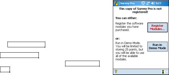
After Survey Pro is installed, the Standard Module must be registered for Survey Pro to be fully functional. If it is not registered, Survey Pro will only run in demo mode, which means all jobs will be limited to no more than 25 points, and if a job is stored on the data collector that exceeds this limit, it cannot be opened.
If you start Survey Pro and the standard module has not yet been registered, the screen shown here will open. Tap
the Register Modules… button to access the Register
Modules screen. To run in demo mode, simply tap
Run In Demo Mode .
To register your Modules, tap the Enter Registration
Code button.
4

Getting Started
Enter the registration code provided by your TDS dealer
in the Registration Code field and tap Register. This will
register all of the modules that you have purchased. If there are modules that you feel should be registered but are not, contact TDS tech support.
Add-on modules can also be purchased from your local TDS dealer to upgrade your TDS Survey Software. Upgrading involves simply registering the appropriate module using the same method as described above
If you want to register a particular module, access the
Register screen by tapping File , Register Modules from the Main Menu.
Contact your TDS dealer and give him your unique serial number that is displayed on this screen. He will give you a registration code for the module that you purchased.
Tap the Enter Registration Code button for the
appropriate module, enter the registration code in the
dialog box that opens and tap Register… . All the
features for the module that you purchased will now be available.
Note: You should keep a record of all registration codes purchased in case they need to be reentered at some point.
5
User’s Manual
Data Entry
Using a handheld device without a keyboard requires some adaptation but one can get very proficient when using all the shortcuts available to navigate around quickly. Even if you are already familiar with the Survey Pro software, reading this section can help you get the most from your handheld device.
Survey Pro offers several alternatives to input characters without a physical keyboard. These methods take the form of an overlay window, called Soft Input Panels (SIPs). You interact with a SIP through the touch screen. While you can get by using the standard SIPs, The Recon also provides a custom SIP called Recon Keyboard, which is optimized for Survey Pro.
Smart SIP
The Smart SIP is available when running Survey Pro and will automatically provide the user with the appropriate SIP when it is needed. The SIP can also be configured to automatically open when the cursor is inside an input field.
Enabling the Smart SIP
The Smart SIP is enabled by default, but if it has been disabled, you can re-enable it using the following steps:
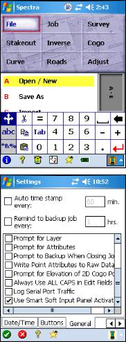
From the Main Menu, open the Job > Settings >
General screen.
Check the Use Smart Soft Input Panel Activation checkbox.
If the Smart SIP were not enabled, the user would need to click on the SIP icon on the taskbar to toggle the visibility of the SIP prior to entering data.
6

Getting Started
Using the Smart SIP
Whenever you tap in an edit field, the appropriate SIP will automatically open. The type of edit field where the cursor is placed determines the type of SIP that opens. The SIP will position itself so that it does not cover the edit field.
There are three types of edit fields:
•Point name edit fields: These default to the numeric SIP.
•Alphanumeric edit fields: such as Description, File Name, Layer Name, etc. These default to the alphanumeric SIP.
•Numeric edit fields: such as HI / HR, angles, distances, etc. These default to the numeric SIP.
The SIP will close when:
•You tap in a blank area of the dialog.
•You tap on another control, like a button or a list box.
•You switch to another tab page.
•The current dialog is closed or another dialog appears.
7

User’s Manual
Changing SIPs
While the cursor is in an input field, you can select a different SIP to use for entering text into that field and Survey Pro will remember your selection and open the new SIP whenever the cursor is placed into the same type of input field. The same behavior will occur if you switch between the alpha and numeric keyboards.
To select a different SIP, tap the up-arrow button next to the SIP icon. A list of all installed SIPs will open. Simply tap on the SIP you want to use.
Hardware Buttons
Survey Pro allows you to remap the function of the hardware buttons from a list of commonly used functions.
Some of the functions offered for button remapping include: Enter,
Escape, Tab, Quick Pick, Take Shot, etc. You can also use Page Up/Down to move between tab pages where applicable. See the Buttons Settings screen in the Reference Manual for more information on customizing the hardware buttons.
8
Getting Started
Angle and Time Conventions
Throughout the software, the following conventions are followed when inputting or outputting angles and time:
Azimuths
Azimuths are entered in degree-minutes-seconds format and are represented as DD.MMSSsss, where:
•DD One or more digits representing the degrees.
•MM Two digits representing the minutes.
•SS Two digits representing the seconds.
•sss Zero or more digits representing the decimal fraction part of the seconds.
For example, 212.5800 would indicate 212 degrees, 58 minutes, 0 seconds.
Bearings
Bearings can be entered in either of the following formats:
•S32.5800W to indicate south 32 degrees, 58 minutes, 0 seconds west.
•3 32.5800 to indicate 32 degrees, 58 minutes, 0 seconds in quadrant 3.
Time
When a field accepts a time for its input, the time is entered in hours- minutes-seconds format, which is represented as HH.MMSSsss where:
•HH One or more digits representing the hours.
•MM Two digits representing the minutes.
•SS Two digits representing the seconds.
9
User’s Manual
•sss Zero or more digits representing the decimal fraction part of the seconds.
10
Getting Started
Using Survey Pro
Tapping the screen with a stylus is the primary method for interaction with Survey Pro.
You can start Survey Pro by tapping the 
 icon, selecting Programs, then selecting Survey Pro.
Note: The proper way to exit Survey Pro is by selecting
File , Exit from the Main Menu. Exiting in this way
guarantees that the settings will get saved properly to the registry.
Once Survey Pro is started, the Survey Pro splash screen will open. Since Survey Pro requires a job to be opened when it starts, you will be prompted to open a recently opened job, an existing job, or to create a new job. The example below briefly explains how to create a new job so you can begin exploring the software.
1.Tap the New… button. The Create a New Job dialog box will open, which prompts you for a job name where the current date is the default name.
2.Either type in a new job name or accept the default name. Control points can optionally be used or imported from another existing job by checking the
Use or Import a Control File checkbox. (See Page 36 for more information on control files.) For this example, leave this unchecked and tap Next > to continue.
11

User’s Manual
3.Another screen will open where you select some of the job settings. Select the settings that you desire and tap Next > to continue.
Note: When creating a new job, it is important that the Units for Distances field be set to the correct units. This allows you to seamlessly switch between different units in mid-job, but problems can arise if these units are inadvertently set to the incorrect units when new data is collected.
4.Since all jobs must have at least one point to start with, the final screen displays the default point name and coordinates for the first point. Accept the default values by tapping Finish . This will create and store the new job. You are now ready to explore the software.
12
Getting Started
Navigating Within the Program
The starting point in Survey Pro, which appears once a job is open, is called the Main Menu, which is shown here. All the screens that are available in Survey Pro can be accessed starting from the Main Menu. Likewise, closing any screens that are open in Survey Pro will eventually take you back to the Main Menu.
The Main Menu consists of two main areas. The upper half of the screen contains a set of large buttons called main menu items. The lower half of the screen contains the submenu items that are associated with the selected main menu item.
When a main menu item is tapped, the corresponding submenu items will become available in the lower area. When a submenu item is tapped in the lower area, the corresponding screen will open. It is from these screens
where you do your work.
If a main menu item contains more submenu items than will fit on the screen, index card-style tabs are displayed on the right. Tapping these tabs will display additional submenu items.
The hardware keys can also be used to navigate within the Main Menu and any other Survey Pro screen. The highlighted rectangle displays the area of the screen that is currently active.
The bottom area of the Main Menu contains a set of icons that perform the tasks discussed below.
13

User’s Manual
Command Bar
The command bar is the bottom portion of each Survey Pro screen and it contains buttons that are appropriate for the current screen. All of the possible buttons are described below.
About Survey Pro 
Tapping this button from the Main Menu or selecting File
> About Survey Pro will open the About Survey Pro screen, which displays information on the version of Survey Pro that is installed.
The Hardware Information button is a shortcut to the
Windows System Information screen.
Online Help 
This button opens the online help, which allows you to access information for each screen similar to the information you would find in the reference manual.
14

Getting Started
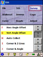
Surveying Mode 


The instrument icon indicates which collection mode the software is running in. There are three possible surveying modes:  Conventional,
  GPS, and
  Leveling. Tapping this icon will open a list of options to do any of the following:
•Switch to another instrument mode.
•Select a different instrument profile. (See the Instrument Settings screen in the Reference Manual for more information.)
•Quickly access the Instrument Settings screen. (See the Instrument Settings screen in the Reference Manual for more information.)
Map View 
This button will access the map view of the current job when it is tapped. The map view is available from many screens and is discussed in detail on Page 28.
Quick Pick 
The Quick Pick button will open a customizable list of routines. To quickly access a routine, just tap on it. See Page 24 for more information.
Battery Level 
The battery icon at the bottom of the Main Menu displays the condition of the data collector’s rechargeable battery. The icon has five variations depending on the level of charge remaining:  100%,
100%,  75%,
75%,  50%,
50%,  25%,
25%,  5% and
  charging.
Tapping the battery icon is a shortcut to the Microsoft Power Settings screen. You can get more information while viewing this screen by tapping  then
then  .
.
OK 
This button performs the desired action then closes the current screen.
15

User’s Manual
Cancel 
This button is red in color and closes the current screen without performing the action intended by the screen.
Close 
This button is green in color and closes the current screen.
Settings 
This button opens the Settings screen associated with the current screen.
GPS Status 


This is used to view the current status and access the settings for a GPS receiver when using the GeoLock feature (Page 165). It is only available from the Remote Control and Remote Shot screens when using a supported robotic total station.
16
Getting Started
Parts of a Screen
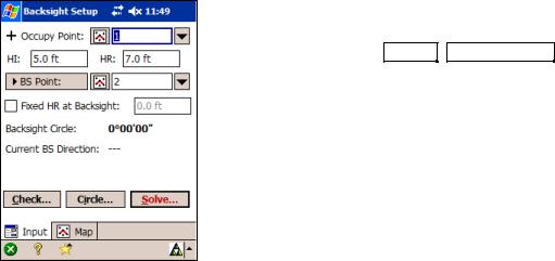
Many screens share common features. To illustrate some of these features, we will examine parts of the Backsight Setup screen, shown here. You can access the Backsight
Setup screen by selecting Survey , Backsight Setup from the Main Menu.
Input Fields
An input field is an area where a specific value is entered by the user. An input field consists of a label, which identifies the data that is to be entered in that field and a rectangular area with a white background, where the data is entered. A field must first be selected before data can be entered in it. You can select a field by tapping on its data area. When a field is selected, a dark border is drawn around it and a blinking cursor is inside the field.
Output Fields
Output fields only display information. These fields typically display values in bold text, do not have a special colored background, and the value cannot be changed from the current screen. For example, in the Backsight Setup screen, the Backsight Circle value is an output field.
17

User’s Manual
Power Buttons 
The Backsight Setup screen contains two power buttons. Power buttons are typically used to provide alternate methods of entering or modifying data in an associated field. To use a power button, simply tap it. Once tapped, a dropdown list will appear with several choices. The choices available vary depending on with which field the power button is associated. Simply tap the desired choice from the dropdown list.
Tapping the first power button in the Backsight Setup screen allows you to specify an occupy point using other methods or view the details of the currently selected point. You should experiment with the options available with various power buttons to become familiar with them.
Choose From Map Button 
The Choose From Map button is always associated with a field where an existing point is required. When the button is tapped, a map view is displayed. To select a point for the required field, just tap it from the map.
Note: If you tap a point from the map view that is located next to other points, another screen will open that displays all of the points in the area that was tapped. Tap the desired point from the list to select it.
18

Getting Started
Scroll Buttons Button.
When a button label is preceded with the symbol, it indicates that the button label can be changed. Each tap of the symbol will toggle through the various button label options and the corresponding field associated with it. For example, in the Backsight Setup screen, the backsight can be defined by a point or a direction by toggling the
scroll button between BS Point and BS Direction .
Special Point Symbols
Some field labels are preceded with a special symbol. For example, the Occupy Point field in the Backsight Setup screen is displayed as “+ Occupy Point” The plus symbol indicates that the occupy point is represented as a plus symbol when viewing it in the Map View. Other symbols are also used to represent other types of points.
Index Cards
Many screens have access to other screens that are still part of the original screen. The different screens are selected by tapping on various tabs, which look like the tabs of on index cards. The tabs can appear along the top of the screen or the right edge.
The Backsight Setup screen consists of two cards. One is titled Input, and the other is titled Map.
19

User’s Manual
Input Shortcuts
Distances and angles are normally entered in the appropriate fields simply by typing the value from the keypad, but there is a shortcut that can simplify the entry of a distance or angle.
If you want to enter the distance between two points in a particular field, but you do not know offhand what that distance is, you can enter the two point names that define that distance separated by a hyphen. For example, entering 1-2 in a distance field would compute the horizontal distance from Point 1 to Point 2. As soon as the cursor is moved from that field, the horizontal distance between the points will be computed and entered in that field.
An alternate method to using this shortcut is to tap the  power button, select Choose from map… and then tap the two points that define the distance that you want to enter. Once you tap
  from the Map View, the horizontal distance between the two tapped points will appear in the corresponding field.
Likewise, there is a similar shortcut to enter angles in fields that accept them. If you wanted to enter the angle, α, from the illustration shown here, you would simply enter 1-2-3 in the appropriate field. As soon as the cursor is moved from that field, the angle formed by the three points entered will be entered in that field. As with specifying a distance, you could also use the power button as described above and tap the points of the angle in the correct order.
Another shortcut can be used to enter distances with fractional inches (architectural units). Simply key in the feet, inches, and fractional inches where each value is separated by a space and the fraction is entered using a dash (-), or a forward slash (/). For example, to enter 3 feet, 6 and 3/32 inches, you would key in 3 6 3-32. Once the cursor leaves that field, the distance will automatically be converted to the appropriate decimal distance.
If working with distances under 1 foot, it is acceptable to exclude the feet value; for example “8 5-64” would be interpreted as 8 and 5/64 inches. Likewise, if entering a fractional distance under an inch, you would only enter the fractional inch.
The following details should be considered when using the above method to enter fractional inches:
1
2
α
 3
3
20
Loading...