


SP80
Table of contents
 Loading...
User Guide
SP80 GNSS Receiver
Legal Notices
©2014 Trimble Navigation Limited. All rights
reserved.
All product and brand names mentioned in this
publication are trademarks of their respective hold-
ers.
SP80 User Guide, Rev. A, December 2013.
Limited Warranty Terms and Conditions
Product Limited Warranty. Subject to the terms and
conditions set forth herein, Trimble Navigation Lim-
ited (“Trimble”) warrants that for a period of (1)
year from date of purchase this Spectra Precision
product (the “Product”) will substantially conform
to our publicly available specifications for the Prod-
uct and that the hardware and any storage media
components of the Product will be substantially
free from defects in materials and workmanship.
Product Software. Product software, whether built
into hardware circuitry as firmware, provided as a
standalone computer software product, embedded
in flash memory, or stored on magnetic or other me-
dia, is licensed solely for use with or as an integral
part of the Product and is not sold. The terms of the
end user license agreement govern the use of the
Product Software, including any differing limited
warranty terms, exclusions and limitations, which
shall control over the terms and conditions set forth
in the limited Product warranty.
Warranty Remedies. If the Product fails during the
warranty period for reasons covered by this limited
warranty and you notify us of such failure during
the warranty period, we will repair OR replace the
nonconforming Product with new, equivalent to
new, or reconditioned parts or Product, OR refund
the Product purchase price paid by you, at our op-
tion, upon your return of the Product in accordance
with our product return procedures then in effect.
Notices
Class B Statement - Notice to Users. This equip-
ment has been tested and found to comply with the
limits for a Class B digital device, pursuant to Part
15 of the FCC Rules. These limits are designed to
provide reasonable protection against harmful in-
terference in a residential installation. This equip-
ment generates, uses and can radiate radio
frequency energy and, if not installed and used in
accordance with the instructions, may cause harm-
ful interference to radio communication. However,
there is no guarantee that interference will not oc-
cur in a particular installation. If this equipment
does cause harmful interference to radio or televi-
sion reception, which can be determined by turning
the equipment off and on, the user is encouraged
to try to correct the interference by one or more of
the following measures:
• Reorient or relocate the receiving antenna.
• Increase the separation between the equip-
ment and the receiver.
• Connect the equipment into an outlet on a cir-
cuit different from that to which the receiver is
connected.
• Consult the dealer or an experienced radio/TV
technician for help.
Changes or modifications not expressly approved by
the manufacturer or registrant of this equipment
can void your authority to operate this equipment
under Federal Communications Commi ssion rules.
Canada
The digital apparatus does not exceed the Class B
limits for radio noise emissions from digital appara-
tus as set out in the radio interference regulations
of the Canadian Department of Communications.
Le présent appareil numérique n’émet pas de
bruits radioélectriques dépassant les limites
applicables aux appareils numériques de Classe B
prescrites dans le règlement sur le brouillage
radioélectrique édicté par le Ministère des
Communications du Canada.
Europe
This product has been tested and found to comply
with the requirements for a Class B device pursuant
to European Council Directive 89/336/EEC on
EMC, thereby satisfying the requirements for CE
Marking and sales within the European Economic
Area (EEA). These requirements are designed to
provide reasonable protection against harmful in-
terference when the equipment is operated in a res-
idential or commercial environment.
Notice to Our European Union Customers
For product recycling instructions and more infor-
mation, please go to http://www.spectrapreci-
sion.com/footer/weee-and-rohs/.
Recycling in Europe: To recycle Spectra Precision
WEEE (Waste Electrical and Electronic Equipment
products that run on electric power), call +31 497
53 24 30 and ask for the “WEEE Associate”. Or,
mail a request for recycling instructions to:
Tri mbl e E u ro pe B V
c/o Menlo Worldwide Logistics
Meerheide 45
5521 DZ Eersel, NL
Declaration of Conformity
We, Spectra Precision,
declare under sole responsibility that the product:
SP80 GNSS receiver
complies with Part 15 of FCC Rules.
Operation is subject to the following two condi-
tions:
(1) this device may not cause harmful interference,
(2) and this device must accept any interference
received, including interference that may cause
undesired operation.
Rechargeable Lithium-ion Batteries
This receiver uses one or two rechargeable Lithium-
ion batteries.
WARN ING - Do not damage the rechargeable Lithi-
um-ion batteries. A damaged battery can cause an
explosion or fire, and can result in personal injury
and/or property damage. To prevent injury or dam-
age:
• Do not use or charge the batteries if they ap-
pear to be damaged. Signs of damage include,
but are not limited to, discoloration, warping,
and leaking battery fluid.
• Do not expose the batteries to fire, high tem-
perature, or direct sunlight.
• Do not immerse the batteries in water.
• Do not use or store the batteries inside a vehi-
cle during hot weather.
• Do not drop or puncture the batteries.
• Do not open the batteries or short-circuit their
contacts.
WARN ING - Avoid contact with a rechargeable Lith-
ium-ion battery if it appears to be leaking. Battery
fluid is corrosive, and contact with it can result in
personal injury and/or property damage. To prevent
injury or damage:
• If a battery leaks, avoid contact with the bat-
tery fluid.
• If battery fluid gets into your eyes, immediate-
ly rinse your eyes with clean water and seek
medical attention. Do not rub your eyes!
• If battery fluid gets onto your skin or clothing,
immediately use clean water to wash off the
battery fluid.
WARN ING - Charge and use the rechargeable Lith-
ium-ion batteries only in strict accordance with the
instructions. Charging or using the batteries in un-
authorized equipment can cause an explosion or
fire, and can result in personal injury or/and equip-
ment damage. To prevent injury or damage:
• Do not charge a battery if it appears to be dam-
aged or leaking.
• USE EXCLUSIVELY the dual-battery charger
(P/N 61116-10) or the AC/DC power block
(model ADP-65JH AB, P/N 78650-SPN) to
charge the SP80 Lithium-ion batteries. See
instructions in this guide. These two devices
are part of the SP80 standard accessories list.
CHARGE THE BATTERIES ONLY IN THE
TEMPERATURE RANGE 0° to +40°C (32° to
104°F), at a maximum altitude of 2,000 me-
ters (6,562 feet).
• Discontinue charging a battery that gives off
extreme heat or a burning odor.
• Use the batteries only in Spectra Precision
equipment that is specified to use them.
• Use the batteries only for their intended use
and according to the instructions in the prod-
uct documentation.
Disposing of Rechargeable Lithium-ion Batteries
Discharge Lithium-ion batteries before disposing of
them. When disposing of batteries, be sure to do so
in an environmentally sensitive manner. Adhere to
any local and national regulations concerning bat-
tery disposal or recycling.
Receiver Use and Care
The receiver can withstand the rough treatment
that typically occurs in the field. However, the re-
ceiver is a high-precision electronic instrument and
should be treated with reasonable care.
CAUTION - Operating or storing the receiver out-
side the specified temperature range can damage
it. For more information, see Physical Specifica-
tions in this guide.
High-power signals from a nearby radio or radar
transmitter can overwhelm the receiver circuits.
This does not harm the instrument, but it can pre-
vent the receiver from functioning correctly. Do not
use the receiver within 400 meters (1312 feet) of
powerful radar, television or other transmitters.
Low-power transmitters such as those used in cell
phones and two-way radios do not normally inter-
fere with receiver operations.
For more information, contact your Spectra Preci-
sion distributor.
Bluetooth & Wifi Radios
The radiated output power of the wireless radios is
far below the FCC radio-frequency exposure limits.
Nevertheless, the wireless radios shall be used in
such a manner that the Spectra Precision receiver
is 20 cm or further from the human body.
The internal wireless radios operate within guide-
lines found in radio-frequency safety standards and
recommendations, which reflect the consensus of
the scientific community. Spectra precision there-
fore believes the internal wireless radios are safe for
use by consumers.
The level of energy emitted is far less than the elec-
tromagnetic energy emitted by wireless devices
such as mobile phones. However, the use of wire-
less radios may be restricted in some situations or
environments, such as on aircraft. If you are unsure
of restrictions, you are encouraged to ask for autho-
rization before turning on the wireless radios.
COCOM Limits
The US Department of Commerce requires that all
exportable GNSS products contain performance
limitations so that they cannot be used in a manner
that could threaten the security of the United
States.
The following limitation is implemented on the re-
ceiver: Immediate access to satellite measure-
ments and navigation results is disabled when the
receiver’s velocity is computed to be greater than
1000 knots, or its altitude is computed to be above
17,000 meters (59,055 feet). The receiver contin-
uously resets until the COCOM situation is cleared.
Technical Assistance
If you have a problem and cannot find the informa-
tion you need in the product documentation, con-
tact your local distributor. Alternatively, request
technical support using the Spectra Precision web-
site at www.spectraprecision.com.
Your Comments
Your feedback about the supporting documentation
helps us improve it with each revision. Email your
comments to documentation_feedback@spectra-
precision.com.

UHF Radios
Regulations and Safety. The receiver may be fitted
with an internal radio as an option. It can also be
connected to an external UHF radio.
Regulations regarding the use of Ultra High Frequen-
cy (UHF) radio-modems vary greatly from country to
country. In some countries, the UHF kit may be used
without obtaining an end-user license. Other coun-
tries require end-user licensing. For licensing infor-
mation, consult your local Spectra Precision dealer.
Before operating the receiver with the UHF kit, deter-
mine if authorization or a license to operate the UHF
kit is required in your country. It is the end-user’s re-
sponsibility to obtain an operator’s permit or license
for the location or country of use.
Expos ure to RF energy i s an important safety consid-
eration. The FCC has adopted a safety standard for
human exposure to radio-frequency electromagnetic
energy.
Proper use of this radio modem results in exposure
below government limits. The following precautions
are recommended:
• DO NOT operate the transmitter when someone
is within 20 cm (7.8 inches) of the antenna.
• DO NOT collocate (place within 20 cm) the ra-
dio antenna with any other transmitting device.
• DO NOT operate the transmitter unless all RF
connectors are secure and any open connectors
are properly terminated.
• DO NOT operate the equipment near electric
blasting caps or in an explosive atmosphere.
• All equipment must be properly grounded ac-
cording to Spectra Precision installation in-
structions for safe operation.
• All equipment should be serviced only by a qual-
ified technician.

Table of Contents
About Spectra Precision SP80 .............................................................1
SP80 Packout.....................................................................................2
Standard Accessories.............................................................2
Optional Accessories..............................................................3
Other Optional Accessories .....................................................4
Discover Your New Equipment .............................................................5
Front Panel ...........................................................................5
Bottom View..........................................................................6
Right-Side View.....................................................................7
Left-Side View.......................................................................8
Phase Center Location ...........................................................8
Height Mark..........................................................................9
Special Key Combinations ....................................................10
Screen Illumination & Buzzer................................................10
Using SP80 for the First Time ............................................................11
Charging the Batteries..........................................................11
Inserting the Batteries..........................................................12
Inserting Cards....................................................................13
Setting up the Receiver........................................................14
Running a Survey ................................................................14
Ending the Survey ...............................................................15
Front Panel Displays..........................................................................16
Welcome Screen..................................................................16
General Status ...................................................................17
Memory/SD Card..................................................................19
Receiver Identification ........................................................19
Position Solution .................................................................19
Devices...............................................................................20
ATL Recording Screen .........................................................21
Memory Management ..........................................................22
Power Off Screen.................................................................22
Raw Data Recording Screen..................................................22
Monitoring Batteries..........................................................................23
Conventions Used................................................................23
Possible Battery Statuses in the Field....................................24
Possible Battery Statuses With AC/DC Power Block Used.........25
Possible Error Statuses ........................................................26
Remote Battery Monitoring ...................................................27
Lithium-Ion Battery Storage..................................................27
Rover Setup .....................................................................................28
Network Rover.....................................................................28
Rover in CSD Mode..............................................................28
Rover With Radio.................................................................28

Base Setup....................................................................................... 29
Network Base ......................................................................29
Base in CSD Mode ...............................................................29
Base With Radio ..................................................................29
Internal vs. External Power Source.........................................30
Recording/Downloading GNSS Raw Data ............................................ 31
Data Recording Flowchart.....................................................31
Step-by-Step Procedure........................................................31
Downloading Raw Data Files .................................................34
Charging Batteries - Using External Power .........................................35
Batteries Vs. External Power Source.......................................35
Charging Batteries, Scenario #1............................................35
Charging Batteries, Scenario #2............................................36
Using Cable P/N 59044-10-SPN from the Office Power Kit..37
Using Cable P/N 95715 from the Field Power Kit................37
Anti-Theft Protection......................................................................... 38
Theory of Operation..............................................................38
Purpose...........................................................................38
Enabling/Disabling the Anti-Theft Protection.......................38
How the Receiver Operates With the Anti-Theft On ..............38
What the Anti-Theft Protection Does Initially.......................38
What Events Will Trigger a Theft Alarm? .............................39
What Will Happen When a Theft is Detected?......................39
What if the Thief Removes the Batteries? ...........................39
Disabling Anti-Theft Before Turning Off the Receiver ...........40
Lost your Anti-Theft Password?..........................................40
The Theft Alarm is Part of the Level-1 Alarms List...............40
Using the Anti-Theft Protection in Survey Pro ........................41
Alerts Tab........................................................................41
Managing Contacts and Notifications .................................42
Enabling/Disabling the Anti-Theft Protection.......................43
Using the Anti-Theft Protection in FAST Survey .....................44
Using the UHF Kit Option ................................................................... 46
Installing the UHF Module into the Receiver ..........................47
Configuring the UHF Module.................................................48
Completing Rover Radio Setup..............................................49
Completing Base Radio Setup With External UHF Antenna ......50
Completing Base Radio Setup With Internal UHF Antenna.......51
Technical Specifications................................................................... 52
GNSS Characteristics...........................................................52
Real-Time Accuracy (RMS) ...................................................52
Real-Time Performance........................................................53
Post-Processing Accuracy (RMS)...........................................53
Data Logging Characteristics.................................................53
Physical Characteristics........................................................53
Standard & Optional System Components ..............................55
Data Collectors and Software ................................................55
Appendix......................................................................................... 56
USB Connection ..................................................................56
Upgrading Receiver Firmware................................................56
Restoring Factory Settings ....................................................58
Alerts .................................................................................59

English
1
About Spectra Precision SP80
The Spectra Precision SP80 is a new-generation GNSS
receiver that combines decades of GNSS RTK technology
with a revolutionary new GNSS processing. Featuring the new
240-channel “6G” chipset, the SP80 system is optimized for
tracking and processing signals from all GNSS constellations.
In addition, SP80 is the most connected GNSS receiver in
the industry. It is the first to offer a unique combination of
integrated 3.5G cellular, WiFi and UHF communications with
SMS, email and anti-theft features.
These powerful capabilities, packaged in an ultra-rugged and
cable-free housing with unlimited operation time (hot-
swappable batteries) make SP80 an extremely versatile
turnkey solution.
The key features of the SP80 are:
• New 240-channel 6G chipset
• Z-Blade GNSS-centric technology
• 3.5G cellular modem
• Optional integrated TRx UHF radio
• Built-in Bluetooth and WiFi communication
• SMS and e-mail alerts
• Anti-theft technology
• Hot-swappable batteries
• 2-GB internal memory
English
2
SP80 Packout
NOTE: Spectra Precision reserves the right to make changes
to the lists of items provided below without prior notice.
Standard
Accessories
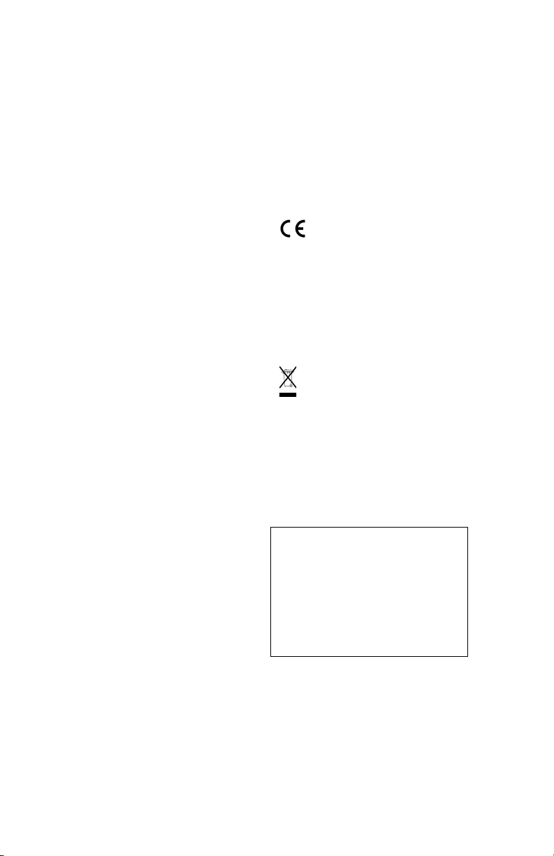
The SP80 GNSS Single Receiver Kit (P/N 94334-00)
consists of the following items.
(1) When applicable, the items part of the standard packout may be ordered
separately as spare parts, using the P/Ns specified in this column.
NOTE: The SP80 User Guide may be downloaded from:
www.spectraprecision.com/products/gnss-surveying/SP80/
Item Picture Spare Part (1)
SP80 GNSS receiver (Not Applicable)
Li-Ion Battery, 2.6 Ah, 7.4 V, 19.2 Wh
(Qty: 2)
92600-10 (one battery)
Dual Li-Ion Battery Charger (does not
include AC/DC power supply and
cable)
6111 6-1 0
AC/DC Power Block, 65 W, 19 V,
3.42 A, 100-240 VAC
78650-SPN
Power Cord Kit (four types) for use with
AC/DC Power Block
78651-SPN
Tape Measure, 3.6 m (12 feet) 93374
Pole Extension, 7 cm, for use on tripod 88400-50-SPN
USB-to-Mini Universal Cable 67901-11
Universal Hard Case, including large,
soft bag for field transport
802142-02
Product Software and Documentation
Leaflet, Quick Start Guide and Anti-
Theft Technology Adhesive Sticker.
(Not Applicable)
English
3
Optional
Accessories
Three different kits specific to the SP80 are available as
optional accessories.
(1) When applicable, the items part of these three SP80-specific kits may be
ordered separately as spare parts, using the P/Ns specified in this column.
(2) DOES NOT include the UHF antenna. See other optional accessories
below.
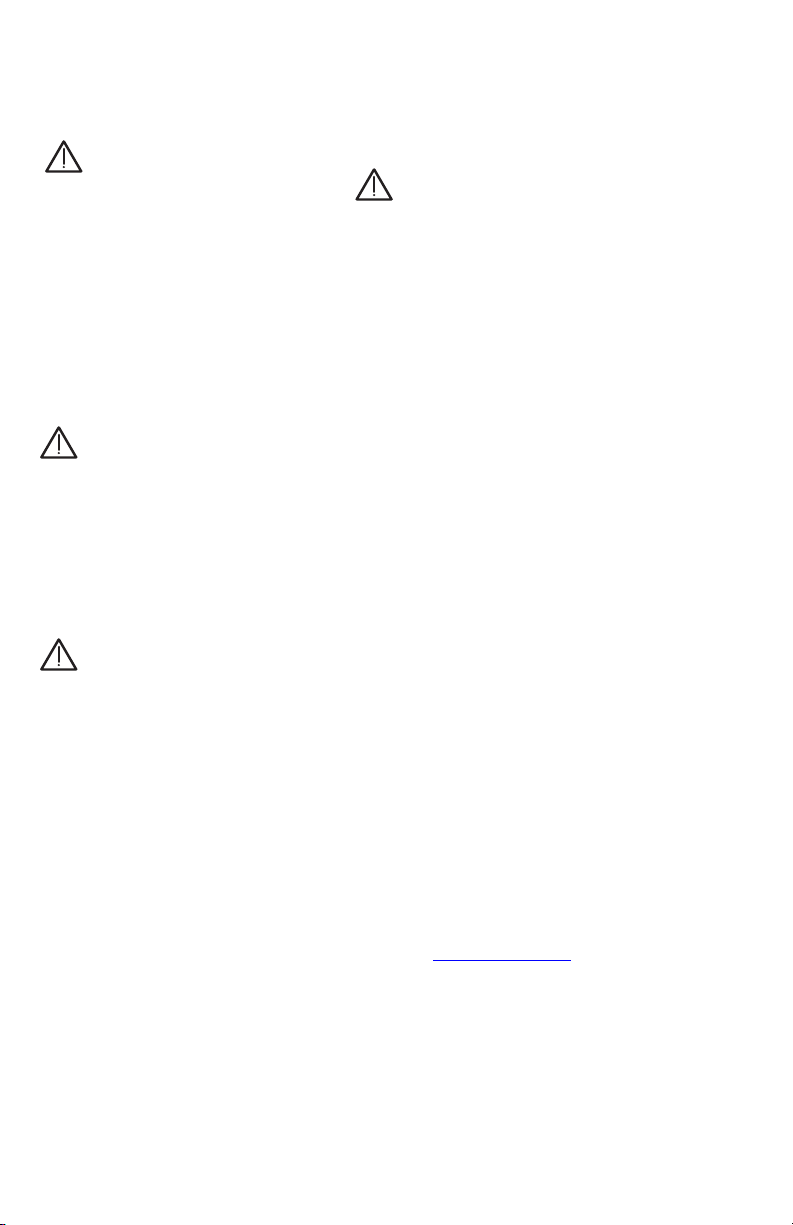
Item Picture Spare Part (1)
SP80 UHF Kit P/N 92673-00 (2):
UHF Module (Not Applicable)
Base Pole Extension, 25 cm (9.5”) long, with
oblong aperture
95672
Rover Range Pole, 2 m (6.5 ft) long, fiber-
glass, two parts, with specific tapping on top
part
89937-10
Soft Bag for Range Pole 95860
T25 Torx Screwdriver, “L” shaped (Not Applicable)
SP80 Field Power Kit P/N 94335:
Power cable, 0.6 m, 7P Lemo to SAE 95715
Power cable, 1.8 m, SAE to battery clips 83223-02-SPN
SP80 Office Power Kit P/N 94336:
Power/Data cable, 1.5 m, DB9-f to OS/7P/M
to SAE
59044-10-SPN
Adapter cable, 0.15 m, SAE to DC socket
(2.1 mm)
88769-SPN
RS232-to-USB adapter cable 90938-SPN
English
4
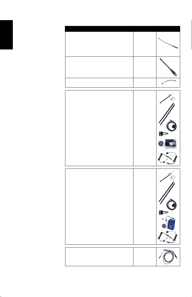
Other Optional
Accessories
Item Ordering P/N: Picture
UHF whip antenna, Procom, half-wave, with
TNC adapter:
• 410-430 MHz
• 430-450 MHz
• 450-470 MHz
C3310190
C3310196
C3310188
UHF whip antenna, ¼ wave, with TNC adapter:
• 410-430 MHz
• 430-470 MHz
67410-12
67410-11
Coaxial adapter cable (for use with P/N 95672) 96845
ADL Vantage Pro Accessories Kit. Choose
P/N according to UHF band used:
• 450-470 MHz
• 430-450 MHz
• 410-430 MHz
The kit includes the following items:
• Unity-gain antenna (compatible with chosen
band, see above)
• Range pole mount
• Tripod mount system
• HPB-Battery bag with cables (specific to
ADL Vantage Pro)
• HPB-Programming cable
(ADL Vantage Pro unit NOT included in the kit.)
87400-10
87400-20
87410-10
ADL Vantage Accessories Kit. Choose P/N
according to UHF band used:
• 450-470 MHz
• 430-450 MHz
• 410-430 MHz
The kit includes the following items:
• Unity-gain antenna (compatible with chosen
band, see above)
• Range pole mount
• Tripod mount system
• HPB-Battery bag with cables (specific to
ADL Vantage)
• HPB-Programming cable
(ADL Vantage unit NOT included in the kit.)
87330-10
87330-20
87310-10
Y cable, receiver-to-PacCrest HPB & Battery,
3.0 m (OS7P to 1S5P)
PCC-A02507
English
5
Discover Your New Equipment
Take a few minutes to discover your new SP80.
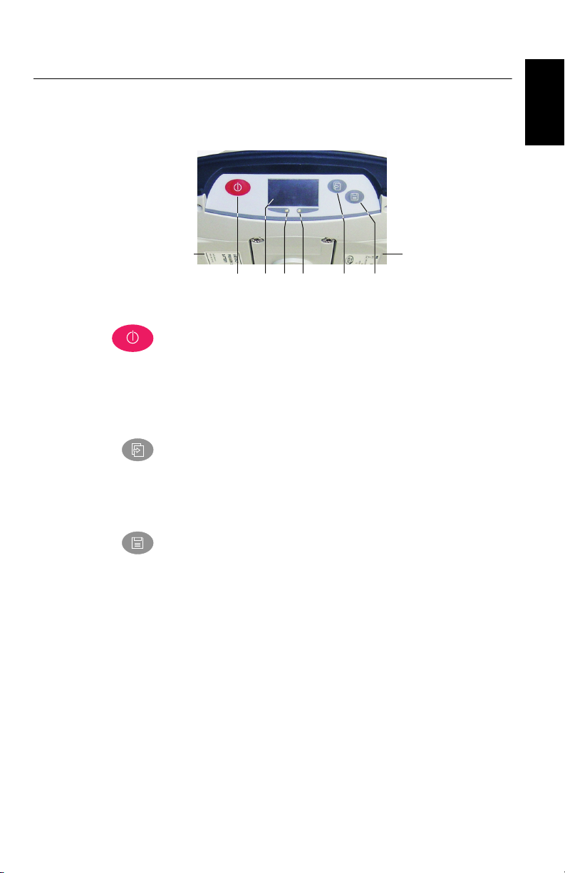
Front Panel
• [1]: Power button. Hold the button depressed for about
two seconds to turn on or off the receiver.
• [2]: Display screen
• [3]: Battery A LED indicator.
• [4]: Battery A compartment.
• [5]: Battery B LED indicator.
• [6]: Battery B compartment.
• [7]: Scroll button. Press this button to scroll through all
the display functions (including alarm screens if any).
Also used to accept or reject prompts in some particular
contexts.
• [8]: Log button. From the memory screen, press this
button to start or stop GNSS raw data recording. From all
other screens, pressing this button takes you back to the
General Status screen. Also used to accept or reject
prompts in some particular contexts.
NOTE: Pressing these buttons simultaneously gives
access to special receiver functions. See all the possible
combinations in Special Key Combinations on page 10.
[1] [2] [3] [5]
[4] [6]
[7] [8]
English
6
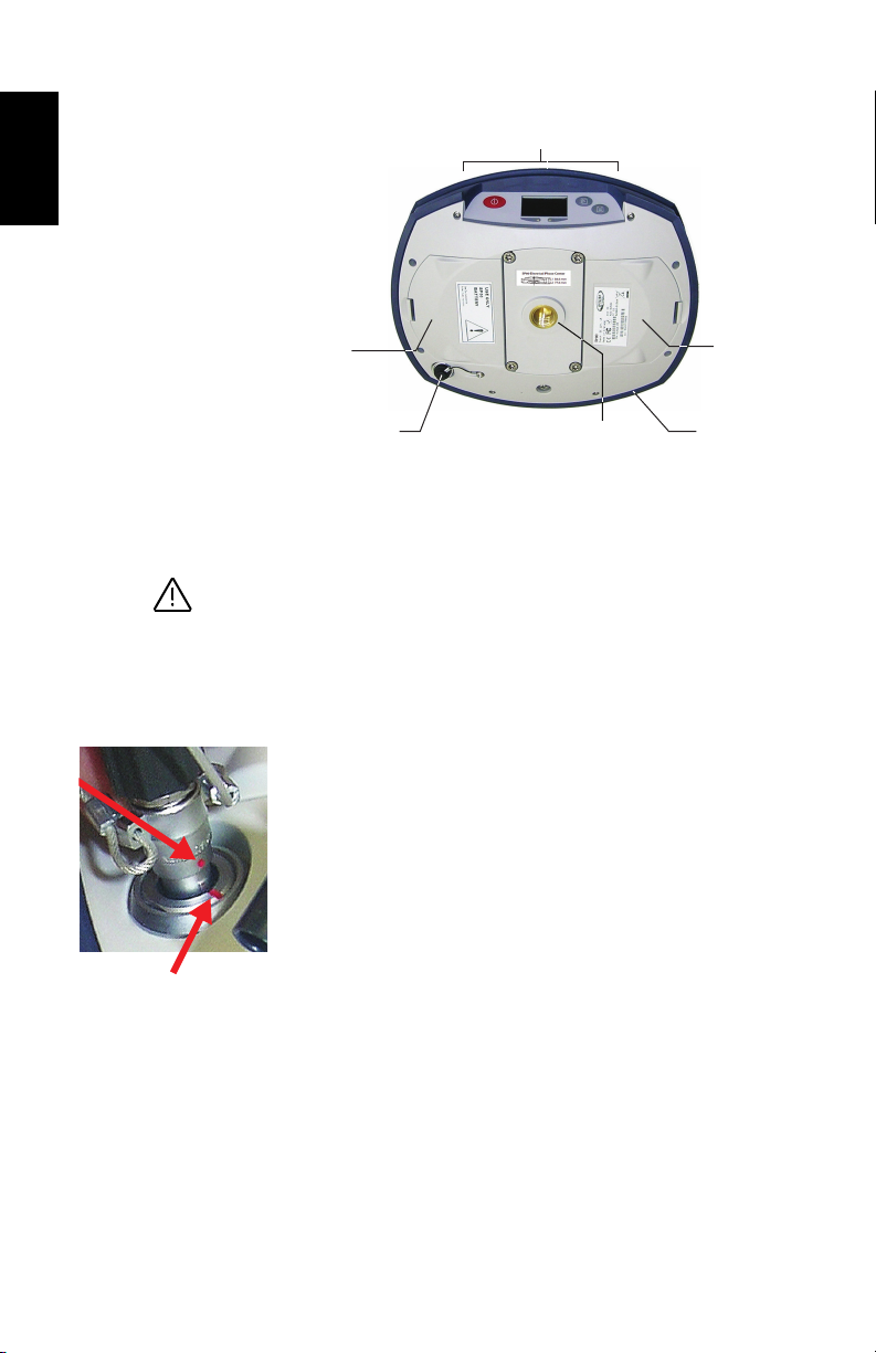
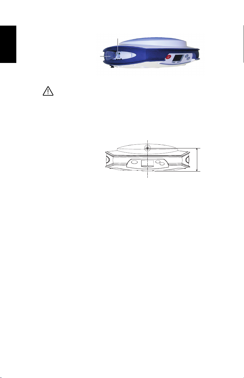
Bottom View
• [7]: Front panel (see details above)
• [8]: Battery A compartment trapdoor
• [9]: Battery B compartment trapdoor
CAUTION - THE TWO TRAPDOORS SHOULD BE OPENED
ONLY FOR INSERTING OR REMOVING BATTERIES. THE
REST OF THE TIME, PLEASE ALWAYS KEEP THEM
FULLY CLOSE TO PRESERVE WATERTIGHTNESS.
• [10]: Power/data connector (DC input + RS232 serial port
A). The connector socket is protected by a black rubber
cap attached to the receiver case. Always keep the
protection cap on when the connector is not used. This
cap is a non-polarized one.
IMPORTANT: When you connect a cable to that connector,
be sure you align the red markings (a red dot on the plug,
a red line on the socket) before pushing the Lemo plug in.
Conversely, when it’s time to disconnect the Lemo plug,
please use the attached metal strap to pull the plug out.
• [11]: 5/8” threaded insert. This part is securely mounted
on a removable plate, thus making up an assembly that
can be replaced with a UHF module (optional accessory)
fitted with its own, specific threaded hole and central
coaxial socket for antenna connection (see Using the UHF
Kit Option on page 46).
• [12]: Shock absorber making up a robust protection belt
for the receiver against drops to the ground. The shock
absorber houses two flaps for access to two card slots and
to a USB connector. The height mark is also nested in the
shock absorber. See below.
[7]
[9]
[10] [11]
[8]
[12]
English
7
Right-Side View
• [13]: SD card holder. An SD Card is a removable memory
extension that can be used to:
– Record GNSS raw data
– Copy G-files from the internal memory
– Or install firmware upgrades
Maximum capacity according to SDHC standard: 32 GB
The SD Card should be inserted into the receiver with its
label side oriented downward (pins upward).
• [14]: Standard (Mini) SIM card holder. A SIM card is
required to operate the internal cell modem when the
receiver is used in Direct IP, NTRIP or CSD. Please
contact your Internet Service Provider (ISP) to get the SIM
card you need.
The SIM card should be inserted into the receiver with its
label side oriented downward (visible chip upward).
WARNING - MAKE SURE YOU INSERT THE SIM CARD
INTO THE SIM CARD HOLDER AND NOT ELSEWHERE.
• [15]: Rubber flap protecting the SD card and SIM card
holders. To preserve watertightness, ALWAYS KEEP FULLY
CLOSE when you don’t need to access the card slots.
[15]
[13] [14]
English
8
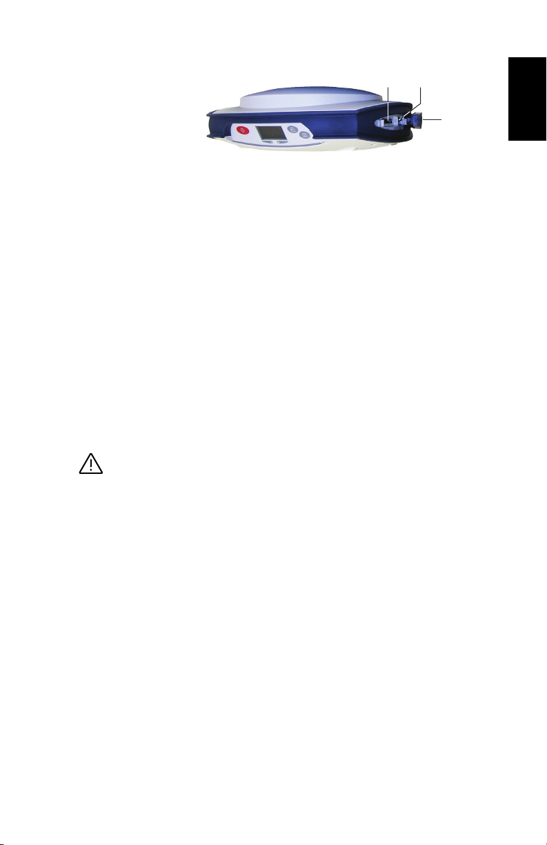
Left-Side View
• [16]: Rubber flap protecting the USB connector. To
preserve watertightness, ALWAYS KEEP FULLY CLOSE
when you don’t need to use the USB port.
• [17]: USB connector emulating standard RS232 serial
port (port B). For use in troubleshooting only.
Phase Center
Location
See diagram below. These are relative measurements.
The field software usually calculates the real height of the
instrument, based on the location of the L1 phase center.
Whether you provide a vertical or slant measurement of the
antenna base (ARP), the field software you are using should
be able to deduce the real height of the instrument, using the
pre-loaded dimensional parameters (antenna radius, etc.)
specific to the model of GNSS antenna used.
In the case of a slant measurement, the software will also use
the radius of the antenna to determine the instrument height.
[16]
[17]
L1 84.6 mm
L2 77.6 mm
English
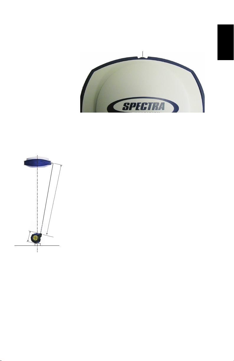
9
Height Mark The height mark ([18]) is nested on the shock absorber
diagonally to the front panel.
When the receiver is mounted on a tripod – for use as a base
for example – making a slant measurement to determine the
instrument height is often more convenient than making a
vertical measurement from the ground mark to the antenna
base.
In this case, the height mark can be used to hook the measure
tape (standard accessory) so you can unroll the tape down to
the ground mark and conveniently measure the distance
between these two points. However because the housing of
the measure tape is inserted in the path between the two
points, you should make the following correction to obtain the
real value of slant measurement:
Slant Measurement = Measured Distance + Delta L
Where “Delta L” is the length of the tape measure housing.
Delta L= 0.073 m or 0.2396 ft (2 7/8 inches), as mentioned on the housing.
When the field software requests your input to determine the
instrument height, you will then choose to enter the slant
measurement, rather than the vertical one. The software will
then be able to deduce the real height of the instrument from
the known dimensional parameters of the antenna and the
slant measurement you will have entered.
[18]
73 mm
0.2396 ft
Measured distance

English
10
Special Key
Combinations
The SP80 has three different key combinations requiring that
the receiver be initially turned off. See table below for details.
Screen
Illumination &
Buzzer
Screen illumination is automatically turned off if no button
has been pressed for 10 minutes of receiver operation. The
screen will then become entirely blank.
Screen illumination will be reactivated through one of the
following actions or events:
• By pressing shortly on the Log or Scroll button, which will
then recover their usual functions,
• On inserting an SD Card into the receiver,
• On occurrence of an alarm.
The buzzer can be heard in the following cases:
• When your data collector establishes a Bluetooth
connection with the receiver,
• On occurrence of an alarm.
Key combination Function
+
(Power + Scroll buttons)
Starts a firmware upgrade sequence from the
file stored in the SD Card.
+
(Power + Log buttons)
Enters the Service mode in which the UHF
module, if any, is temporarily connected to the
receiver’s serial port A for radio settings.
Refer to Configuring the UHF Module on
page 48.
+ +
(Power + Scroll + Log buttons)
Restores factory settings (see list in Restoring
Factory Settings on page 58).
English
11
Using SP80 for the First Time
WARNING - This receiver uses one or two rechargeable
Lithium-ion batteries. To avoid personal injury or equipment
damage, make sure that you read and understand the safety
information at the front of this guide.
The batteries are shipped partially charged. Depending on the
time elapsed since then, the remaining charge may be even
less. For this reason, you should first recharge the batteries
completely before first use. (See warnings and safety
information at the front of this guide.)
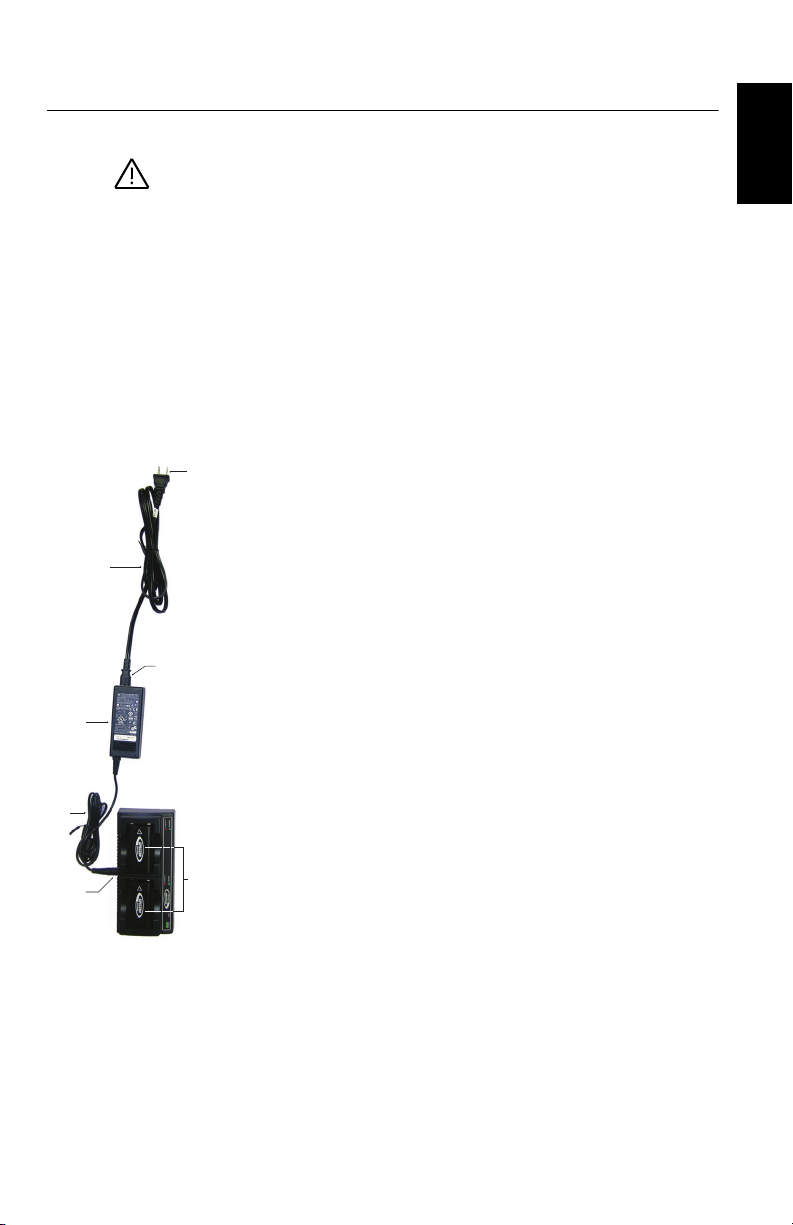
Charging the
Batteries
1. Set up the battery charger as explained:
– Connect the output cable ([1]) of the AC/DC power
block ([2]) to the battery charger input ([3]).
– Choose the power cord ([4]) that is suitable for your
country.
– Connect the end of the power cord to the AC/DC block
input ([5]), and the other to a power outlet ([6]). This
powers up the battery charger, causing the POWER
LED to turn solid green.
2. Insert the two batteries ([7]) onto the battery charger (give
the right orientation to the battery). For each battery, the
CONTACT LED will turn solid orange when the battery is
detected. The CHARGE LED will start blinking green at a
fast rate to indicate that the battery is being charged.
3. The batteries charge one after the other. This will take a
few hours. When a battery reaches full charge, the
corresponding CHARGE LED turns solid green.
4. Remove the batteries from the charger when both fully
charged.
NOTE: The batteries may be left on the charger for an
indefinite period of time without causing any damage to
the charger or the batteries.
[1]
[2]
[3]
[4]
[5]
[6]
[7]
English
12
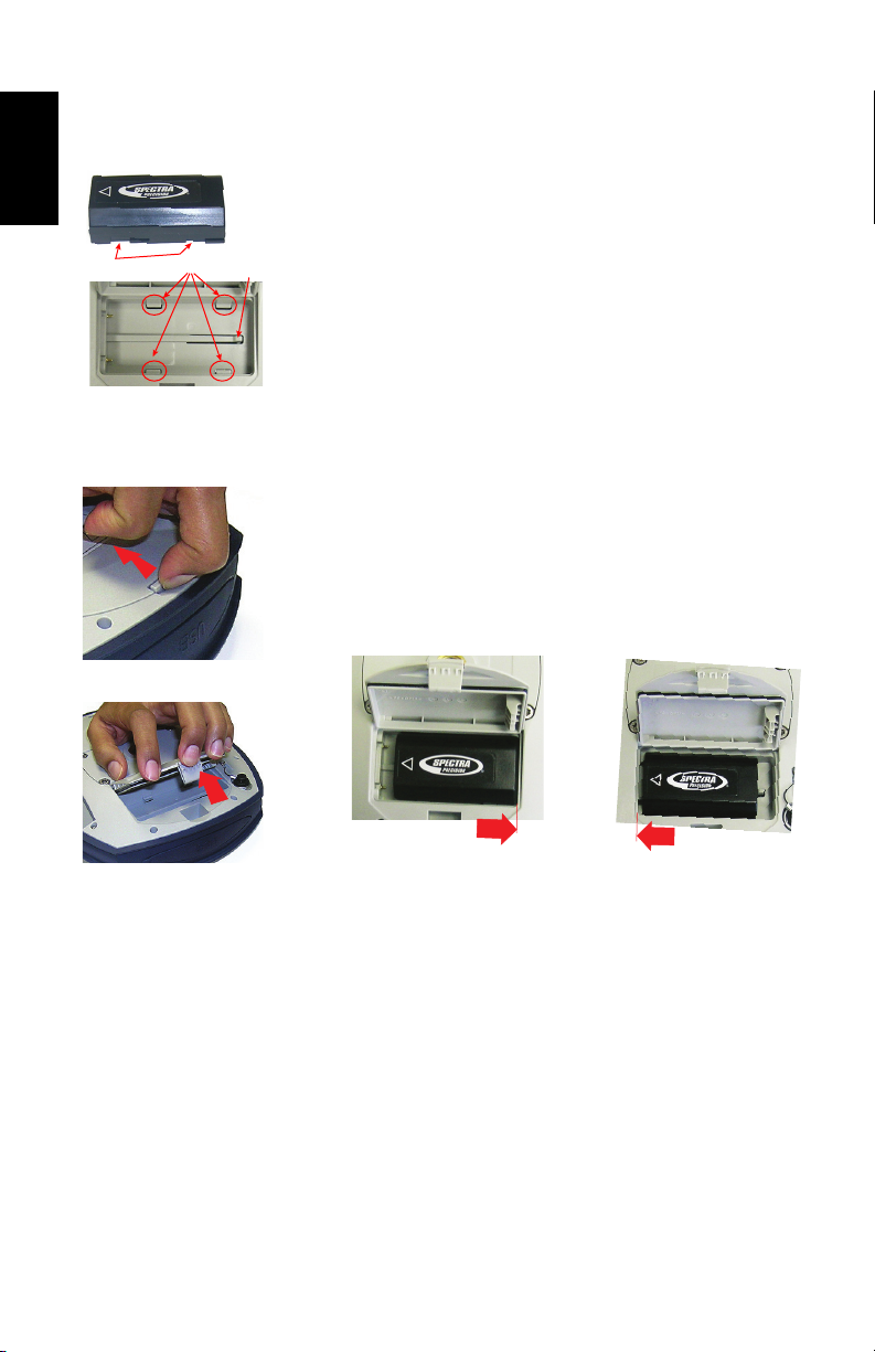
Inserting the
Batteries
Each battery is fitted with four recesses, two on each side
(see [8]).
These allow you to slide the battery into tabs located at the
bottom of the compartment (see [9]).
Once the battery is fully inserted, a stop mechanism ([10]) is
released by the battery to secure the electrical connection to
the receiver (this mechanism prevents the battery from
moving longitudinally).
The combination of these two mechanisms (slide + stop) will guarantee a
secure electrical connection to the receiver in all circumstances.
The two battery compartments are accessible from
underneath the receiver. Follow this procedure to insert a
battery into its compartment:
1. Turn the receiver upside down.
2. With a finger, push the snap-in hook inward to unlock the
trapdoor (see [11]), then pull it open (see [12]).
3. Give the right orientation to the battery, prop it against the
right inner side of the compartment (see [13]), then push
the battery in so that it fits into the four tabs.
4. Push the battery fully to the left (see [14]). This releases
the stop mechanism underneath the battery.
5. Close the trapdoor: It is good practice to use your two
thumbs pushing thoroughly from the two corners of the
trapdoor. By doing this, you will lock the snap-in hook
properly and you will make the battery compartment fully
waterproof.
6. Put back the receiver the right way up.
When later the receiver is placed on top of a pole, you will be able to safely
remove/replace a discharged battery (it won’t drop when you open the
compartment) while the receiver continues to operate normally, tacking
satellites, being powered from the other battery.
NOTE: The batteries will be used one after the other. The
receiver will determine which battery should be used first.
[8]
[9]
[10]
[11]
[12 ]
[13]
[14]
English
13
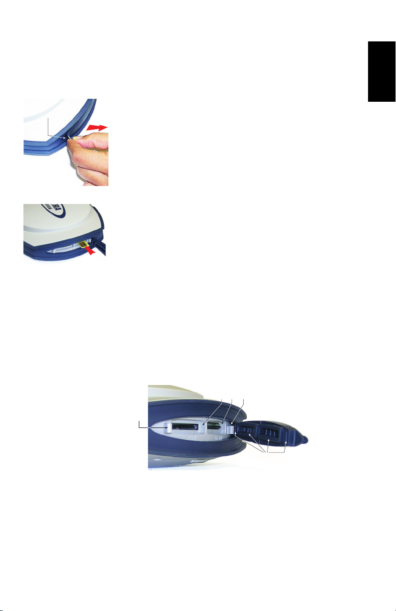
Inserting Cards A SIM card is needed to operate the internal modem when the
receiver is used in Direct IP, NTRIP or CSD mode.
You may also want the receiver to record GNSS raw data on
an SD card rather than in its internal memory.
In either case, insert the card through the procedure
described below:
1. Open the rubber flap with the “SD” and “SIM” markings
(on the right), pulling its tongue gently to the right. The
tongue is that small part protruding from one end of the
flap ([15]).
2. Turn the card upside down (label side oriented downward)
(see SIM card in [16]), then push it in until you hear a
click.
WARNING - PLEASE MAKE SURE YOU INSERT THE SIM
CARD INTO THE SIM CARD HOLDER AND NOT
ELSEWHERE.
3. Put the rubber flap back in place. This is a five-step
operation to be observed with care. The inner side of the
flap is fitted with molded parts (see [17]) that are
intended to fit into the card slots. Starting from the flap
hinge, these should be inserted successively into:
– The block the closest to the hinge ([18])
– The SIM card holder ([19])
– The SD card holder ([20])
– The second block ([21])
– Then run a thumb along the flap, starting from the
hinge and all the way to the other end, exerting
pressure as many times as necessary to make sure the
flap is thoroughly inserted.
[15]
[16]
[17]
[18][19][20]
[21]

English
14
NOTE 1: If you only need to access the SD card holder, you
may half-open the rubber flap. To do this, place three fingers
on the area marked “SIM” on the flap while grasping the
tongue to open the flap halfway (see [22]).
NOTE 2: To remove a SIM or SD card, simply push the card
a little bit further in causing the lock mechanism to be
released (a click can be heard). Then release the card, which
will then be automatically ejected.
Setting up the
Receiver
1. Mount the receiver and data collector on a range pole
(rover), or a tripod (base).
2. Measure and write down the vertical or slant distance from
the ground mark to respectively the lower part of the
receiver (ARP) (rover) or to the height mark (base). This
measurement will be required by your field software in a
further step.
3. Turn on the SP80 by holding depressed for about
2 seconds until the screen lights up. The status LED of
the battery being used turns solid green. Let the receiver
boot.
4. Meanwhile, turn on the data collector and run your field
software.
Running a Survey 1. Follow the instructions provided by your field software to
use the SP80 as desired (rover or base). The receiver will
beep when a Bluetooth connection is established with the
data collector.
2. Start your survey job when ready.
3. From time to time, take a look at the battery LEDs on the
front panel. As long as the two LEDs are solid green, that
means the first battery used has enough energy left to
operate the receiver.
When the LED corresponding to the first battery used
starts blinking green – first at a slow rate (1 sec), then at
a faster rate (5 flashes a second) – that will mean the
battery is too low and power will soon switch automatically
to the other battery.
Note that there won’t be any disruption in receiver
operation when passing from the low to the fresh battery.
There won’t be any disruption either if you replace the low
battery with a new fresh one. This third battery will power
the receiver later when the second battery gets in turn too
low.
[22]

English
15
Ending the Survey 1. After your field survey is complete, hold depressed
for about 2 seconds to turn off the SP80.
2. Don’t forget to charge the batteries at the end of your day.
Batteries will charge overnight.
NOTE: Need to download raw data files from the receiver?
Refer to Downloading Raw Data Files on page 34.
Loading...