


SURVEY PRO
for Windows® CE
GPS User’s Manual
2002 Tripod Data Systems, Inc.
All Rights Reserved
GPS User’s Manual
TRIPOD DATA SYSTEMS SOFTWARE LICENSE AGREEMENT
IMPORTANT: BY OPENING THE SEALED MEDIA PACKAGE, YOU ARE AGREEING TO BE BOUND BY THE TERMS AND CONDITIONS OF THE LICENSE AGREEMENT AND LIMITATIONS OF LIABILITY ("Agreement"). THIS AGREEMENT CONSTITUTES THE COMPLETE AGREEMENT BETWEEN YOU AND TRIPOD DATA SYSTEMS, INC. ("Licensor"). CAREFULLY READ THE AGREEMENT AND IF YOU DO NOT AGREE WITH THE TERMS, RETURN THE UNOPENED MEDIA PACKAGE AND THE ACCOMPANYING ITEMS (including written materials and binders or other containers) TO THE PLACE WHERE YOU OBTAINED THEM FOR A FULL REFUND.
LICENSE. LICENSOR grants to you a limited, non-exclusive license to (i) install and operate the copy of the computer program contained in this package ("Program") on a single computer (one central processing unit and associated monitor and keyboard) and (ii) make one archival copy of the Program for use with the same computer. LICENSOR retains all rights to the Program not expressly granted in this Agreement.
OWNERSHIP OF PROGRAMS AND COPIES. This license is not a sale of the original Program or any copies. LICENSOR retains the ownership of the Program and all subsequent copies of the Program made by you, regardless of the form in which the copies may exist. The Program and accompanying manuals ("Documentation") are copyrighted works of authorship and contain valuable trade secrets and confidential information proprietary to LICENSOR. You agree to exercise reasonable efforts to protect LICENSOR'S proprietary interest in the Program and Documentation and maintain them in strict confidence.
USER RESTRICTIONS. You may physically transfer some Programs from one computer to another provided that the Program is operated only on one computer. Other Programs will operate only with the computer that has the same security code and cannot be physically transferred to another computer. You may not electronically transfer the Program or operate it in a time-sharing or service bureau operation. You agree not to translate, modify, adapt, disassemble, de-compile, or reverse engineer the Program, or create derivative works based on the Program or Documentation or any portions thereof.
TRANSFER. The Program is provided for use in your internal commercial business operations and must remain at all times upon a single computer owned or leased by you. You may not rent, lease, sublicense, sell, assign, pledge, transfer or otherwise dispose of the Program or Documentation, on a temporary or permanent basis, without the prior written consent of LICENSOR.
TERMINATION. This License is effective until terminated. This License will terminate automatically without notice from LICENSOR if you fail to comply with any provision of this License. Upon termination you must cease all use of the Program and Documentation and return them, and any copies thereof, to LICENSOR.
GENERAL. This License shall be governed by and construed in accordance with the laws of the State of Oregon, United States of America.
LIMITED WARRANTIES AND LIMITATION OF LIABILITY
LICENSOR grants solely to you a limited warranty that (i) the media on which the Program is distributed shall be substantially free from material defects for a period of NINETY (90) DAYS, and (ii) the Program will perform substantially in accordance with the material descriptions in the Documentation for a period of NINETY (90) DAYS. These warranties commence on the day you first obtain the Program and extend only to you, the original customer. These limited warranties give you specific legal rights, and you may have other rights, which vary from state to state.
Except as specified above, LICENSOR MAKES NO WARRANTIES OR REPRESENTATIONS, EXPRESS OR IMPLIED, REGARDING THE PROGRAM, MEDIA OR DOCUMENTATION AND HEREBY EXPRESSLY DISCLAIMS THE WARRANTIES OF MERCHANTABILITY AND FITNESS FOR A PARTICULAR PURPOSE. LICENSOR does not warrant the Program will meet your requirements or that its operations will be uninterrupted or error-free.
If the media, Program or Documentation are not as warranted above, LICENSOR will, at its option, repair or replace the nonconforming item at no cost to you, or refund your money, provided you return the item, with proof of the date you obtained it, to LICENSOR within TEN (10) DAYS after the expiration of the applicable warranty period. If LICENSOR determines that the particular item has been damaged by accident, abuse, misuse or misapplication, has been modified without the written permission of LICENSOR, or if any LICENSOR label or serial number has been removed or defaced, the limited warranties set forth above do not apply and you accept full responsibility for the product.
The warranties and remedies set forth above are exclusive and in lieu of all others, oral or written, express or implied. Statements or representations, which add to, extend, or modify these warranties are unauthorized by LICENSOR and should not be relied upon by you.
LICENSOR or anyone involved in the creation or delivery of the Program or Documentation to you shall have no liability to you or any third party for special, incidental, or consequential damages (including, but not limited to, loss of profits or savings, downtime, damage to or replacement of equipment and property, or recovery or replacement of programs or data) arising from claims based in warranty, contract, tort (including negligence), strict liability, or otherwise even if LICENSOR has been advised of the possibility of such claim or damage. LICENSOR'S liability for direct damages shall not exceed the actual amount paid for this copy of the Program.
Some states do not allow the exclusion or limitation of implied warranties or liability for incidental or consequential damages, so the above limitations or exclusions may not apply to you.
U.S. GOVERNMENT RESTRICTED RIGHTS
If the Program is acquired for use by or on behalf of a unit or agency of the United States Government, the Program and Documentation are provided with "Restricted Rights". Use, duplication, or disclosure by the Government is subject to restrictions as set forth in subparagraph (c)(1)(ii) of the Rights in Technical Data and Computer Software clause at DFARS 252.227-7013, and to all other regulations, restrictions and limitations applicable to Government use of Commercial Software. Contractor/manufacturer is Tripod Data Systems, Inc., PO Box 947, Corvallis, Oregon, 97339, United States of America.
Should you have questions concerning the License Agreement or the Limited Warranties and Limitation of Liability, please contact in writing: Tripod Data Systems, Inc., PO Box 947, Corvallis, Oregon, 97339, United States of America.
TRADEMARKS
Survey Pro is a registered trademark of Tripod Data Systems, Inc. Windows CE is a registered trademark of Microsoft Corporation.
.MAN-CESURVPROGPS |
10152002 |
ii

Table of Contents |
|
Introduction ........................................................................................... |
1 |
GPS Coordinates................................................................................... |
2 |
Datums ....................................................................................... |
2 |
Horizontal Datums.................................................................................... |
4 |
Vertical Datums ......................................................................................... |
6 |
Coordinate Systems .................................................................. |
8 |
Horizontal Coordinate Systems............................................................. |
10 |
Vertical Coordinate Systems.................................................................. |
14 |
Survey Pro Coordinate System Database............................................. |
16 |
GPS Measurements ............................................................................ |
17 |
Pseudo-Range Positioning..................................................... |
17 |
Differential GPS ....................................................................................... |
17 |
Differential GPS with Survey Pro......................................... |
19 |
RTK Data Collection.......................................................................... |
21 |
Setting Projection Mode ......................................................... |
21 |
Projection Mode Summary..................................................................... |
22 |
Mapping Plane Setup.............................................................................. |
24 |
Selecting Geoid Model............................................................................ |
27 |
Using Ellipsoid Heights.......................................................................... |
28 |
Receiver Setup ......................................................................... |
28 |
General Hardware Configuration ......................................................... |
28 |
Base Station Receiver Setup ................................................................... |
30 |
Rover Receiver Setup .............................................................................. |
33 |
Solve Localization ................................................................... |
34 |
Localization with Control Points........................................................... |
35 |
Localization Parameters Explained....................................................... |
41 |
One Point Localizations.......................................................................... |
46 |
RTK Data Collection ............................................................... |
49 |
Measure Mode ......................................................................................... |
49 |
Data Collection Methods ........................................................................ |
51 |
RTK Stake Out ......................................................................... |
55 |
Bluetooth Communication..................................................... |
56 |
Configuring the Bluetooth Settings....................................................... |
56 |
Bluetooth Limitations.............................................................................. |
58 |
Recovering from Signal Loss.................................................................. |
59 |
|
iii |
GPS User’s Manual |
|
Bluetooth Error Messages ...................................................................... |
59 |
Projection Utilities.............................................................................. |
61 |
Projection Calculator .............................................................. |
61 |
Scale Factor Calculator ........................................................................... |
61 |
Convergence Calculator ......................................................................... |
62 |
Readjust Points ........................................................................ |
62 |
Geodetic to Plane..................................................................................... |
62 |
Plane to Geodetic..................................................................................... |
63 |
Managing GPS Coordinates with TDS........................................... |
66 |
Survey Pro................................................................................ |
66 |
Manual Mode........................................................................................... |
66 |
Edit Points ................................................................................................ |
67 |
Import a .GPS File ................................................................................... |
68 |
Survey Link.............................................................................. |
69 |
File Import................................................................................................ |
69 |
File Export ................................................................................................ |
70 |
Post Processing Data Collection....................................................... |
71 |
Field Procedure ....................................................................... |
71 |
Turn On Post Processing ........................................................................ |
71 |
Start Recording in Receiver.................................................................... |
72 |
Data Collection ........................................................................................ |
72 |
Office Procedure...................................................................... |
74 |
Tutorial Jobs ........................................................................................ |
75 |
Trouble Shooting................................................................................ |
87 |
References ............................................................................................ |
91 |
iv

Introduction
This book is divided into two parts. The first part is the user’s manual. The second part is the reference manual.
The users manual includes a brief explanation of the basic concepts of GPS coordinate systems and GPS measurements. The following sections cover step-by-step instructions on how to use Survey Pro GPS for RTK and post processing data collection. At the end of the user's manual are some tutorial jobs you can do to illustrate the instructions in the book.
The reference manual contains descriptions and illustrations of every Survey Pro GPS screen. The reference manual is divided into sections based on the Survey Pro GPS menus. To find the description of a particular screen, simply refer to the section dealing with that menu and screen.

GPS Coordinates
To represent positions in space you need two things. First, you need a datum to define an origin, an orientation, and a scale. Second, you need a coordinate system to specify the locations in the datum. GPS positions are in a global geocentric datum, using latitude and longitude angles to specify location. Most engineering and surveying jobs require positions in a 2D Cartesian coordinate system. In order to use GPS with most coordinate systems, we must transform the GPS measurements into local coordinates.
Some jobs require a coordinate system based on a specified mapping plane and geodetic datum, such as a UTM. For this case, the section below describes how Survey Pro converts WGS84 GPS positions into local north and east coordinates. Other jobs have an arbitrary coordinate system, such as a re-survey of an old conventional traverse or starting a new job from scratch. For this case, you can use TDS Localization, and you will not need to know the details of anything in this section.
Datums
A datum consists of three components: an origin, an orientation, and a scale. The origin defines the start point, the orientation defines the direction of the bearings, and the scale defines the relative magnitude of the distance units. For example, a surveyor shows up at a new job site, places a monument in the ground and calls it (5000, 5000, 100).
This establishes the origin of the datum. The surveyor does a sun shot and calculates the azimuth to a reference object. Astronomic north at this meridian establishes the orientation of the datum.
Finally, the surveyor begins measuring distances with a total station. The EDM establishes the scale of the datum.
GPS measurements are taken in a global geocentric datum, the World Geodetic System of 1984 (WGS84). The WGS84 datum has its origin at the earth’s center of mass, its orientation defined by the earth’s spin axis and the intersection of the mean meridian of Greenwich with the mean equatorial plane, and its scale defined by metric standard measurement.
2

GPS Coordinates
Geocentric datums such as WGS84 use a rotational ellipsoid to model the shape of the earth. The WGS84 ellipsoid was based on and is virtually identical to the Geodetic Reference System of 1980 (GRS80) ellipsoid. The ellipsoid origin is at the earth’s center of mass. Its minor axis corresponds with the earth’s rotation axis and its major axis corresponds to the mean equatorial plane.
WGS84 Geodetic v. Local Geodetic
When the coordinate system is a mapping plane in a datum other than WGS84, positions measured in WGS84 latitude, longitude and height, must be transformed into local latitude, longitude, and height before they can be used to calculate northing and easting with the specified map projection.
There are three methods of datum transformation supported by Survey Pro.
•Molodensky Transformation: Is the most commonly used transformation. Three parameters specify an X,Y,Z shift between WGS84 and the local datum origin. Survey Pro uses the Molodensky datum transformation algorithms specified in the National Imagery and Mapping Agency Technical Report 8350.2.1.
•Similarity Transformation: The most precise method of datum transformation. The seven-parameter similarity transformation, also called the Helmert transformation, uses a shift of XYZ origin, a rotation about XYZ axes, and a scale to transform from WGS84 and the local datum.
•Grid File Datum Transformation: Is used when the datum differences are not consistent over large areas. A grid file datum transform uses a data set of shift values. For any location, an approximate shift can be calculated by interpolating from the data set.
For many surveying applications, the horizontal and vertical datums are separate. This is because GPS heights are measured on the ellipsoid with its origin at the earth's center of mass, while elevation is a function of local gravity field, which is influenced by the unequal distribution of mass in the earth.
1 http://164.214.2.59/GandG/tr8350_2.html
3

GPS User’s Manual
Below is a description of some common horizontal and vertical datums used by Survey Pro.
Horizontal Datums
•NAD27
The North American Datum of 1927 (NAD27) horizontal datum was established in the early part of the twentieth century to define a horizontal coordinate system in North America. The datum originated at a central point, Meades Ranch in Kansas. From there, conventional triangulation and trilateration networks radiated outward to establish new monuments in the system. The datum was based on the Clarke 1866 ellipsoid, which was the best fitting ellipsoid for the North American continent at the time.
Survey Pro performs a grid transformation for NAD27 in the United States using the NADCON datum sets in *.DGF (datum grid file) format. Several specific Molodensky datum transformations are also available for other areas in North America.
Note: To use a grid datum, you must have the pair of *.dgf files for latitude and longitude shift the Disk\Geodata directory.
•NAD83 = WGS84
Later in the twentieth century, satellite and Very Long Baseline Interferometry (VLBI) measurements were added to the numerous conventional measurement networks and re-adjusted to define the North American Datum of 1983 (NAD83). NAD83 was created to conform to the new global datum, WGS84, and uses the same reference ellipsoid.
Survey Pro uses no datum transformation for NAD83. Therefore, NAD83 = WGS84 in Survey Pro projection calculations.
•NAD83 ≠ ITRF WGS84(1996.0 , 1997.0 , …)
Continuing improvements in GPS and VLBI technology as well as increased cooperation among world wide agencies, like the International Earth Rotation Society (IERS), led to a much better solution for the Earth’s center of mass and spin axis. The IERS’s solution is adopted as the International Terrestrial Reference Frame
4

GPS Coordinates
(ITRF). Because the earth’s center of mass and spin axis drift over time, you will often see the WGS84 datum followed by brackets (1996.0). The date in the brackets indicates the epoch defining the datum.
This is all quite confusing. Fortunately, for most RTK GPS applications, you do not need to worry about these WGS84 differences. The significant part of the datum difference is a shift, and you correct this when you specify the GPS base position. The other part of the datum difference is the small rotation of the axes. These rotations are small enough to ignore except for the most precise first order applications.
If your Survey Pro job requires a local datum in one epoch of WGS84 and the WGS84 datum in a different epoch, you can setup a sevenparameter similarity transformation. For the transformation parameters of any epoch of WGS84 and for a more detailed description of the similarity transformation and WGS84, see NGS web site2.
•High Accuracy Reference Network (HARN)
In the United States, the bulk of the measurements used to establish NAD83 were conventional. These measurements contain slight systematic errors that conflict with GPS measurements, which are more precise over long distances. To address this problem in the U.S.A., in 1988 the National Geodetic Survey (NGS) began to update NAD83 coordinate datums with HARN GPS surveys on a state-by- state basis. These HARN surveys determined small (< 5_cm) corrections to the location of A and B order control monuments across the states.
Survey Pro performs a grid transformation for HARN networks in the United States using the NADCON datum files in *.DGF format.
Note: To use a grid datum, you must have the pair of *.dgf files for latitude and longitude shift the Disk\Geodata directory.
2 Snay, R. How CORS Positions and Velocities Were Derived. http://www.ngs.noaa.gov/CORS/Derivation.html Appendix B.
5

GPS User’s Manual
•Custom Datum Transformations
Most North American and international datums are pre programmed into the Survey Pro coordinate system database. If you require a datum not programmed into the database, you can use the Projection Key In Wizard to create a custom Molodensky or similarity datum transformation.
Vertical Datums
GPS satellites orbit the Earth’s center of mass, while objects on the surface of the planet are affected by the force of the local gravity field. Although it is possible to accurately model the orbits of satellites about the Earth’s center of mass, modeling the local gravity field is much more difficult because of the unequal distribution of masses within the earth.
We all know that water flows downhill from a higher elevation to a lower one. However, water will not always flow from a higher ellipsoid height to a lower one. Ellipsoid height is simply the altitude above the reference surface, and may not match the slope of the local gravity field. When surveying with GPS, we need to correct for the local gravity field to convert measured ellipsoid heights (h) into orthometric elevations (H). This is usually done with a geoid model.
Survey Pro can use several different geoid models to convert local ellipsoid heights into elevations in a particular vertical datum. Most geoid models are initially based on the global equipotential surface used in the definition of the initial WGS84 datum. Below is a description of some vertical geoid models and datums.
Vertical Datums
•EGM96
The National Imagery and Mapping Agency publishes the global geopotential model EGM963. This geopotential model was used to generate the worldwide 15-minute geoid height grid data file, WW15mGH.grd. This file contains geoid separation values at 15minute intervals for the entire globe and provides a good estimate of geoid slope corrections.
3 http://164.214.2.59/GandG/wgs-84/egm96.html
6
GPS Coordinates
•NGVD29
The first continental height datum in the United States was the National Geodetic Vertical Datum of 1929 (NGVD29). According to the technology of the day, this datum was based on normal gravity, that is, the gravity field at the instrument when it was leveled. Points along the coast were chosen and their elevation above sea level was determined from a network of tide gauges. Spirit level networks were then run across the country and closed on the opposite coast. This datum contained a number of systematic errors including unmodeled local gravity effects and refraction errors. Also, it was later discovered that the “mean sea level” from the Atlantic to the Pacific Oceans was not the same.
•NAVD88
In an effort to address these errors, the North American Vertical Datum of 1988 (NAVD88) was realized from a single datum point in Rimouski, Quebec. This datum is based on actual gravity, which provides a better representation of true orthometric elevations. The primary consideration in the choice of this datum point was to minimize the recompilation of national mapping products. A side effect of this choice is that the NAVD88 datum and the theoretical level surface used to define GRS80 do not agree. The offset between the NAVD88 vertical datum and the ITRF global geopotential model is in the neighborhood of 0.27m4.
Survey Pro does not require choice of a specific vertical datum. For RTK applications, elevations are solved relative to the base using the vertical localization adjustment. Therefore, the vertical datum is established by the datum of the base elevation.
4 Milbert D.G. Converting GPS Height into NAVD88 Elevation with the GEOID96 Geoid Height Model http://www.ngs.noaa.gov/PUBS_LIB/gislis96.html p. 4
7
GPS User’s Manual
Coordinate Systems
A coordinate system is a way to describe positions in a datum. Coordinate systems range from simple Cartesian (y,x) or (N,E) positions on a flat plane to complex geodetic latitudes and longitudes on a reference ellipsoid.
Below is a description of some coordinate systems common in surveying:
•Northing, Easting, Elevation
Survey projects usually use simple plane coordinates. We assume our local datum models a flat earth, and we calculate coordinates in a Cartesian system where the simple laws of plane trigonometry apply. When a vertical coordinate is required, most survey projects require orthometric elevations.
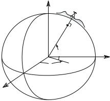
•Lat, Lng, Ht
Geodetic horizontal coordinates are usually expressed as two angles called latitude and longitude (φ, λ). Geodetic vertical coordinates are usually expressed as the distance above the ellipsoid called height.
The angles describe a point’s position on the surface of the reference ellipsoid. The height describes the altitude normal to the surface of
the reference ellipsoid. |
Z |
|
|
e |
e |
|
n |
|
w |
|
i |
|
c |
|
h |
|
M |
|
e |
|
r |
|
i |
|
d |
|
i |
|
a |
|
r
G
h
φ
Y
λ
n
E
quator
X
Fig. 1: Ellipsoidal Geodetic
Coordinates
8
GPS Coordinates
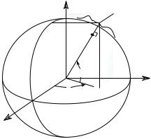
•ECEF XYZ
Geodetic coordinates are some times given in the Earth Centered Earth Fixed (ECEF) Cartesian coordinate system. This coordinate system has its origin at the Earth’s center of mass, the primary (Z) axis is the earth’s spin axis; the secondary (X) axis is the intersection of the equatorial plane and the mean meridian of Greenwich; the tertiary (Y) axis is orthogonal in a right handed system. An ECEF XYZ coordinate can be converted into the corresponding lat, lng, ht using standard formulas.
|
e |
e |
|
n |
|
w |
|
i |
|
c |
|
h |
|
M |
|
e |
|
r |
|
i |
|
d |
|
i |
|
a |
|
n |
|
r
G
Z
yh x
x
z
φ
Y
λ
Equator
X
Fig. 2: Earth Centered Earth
Fixed Geodetic Coordinates
For many surveying applications, the horizontal and vertical coordinate systems are separate. Below are descriptions of common horizontal and vertical coordinate systems used in surveying and mapping.
9

GPS User’s Manual
Horizontal Coordinate Systems
Survey projects use horizontal coordinates on either a local plane or a map projection. For small projects, you can assume a simple flat earth plane and calculate coordinates directly with measured distances. Use TDS localization mode for this procedure. For large projects, a mapping plane is used to accurately represent the curved surface of the earth on a flat plane and conventionally measured distances need to be scaled to the mapping plane grid.
Map Projections
A map projection uses equations to transform local latitude and longitude into (y,x) Cartesian coordinates on a flat plane. Map projections attempt to minimize distortions to the following properties5:
•Conformality
A map projection is conformal when local angles are preserved. Conformal maps are important for surveying because, for second order surveys, angles measured on the ground are angles on the map. Meridians (lines of longitude) and parallels (lines of latitude) intersect at right angles and shape is preserved locally. The physical characteristic of conformality is that the scale factor at any point on the map is the same in all directions.
•Distance
A map projection is equidistant when it correctly plots distances from the center of the projection to any other place on the map. Most map projections involve some distortion of scale. Consequently, when converting distances measured on the ground to distances on the grid, a scale factor must be applied.
•Direction
A map projection is azimuthal when azimuths (angles from a point on a line to another point) are correctly plotted in all directions.
5 http://www.colorado.edu/geography/gcraft/notes/gps/gps_f.html
10
GPS Coordinates
•Area
A map projection is equi-areal when it correctly plots areas over the entire map. That is, all mapped areas have the same proportional relationship to the areas on the Earth that they represent.
Common Conformal Map Projections in Surveying
•Transverse Mercator
The Transverse Mercator (TM) projection results from projecting the ellipsoid onto a cylinder tangent to a central meridian. Scale distortion is maximum from east to west and minimum from north to south, so the TM projection is often used to portray areas with large north-south extent. Distortion of scale, distance, direction and area increase away from the central meridian.
Many national grid systems are based on the TM projection. The Universal Transverse Mercator grid system divides the world into 60 6-degree zones. About half of the U.S. states use a TM projection for their State Plane Coordinate Systems. The British National Grid (BNG) is a TM projection with origin at 49 degrees north latitude and 2 degrees west longitude.
•Oblique Mercator
The Oblique Mercator projection is similar to the Transverse Mercator projection; the ellipsoid is projected onto a cylinder. However, instead of the cylinder tangent to the ellipsoid along a meridian, it is tangent to the ellipsoid along any great circle other than the Equator or a meridian. This makes the Oblique Mercator projection appropriate for regions centered along lines, which are neither meridians nor parallels.
The Oblique Mercator projection is used for Alaska State Plane zone 1, which covers the panhandle.
•Lambert Conformal Conic
The Lambert Conformal Conic projection results from projecting a sphere onto a cone tangent at two (or one) parallels of longitude. Scale distortion is maximum from north to south and minimum from east to west, so the Lambert projection is used to map areas of large east-west extent. Distortion of scale, distance, direction and area increase as you move away from the standard parallels.
11
GPS User’s Manual
Lambert projections are used for about half of the State Plane Coordinate System zones in the USA.
•Stereographic
The Stereographic projection results from projecting an ellipsoid onto a plane. Directions are true from the center point and distortions in scale, area and shape increase uniformly away from the central point. The stereographic projection is azimuthal.
Because the scale is distorted somewhat uniformly in all directions, stereographic map projections are a good representation of a surveyor’s typical flat earth ground coordinate system. For this reason, the stereographic map projection is used by the TDS localization algorithm to convert (lat,lng) into local ground level coordinates. For more information on localization, see page 35.
Scale Factors
When converting distances on a map to distances on the ground, you must correct for two different scale distortions. First, the effects of the map projection distortion must be corrected with the mapping plane scale factor. Second, the geometric effect of your height above the reference surface (ellipsoid height) must be corrected with the ellipsoid scale factor. Generally, these two scale factors are multiplied together into the combined scale factor.
Mapping Plane Scale Factor
This scale factor accounts for the distortions caused by the mapping plane equations as they fit a curved surface onto a flat plane. It is a function of the mapping plane equations and its exact value depends on your location on the map. Although the scale factor is computed with differential equations of the map projection, one can visualize it in a geometric sense. Consider the following diagrams:
12

|
|
|
|
K=1.0 |
|
|
|
K=1.0 |
||||||
|
|
|
|
K>1.0 |
|
|
|
|
K<1.0 |
|
|
|
K>1.0 |
|
|
|
|
|
|
|
|
|
|
|
|
||||
|
|
|
|
|
|
|
|
K=0.9996 |
|
|
|
|
||
|
|
|
|
|
|
|
|
|
|
|
|
|
Distance on Ellipsoid |
|
Mapping Plane |
|
|
|
|
|
|
|
|
|
|||||
|
|
|
|
d |
|
|
|
|
|
|
|
|||
|
|
|
|
i |
|
|
|
|
|
|
|
|||
|
|
|
|
o |
|
|
|
|
|
|
|
|||
|
|
|
|
s |
|
|
|
|
|
Distance on Map |
||||
|
|
|
p |
|
|
|
|
|
||||||
|
|
i |
|
|
|
|
|
|
|
|||||
|
|
l |
|
|
|
|
|
|
|
|
|
|
|
|
|
l |
|
|
|
|
|
|
|
|
|
|
|
|
|
|
E |
|
|
|
|
|
|
|
|
|
|
|
|
|
Central Meridian
Fig. 3: Transverse Mercator Mapping Plane
A side view of the cylinder shows the effect of scale distortion.
GPS Coordinates
•Universal Transverse Mercator Projection
The scale factor at the central meridian (CM) is 0.9996. The scale factor is 1.0 approximately 170-km east and west of the CM. The scale factor is less than one between the CM and the point of tangency. The scale factor is greater than one beyond the point of tangency. Therefore, at the central meridian, a geodetic distance of 100m scales into a mapping plane distance of 99.96m.
Mapping
Plane
h Terrain
Ellipsoid
•TDS Localization Stereographic Projection
The scale factor at the start location (usually the first GPS base station in a project) is calculated for ground distances at the base height. The scale factor increases more or less uniformly in all directions as you move away from the base. The scale factor does not change appreciable within the range of RTK GPS, so this map projection is an excellent way to
model simple flat earth ground level coordinate systems.
13

GPS User’s Manual
Ellipsoid Scale Factor
This scale factor accounts for the height of the ground above the reference surface (the ellipsoid). This scale factor is defined geometrically: Consider the following diagram:
distground/(R+h) = distelip/R
distelip/distground = R/(R+h)
kelip = R/ (R+h)
R = |
a |
|
1 |
||
|
(1− e2 sin2 φ) 2
Combined Scale Factor
Distance on
Ground
Ellipsoid
Height, h
Distance on
Ellipsoid +
R h
Radius of
Ellipsoid, R
Fig. 5: Ellipsoid Scale Factor
Generally, the two scale factors are multiplied together into a combined scale factor. The combined scale factor is then applied to grid distances to get ground distances:
kcf = kelip * kmap
distgrid = distground * kcf
Vertical Coordinate Systems |
|
|
GPS measurements provide ellipsoid heights. Most |
Terrain |
|
survey projects require orthometric elevations. To |
||
|
||
convert heights into elevations, you need to correct |
Geoid |
|
for the difference between the surface of the |
Ellipsoid |
|
reference ellipsoid and the level surface representing |
||
|
||
the gravity field. |
|
The procedure to convert heights (h) to elevations (H) involves the use of a geoid model. The geoid is a theoretical surface that approximates mean sea
level. If one knows the separation between the reference ellipsoid and the geoid, called the geoid undulation (N), then one can determine orthometric elevations from ellipsoidal heights.
h  H
H  N
N
h=H+N
14

GPS Coordinates
Geoid Models in TDS Software
Survey Pro has several geoid models in the coordinate system database. All of the geoid models use data files in geoid grid file (*.GGF) format.
Note: To use a geoid model, geoid data files (*.GGF) must be in the Geodata directory.
•Users in the U.S.A., Mexico, and the Caribbean can use either the NGS Geoid96 or the NGS Geoid99 models. This coverage includes the continental United States, Alaska, Hawaii, Mexico, and the Caribbean.
•Users in Canada can use the Geodetic Survey Division CGG2000 model. See the GSD web site for available data sets.
•Users anywhere in the world can use the NIMA worldwide 15minute geoid height grid data file, WW15mGH.ggf. This file covers the entire globe on a 15’ x 15’ grid.
•Users in Australia can use the AUSGEOID98 data set. This data set is available in several overlapping sub grid files in the *.GGF format at the TDS web site.
Note: To use any of these geoids with Survey Pro, you need to convert the files from their native format into the *.GGF format. This is done with the Geoid Sub Grid function in survey Link. The required NGS and the NIMA geoid model data files are supplied free of charge on the TDS Survey Works CD. The Canadian GSD geoid models are a licensed data set, so you have to contact Natural Resources Canada to obtain the data in the NGS.bin format to use with the Survey Link Geoid Sub Grid extraction utility. The Australian geoid model is available in *.GGF format for download at the TDS web site on the GPS page.6
6 Go to www.tdsway.com and select Downloads.
15
GPS User’s Manual
Survey Pro Coordinate System
Database
Survey Pro uses a Coordinate System Database file (*.CSD) to store the map projection and datum transformation parameters for many different coordinate systems around the world. Also, horizontal and vertical localization adjustments are stored as site records in the database. Below is a list of the terminology used to describe the different records in the coordinate system database.
•Zone: Is the basic record type. A zone record specifies the type of map projection and its parameters. Most zone records have datum and ellipsoid records, and usually a geoid record, already in the database.
•Site: Is a zone record with a horizontal and/or vertical localization adjustment added. Localizations are usually used to correct GPS positions starting from an autonomous base. They can be computed from control points or from manual input of parameters.
•Zone Group: Is a collection of zone and/or site records used to keep the database organized and user selection easier.
•Datum: Is a type of datum transformation and its parameters. A datum record will always have an ellipsoid record already in the database.
•Ellipsoid: Are the two parameters specifying the ellipsoid of the datum.
•Geoid: Is a geoid model and its associated data file.
16
GPS Measurements
This section gives a brief explanation of GPS measurements. First, a discussion of the basic theory of differential positioning will familiarize you with different solution types and their expected precision. Next, step-by-step instructions will describe how to configure Survey Pro with GPS receivers to perform either Real Time Kinematic (RTK) GPS or data collection for post processing differential GPS.
Pseudo-Range Positioning
GPS solutions are computed using pseudo-range positioning: Position is determined from multiple pseudo-range measurements to different satellites (or space vehicles SV) at a single measurement epoch. The position of the GPS receiver antenna is computed by intersecting the pseudo-ranges from the known SV position in a manner similar to survey resection. Four SVs are required to determine three position dimensions and time. Position dimensions are computed by the receiver in Earth-Centered, Earth-Fixed X, Y, Z (ECEF XYZ) coordinates.
A pseudo-range solution will be one of two types: autonomous, or differential. A single GPS receiver can compute an autonomous position from ranges to four or more SV. This single receiver position is extremely coarse. One can expect errors in the order of 100-m on a bad day. For this reason, any precise GPS must be performed using differential positioning.
Differential GPS
Differential GPS (DGPS) positioning involves subtracting a combination of ranges measured to various satellites from multiple receivers. When the signals are subtracted, the major error sources cancel each other out. However, because you are computing a difference in ranges, the DGPS measurement solves for a coordinate difference and not a coordinate. To compute a coordinate using a coordinate difference, you must specify a starting point.
17
GPS User’s Manual
Differential Solutions: Types and Quality
Code Differential
Code differential solutions use the Coarse Acquisition (C/A) navigation code transmitted on the GPS carrier wave. Because the wavelength of the code segment is long (300m), code differential is the least precise differential solution. Accuracies of 1-10 meters are possible with DGPS using C/A code differential positioning.
Carrier Phase Differential
Highly precise coordinate differences can be measured using pseudorange positioning with the carrier signal wave. Because the wavelength of the carrier wave is only 19 cm, mm level positioning is possible. When the signal arrives at the antenna, we can measure the fractional part of the carrier wave. If we can then calculate the whole number of wavelengths between the SV and the antenna (the ambiguity), we can add it to the fractional part and multiply by the length of one cycle to measure a precise range.
Calculating the exact number of wavelengths uses a complicated least squares process, which is often called ambiguity resolution. The ambiguity resolution will yield either a float or a fixed solution.
•Fixed Solution
We know the number of wavelengths will be a whole number. Techniques are used to constrain the least squares solution to yield a whole number. If we get an acceptable solution, we say that this solution is fixed. A fixed solution will generate coordinate differences precise to about 15-ppm (single frequency) or 5-ppm (dual frequency), which translates into 15-mm or 5-mm over a 1-km base line.
Several things may prevent you from achieving a fixed solution: bad multi-path, low number of satellites and bad constellation geometry, poor radio link for corrections (RTK).
•Float Solution
If the constraint algorithm does not produce an acceptable fixed solution, then the ambiguity is allowed to be a decimal (float) number. A float solution will generate coordinate differences precise to about 100 to 500-ppm, which translates into 0.1-m to 0.5-m over a 1-km base line.
18
GPS Measurements
Differential GPS with Survey Pro
DGPS requires raw data measured from separate receivers to be combined into a single range difference. For Real Time Kinematic (RTK) data collection, the raw data can be broadcast using a radio link or cell phones and the differential solution is solved in real time. For Post Processing data collection, the raw data is collected in each receiver’s internal memory and downloaded to a PC. Then, software is used to combine the raw data and produce the differential solution.
Survey Pro supports three different modes of differential GPS data collection: RTK, Post Processing, and Simultaneous RTK and Post Processing data collection.
Selecting Data Collection Mode
1.Go to Settings from the Job menu.
2.On the Receiver card, select RTK or Post Process in the GPS Mode drop down box.
3.Tap 2. .
.
Note: This switch controls the display of the Survey menu when in GPS mode. In RTK mode, the Survey menu contains items to configure a base and rover receiver for RTK data collection. When in RTK mode with post processing turned on, you will get simultaneous post processing data collection every time you occupy a point. In Post Process mode, the survey menu contains items to configure a static or a stop and go receiver for post processing data collection.
19
GPS User’s Manual
RTK Settings
If you are using Survey Pro for RTK, or RTK and post processing simultaneous data collection, the following cards of the Job, Settings screen contain settings specific to RTK:
•Measure Mode: is where you select the receiver dynamic for point occupations and the type of GPS raw data to store for each point. You can also specify measurement acceptance criteria. For more information see the Reference Manual.
•Projection: is where you set your horizontal and vertical projection type and specify the path to geodetic data files. For more information see the Reference Manual.
Post Processing Settings
If you are using Survey Pro for post processing data collection, the following settings apply.
•Post Process: is where you turn on post processing data collection by specifying a recording interval for the receiver’s internal memory. You can also specify how to deal with autonomous positions and select a special layer to store autonomous points on. For more information see the Reference Manual.
20

RTK Data Collection
RTK data collection uses differential GPS corrections broadcast by a base receiver to solve for coordinates at a rover receiver in real time. This section describes how to use Survey Pro for RTK GPS data collection. Topics include:
¾How to select a projection method
¾How to configure the base and rover hardware
¾How to set a base point in the Survey Pro software
¾How to collect control points and solve the horizontal and vertical projections
¾How to collect data and stake out measurements
Setting Projection Mode
When you open a new job in Survey Pro, the Projection Mode is set to Ground - TDS Localization. This is the default mode to produce ground coordinates in any arbitrary coordinate system, such as a resurvey of an old job or a brand new job from a single start point. Using Ground - TDS Localization, the user does not need to select a datum or map projection. Survey Pro will automatically initialize a default projection for ground level distances when you configure the first RTK base station in the job.
If your job requires a specified map projection and datum from the coordinate system database, then you should switch Projection Mode to Mapping Plane. In Mapping Plane mode the user selects a map projection zone from the database or creates a custom zone and datum transformation using Survey Pro.
In either horizontal projection mode, the user can choose one of two methods for vertical projection: Localization (+Geoid), or Ellipsoid Heights. Use Localization (+Geoid) mode when you want the local vertical coordinate to be orthometric elevations. Use Ellipsoid Heights to use the GPS measured height as the local vertical coordinate.
21
GPS User’s Manual
Projection Mode Summary
Horizontal
Ground - TDS Localization
•Local coordinates are at ground level, based on the project height.
•Distances shot with EDM are at ground scale, so are 1:1 with coordinates solved by the projection.
•Default map projection and datum are automatically initialized with RTK base setup.
Mapping Plane
•Local coordinates are on a conformal map projection grid.
•Distances shot with EDM are usually scaled by the combined scale factor to distances on the map projection grid.
•User selects map projection zone.
Vertical
Localization (+Geoid)
•Vertical coordinate is orthometric elevation.
•User must solve transformation from ellipsoid heights to elevations. This is done with Localization on control points, or using a geoid model, or a combination of both.
Ellipsoid Heights
•Vertical coordinate is ellipsoid height.
•This mode requires no transformation setup. Use this mode when vertical coordinates do not need to be elevations.
If you are using GroundTDS Localization for your horizontal projection mode, and you are not using a geoid model, Survey Pro is ready to start the RTK survey upon opening the new job. No projection setup is necessary, so you should move ahead to the next section on Configuring Receivers.
22

RTK Data Collection
Note: If you are using GroundTDS Localization for your horizontal projection mode, and you want to use a geoid, you only need to select the geoid model once. Survey Pro remembers the geoid model you last used and will automatically assign this geoid in a new job's Localization map projection zone. You can go directly to Receiver Setup after opening a job.
If you are using a map projection zone and/or you want to use a geoid, but have never selected one, you will need to choose a zone and/or geoid record from the user interface. The following section describes how to select a map projection and geoid model from the coordinate system database.
1.Go to Projection from the Survey menu. Tap the Settings button at the top of the screen to open the Projection card of the Settings
screen. Select the appropriate Horizontal and Vertical Projection Mode and tap OK .
.
2.If you selected either Mapping Plane or Geoid Model, you can set
them up now. Tap Select Zone… on the Horizontal card and Select Geoid…
 on the Vertical card of the Projection screen. You can also wait and you will be automatically prompted to set them before the first operation that requires these settings.
Note: In Mapping Plane mode, when you select a zone record from the coordinate system database, it may have a geoid model attached. If the selected record has a geoid model attached, this record will become the geoid for the job file and you do not need to tap 6HOHFW *HRLG
*HRLG separately.
23
GPS User’s Manual
Mapping Plane Setup
Use the Mapping Plane Setup screen to either select a map projection zone from one of the zone groups, or select a localized map projection site from the database. This screen is also used to open the Projection Key In Setup wizard where you can key in the parameters of a custom map projection and datum.
1.Tap 6HOHFW =RQH… on the Horizontal card of the Projection screen to open the Mapping Plane Setup screen.
2.To pick a map projection zone from the database, tap View Zones in the Data Base box. To pick a localized map projection site from the database, tap View Sites in the box.
3.If you are picking a map projection zone, select the Zone Group from the drop down list.
4.Select the Zone or Site from the drop down list.
5.If you have selected a zone with a datum and a geoid model attached, the datum and geoid name will be displayed. If you have selected a UTM zone, you must select a Datum from the drop down list.
6.Tap )LQLVK to set the selected zone or site as the current projection record.
Note: When you select a zone with no datum, after you tap )LQLVK , the datum selected in the drop down list will be added to a copy of the selected zone record and you will be prompted to save the new zone record with a unique name.
•Use the 'HOHWH button to delete zones or sites from the database. You can only delete user created sites, you cannot delete the original 'system' records in the database.
Note: You cannot undo the deletion of a zone.
24
RTK Data Collection
•Use the Key In Parameters button to open the Projection Key In Setup screen where you can configure a custom map projection and datum.
Projection Key In Setup
Use the Projection Key In Setup screen to create a custom map projection and a custom datum transformation to use as the selected mapping plane zone:
1.Tap Select Zone… on the Horizontal card of the Projection screen to open the Mapping Plane Setup screen.
2.Tap Key In Parameters > on the Mapping Plane Setup screen to open the Projection Key In Setup screen.
3.Pick the Zone Type for the new map projection zone. Supported zone types are:
•Transverse Mercator
•Lambert 1 parallel
•Lambert 2 parallel
•Stereographic (oblique and polar)
•Oblique Mercator Angle
4.Pick the Datum Type for the new map projection zone. Choices for datum are:
•Pick from Data Base. Select this choice to use a datum from the coordinate system database.
•Custom Molodensky. Select this choice to enter a custom three-parameter datum transformation.
•Custom Similarity. Select this choice to enter a custom seven-parameter datum transformation.
5.Select the Azimuth type for the new map projection zone. Choices are:
•North Azimuth. Select this choice to have a north azimuth grid.
•South Azimuth. This choice to have a south azimuth grid.
6.Select the Grid direction for positive coordinates in the new map projection zone. Choices for grid direction are:
25

GPS User’s Manual
•North\East Grid. Select this choice to have coordinates increase positive in the north and east directions.
•South\West Grid. Select this choice to have coordinates increase positive in the south and west directions.
Note: The geodetic calculation engine and the Survey Pro coordinate geometry engine are separate components. While the geodetic engine can properly handle southwest grid systems, Survey Pro can only operate on a northeast grid system. However, since a southwest grid with a south azimuth is a mirror image of a northeast grid with a north azimuth, Survey Pro can handle this configuration with the following work around: You must set the Azimuth Type to North Azimuth on the Units card of the Job, Settings screen. You then treat north as south and east as west, and the coordinates will be correct for a southwest grid and south azimuth zone.
7.Tap 1H[W to enter the zone parameters for the new map projection.
8.Key in the five or six parameters for your new map projection zone.
9.If your zone is Oblique Mercator Angle, the next screen is used to pick the Origin and Azimuth values.
10.Tap 1H[W to select the datum. The screen that opens will depend on the datum type you specified on the first screen.
11.If you selected Pick from Data Base, pick the database Datum from the list. If you selected either Custom Molodensky or Custom Similarity, then select an ellipse for the new datum. You can select Ellipse from Data Base to use an ellipsoid record from the database, or you can select Key In Ellipse to input parameters for a custom ellipse.
12.Tap 1H[W to open the next screen. If you are using a database datum, the next screen displays the parameters for the new map projection zone and you can 6WRUH
 the record.
13.If you are using a custom datum, enter the datum translations from WGS84 to Local.
26
 Loading...