


User Guide(Ver. 2.1)
Models: N4/8NSL
4/8 Channel Network Video Recorder
About This User’s Guide
Before operating the unit, please read this user’s guide thoroughly and retain it for future reference.
Cautions
Explanation of Graphical Symbols
This symbol indicates the presence of important operating and maintenance (servicing) instructions inthe literature accompanyingthe product.
This symbol indicates the presence of “dangerous voltage” within the product’s enclosure that may be of sufficient magnitude to constitute a risk of electric shock,property damage,personal injury,or death.
WARNING
To reduce a risk of fire or electric shock, do not expose this product to rain or moisture.
CAUTION
Changes or modifications not approved by the manufacture will void the warranty of the product. Using an incompatible battery may increase the risk of fire or explosion.
Replace only with the same or equivalent type battery recommended by the manufacture. Discard used batteries according to manufacturer’s instructions.
2

These precautions must be followed for safety reasons
Warning
Do not use if the unit emits smoke.
Do not disassemble the unit.
Do not place any heavy or sharp objects on the unit.
Do not place on uneven surface.
Do not expose to shock or vibration.
Do not move the unit when the unit is powered on.
Do not block, and allow dust to accumulate in the air vents.
Do not restrict airflow of the unit; doing so can damage the unit.
Only qualified and experienced personnel should perform installation and servicing.
Turn off the power of the NSL when connecting Cameras, Audio Cables.
The manufacturer is not responsible for any damage caused by improper use of the product or failure to follow instructions for the product.
The manufacturer is not responsible for any problems caused by or resulting from the user physically opening the NSL for examination or attempting to repair the unit.
For NSL models with the PoE Switch, it is strongly recommended that the 48V connector is inserted to the PoE Switch before the AC cable is attached to the adaptor.
3
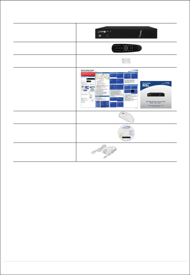
Product Components
Please make sure the following components are included as specified below.
Desktop:
N4NSL / N8NSL
Remote Control
Battery 1.5V (AAA x 2 EA)
Quick Setup Guide &
User Guide
Mouse for NSL |
|
Software & Manual CD |
|
Power Adaptor |
|
(DC48V for POE) |
|
& Power cable (110V or 220V) |
N4NSL : 1.2A, N8NSL : 2A |
4

Specifications for NSL
|
|
MODEL NAME |
|
N4NSL |
|
|
N8NSL |
|
|||
|
|
|
|
|
|
|
|
|
|
|
|
|
|
Description |
|
4ch NVR with 4-PoE |
|
|
8ch NVR with 8-PoE |
||||
|
|
|
|
|
|
|
|
|
|
||
|
|
|
|
IP Camera (Throughput) |
4 |
|
8 |
|
|||
|
|
Input |
|
Normal Resolution |
|
Max. 1920x1080 |
|||||
|
Video |
|
|
Highest Resolution |
|
Not Support |
|||||
|
|
|
|
|
|
|
|
|
|||
|
|
Output |
|
|
Main Monitor |
|
VGA and HDMI (Max. 1920x1080) |
||||
|
|
|
|
|
|
|
|
|
|
|
|
|
|
|
|
Sub Monitor |
|
|
None |
||||
|
|
|
|
|
|
|
|||||
|
|
|
|
|
|
|
|
|
|
||
|
|
Input |
|
IP Camera (Network) |
4 |
|
8 |
|
|||
|
|
|
|
Local Input (RCA) |
|
None |
|
|
None |
||
|
Audio |
|
|
|
|
|
|
||||
|
|
|
|
|
|
|
|
|
|
|
|
|
Output |
|
Local Output (RCA) |
1 |
|
1 |
|
||||
|
|
|
|
|
|||||||
|
|
|
|
|
|
|
|
|
|
||
|
|
|
|
Audio Codec |
|
|
G.711 |
||||
|
|
|
|
|
|
|
|
|
|||
|
|
Sensor |
|
IP Camera (Network) |
4 |
|
8 |
|
|||
|
|
In |
|
|
|
|
|
|
|
|
|
|
Event |
|
Local Input (Terminal Block) |
|
None |
|
|
None |
|||
|
|
|
|
|
|
|
|
|
|
|
|
|
Local Alarm Output (Terminal Block) |
|
None |
|
|
None |
|||||
|
|
|
|
|
|||||||
|
|
|
|
|
|
|
|
||||
|
|
Motion Detection (from IP Camera) |
|
|
Yes |
||||||
|
|
|
|
|
|
|
|
|
|
|
|
|
Serial |
|
|
RS-232C |
|
None |
|
|
None |
||
|
|
|
|
|
|
|
|
|
|
|
|
|
|
|
|
RS-485 |
|
None |
|
|
None |
||
|
|
|
|
|
|
|
|
||||
|
|
|
|
|
|
|
|
|
|||
|
|
Private (IP Camera, Auto Connection) |
|
802.3af x 4 |
|
|
802.3af x 8 |
||||
|
|
|
|
|
|
|
|
|
|||
|
|
LAN (IP Camera, Remote Access) |
|
10/100 Base-TX |
|
|
10/100/1000 Base-TX |
||||
|
Network |
|
|
|
|
|
|
|
|||
|
|
|
Protocols |
|
TCP/IP, UDP, DHCP, HTTP, NTP, SMTP, RTP, RTSP, |
||||||
|
|
|
|
|
|
ONVIF |
|||||
|
|
|
|
|
|
|
|
||||
|
|
|
|
|
|
|
|
||||
|
|
|
|
Streaming |
|
Relay of the IP Camera's Sub-stream |
|||||
|
|
|
|
|
|
|
|
|
|
|
|
|
Live |
|
|
Frame Rate |
|
120fps |
|
|
240fps |
||
|
|
|
|
|
|
|
|
|
|
|
|
|
|
|
|
Frame Rate |
|
120fps |
|
|
240fps |
||
|
|
|
|
|
|
|
|
|
|||
|
Recording |
|
|
Recording Mode |
|
Smart / Continuous / Motion / Sensor / Schedule / Manual |
|||||
|
|
|
|
|
|
|
|
|
|
|
|
|
|
|
Pre Recording |
|
Max. 20 Minutes |
||||||
|
|
|
|
|
|||||||
|
|
|
|
|
|
|
|
||||
|
|
|
|
Post Recording |
|
Max. 60 Seconds |
|||||
|
|
|
|
|
|
|
|
||||
|
|
|
|
|
Search |
|
EZ Search, Date/Time, Event, Archive, Log |
||||
|
|
|
|
|
|
|
|
|
|||
|
Playback |
|
|
Multi-Decoding |
1, 4 |
|
1, 4, 8 |
|
|||
|
|
|
|
|
|
|
|
|
|||
|
|
|
|
Playback Speed |
|
x0.25, x0.5, x2, x4, x8, x16, x32, x64 |
|||||
|
|
|
|
|
|
|
|
||||
|
|
|
|
|
Media |
|
USB drive, External HDD, Network |
||||
|
|
|
|
|
|
|
|
||||
|
Backup |
|
|
File Format |
|
BMP, AVI, Proprietary Format |
|||||
|
|
|
|
|
|
|
|
||||
|
|
|
|
Huge Backup |
|
BMP, AVI, Proprietary Format |
|||||
|
|
|
|
|
|
|
|
|
|
|
|
|
|
|
|
|
Capacity of 1 HDD |
|
3TB |
|
|
3TB |
|
|
Storage |
HDD |
|
Internal HDDs |
1 |
|
1 |
|
|||
|
|
|
|
|
e-SATA |
|
None |
|
|
None |
|
|
|
|
|
|
|
|
|
|
|
|
|
5

|
USB |
Front |
1 |
|
1 |
|
Rear |
1 |
|
1 |
|
|
|
|
|||
|
|
|
|
|
|
User I/F |
Input Method |
|
IR, Mouse |
||
|
|
|
|
||
|
Dynamic DNS |
|
Yes (Free DDNS) |
||
|
|
|
|
||
|
Digital Zoom |
|
Yes |
||
|
|
|
|
||
|
DLS (Day Light Saving) |
|
Yes |
||
|
|
|
|
||
Features |
NTP (Network Time Protocol) |
|
Yes |
||
|
|
|
|
|
|
S.M.A.R.T |
|
Yes |
|||
|
|
||||
|
|
|
|
||
|
Internal Beep |
|
Yes |
||
|
|
|
|
||
|
Multi-Language |
|
Yes |
||
|
|
|
|
||
|
e-mail Notification |
|
Yes |
||
|
|
|
|||
|
3G Mobile |
iPad / iPhone / Android |
|||
|
|
|
|||
Network |
Web Viewer |
Windows (IE, Chrome, Firefox, Safari) |
|||
Access |
|
|
|||
PC Client |
Single / Multi Client and CMS (64 channels) |
||||
|
|
|
|
||
|
Remote Setup and Upgrade |
|
Yes |
||
|
|
|
|
|
|
Power |
Power Supply Voltage |
DC 48V 1.2A |
|
DC 48V 2.0A |
|
|
|
|
|
||
Temperature |
Operation |
41° F ~ 104° F (5°C ~ 40°C) |
|||
|
|
|
|
|
|
|
Storage |
14° F ~ 122° F (-10°C ~ 50°C) |
|||
|
|
||||
|
|
|
|||
Humidity |
Operation |
20% ~ 80% (Non-condensing) |
|||
|
|
|
|||
Dimension |
Unit Dimension (W x H x D) |
11.8' x 8.9' x 2.0' (300mm x 227mm x 53mm) |
|||
|
|
|
|
|
|
Please note that specifications and unit exterior design are subject to change without notification.
6

Table of Contents
1. |
Main Features ............................................................................................................................. |
10 |
2. |
Initial Boot-up Process.................................................................................................................. |
11 |
|
2-1. Initial Boot up and Basic Time Setup..................................................................................... |
11 |
|
2-2. Setting up Daylight Savings Time.......................................................................................... |
12 |
|
2-3. Setting NTP (Network Time Protocol).................................................................................... |
12 |
|
2-4. EZ Setup............................................................................................................................... |
15 |
|
2-5. PoE Port Setup..................................................................................................................... |
17 |
|
2-6 . IP Camera Setup (through Web Viewer page)...................................................................... |
19 |
|
2-7 . Dual Streaming..................................................................................................................... |
19 |
3. |
Front and Rear Panels ................................................................................................................ |
20 |
|
3-1. Desktop Front Panel ............................................................................................................. |
20 |
|
3-2. Connectors ........................................................................................................................... |
20 |
|
3-3. Remote Control..................................................................................................................... |
21 |
4. |
Setup NSL Series........................................................................................................................ |
22 |
|
4-0. Setup – Main Live Screen..................................................................................................... |
22 |
|
4-1. Setup – IP CAMERA............................................................................................................. |
23 |
|
4-1-1. Scan Menu......................................................................................................................... |
25 |
|
4-1-2. ONVIF Setup Menu............................................................................................................ |
26 |
|
4-2. Setup – SYSTEM.................................................................................................................. |
28 |
|
4-3. Setup – RECORD Mode ....................................................................................................... |
34 |
|
4-3-1. Recording Schedules......................................................................................................... |
35 |
|
4-4. Setup – Device Mode............................................................................................................ |
36 |
|
4-4-1. Digital Deterrent................................................................................................................. |
38 |
|
4-4-2. Alarm Box and Keyboard Controller Setup......................................................................... |
39 |
|
4-4-3. Motion Zone Setup............................................................................................................. |
39 |
|
4-5. Setup – DISPLAY Mode........................................................................................................ |
40 |
|
4-6. Setup – NETWORK Mode..................................................................................................... |
41 |
|
4-6-1. Network Types................................................................................................................... |
42 |
|
4-6-2. DDNS ................................................................................................................................ |
42 |
|
4-6-3. Network Port and Web Port................................................................................................ |
43 |
|
4-7. Setup – USER MANAGEMENT Mode................................................................................... |
43 |
|
4-8. Setup – STORAGE Mode ..................................................................................................... |
46 |
|
4-9. Setup - CONFIG Mode.......................................................................................................... |
48 |
|
4-9-1. Firmware Upgrade............................................................................................................. |
49 |
5. Live, Search and Playback.......................................................................................................... |
50 |
|
|
5-1. Live View .............................................................................................................................. |
50 |
|
5-1-1. PTZ Control ....................................................................................................................... |
54 |
|
5-2. Digital Zoom in Live and Playback Screen ............................................................................ |
55 |
|
5-3. SEARCH Screen................................................................................................................... |
55 |
|
|
|
|
7 |
|

5-3-1. EZSearch........................................................................................................................... |
56 |
5-3-2. Smart Search..................................................................................................................... |
57 |
5-3-3. Time Line Search............................................................................................................... |
58 |
5-3-4. Event Search..................................................................................................................... |
58 |
5-3-5. Go To First Time................................................................................................................. |
59 |
5-3-6. Go To Last Time................................................................................................................. |
59 |
5-3-7. Go To Specific Time ........................................................................................................... |
59 |
5-3-8. Archive List ........................................................................................................................ |
59 |
5-3-8. Log List.............................................................................................................................. |
59 |
5-4. Play Mode............................................................................................................................. |
60 |
6. Back Up........................................................................................................................................... |
62 |
6-1. Still Image Backup onto USB Flash Drive.............................................................................. |
62 |
6-2. Video Backup onto USB Flash Drive during playback ........................................................... |
62 |
6-2. EZCopy: Video Backup onto USB Flash Drive during playback............................................. |
64 |
6-3. Transferring Still Images or Video from the ARCHIVE List..................................................... |
64 |
6-4. Playback of Backup Video..................................................................................................... |
65 |
6-5-1. AVI Format......................................................................................................................... |
65 |
6-5-2. NSF Format....................................................................................................................... |
66 |
7. Network Access Using the Multi-Sites Network Viewer .................................................................... |
67 |
7-1. Overview............................................................................................................................... |
67 |
7-2. PC Requirements.................................................................................................................. |
67 |
7-3. Installation of the Program .................................................................................................... |
68 |
7-4. Live Window.......................................................................................................................... |
69 |
7-4-1. Main User Interface............................................................................................................ |
69 |
7-4-2. Control Buttons.................................................................................................................. |
69 |
7-5. Search and Playback Window............................................................................................... |
70 |
7-5-1. Main User Interface............................................................................................................ |
70 |
7-5-2. Main Control Panel ............................................................................................................ |
71 |
7-6. Setup of SpecoTech Multi Client............................................................................................ |
72 |
7-6-1. General.............................................................................................................................. |
72 |
7-6-2. Event ................................................................................................................................. |
73 |
7-6-3. Record............................................................................................................................... |
74 |
7-6-4. Display............................................................................................................................... |
75 |
7-6-5. Language........................................................................................................................... |
76 |
7-6-6. About ................................................................................................................................. |
76 |
7-7. Remote Setup....................................................................................................................... |
77 |
7-7-1. IP Camera.......................................................................................................................... |
78 |
7-7-2. System............................................................................................................................... |
78 |
7-7-3. Record............................................................................................................................... |
81 |
7-7-4. Device................................................................................................................................ |
81 |
7-7-5. Display............................................................................................................................... |
82 |
|
|
8 |
|

7-7-6. Network ............................................................................................................................. |
83 |
7-7-7. User Management ............................................................................................................. |
83 |
7-7-8. Storage.............................................................................................................................. |
85 |
7-7-9. Remote Upgrade................................................................................................................ |
85 |
7-7-10. Information....................................................................................................................... |
85 |
7-8. Operation.............................................................................................................................. |
86 |
7-8-1. Addition, Delete, and Modify of NSL Sites.......................................................................... |
86 |
7-8-2. Connect and Disconnect.................................................................................................... |
87 |
7-8-3. Still-image Capture During Live.......................................................................................... |
88 |
7-8-4. Recording Video on Local PC During Live ......................................................................... |
89 |
7-8-5. Local Playback and Remote Playback............................................................................... |
90 |
7-8-6. AVI Backup during Playback .............................................................................................. |
92 |
8. Network Access Using the Web-Browser Viewer.............................................................................. |
94 |
9. Network Access Using the Smart Phone Viewer.............................................................................. |
96 |
9-1. App Viewer for iPhone........................................................................................................... |
96 |
9-1-1. Live.................................................................................................................................... |
96 |
9-1-2. PTZ Control ....................................................................................................................... |
98 |
9-1-3. Playback............................................................................................................................ |
98 |
9-2. App Viewer for Android Phone............................................................................................... |
99 |
9-2-1. Live.................................................................................................................................... |
99 |
9-2-2. Playback.......................................................................................................................... |
100 |
9-2-3. PTZ Control ..................................................................................................................... |
101 |
APPENDIX: Network Connection - LAN.............................................................................................. |
102 |
APPENDIX: Network Connection – Internet and DDNS...................................................................... |
104 |
9

1.Main Features
Automatic IP Camera Detection and connection (Plug & Play)
Easy Record, Copy and Setup
Easy Search by Thumbnail Preview
Easy Copy
Easy Network
Easy IP Camera Setup
NOTE: Under federal law, The Fourth Amendment to the U.S. Constitution, Title III of the Omnibus Crime
Control and Safe Streets Act of 1968, as amended by the Electronic Communications Privacy Act of 1986 (18
Individual Channel Operation
U.S.C. § 2510, et seq.), and the Foreign Intelligence Surveillance Act of 1978 (50 U.S.C. 1801, et seq.) permit government agents, acting with the consent of a party to a communication, to engage in warrantless interceptions of telephone communications, as well as oral and electronic communications.
Covert camera operation provides enhanced security and administrator control
Dynamically programmable recording priority, motion detection, alarms and scheduling
Simple and Easy Graphic User Interface
Simple Scheduler
HDMI Output
VGA Output
Password to secure installation authorization
Network software supports 10/100Mbps
USB 2.0 port for video clip exporting and easy firmware upgrade via USB Flash Drive
10
2.Initial Boot-up Process
2-1. Initial Boot up and Basic Time Setup
1. During the first boot up, the following logo will be displayed.
2. After the logo, select the language and set date and time as specified below.
1)User has to set a password before using.
Cannot use “1111” when the initial boot up password set.
But user can set ‘1111’ as a password through [Setup > User Management > Password Setup]
2)DVR will not proceed when user put the password “1111”.
(EZ Setup Page Reference, Page 15-16)
11

2-2. Setting up Daylight Savings Time
To enable Daylight Saving feature/NTP synchronization, take the following steps.
1. Enter the Setup mode. The default User ID is “admin”, and enter Password set on initial booting
2. Go to Setup > System > Date & Time Setup
3. Select “on” from the Daylight Saving dropdown menu.
2-3. Setting NTP (Network Time Protocol)
1. Setup > System > NTP Setup > on
12

2. Select the proper Time Zone time.
Table2.3.1. GMT Time Zone
|
|
State |
Standard Time |
Daylight-Saving Time |
|
|
|
|
|
|
|
|
AL |
Alabama |
GMT-6 |
GMT-5 |
|
|
AK |
Alaska |
GMT-9 |
GMT-8 |
|
|
|
|
|
|
|
|
AK |
Alaska (Aleutian Islands) |
GMT-10 |
NA |
|
|
|
|
|
|
|
|
AZ |
Arizona |
GMT-7 |
NA |
|
|
|
|
|
|
|
|
AZ |
Arizona (Navajo) |
GMT-7 |
GMT-6 |
|
|
AR |
Arkansas |
GMT-6 |
GMT-5 |
|
|
|
|
|
|
|
|
CA |
California |
GMT-8 |
GMT-7 |
|
|
|
|
|
|
|
|
CO |
Colorado |
GMT-7 |
GMT-6 |
|
|
|
|
|
|
|
|
CT |
Connecticut |
GMT-5 |
GMT-4 |
|
|
|
|
|
|
|
|
DC |
District of Columbia |
GMT-5 |
GMT-4 |
|
|
DE |
Delaware |
GMT-5 |
GMT-4 |
|
|
|
|
|
|
|
|
FL |
Florida |
GMT-5 |
GMT-4 |
|
|
|
|
|
|
|
|
FL |
Florida (W) |
GMT-6 |
GMT-5 |
|
|
GA |
Georgia |
GMT-5 |
GMT-4 |
|
|
|
|
|
|
|
|
HI |
Hawaii |
GMT-10 |
NA |
|
|
|
|
|
|
|
|
ID |
Idaho (N) |
GMT-8 |
GMT-7 |
|
|
|
|
|
|
|
|
ID |
Idaho (S) |
GMT-7 |
GMT-6 |
|
|
IL |
Illinois |
GMT-6 |
GMT-5 |
|
|
|
|
|
|
|
|
IN |
Indiana |
GMT-5 |
GMT-4 |
|
|
|
|
|
|
|
|
IN |
Indiana (SW / NW) |
GMT-6 |
GMT-5 |
|
|
|
|
|
|
|
|
IA |
Iowa |
GMT-6 |
GMT-5 |
|
|
|
|
|
|
|
|
KS |
Kansas |
GMT-6 |
GMT-5 |
|
|
KS |
Kansas (W) |
GMT-7 |
GMT-6 |
|
|
|
|
|
|
|
|
KY |
Kentucky (E) |
GMT-5 |
GMT-4 |
|
|
|
|
|
|
|
|
KY |
Kentucky (W) |
GMT-6 |
GMT-5 |
|
|
LA |
Louisiana |
GMT-6 |
GMT-5 |
|
|
|
|
|
|
|
|
ME |
Maine |
GMT-5 |
GMT-4 |
|
|
|
|
|
|
|
|
MD |
Maryland |
GMT-5 |
GMT-4 |
|
|
|
|
|
|
|
|
|
|
|
|
|
13

MA |
Massachusetts |
GMT-5 |
GMT-4 |
MI |
Michigan |
GMT-5 |
GMT-4 |
|
|
|
|
MI |
Michigan (W) |
GMT-6 |
GMT-5 |
|
|
|
|
MN |
Minnesota |
GMT-6 |
GMT-5 |
MS |
Mississippi |
GMT-6 |
GMT-5 |
|
|
|
|
MO |
Missouri |
GMT-6 |
GMT-5 |
|
|
|
|
MT |
Montana |
GMT-7 |
GMT-6 |
|
|
|
|
NE |
Nebraska |
GMT-6 |
GMT-5 |
NE |
Nebraska (W) |
GMT-7 |
GMT-6 |
|
|
|
|
NV |
Nevada |
GMT-8 |
GMT-7 |
|
|
|
|
NH |
New Hampshire |
GMT-5 |
GMT-4 |
|
|
|
|
NJ |
New Jersey |
GMT-5 |
GMT-4 |
|
|
|
|
NM |
New Mexico |
GMT-7 |
GMT-6 |
NY |
New York |
GMT-5 |
GMT-4 |
|
|
|
|
NC |
North Carolina |
GMT-5 |
GMT-4 |
|
|
|
|
ND |
North Dakota |
GMT-6 |
GMT-5 |
ND |
North Dakota (W) |
GMT-7 |
GMT-6 |
|
|
|
|
OH |
Ohio |
GMT-5 |
GMT-4 |
|
|
|
|
OK |
Oklahoma |
GMT-6 |
GMT-5 |
|
|
|
|
OR |
Oregon |
GMT-8 |
GMT-7 |
OR |
Oregon (E) |
GMT-7 |
GMT-6 |
|
|
|
|
PA |
Pennsylvania |
GMT-5 |
GMT-4 |
|
|
|
|
RI |
Rhode Island |
GMT-5 |
GMT-4 |
|
|
|
|
SC |
South Carolina |
GMT-5 |
GMT-4 |
|
|
|
|
SD |
South Dakota (E) |
GMT-6 |
GMT-5 |
SD |
South Dakota (W) |
GMT-7 |
GMT-6 |
|
|
|
|
TN |
Tennessee (E) |
GMT-5 |
GMT-4 |
|
|
|
|
TN |
Tennessee (W) |
GMT-6 |
GMT-5 |
TX |
Texas |
GMT-6 |
GMT-5 |
|
|
|
|
TX |
Texas (W) |
GMT-7 |
GMT-6 |
|
|
|
|
UT |
Utah |
GMT-7 |
GMT-6 |
|
|
|
|
VT |
Vermont |
GMT-5 |
GMT-4 |
VA |
Virginia |
GMT-5 |
GMT-4 |
|
|
|
|
WA |
Washington |
GMT-8 |
GMT-7 |
|
|
|
|
WV |
West Virginia |
GMT-5 |
GMT-4 |
|
|
|
|
WI |
Wisconsin |
GMT-6 |
GMT-5 |
|
|
|
|
WY |
Wyoming |
GMT-7 |
GMT-6 |
NOTE: If you want the unit to automatically synchronize the local time, the Time Zone
must be properly set according to your local time zone.
14
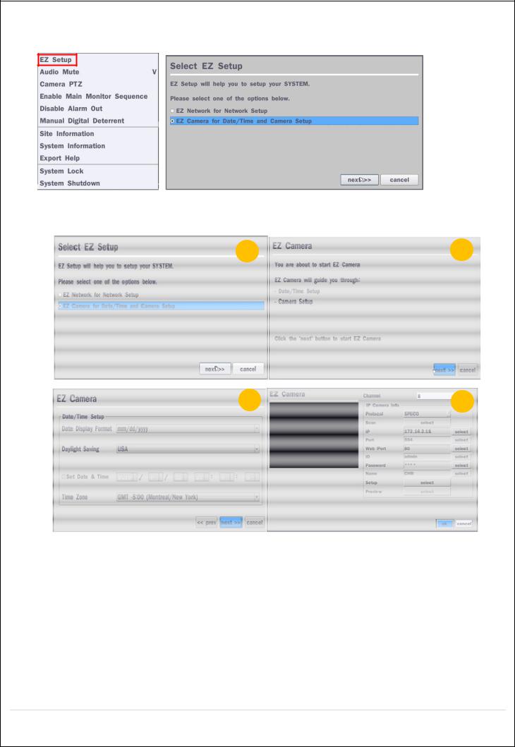
2-4. EZ Setup
Quick installation menu for NS and IP Camera Easy installation(Right-Click on the main screen)
Figure 2.4. EZ Setup Screen 2.4.1. Setup IP Camera configurations
1 |
2 |
3 |
4 |
Figure 2.4.1. EZ CAMERA Setup Procedure
Select EZ Camera for Date/Time and Camera Setup, Click “next” to proceed.
Description of EZ Camera Setup is displayed; Click “next” to proceed.
Set up the Date/Time settings and click “next” to get to the camera setup.
Configure individual cameras in the EZ Camera Setup.
Select the Channel to configure.
Select the Camera Protocol, and then click “select” on Scan menu. (This will scan the network for any IP cameras using the specified protocol.)
Select the desired IP camera from the list, and then click on “register”.
If necessary, click on “Preview” to preview the camera, or Setup to change camera settings.
15
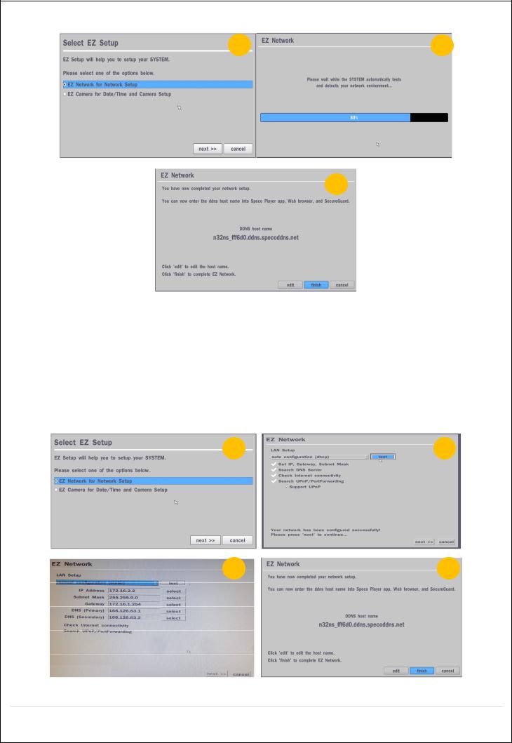
2.4.2. EZ Network (Using an internet connection) |
|
1 |
2 |
3
Figure 2.4.2. EZ Network setup procedure
Select EZ Network for Network Setup.
NVR automatically trying to find an IP address.
Found address and user can edit the address.
Click “finish” to save the setup.
2.4.3.EZ Network setting (Not using internet connection)
1 |
2 |
3 |
4 |
Figure 2.4.3. EZ Network Setup – Manual Configuration Screen
16
Select EZ Network for network setup.
Select Auto Configuration(DHCP) or Manual Configuration(STATIC) and then click “test” button when ready.
Input the Network Settings if Manual Configuration(STATIC) was selected, and click “test”
Click “finish” to save the setup.
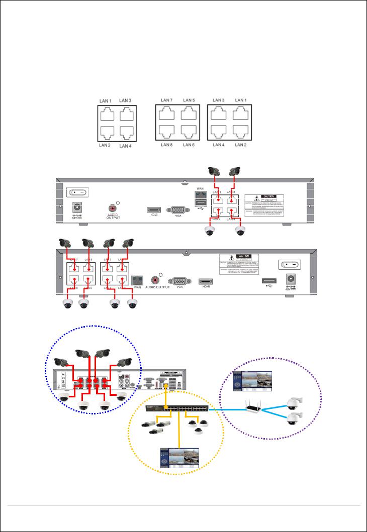
2-5. PoE Port Setup
Figure 2.5.1 PoE Port (N4NSL / N8NSL)
Figure 2.5.1.1 IP Camera Connection Diagram (N4NSL, N8NSL)
Private Network
- IP Cameras
Clients
WAN
Figure 2.5.1.2 IP Camera Connection Diagram (NSL Series)
17
|
|
Table 2.5.1. Factory Default of the IP Camera |
The following IP Camera settings are recommended for optimal connection with the NSL Series |
||
|
|
|
Setup Items |
Default |
Description |
|
|
|
Network Type |
DHCP |
The IP Camera must act as a DHCP client for the “Plug and Play”. |
|
|
|
Encoding Type |
CBR |
The “CBR” is recommended because of the internal buffer design of the NSL |
|
|
Series |
|
|
|
Resolution |
1280x720 |
The maximum performance of the N8NSL is 1080p@240fps or 720p@240fps. |
|
|
To get higher frame rates per channel, 1280x720 is the recommended resolution. |
|
|
|
Frame Rate |
25fps |
The maximum performance of the N8NSL is 720p@240fps. |
|
|
Therefore 30fps per channel is recommended. (30fps x 8 = 240fps) |
|
|
|
Bit Rate |
2Mbps |
The maximum throughput of the N8NSL is 40Mbps. |
|
|
Therefore 2Mbps per channel is recommended. (4Mbps x 8 = 32Mbps) |
|
|
|
Sub Stream |
CIF |
For “Dual Streaming”, the sub stream should be turned on. |
|
512Kbps |
And for the proper streaming through the WAN connection, |
|
|
CIF@512Kbps or lower bitrates per channel is recommended. |
|
|
|
The NSL Series features a "Plug and Play" function with a PoE Switch.
The “Plug and Play” functionality requires the IP Camera to be in DHCP mode.
The NSL automatically assigns an IP Address to the IP Camera. (10.20.30.11 ~ 10.20.30.254)
The NSL models will automatically map the camera on the PoE Port to the corresponding NVR channel number.
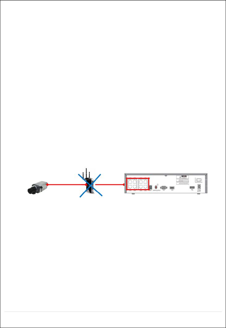
Figure 2.5.1.2. Incorrect connection with the PoE Ports
With the NSL Models, it is prohibited to connect a router to the POE Ports to connect the IP Camera, the NSL will not be able to find and connect to the camera. The LAN Port can be connected to a router, but not the PoE Ports.
18
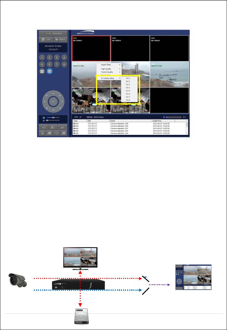
2-6. IP Camera Setup (through Web Viewer page)
NSL Series allow remote access to the IP Cameras through an "IP Camera Setup" menu. The PC Web Client features the "IP Camera Setup" menu that can be accessed remotely.
Click the mouse right button
Select “IP Camera Setup”.
Select Channel Number.
It launches the camera’s web setup page.
In order for the web pages to launch from the “IP Camera Setup” menu when accessed from the WAN, Ports 59011 to 59254 on the router must be port forwarded to the NVR. The local address of the NVR can be found in the system information
2-7. Dual Streaming
High Quality (Main Profile) Video Stream is used for both Recording and Live Display.
High Quality (Main Profile) Video Stream can be viewed through the network, when selected.
Normal (Secondary) Quality Video Stream is used by default when viewing through the network.
Monitoring |
|
|
|
|
|
|
|
High/Normal |
|||
Live Display |
|
|
Selection |
|
|
IP Camera |
|
|
|
Network |
|
|
|
|
|||
|
|
|
|||
|
|
|
|||
Recording |
|
|
|
|
Network Clients |
|
|||||
|
|
|
|
|
|
19 High Quality Video Stream (Full HD)
 Normal Quality Video Stream (D1/CIF)
HDD
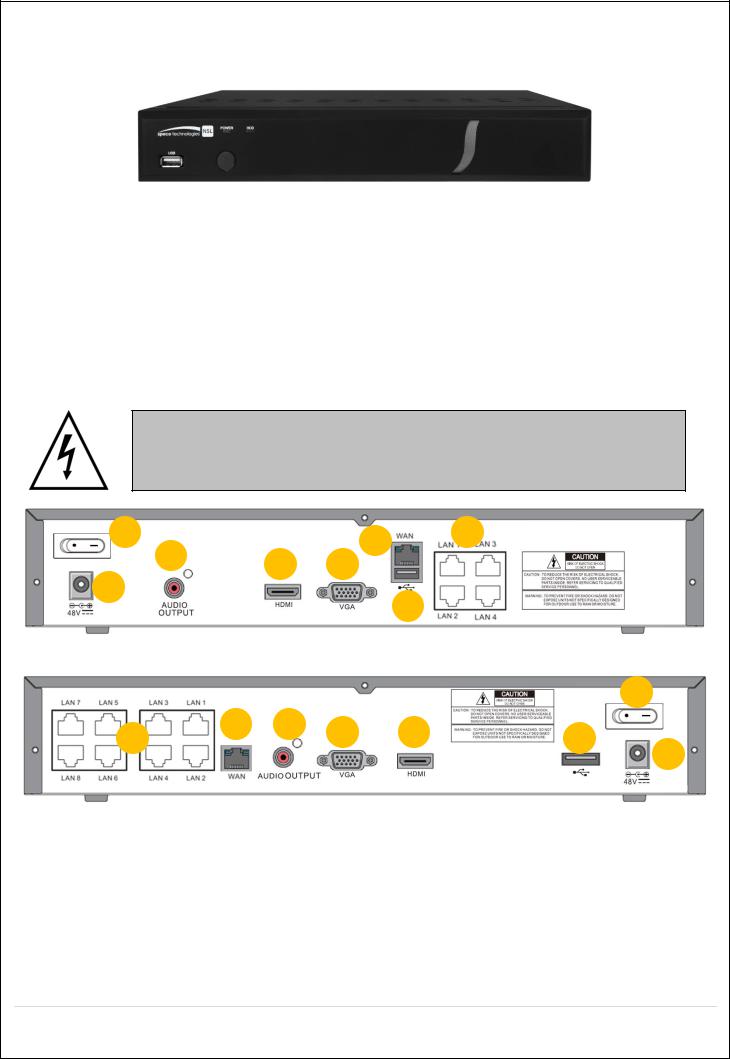
3.Front and Rear Panels
3-1. Desktop Front Panel
|
Figure 3.1.1. Desktop NSL Front panel |
|
Table 3.1.1. Front LED and Port of NSL |
Name |
Description |
POWER |
LED light is on when power is applied to the system. |
HDD |
LED light is on when the system is recording video data. |
USB Port |
This USB port for archiving footage into a USB device. (USB 2.0) |
3-2. Connectors
Do not power this system on before all the connections are completed.
Make sure all the connections are properly secured. Faulty connection may result in the system being damaged.
1 |
4 |
3 |
|
|
5
7 8
2
6
[N4NSL]
1
4 |
5 |
8 |
7 |
|
3 |
|
6 |
||
|
|
|
2
[N8NSL]
Figure 3.2.1. Connectors for NSL
Power Switch: Use for power on/off.
PoE POWER: DC48V input.
PoE PORT: N4NSL (4 Port PoE), N8NSL(8 Port PoE)
WAN PORT: Network Port for Internet
AUDIO OUTPUT: 1 Connector for Audio Output
USB PORT: Connector for USB Mouse or USB flash memory.
20
HDMI OUT: HDMI output port, Connector to the HDMI Monitor, (1280x720, and 1920x1080).
VGA OUT: Connector for VGA Monitor, Main Video Output.
3-3. Remote Control
Figure 2.3.1. Remote Controller Button
ID: To set the remote control ID.
REC: To start and stop manual recording
SEARCH: To go to SEARCH menu.
F/ADV:
During playback – To move the playback position 60 seconds forward .
During Pause – To move the playback position moves 1 frame forward
F/REW:
During playback – To move the playback position 60 seconds back.
During Pause – To move the playback postion 1 frame back.
FF: To fast forward the recording.
PLAY/PAUSE: To play or to pause the recording in playback mode
REW: To rewind the recording.
ESC:
During setup – To retun to the preivous menu screen.
During Playback – To exit playback mode
System lock – To lock a system when pressing ESC button for 5 seconds.
System unlock – To unlock a system when pressing ESC button for 5 seconds.
SETUP: To open the SETUP menu.
Direction buttons: To move menu items or select a channel.
SEQ: To start auto sequencing the screen in full screen mode. (Toggle)
BACKUP: To start a backup operations in live or playback mode
0~9: To select channel (1,2,3,..) or to enter a DVR ID number or use as number key.
21
4.Setup NSL Series
The following sections detail the initial setup of NSL series.
Menu screen will close if user input is not received within 5 minutes.
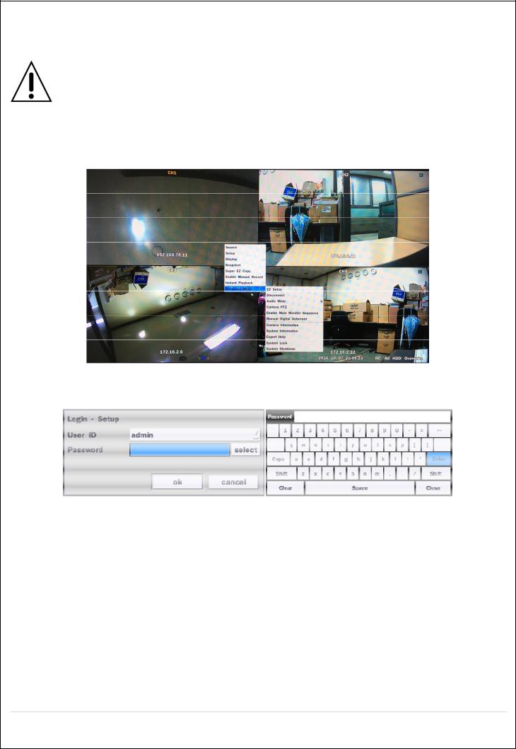
4-0. Setup – Main Live Screen
To enter the setup menu, right click on the mouse and select setup from the submenu or press the setup button on the remote control.
Table 4.0.1. Live Screen and Quick Operation Window
When the NS prompts the Login window, enter the Password using the virtual keyboard, or the front panel, or the remote control. For Admin, user has to enter a password set at initial booting. It is highly recommended to assign a new password to protect the system. User can assign a new password in Security setup menu.
22
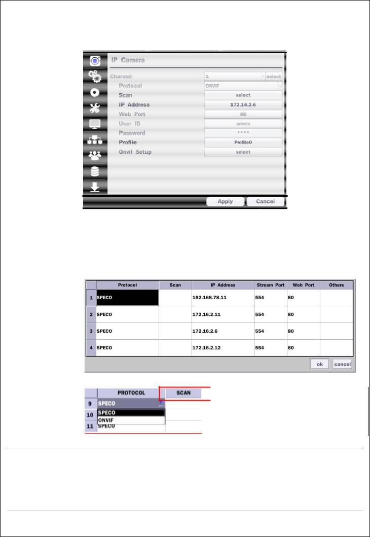
4-1. Setup – IP CAMERA
Press the SETUP button and enter the password. The IP Camera setup menu is displayed below.
|
Figure 4.1.1. IP Camera mode setup screen |
|
Table 4.1.1. Menu items in IP CAMERA mode setup |
Item |
Description |
CHANNEL |
To manually connect each camera, click on the “select” to get this window: |
Under the column labeled Type, Select IP Camera Manufacturer.
 Double Click to Scan
Scan: Double click the empty box to search IP camera on the local network.
23

IP Address: Enter the address of IP camera to connect, or select from scanned list.
Stream Port: Enter the port number of IP camera to connect
Web Port: Enter the web port number of IP camera to connect
Others: Change the IP camera setting. Double click the empty box and then Log-In box will be pop-up. (Enter ID and PASSWORD of IP Camera)
Protocol Select the protocol of the IP Camera
Scan Automatic IP Camera search on the local network.
IP Address Set up IP camera address.
Port Set up the RTSP port of the IP Camera (default: 554)
Web Port Set up the web port of IP Camera (default: 80)
User ID Enter ID of IP camera
Password Enter the Password of IP Camera
ONVIF Setup Set up Video, Network and System of ONVIF IP Camera
24
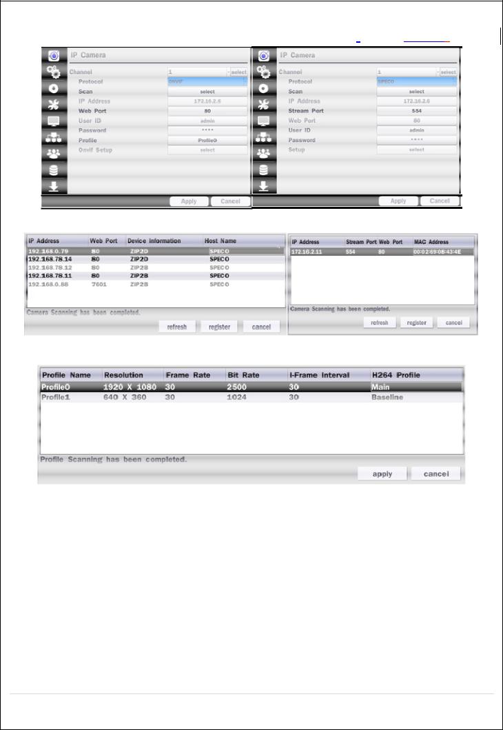
4-1-1. Scan Menu
Scan for IP Cameras on network using SPECO/ONVIF/HIKVISION protocols.protocols
Figure 4.1.2 IP Camera Setup Screen
Figure 4.1.3 Left Image using ONVIF Protocol Scan, Right Image using SPECO Protocol Scan
Figure 4.1.4 ONVIF Protocol Profile SCAN Image
Select the protocol used by the IP Camera and then click the scan button.
Select the IP Camera from the list and then click the register button.
After registering, the basic information is displayed.
IP cameras using ONVIF protocol require ID, Password and Profile to be correctly entered for proper operation.
SPECO protocols only require ID and Password to be correctly entered for proper operation. IP cameras using ONVIF protocol can have their Video, Network and System settings accessed and
updated using the ONVIF setup menu.
(ONVIF Setup Menu may not be accessible depending on the ONVIF version used by the IP camera.)
25
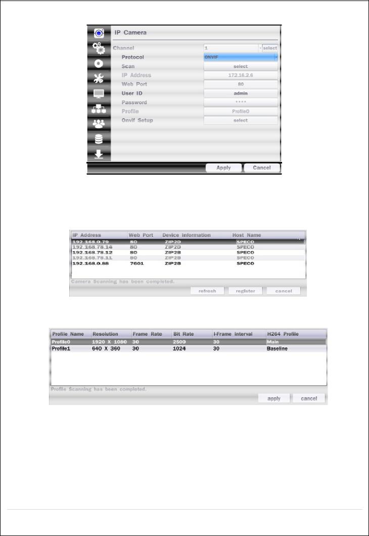
4-1-2. ONVIF Setup Menu
Figure 4.1.2 IP CAMERA Setup Screen (ONVIF)
The NSL Series can search for IP Cameras that are conformant to ONVIF (Open Network Video Interface Forum). In order to search for ONVIF Cameras, the field associated with VENDOR has to be set to ONVIF.
Click on the Box associated with SCAN to scan the networks for ONVIF Conformance cameras.
Figure 4.1.4 ONVIF Camera Scan Window
Figure 4.1.5 ONVIF Profile Scan Window
Select ONVIF for Vendor and click the SCAN button.
Select the camera on the list and then click the register button.
Then, PROFILE and ONVIF setting button will be displayed on the menu.
Click PROFILE button and then the detail information of ONVIF will be searched and listed.
(If there is not on listed, the ONVIF protocol of IP CAM is not compatible with NVR and therefore not supported. )
26
Double click the listed profile to apply.
Enter ID and PASSWORD of IP CAM. Registration is .completed.
Figure 4.1.6 ONVIF Setup Window
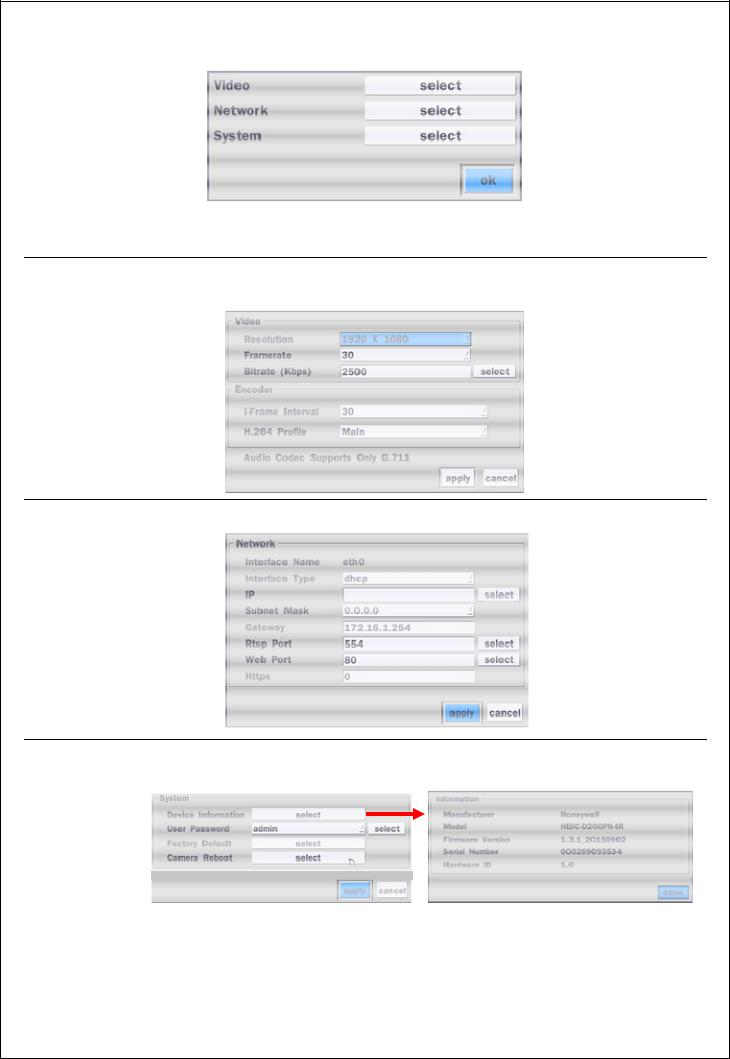
Under ONVIF Setup, the following can be viewed and changed: VIDEO, NETWORK, SYSTEM settings.
Menu Item |
Description |
VIDEO |
Video, Encoder to view and change to audio settings. |
NETWORK View and change Network settings.
|
SYSTEM |
System information and change your password, factory reset and the camera is |
|
|
||||
|
|
rebooting. |
|
|
||||
|
|
|
|
|
|
|
|
|
|
|
|
|
|
|
|
|
|
|
|
|
|
|
|
|
|
|
|
|
|
|
|
|
|
|
|
|
|
|
|
|
|
|
|
|
|
|
|
|
|
|
|
|
|
27
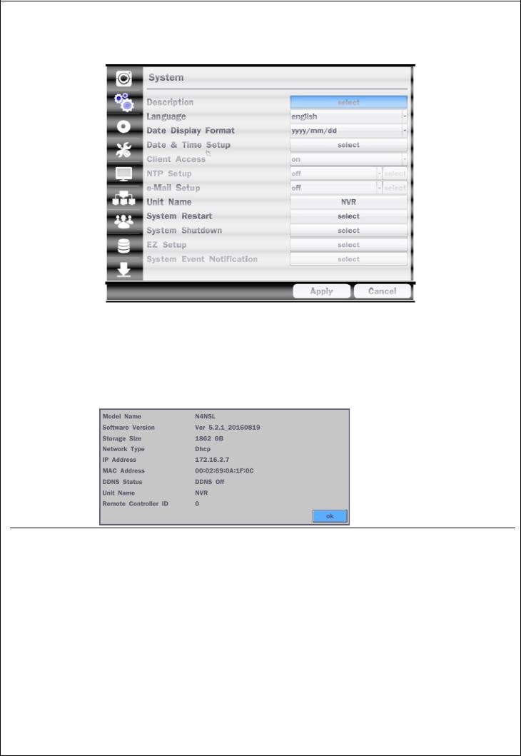
4-2. Setup – SYSTEM
In the SETUP menu, select the SYSTEM tab. Then, the SYSTEM menu is displayed as pictured below. Navigate through the menu items or change the settings using the mouse or the remote control.
|
Figure 4.2.1. SYSTEM Setup Screen |
|
Table 4.2.1. Menu Items in SYSTEM Setup Screen |
Item |
Description |
DESCRIPTION Press the button to view the system information. (Software Version, Storage Size, IP Address, MAC Address and DDNS Status)
LANGUAGE |
Select the display language using the mouse or the remote control. Once a language is |
|
|
selected, the display language will change. |
|
|
|
|
DATE DISPLAY |
Select the date display format using the mouse or the remote control. Options are: |
|
FORMAT |
MM/DD/YYYY, YYYY/MM/DD, DD/MM/YYYY, YYYY-MM-DD, MM-DD-YYYY, DD-MM-YYYY |
|
DATE&TIME |
Select the display date and time using the mouse or the remote control and press OK |
|
SETUP |
button to set the present date and time. |
|
|
Select DAYLIGHT SAVINGS using the mouse or the remote control and select the |
|
|
appropriate daylight savings time zone. The options are: |
|
|
OFF: Daylight saving is turned off. |
|
|
USA: Applies the USA daylight saving time. |
|
|
|
|
|
28 |
|
EU: Applies the EU daylight saving time.
- Select the GMT AREA using the mouse or the remote control.
- Set the time difference with the standard time using the mouse or the button.
|
OTHERS: If the time zone is neither USA nor EU, set the date and time of the daylight |
|
saving period. |
|
- Select BEGIN or END. |
|
Caution |
|
- Do not set the start time to 23:00 for DLS. |
|
- DLS cannot be applied if the date of BEGIN and END is the same. |
|
|
CLIENT |
Enable/Disable remote access through the network. |
ACCESS |
|
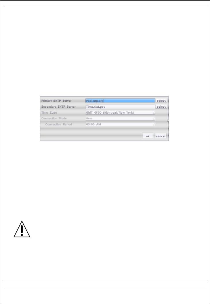
NTP |
NTP (Network Time Protocol) which synchronizes the time of the computer systems over |
SETUP |
variable-latency data networks. |
PRIMARY SNTP SERVER: Input the address of the primary NTP time-server.
SECONDARY SNTP SERVER: Input the address of the secondary NTP time-server.
TIME ZONE: NTP synchronizes with GMT (Greenwich Mean Time) regardless of geography; user must select time difference from GMT.
CONNECTON MODE: Select the NTP time-server connection mode from TIME,
INTERVAL, and ONCE.
CONNECTION PERIOD
-TIME – Refresh the time at the designated time (e.g. 1AM)
-INTERVAL – Every 1 hour ~ 24 hours
-ONCE – Synchronizes time only once. NTP will not synchronize unless the Connection Mode is changed.
NSL sends E-MAIL Notification when the NTP server time is faster than the system
time with below message.
“NTP server time is faster than the system time.
In this case, NTP server time is ignored to protect the user data.
User must set the time manually.
SYSTEM TIME: Mon Oct 10 13:46:49 2011
SERVER TIME: Mon Oct 10 13:33:12 2011
ID: NS
IP ADDRESS: 172.16.2.46
29
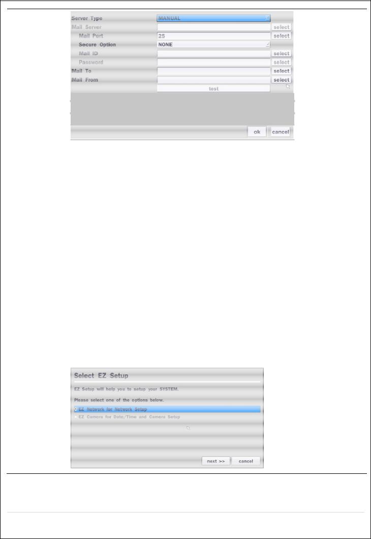
Email Setup
SERVER TYPE: Select GMAIL, HOTMAIL, AOL, YAHOO or MANUAL)
MAIL SERVER: Enter the appropriate mail server information.
MAIL PORT: Assign Mail Port number.
SECURE OPTION: Select the secure mail server connection method. (SSL or TLS) ID: Enter the appropriate mail server ID.
PASSWORD: Enter the appropriate mail server PASSWORD
|
MAIL TO: Enter the appropriate email address to enable sending e-mail reports using a |
|
virtual keyboard. |
|
MAIL FROM: To set the email address sent to the destination host. |
|
TEST : E-mail settings sent a test mail to the registered account |
UNIT NAME |
Name the NSL (e.g. Factory) |
|
This feature is to identify the name of the NSL under the same network. |
|
|
SYSTEM |
Restart the system |
RESTART |
|
SYSTEM |
Shut down the system |
SHUTDOWN |
|
EZ SETUP |
Quick installation Menu for NSL and IP Camera Easy installation |
|
Refer to the detail (2-4. EZ Setup on page 15) |
30
 Loading...