


HTINTB10W
Speco HTINTB10W, HTINTB8W, HT7250IHR, HTINTB9W, HTINTD9 User Manual
...
INSTRUCTION
MANUAL
650Line Intensier3™ Series
Speco Technologies is constantly developing product improvements.
We reserve the right to modify product design and specifications without notice and without incurring any obligation.
Rev. 6/20/2012
HT7246IHR / HT7247IHR / HT7250IHR
(Weatherproof Dome Camera with Chameleon™ Cover)
HTINTB8 / HTINTB9 / HTINTB10
(Weatherproof Bullet Camera with mount plate)
HTINTD8 / HTINTD9 / HTINTD10
(Weatherproof Dome Camera)
HT647HRTP
(Miniature Weatherproof Dome Camera with Chameleon™ Cover)
CVC6245IHR
(Indoor Wall & Ceiling Mount Dome Camera)
CVC6246IHR
(Indoor Wall & Ceiling Mount Dome Camera)
HTINTT5
(Traditional Box type Camera)

Contents
1
◑
Contents ...................................................... 1
◑
Precautions ................................................. 2, 3
◑
Safety Instructions ...................................... 4
◑
Package Contents ....................................... 5
◑
Camera Installation ..................................... 6-13
◑
Specications .............................................. 14-20
◑
Camera Dimension ..................................... 21-23
◑
Features ...................................................... 24-25
◑
OSD Menu Details ...................................... 26- 37
◑
Trouble Shooting ......................................... 38
2
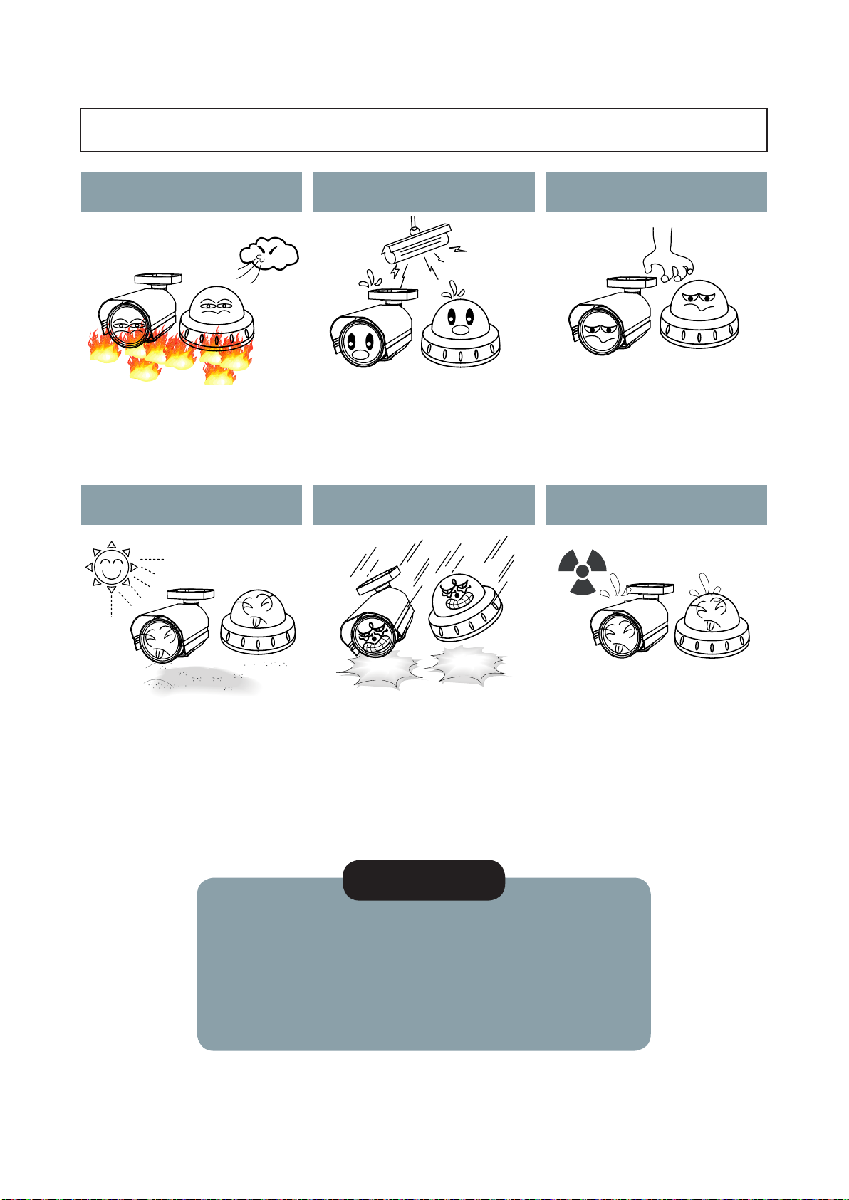
Precautions
Do not install the camera in
extreme temperature conditions.
Do not touch the front lens of the
camera.
Never keep the camera pointed
directly at strong light.
Do not expose the camera to
radioactivity.
Do not install the camera under
unstable lighting conditions.
Do not drop the camera or subject
it to physical shocks.
Only use the camera under conditions
where temperatures are between
-10°C and +50°C. Be especially careful to
provide ventilation when operating under
high temperatures.
This is one of the most important parts of
the camera. Be careful not to leave
fingerprints on the lens cover.
It can cause malfunctions to occur.
If exposed to radioactivity the CCD
will fail.
Severe lighting change or flicker can
cause the camera to work improperly.
Housing damage can compromise
weatherproof ratings.
NOTE
* If the camera is exposed to spotlight or object reflecting strong light,
smear or blooming may occur.
* please check that the power satisfies the normal specification before
connecting the camera.
3
CAUTION
RISK OF ELECTRIC SHOCK
DO NOT OPEN
CAUTION:TO REDUCE THE RISK OF ELECTRIC SHOCK
DO NOT REMOVE COVER(OR BACK).
NO USER-SERVICEABLE PARTS INSIDE.
REFER SERVICING TO QUALIFIED SERVICE PERSONNEL.
ISO14001
CAUTION
RISK OF ELECTRIC SHOCK
DO NOT OPEN
CAUTION:TO REDUCE THE RISK OF ELECTRIC SHOCK
DO NOT REMOVE COVER(OR BACK).
NO USER-SERVICEABLE PARTS INSIDE.
REFER SERVICING TO QUALIFIED SERVICE PERSONNEL.
ISO14001
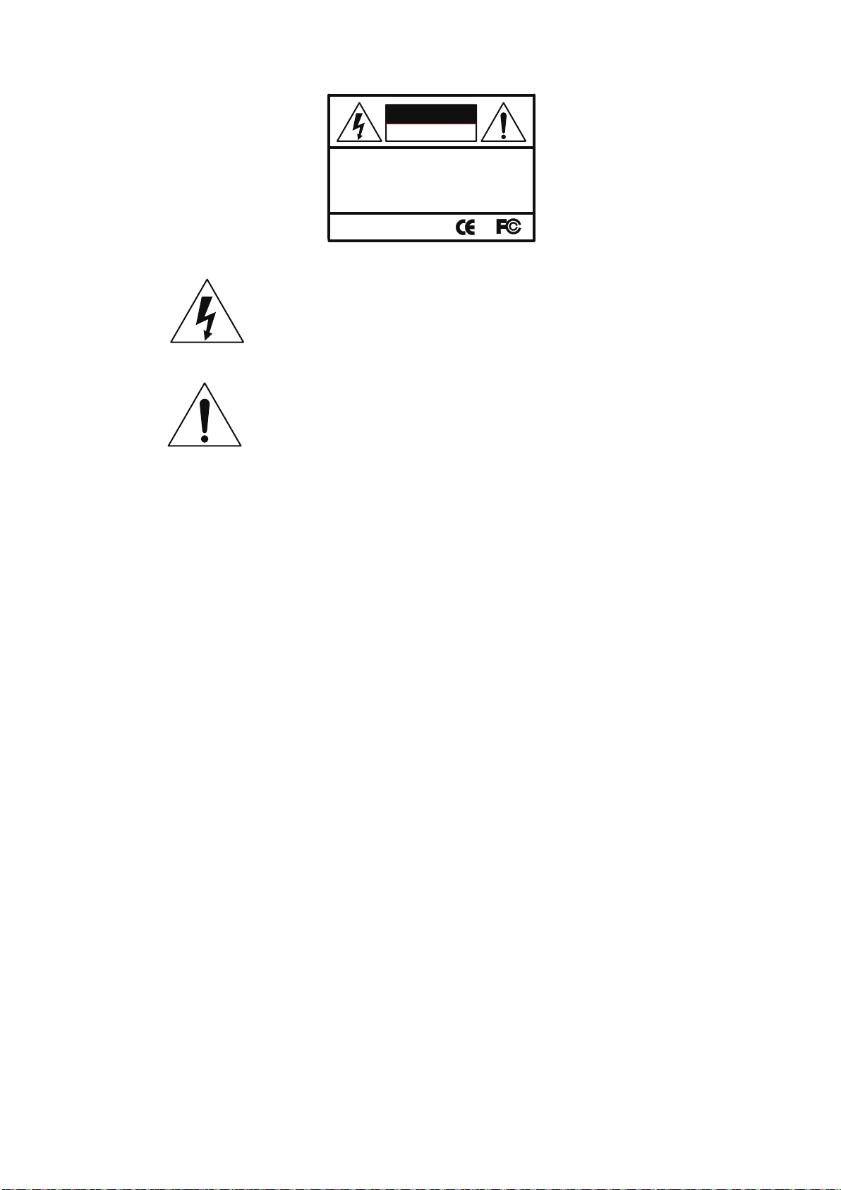
The lightning flash with an arrowhead symbol, within an equilateral
triangle is intended to alert the user to the presence of uninsulated
dangerous voltage within the product's enclosure that may be of
sufficient magnitude to constitute a risk of electric shock to persons.
CAUTION
RISK OF ELECTRIC SHOCK
DO NOT OPEN
CAUTION:TO REDUCE THE RISK OF ELECTRIC SHOCK
DO NOT REMOVE COVER(OR BACK).
NO USER-SERVICEABLE PARTS INSIDE.
REFER SERVICING TO QUALIFIED SERVICE PERSONNEL.
ISO14001
The exclamation point within an equilateral triangle is intended to alert
the user to the presence of important operating and maintenance
(servicing) instructions in the literature accompanying the appliance.
INFORMATION - This equipment has been tested and found to comply with
limits for a Class A digital device, pursuant to part 15 of the FCC Rules & CE Rules.
These limits are designed to provide reasonable protection against harmful
interference when the equipment is operated in a commercial environment.
This equipment generates, uses, and can radiate radio frequency energy and, if
not installed and used in accordance with the instruction manual, may cause
harmful interference to radio communications.
Operation of this equipment in a residential area is likely to cause harmful
interference in which case the user will be required to correct the interference at
their own expense.
WARNING - Changes or modifications not expressly approved by the
manufacturer could void the user’s authority to operate the equipment.
CAUTION : To prevent electric shock and risk of fire hazards:
☞Do NOT use power sources other than those specified.
In USA and Canada, Use Class 2 Power Supply Only

4
Safety Instructions
Precautions for use
Please handle this camera carefully :
◑
This camera should be installed by qualied personnel only
◑
There are no user serviceable parts inside
◑
Do not disassemble this camera other than to make initial adjustments
◑
Use a UL approved regulated 24 volt AC or 12 volt DC power supply
◑
Use appropriate low voltage power cable to prevent re or electrical shock
◑
Please insure that your installation area can support the weight of the camera
◑
Do not use a strong or abrasive detergent when cleaning the camera
◑
Do not install near cooling or heating device

5
Package Contents
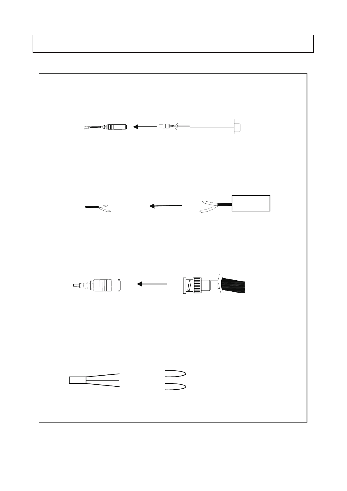
Please make sure that the following items are included in the Package:
1) HT7246IHR, HT7247IHR, HT7250IHR
• 1 Video Test Connector, Power Jack
• 1 Chameleon Cover
• 1 Wrench
• Set Screw
- 3 Tapping Screws 4x40
- 3 Plastic Anchor
2) HTINTB8, HTINTB9, HTINTB10
• 1 Video Test Connector, Power Jack
• 1 Bracket Base
• 2 Wrenches
• Set Screw
- 4 Tapping Screws 4x25
- 4 Hexagon Socket Screws 5x10
3) HTINTD8, HTINTD9, HTINTD10
• 1 Video Test Connector, Power Jack
• 2 Wrenches
• Set Screw
- 3 Tapping Screws 4x25
- 2 Hexagon Socket Screws M6x20
4) HT647HRTP
• 1 Chameleon Cover
• 1 Video Test Connector, Power Jack
• 1 Wrench
• Set Screw
- 3 Tapping Screws 3x40
5) CVC6245IHR, CVC6246IHR
• 1 Video Test Connector, Power Jack
• 2 Screws
- 2 Tapping Screws 4x20
6) HTINTT5
• 1 Foot HD Box Camera
• 1 C-Ring
• 1 Jack HD Box Camera Iris
• 2 Screws
• 1 Power Jack
6
CAMERA INSTALLATION
jvuulj{Gwv~lyGjhislG
XUG~oluG|zpunGXYG}vs{zGkjGOGG\WWGhPG
YUG~oluG|zpunGY[G}vs{zGhjGO[WG}GhP
ZUGjvuulj{G}pklvGjhislG
Tjvuulj{GiujGjhislG{vG{olGiujGqhjrUG
[UGjvuulj{GhGGOyGP
TjGORGSGjvtPGGwGGGOTUGjvtPGG
uGGGlGhGkGGtG
kGG˄vu˅GGGU
kjGXY}GwGz
wGpGaylk
jGaGORP
ishjraOTP
ylkORP
wGz
hjGY[}
R
T
jvtG
hGvG
wGhGkG
uGhGk
7
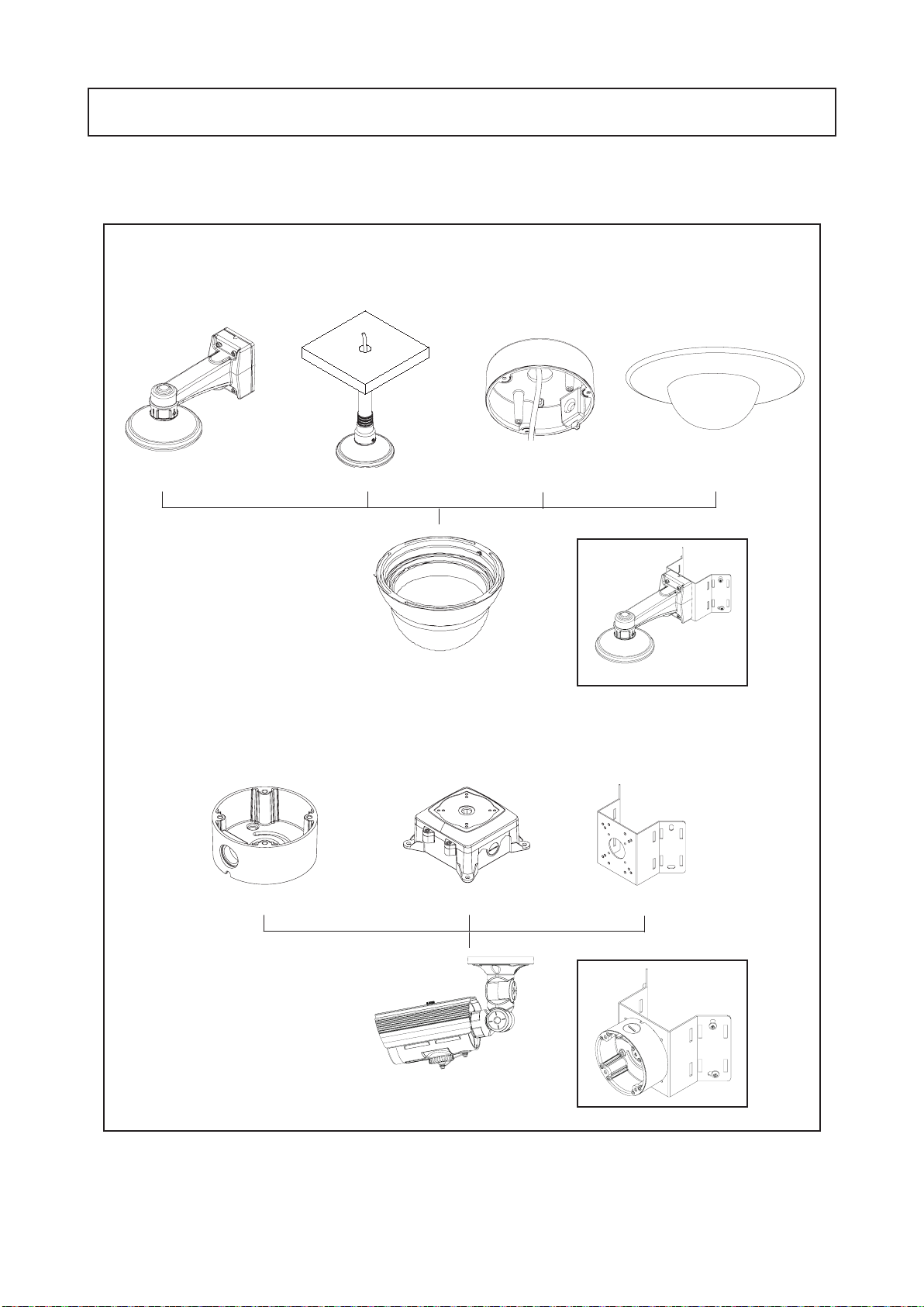
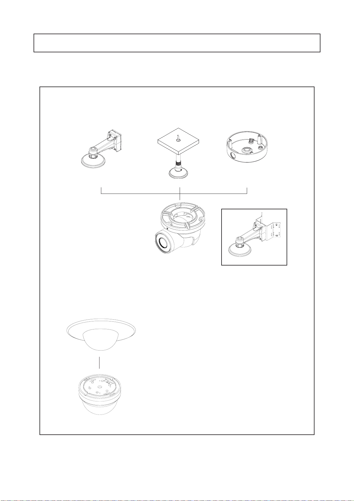
CAMERA INSTALLATION
Compatibility
1) HT7246IHR, HT7247IHR, HT7250IHR
2) HTINTB8, HTINTB9, HTINTB10
INTWM
CVCJBB
INTPM
INTJBS
CVCJBD
INTCM
DFM
8
CAMERA INSTALLATION
Compatibility
3) HTINTD8, HTINTD9, HTINTD10
4) CVC6245IHR, CVC6246IHR
INTWM
DFM
INTPM JB03TG
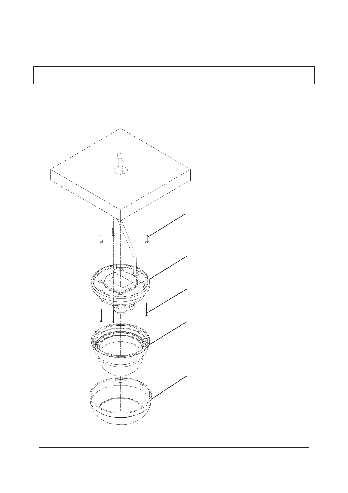
CAMERA INSTALLATION
9
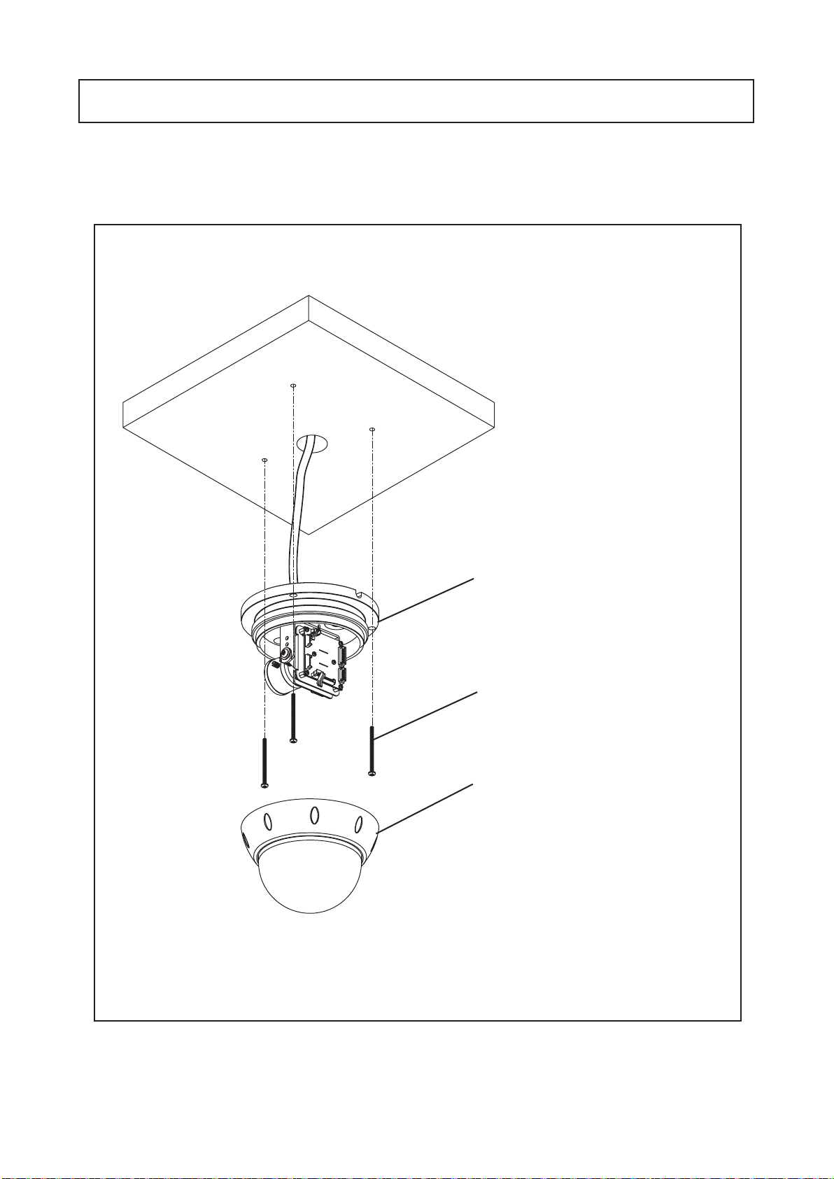
1. HT7246IHR / HT7247IHR / HT7250IHR
CAUTION : The installation instructions in this manual are for use by qualified service
personnel only. To reduce the risk of electric shock, do not perform any servicing other
than that contained in the operating instructions unless you are qualified to do so.
VANDAL DOME BODY ASSEMBLY
BODY OUTER COVER
TAPPING SCREW 4X40, 3EA
VANDAL DOME BASE ASSEMBLY
PLASTIC ANCHOR 6x30, 3EA
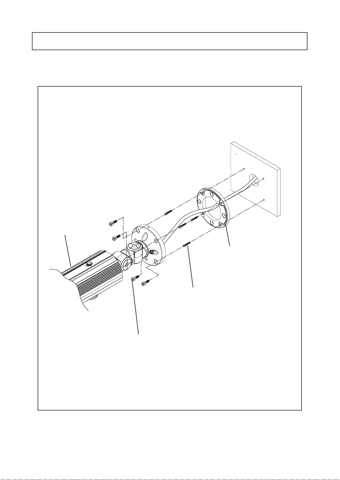
CAMERA INSTALLATION
10
2. HTINTB8, HTINTB9, HTINTB10
CAMERA ASSEMBLY
HEXAGON SOCKET SCREW M5X10, 4EA
TAPPING SCREW 4X25, 4EA
BASE ADAPTOR BRACKET
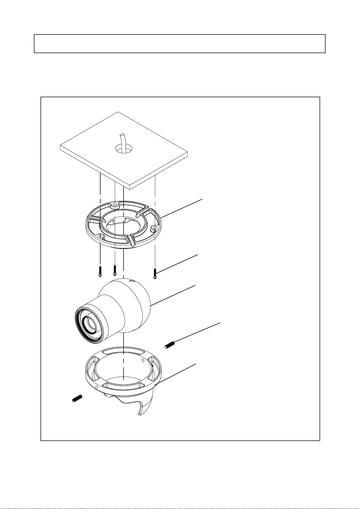
CAMERA INSTALLATION
11
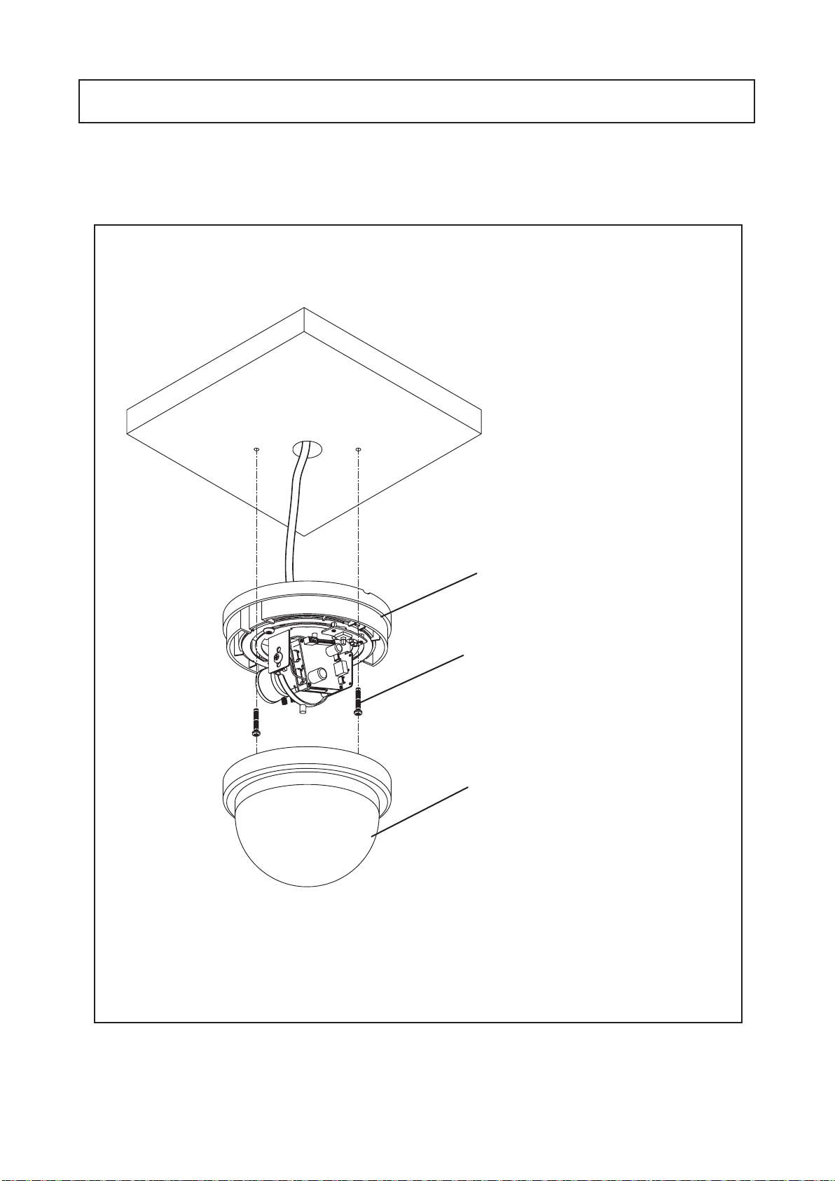
3. HTINTD8, HTINTD9, HTINTD10
DOME BASE
HEXAGON SOCKET SCREW M6X20, 2EA
DOME ASSEMBLY
DOME BODY
TAPPING SCREW 4X25, 3EA
CAMERA INSTALLATION
12
4. HT647HRTP
TAPPING SCREW 3X40, 3EA
BODY & DOME COVER ASSEMBLY
BASE & ROTATE BRACKET ASSEMBLY
CAMERA INSTALLATION
13
5. CVC6245IHR, CVC6246IHR
TAPPING SCREW 4X20, 2EA
DOME COVER ASSEMBLY
BASE ASSEMBLY
 Loading...