


User Manual
4MP IP Camera
O4P4/O4B6/O4B7M/O4D6/O4D7M/O4T7/O4T7M
Please read this instruction carefully before operating the unit and keep it for further reference

Important Safeguards and Warnings
1. Electrical safety
All installation and operation here should conform to local electrical safety codes. Use a certified/listed 12VDC Class2 power supply only.
Please note: Do not connect two power supplying sources to the device at the same time; it may result in device damage! The product must be grounded to reduce the risk of electric shock.
Improper handling and/or installation could run the risk of fire or electrical shock.
2. Environment
Heavy stress, violent vibration or exposure to water is not allowed during transportation, storage and installation. This product should be installed in a cool, dry place away from direct sunlight and heat sources.
Do not install the product in extreme temperature conditions.
Do not expose the camera to electromagnetic radiation. Otherwise it may result in CMOS sensor failure. Do not block any ventilation openings.
Do not allow water and liquid intrusion into the camera.
3. Operation and Daily Maintenance
Please shut down the device and then unplug the power cable before you begin any maintenance work.
Do not touch the CMOS sensor optic component. You can use a blower to clean the dust on the lens surface.
Always use the dry soft cloth to clean the device. If there is too much dust, use a cloth dampened with a small quantity of neutral detergent. Finally use the dry cloth to clean the device.
Please use a professional optical cleaning method to clean the enclosure. Improper enclosure cleaning (such as using cloth) may result in poor IR functionality and/or IR reflection.
The grounding holes of the product are recommended to be grounded to further enhance the reliability of the camera.
Dome cover is an optical device, please don’t touch or wipe cover surface directly during installation and use, please refer to the following methods if dirt is found.
Stained with dirt:
Use oil-free soft brush or hair dryer to remove it gently. Stained with grease or fingerprint
Use oil-free cotton cloth or paper soaked with alcohol or detergent to wipe from the lens center outward. Change the cloth and wipe several times if it is not clean enough.

Warning
This camera should be installed by qualified personnel only.
All the examination and repair work should be done by qualified personnel.
Any unauthorized changes or modifications could void the warranty.
Statement
This guide is for reference only.
Product, manuals and specifications may be modified without prior notice. Speco Technologies reserves the right to modify these without notice and without incurring any obligation.
Speco Technologies is not liable for any loss caused by improper operation.
Regulatory Information
FCC conditions:
This device complies with part 15 of the FCC Rules. Operation is subject to the following two conditions:
This device may not cause harmful interference.
This device must accept any interference received, including interference that may cause undesired operation.
FCC compliance:
This equipment has been tested and found to comply with the limits for a digital device, pursuant to part 15 of the FCC Rules. These limits are designed to provide reasonable protection against harmful interference. This equipment generates uses and can radiate radio frequency energy and, if not installed and used in accordance with the instruction manual, may cause harmful interference to radio communication. However, there is no guarantee that interference will not occur in a particular installation. If this equipment does cause harmful interference to radio or television reception, which can be determined by turning the equipment off and on, the user is encouraged to try to correct the interference by one or more of the following measures:
Reorient or relocate the receiving antenna.
Increase the separation between the equipment and receiver.
Connect the equipment into an outlet on a circuit different from that to which the receiver is connected.
Note:
Before installation, check the package and make sure that all components are included.
Contact your rep or Speco customer service department immediately if something is broken or missing in the package.
Accessory name |
Amount |
|
|
Network Camera Unit |
1 |
|
|
Junction box (Wall mount for O4P4) |
1 |
|
|
Quick Start Guide |
1 |
|
|
Installation Accessories Bag |
1 |
|
|
CD |
1 |
|
|

Table of Contents
1 |
Introduction............................................................................................................................................................................................................. |
|
2 |
|
2 |
Web Access and Login .............................................................................................................................................................................................. |
3 |
||
3 |
Live View.................................................................................................................................................................................................................. |
|
4 |
|
4 |
Camera Configuration .............................................................................................................................................................................................. |
6 |
||
|
4.1 |
System Configuration.............................................................................................................................................................. |
6 |
|
|
|
4.1.1 |
System Information .................................................................................................................................................... |
6 |
|
|
4.1.2 |
Date and Time............................................................................................................................................................. |
6 |
|
|
4.1.3 |
Local Recording........................................................................................................................................................... |
7 |
|
|
4.1.4 |
Storage........................................................................................................................................................................ |
7 |
|
4.2 |
Video Configuration................................................................................................................................................................ |
9 |
|
|
|
4.2.1 |
Image Configuration ................................................................................................................................................... |
9 |
|
|
4.2.2 |
Video / Audio Configuration..................................................................................................................................... |
11 |
|
|
4.2.3 |
OSD Configuration .................................................................................................................................................... |
13 |
|
|
4.2.4 |
Video Mask ............................................................................................................................................................... |
13 |
|
|
4.2.5 |
ROI Configuration ..................................................................................................................................................... |
14 |
|
|
4.2.6 |
Zoom/Focus .............................................................................................................................................................. |
15 |
|
4.3 |
Event Setup........................................................................................................................................................................... |
15 |
|
|
|
4.3.1 |
Motion Detection ..................................................................................................................................................... |
15 |
|
|
4.3.2 |
Other Alarms............................................................................................................................................................. |
16 |
|
|
4.3.3 |
Alarm In (Sensor Input)............................................................................................................................................. |
18 |
|
|
4.3.4 |
Alarm Out ................................................................................................................................................................. |
18 |
|
|
4.3.5 |
Alarm Server ............................................................................................................................................................. |
19 |
|
4.4 |
Analytics Configuration......................................................................................................................................................... |
19 |
|
|
|
4.4.1 |
Abnormality .............................................................................................................................................................. |
19 |
|
|
4.4.2 |
Line Crossing ............................................................................................................................................................. |
20 |
|
|
4.4.3 |
Intrusion.................................................................................................................................................................... |
22 |
|
|
4.4.4 |
Face Detection .......................................................................................................................................................... |
24 |
|
4.5 |
Network Configuration ......................................................................................................................................................... |
27 |
|
|
|
4.5.1 |
TCP/IP........................................................................................................................................................................ |
27 |
|
|
4.5.2 |
Port ........................................................................................................................................................................... |
28 |
|
|
4.5.3 |
Server Configuration................................................................................................................................................. |
28 |
|
|
4.5.4 |
DDNS......................................................................................................................................................................... |
29 |
|
|
4.5.5 |
SNMP ........................................................................................................................................................................ |
29 |
|
|
4.5.6 |
802.1x ....................................................................................................................................................................... |
30 |
|
|
4.5.7 |
RTSP .......................................................................................................................................................................... |
31 |
|
|
4.5.8 |
UPNP......................................................................................................................................................................... |
31 |
|
|
4.5.9 |
Email ......................................................................................................................................................................... |
31 |
|
|
4.5.10 |
FTP ............................................................................................................................................................................ |
32 |
|
|
4.5.11 |
HTTPS........................................................................................................................................................................ |
33 |
|
|
4.5.12 |
QoS............................................................................................................................................................................ |
34 |
|
4.6 |
Security Configuration .......................................................................................................................................................... |
34 |
|
|
|
4.6.1 |
User Admin ............................................................................................................................................................... |
34 |
|
|
4.6.2 |
Online User ............................................................................................................................................................... |
35 |
|
|
4.6.3 |
Block and Allow Lists................................................................................................................................................. |
36 |
|
|
4.6.4 |
Security Management............................................................................................................................................... |
36 |
|
4.7 |
Maintenance Configuration.................................................................................................................................................. |
36 |
|
|
|
4.7.1 |
Backup and Restore .................................................................................................................................................. |
36 |
|
|
4.7.2 |
Reboot ...................................................................................................................................................................... |
37 |

|
|
|
4.7.3 |
Upgrade |
37 |
|
|
|
|||
|
|
|
4.7.4 |
Operation Log ........................................................................................................................................................... |
37 |
5 |
Search.................................................................................................................................................................................................................... |
|
39 |
||
|
5.1 |
|
Image Search ........................................................................................................................................................................ |
39 |
|
|
5.2 |
|
Video Search......................................................................................................................................................................... |
41 |
|
|
|
|
5.2.1 |
Local Video Search.................................................................................................................................................... |
41 |
|
|
|
5.2.2 |
SD Card Video Search................................................................................................................................................ |
42 |
Appendix ........................................................................................................................................................................................................................ |
|
|
45 |
||
Appendix 1 |
Troubleshooting ........................................................................................................................................................................................ |
45 |
|||
Appendix 2 |
Specifications ............................................................................................................................................................................................ |
46 |
|||
1 Introduction
Welcome
Thank you for purchasing this network camera!
Please read this manual carefully before operating the unit and retain it for further reference.
Should you require any technical assistance, please contact Speco Technologies Technical Support at 1-800-645-5516.
Main Features
Built-in PoE (Power over Ethernet)
Integrated IR LEDs for clear vision in low light
IP67 rated for outdoor installations
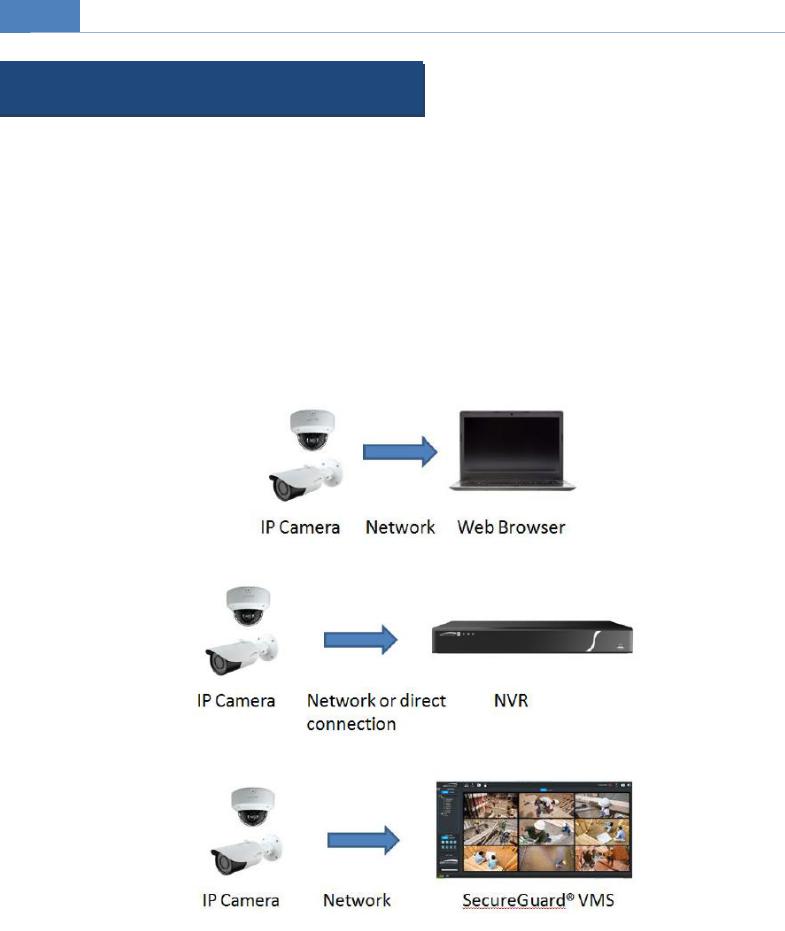
Remote viewing support via web browser, mobile APP, and CMS/VMS
Applications
2
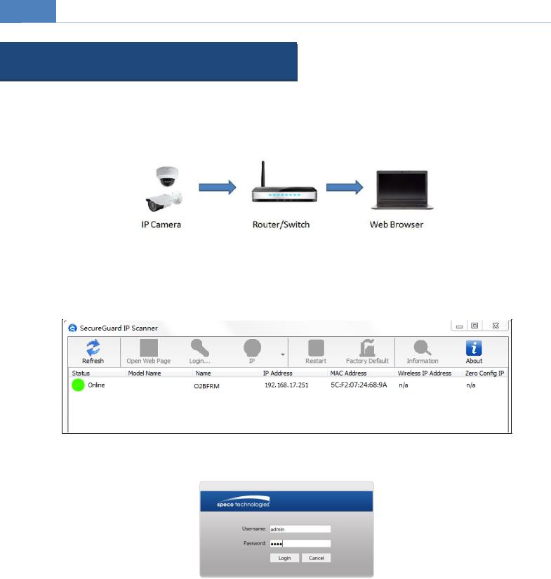
2 Web Access and Login
The IP camera settings can be accessed via a web browser (Internet Explorer 8 and up) through the LAN.
Access through IP Scanner Network connection:
Make sure the PC and IP-Cam are connected on the same local network. The camera is set to DHCP by default and will be assigned an IP address by the DHCP server. Make sure that the local network has a DHCP server. Routers typically have a DHCP server built in.
Install IP Scanner from the CD and run it after installation. IP Scanner is the tool for discovering the IP cameras on the local network.
In the device list, the IP address, model number, and MAC address of each device will be listed. Select the applicable device and double click to open up the web viewer. You can also manually enter the IP address in the address bar of the web browser.
The login interface is shown above. Default user name is admin and password is 1234. After logging in, follow directions to install applicable plug-ins for viewing video.
3
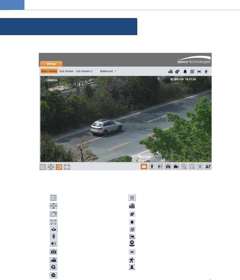
3 Live View
The window below will be shown after logging in.
The following table describes the icons on the live view interface
Icon |
|
|
Description |
Icon |
|
Description |
|
|
|
|
|
|
|
|
|
Original size of resolution |
|
|
Zoom/Focus control (for motorized |
|
|
|
|
|
models) |
||
|
|
|
|
|
|
|
|
|
Fit (correct scale) |
|
|
SD card recording indicator |
|
|
|
|
|
|
|
|
|
|
Auto (fill the window) |
|
|
Abnormal color |
|
|
|
|
|
indicator |
||
|
|
|
|
|
|
|
|
|
Full screen (show video only) |
|
|
Abnormal clarity indicator |
|
|
|
|
|
|
|
|
|
|
Start/stop live view |
|
|
Scene change indicator |
|
|
|
|
|
|
|
|
|
|
Start/stop two-way audio |
|
|
Line crossing indicator |
|
|
|
|
|
|
|
|
|
|
Enable/disable audio |
|
|
Intrusion indicator |
|
|
|
|
|
|
|
|
|
|
Snapshot |
|
|
Sensor alarm indicator |
|
|
|
|
|
|
|
|
|
|
Start/stop local recording |
|
|
Motion alarm indicator |
|
|
|
|
|
|
|
|
|
|
Zoom in (for motorized models) |
|
|
Face detection indicator |
|
|
|
|
|
|
|
|
|
|
Zoom |
out (for motorized |
|
|
|
|
|
models) |
|
|
|
|
All indicator icons above will flash in live view interface only when the corresponding events are enabled.
In full screen mode, to exit, double click on the mouse or press the ESC key on the keyboard.
Click the zoom/focus control button to show the control panel. The descriptions of the control panel are as follows:
4
|
|
|
|
|
|
|
|
|
|
|
|
|
|
|
|
Icon |
|
Description |
Icon |
Description |
|
|
|
|
|
|
|
|
|
|
Zoom - |
|
|
Zoom + |
|
|
|
|
|
|
|
|
|
|
Focus - |
|
|
Focus + |
|
|
|
|
|
|
|
|
|
|
One key focus (used when image is out of focus after manual adjustment) |
|||
|
|
|
|
|
|
|
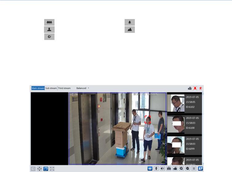
Face Capture View
Go to ConfigEventFace Detection interface. Check “Enable”.
Return to the live view interface. Click  to go to the following interface. When there are faces detected, the face pictures will be listed on the right.
5
4 Camera Configuration
Press the “Setup” button to go to the configuration interface.
Note: Wherever applicable, click the “Save” button to save the settings.
4.1 System Configuration
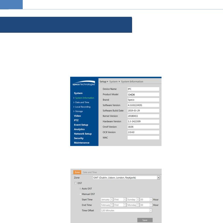
4.1.1 System Information
In the “System Information” interface, the system information of the device is listed.
4.1.2 Date and Time
To set the time and date, go toSystemDate and Time. Please refer to the following interface.
Select the applicable time zone and enable / disable DST as needed.
Click the “Date and Time” tab to set the time and date.
6
4.1.3 Local Recording
Go to SystemLocal Recording to set up the storage path of captured pictures and recorded videos on the local PC. There is also an option to enable or disable the bitrate display in the recorded files.
Additionally, the snapshots triggered by smart events (including face detection, line crossing detection and intrusion detection) can be selected to save to the local PC.
4.1.4 Storage
Go toSystemStorage to go to the interface as shown below.
SD Card Management
When the card is used for the first time, click the “Format” button to format the SD card.All data on the card will be cleared by clicking this button.
Click the “Eject” button to stop writing data to the SD card. Then the SD card can be ejected safely. Snapshot Quota: Set the capacity proportion of captured pictures on the SD card.
Video Quota: Set the capacity proportion of record files on the SD card.
Schedule Recording Settings
1. Go toStorageRecord to go to the interface as shown below.
7
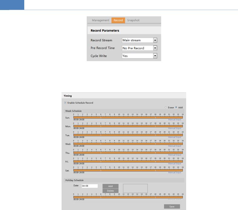
2. Set record stream, pre-record time and cycle writing.
Pre Record Time: Set the time to record before the actual recording begins.
3. Set schedule recording. Check “Enable Schedule Record” and set the schedule.
Weekly schedule
Set the alarm time from Monday to Sunday for a single week. Each day is divided in one hour increments. Green means scheduled. Blank means unscheduled.
“Add”: Add the schedule for a special day. Drag the mouse to set the time on the timeline. “Erase”: Delete the schedule. Drag the mouse to erase the time on the timeline.
Manual Input: Click it for a specific day to enterspecific start and end times. This adds more granularities (minutes).
Day schedule
Set the alarm time for alarm a special day, such as a holiday.
Note: Holiday schedule takes priority overweekly schedule.
Snapshot Settings
Go toSystemStorageSnapshot to go to the interface as shown below.
8

Set the format, resolution and quality of the image saved on the SD card and the snapshot interval and quantity and the timing snapshot here.
Snapshot Quantity: The number you set here is the maximum quantity of snapshots. The actual quantity of snapshots may be less than this number. Supposing the occurrence time of an alarm event is less than the time of capturing pictures, the actual quantity of snapshots is less than the set quantity of snapshots.
Timing Snapshot: Enable timing snapshot first and then set the snapshot interval and schedule. The setup steps of schedule are the same as the schedule recording (See Schedule Recording).
4.2 Video Configuration
Video Configuration includesImage Settings, Video/Audio Setup,OSD, Privacy Mask and Region of Interest.
4.2.1 Image Configuration
In the Image Settings interface as shown below, various settings can be adjusted, such as brightness, contrast, hue and saturation and so on. The common mode and day and night mode can be set up separately. The image effect can be quickly viewed by switching the configuration file.
9
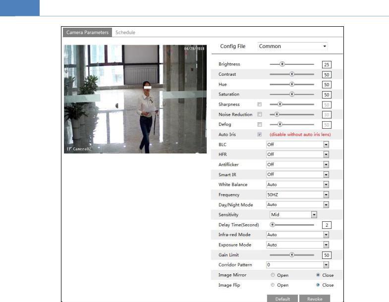
Brightness: Set the brightness level of the camera’s image.
Contrast: Set the color difference between the brightest and darkest parts. Hue: Set the total color degree of the image.
Saturation: Set the degree of color purity. The purer the color, the brighter the image is. Sharpness: Set the resolution level of the image plane and the sharpness level of the image edge. DNR: Digital noise reduction.
Defog: Activatingthis function and setting an appropriate value as needed in foggy, dusty, smoggy or rainy environment to get clear images.
Auto Iris: If your camera is auto Iris, please enable it.
Backlight Compensation (BLC):
Off: disables the backlight compensation function. It is the default mode.
WDR: WDR can adjust the camera to provide a better image when there are both very bright and very dark areas simultaneously in the field of the view by lowering the brightness of the bright area and increasing the brightness of the dark area.
Recording will be stopped for a few seconds while the mode is changing from non-WDR to WDR mode.
HLC: lowers the brightness of the entire image by suppressing the brightness of the image’s bright area and reducing the size of the halo area.
BLC:Ifenabled, the auto exposure will activate according to the scene so that the object of the image in the darkest area will be seen clearly.
HFR: High Frame Rate. If “ON” is selected, the system will restart and then the maximum value of the frame rate of the main stream can be set to 60 fps /50fps.
Antiflicker:
10
Off: disables the anti-flicker function. This is used mostly in outdoor installations.
50Hz: reduces flicker in 50Hz lighting conditions.
60Hz: reduces flicker in 60Hz lighting conditions.
Smart IR: Choose “ON” or “OFF”. This function can effectively avoid image overexposure and underexposure by controlling the brightness of the IR lights according to the actual conditions to make the image more realistic. Please enable it as needed.
White Balance: Adjust the color temperature according to the environment automatically. Frequency: 50Hz and 60Hz can be optional.
Day/Night Mode: Choose “Auto”, “Day”, “Night” or “Timing”. Infra-red Mode: Choose “Auto”, “ON” or “OFF”.
Exposure Mode: Choose “Auto” or “Manual”. If manual is chosen, the digital shutter speed can be adjusted.
Corridor Pattern:Corridor viewing modes can be used for situations such as long hallways. 0, 90, 180 and 270 are available. The default value is 0. The video resolution should be 1080P or below if this function is used.
Image Mirror: Turn the current video image horizontally. Image Flip:Turn the current video image vertically.
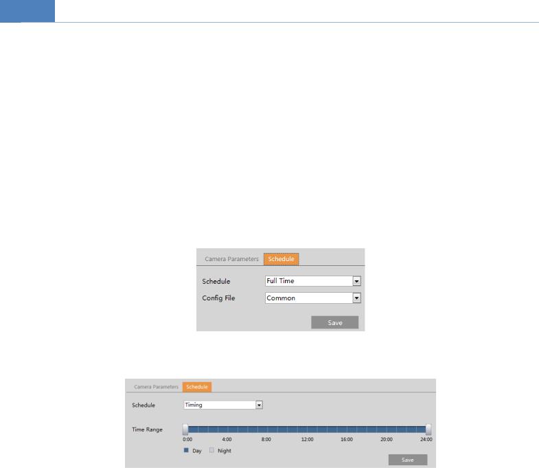
Schedule Settings of Image Parameters:
Click the “Schedule” tab as shown below.
Set full time schedule for common, day or night mode and specified time schedule for day and night. Choose “Timing” in the drop-down box of schedule as shown below.
Drag “  ” icons to set the time of day and night. Blue means day time and blank means night time. If the current mode of camera parameters is set to “Timing”, the image configuration mode will automatically switch between day and night according to the schedule.
4.2.2 Video / Audio Configuration
Go toImageVideo / Audiointerface as shown below. In this interface, set the resolution, frame rate, bitrate type, video quality and so on subject to the actual network condition.
11
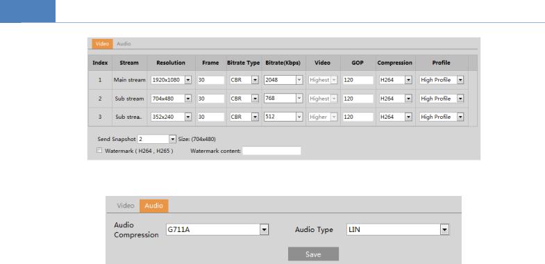
Click the “Audio” tab to go to the interface as shown below.
Three video streams can be adjustable. Resolution: The size of image.
Frame rate: The higher the frame rate, the video is smoother.
Bitrate type: CBR and VBR are optional. Bitrate is related to image quality. CBR means that no matter how much change is seen in the video scene, the compression bitrate will be kept constant. VBR means that the compression bitrate will be adjusted according to scene changes. For example, for scenes that do not have much movement, the bitrate will be kept at a lower value. This can help optimize the network bandwidth usage.
Bitrate: it can be adjusted when the mode is set to CBR. The higher the bitrate, the better the image quality will be.
Video Quality: It can be adjusted when the mode is set to VBR. The higher the image quality, the more bitrate will be required.
I Frame interval: It determines how many frames are allowed between a “group of pictures”. When a new scene begins in a video, until that scene ends, the entire group of frames (or pictures) can be considered as a group of pictures. If there is not much movement in the scene, setting the value higher than the frame rate is fine, potentially resulting in less bandwidth usage. However, if the value is set too high, and there is a high frequency of movement in the video, there is a risk of frame skipping.
Video Compression:MJPEG, H264+, H264, H265+ or H265 can be optional. If H.265/H.265+ is chosen, make sure the client system is able to decode H.265/H.265+.
Profile: For H.264. Baseline, main and high profiles are selectable. Send Snapshot: How many snapshots to generate for an event.
Video encode slice split: If this function is enabled, smooth image can be gotten even though using the low-performance PC. Watermark: When playing back the local recorded video in the search interface, the watermark can be displayed. To enable it, check the watermark box and enter the watermark text.
Audio Encoding: G711A and G711U are selectable. Audio Type: LIN. Some models may support MIC type.
12
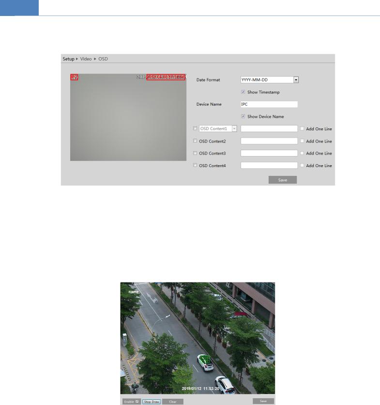
4.2.3 OSD Configuration
Go toVideoOSDinterface as shown below.
Set time stamp, device name, OSD content and picture overlap here. After enabling the corresponding display and entering the content, drag them to change their position. Then click the “Save” button to save the settings.
Picture Overlap Settings:
Check “OSD Content1”, choose “Picture Overlay” and click “Browse” to select the overlap picture. Then click “Upload” to upload the overlap picture. The pixel of the image shall not exceed 200*200, or it cannot be uploaded.
4.2.4 Video Mask
Go to ImageVideo Maskinterface as shown below.A maximum of 4 zones can be set up.
To set up video mask:
1.Enable video mask.
2.Click the “Draw Area” button and then drag the mouse to draw the video mask area.
3.Click the “Save” button to save the settings.
4.Return to the live to verify that the area have been drawn as shown as blocked out in the image.
13

To clear the video mask:
Click the “Clear” button to delete the current video mask area.
4.2.5 ROI Configuration
Go to ImageROI Config interface as shown below. An area in the image can be set as a region of interest. This area will have a higher bitrate than the rest of the image, resulting in better image quality for the identified area.
1.Check “Enable” and then click the “Draw Area” button.
2.Drag the mouse to set the ROI area.
3.Set the level.
4.Click the “Save” button to save the settings.
14
 Loading...