


HTSD37XH

HTSD37XH
(37X Optical Zoom)
HTSD28XH
(28X Optical Zoom)
960H Indoor / Outdoor Speed Dome Cameras
Please read this manual thoroughly before operation and keep it handy for further reference
2/56
CAUTION
RISK OF ELECTRIC SHOC
K
DO NOT OPEN
CAUTION : TO REDUCE THE RISK OF ELECTRICAL SHOCK, DO NOT OPEN THE COVERS.
NO USER SERVICEABLE PARTS INSIDE.
REFER SERVICING TO QUALIFIED SERVICE PERSONAL
This lightning flash with arrowhead symbol is intended to alert the
user to the presence of un-insulated "dangerous voltage" within the
product's enclosure that may be of sufficient magnitude to
constitute a risk of electric shock to persons.
This exclamation point symbol is intended to alert the user to the
presence of important operating and maintenance (servicing)
instructions in the literature accompanying the appliance.
This Device compiles with Part 15 of the FCC Rules. Operation is
subject to the following two conditions:
(1) This device may not cause harmful interface, and
(2) This device must accept any interference received, including
interference that may cause undesired operations.

3/56
Important Safety Guide
1. Read, heed and follow all the instructions
Read all the safety and operating instructions before using the product.
2. Keep this manual
Keep this manual for reference in future.
3. Attachments / Accessories
Use only the attachments or accessories specified by the manufacturer.
4. Installation
Do not install near any heat resources such as radiators, heat registers, stoves,
or other appratus including amplifiers that product heat. Improperly installed
product may fall, cause serious injury to a child or adult and damage the
product.
Do not block any ventilation holes or openings. Install in accordance with the
manufacturer’s instructions.
Use only with the cart, stand, tripod, bracket, mounting devices, or table
specified by the manufacturer.
Installation should be done only by qualified personnel and conform to all the
instructions by the manufacturer.
Refer all servicing to qualified service personnel.
Unless the product is specifically marked as IP67, more than IP67 or confirmed
by the manufacturer, it is designed for indoor use only and it must not be
installed where exposed to rain and moisture.
Do not load on the product.
Use stainless steel hardware to fasten the mount.
To prevent damage from water leakage when installing a mount outdoors on a
roof or wall, apply sealant properly around holes.
These servicing instructions are for use by qualified service personnel only.
To reduce the risk of electric shock, do not perform any servicing other that
contained in the operationg instructions unless you are qualified to do so.
Use only replacement parts specified by the manufacturer.
5. Power source
This product should be operated only from the type of the power source indicated
on the marking label.
NOTICE

4/56
Caution
Operating
Before using, make sure that the power supply and others are properly
installed.
While operating, if any abnormal condition or malfunction is observed, stop
using the product immediately and then contact your local dealer.
Handling
Do not disassemble or tamper with the parts inside the product.
Do not drop or subject the product to shock and vibration as this can damage
the product.
Care must be taken when you clean the clear dome cover. Especially, scratch
and dust will ruin the quality of the product.
Installation and Storage
Do not install the product in areas of extreme temperature, which exceed the
allowable range.
Avoid installing in humid or dusty places.
Avoid installing in places where radiation is present.
Avoid installing in places where there are strong magnetic fields and electric
signals.
Avoid installing in places where the product would be subject to strong
vibrations.
NOTICE
5/56
①
①①
① Introduction
Feature
s
__________________
6
Package Components
9
Main Part Description
1
0
②
②②
② Installation
DIP Switch Setup
1
1
Installation with
Ceiling Mount Bracket
1
4
Installation with Wall Mount Bracket
1
5
Wiring
and Cabling
1
6
③
③③
③ Operation
Check Point before Operation
19
Check Points for Preset and Pattern Function before Operation
19
OSD
Menu
2
0
Reserved Preset (Hot Keys)
2
0
Preset
2
1
Swing
2
1
Pattern
2
2
Group
2
3
Other Functions
2
3
OSD Display
2
5
④
④④
④ OSD Menu
Quick P
rogramming Guide
2
6
Main Menu
2
6
Display
Setup
2
7
Privacy Zone Mask Setup
2
8
Clock Setup
30
Camera Setup
3
1
Motion Setup
3
5
Preset Setup
3
8
Swing Setup
4
0
Pattern Setup
4
1
Group Set
up
4
2
Schedule Setup
4
5
Password Setup
4
6
S
ystem Initialize
4
8
⑤
⑤⑤
⑤ Specifications
49
Dimens
ion
s
5
3
TABLE OF CONTENTS

6/56
Features
Powerful Zoom Camera & Setup Options
Image Sensor : 1/4" Interline Transfer CCD
Zoom : HTSD37XH (×37 Optical Zoom, ×32 Digital Zoom)
: HTSD28XH (
×28 Optical Zoom, ×32 Digital Zoom)
Day & Night, Privacy Mask and WDR
DNR (Digital Noise Reduction) Function
Various Focus Mode : Auto-Focus, Manual Focus, Semi-Auto Focus
Various Setup Options in OSD Menu.
Powerful Pan/Tilt Functions
MAX. 500°/sec High Speed Pan/Tilt Motion
With the Vector Drive Technology, Pan/Tilt motions are accomplished along
the shortest path. As a result, the time to target view is remarkably short and
the video on the monitor is very natural in monitoring.
With the Micro-Stepping Control Technology, the video looks very natural at
high zoom magnification during a jog operation on a controller since the
camera can be controlled by 0.05°/sec. Hence it is very easy to make the
camera focus on desired target views at high zoom magnification.
Additionally it is easy to make the camera focus on desired positions with
zoom-proportional pan/tilt movement.
RTC(Real Time Clock) Function
Date and Time can be configured for Schedule Function
With Backup Battery Function, Date and Time configuration should be kept up for a
while, even though power is off
I
NTRODUCTION
1
7/56
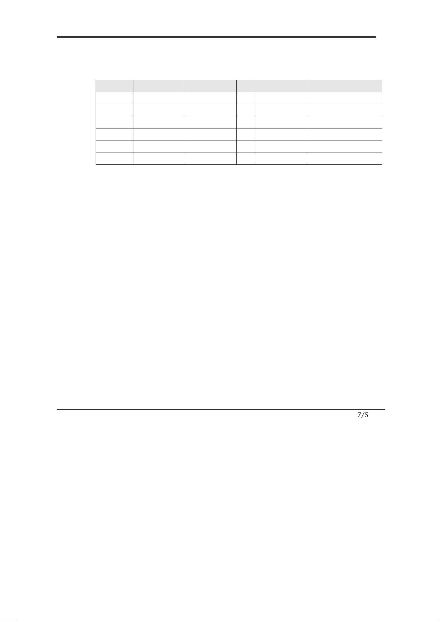
Preset, Pattern, Swing, Group, Schedule, Privacy Mask and More…
MAX. 209 Presets are programmable and each preset can have its own
parameter values independently from the other presets.
For an example, refer to the below table.
Preset N
o.
White Balance
Auto Exposure
•••
Label
Remarks
Preset 1
C
ase
A
Case
3
“
E
NTRANCE
”
Preset 2
C
ase
C
Case
5
“
WAREHOUSE
”
•••
Preset 95
−
−
−
−
Reserved for
OSD
Menu
•••
Preset 255
C
ase
K
Case
9
“
TERRACE
”
MAX. 10 sets of Swing are programmable. This function is that a camera
moves repetitively between two preset positions at programmed speeds.
MAX. 8 Patterns are programmable. This function is that a camera memorizes
the path (mostly curve path) by the joystick of the controller and revives the
trajectory operated by the joystick as closely as possible.
MAX. 8 sets of Group are programmable. This function is that a camera
memorizes the combination of Presets, Pattern and/or Swings sequently and
runs Presets, Pattern and/or Swings repetitively. A Group can be combined
upto 40 functions with any of Preset/Pattern/Swing.
MAX. 8 Privacy Masks are programmable, not to intrude on any other’s
privacy.
MAX. 8 sets of Schedule are programmable. This function is that a camera runs a
function such as Preset, Pattern, Swing or Group at an assigned time. Also this
function can be run periodically by pre-defined schedules.
PTZ(Pan/Tilt/Zoom) Control
With the RS-485 communication connection, MAX. 255 units of cameras can
be connected to a single controller.
Pelco-D or Pelco-P protocols can be selected as a control protocol in the
current firmware version.
OSD(On Screen Display) Menu
OSD menu is provided to display the status of camera and to configure the
functions interactively. A P
assword can be configured in OSD menu and OSD
menu can be protected.
The information such as Camera ID, Pan/Tilt Angle, Time/Date, Direction,
Alarm Input and Preset is displayed on screen.
Multi-Language OSD menu is supported.
I
NTRODUCTION
1

8/56
Alarm In/Out Function
3 alarm sensor inputs and 1 alarm sensor outputs are available.
Alarm sensor input is decoupled with photo-couplers to avoid external
electric noise and shock perfectly.
Both of N.O.(Normal Open) sensors and N.C.(Normal Close) sensors can be
used and the signal range of the sensor input is from DC 5.0V to 12.0V for
various applications.
The camera can be set to move to a Preset position or to run functions such
as Pattern, Swing and Group when there are external sensor activations. Also
“Post Alarm” function is possible, which is supposed to activate after user-
defined time period and sequentially in succession to the action by external
sensor activations.
Reserved Presets(Hot Keys)
Most camera setup options can be set up easily and directly with the
reserved presets (Hot Keys), without entering into OSD menu. For more
information, refer to “Reserved Presets(Hot Keys)” in this manual.
Dual Power Input
The input power source is DC 12 V or AC 24 V.
Perfect Outdoor Environment Compatibility and Easy Installation
The fans and heaters are built-in in the camera for cold and hot temperature
environment. Also idealistic mechanical design protects the camera from
water and dust. (IP67 when installed properly with wall mount bracket only)
It is easy to install and repair the camera.
I
NTRODUCTION
1
9/56
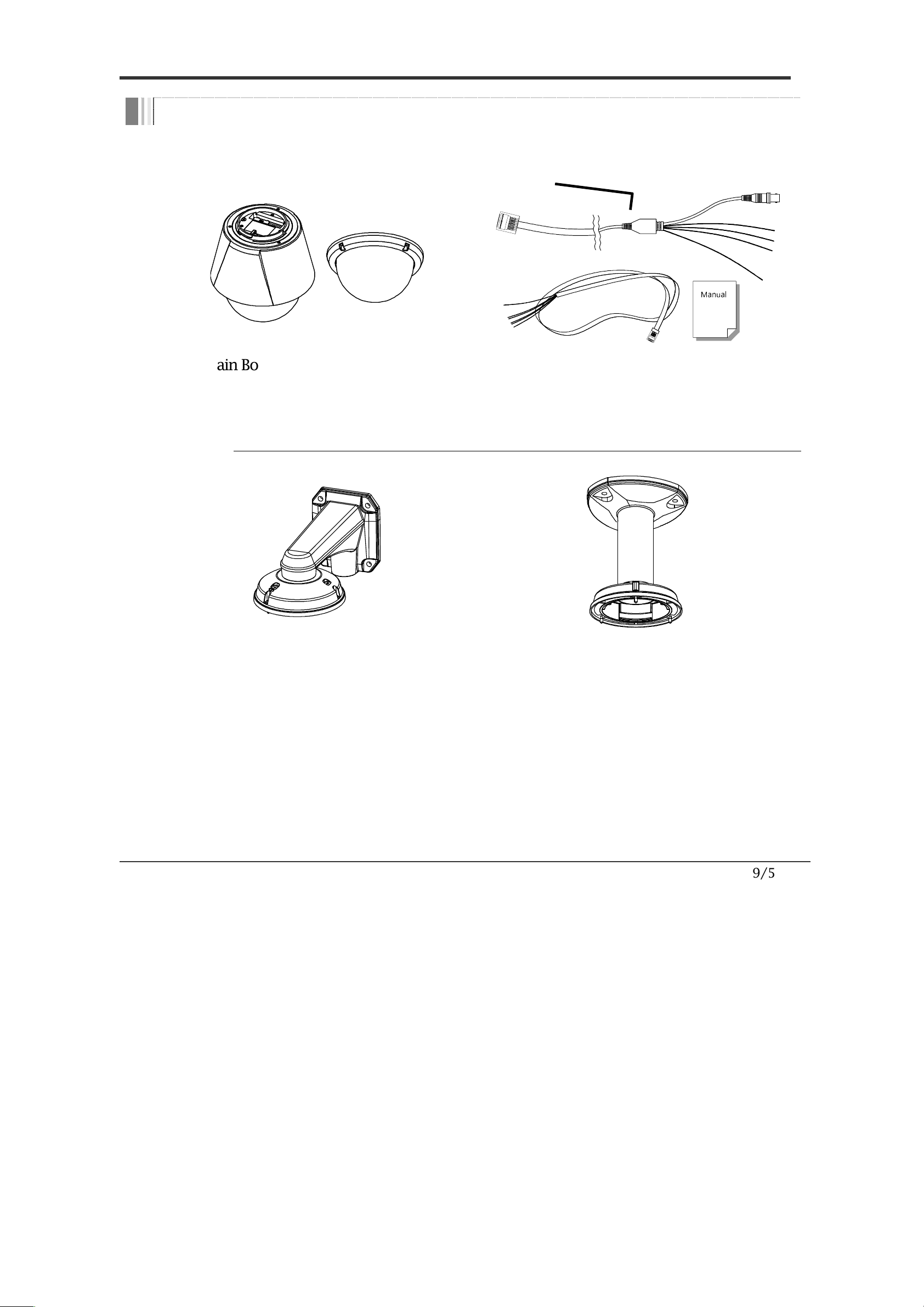
Package Component
Product & Accessories
Manual
Main Body & Surface Mount Bracket
Default Accessories
[Main Cable, I/O Cable ,Wrench, Owner’s
Manual
]
Brackets (Wall Mount Bracket is included but Ceiling Mount Bracket is optional)
Wall Mount Bracket
included in the
package
[Screws :
TORX Machine M4×L18
, Hex Lag
#14
×
50]
Ceiling Mount Bracket
(CLGMT37X) is
optional
[Screws :
TORX Machine M4×L18
, Anchor Bolt
3/8"
×
70]
I
NTRODUCTION
1
10/56
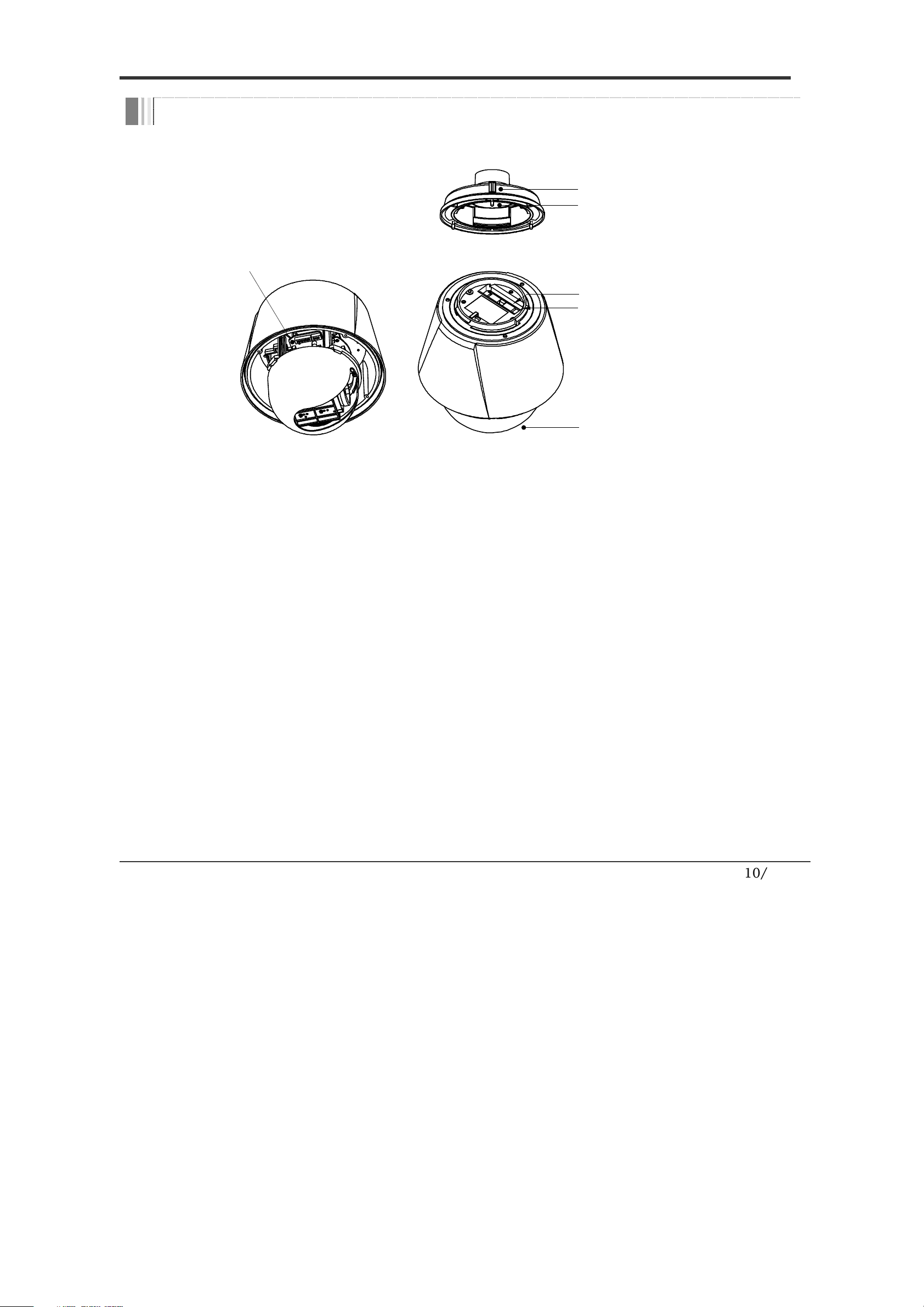
Main Part Description
DIP Switch
Main Connector
Sensor I/ O Port
Dome C ove r
Mounting Sc re w Hol e
Drop P re vention Sp rin g
Dome Cove
r
Do not detach the protection vinyl from the dome cover
before finishing all the installation process to protect the
dome cover from scratches or dust.
DIP Switch
Used to set up camera IDs and protocols.
Drop Prevention
Spring
This part keeps the c
amera from dropping during
installation and maintenance. After install the Bracket,
please, hang the spring to the drop prevention hook of main
body as shown in picture for further tasks.
Mounting Screw
Hole
Used to assemble the main body with a bracket
with screws.
Main Connector
Used for the power wire, the video cable and the RS
-
485
communication cable connection.
Sensor I/O Port
Used for the sensor in/out connection.
I
NTRODUCTION
1
11/56
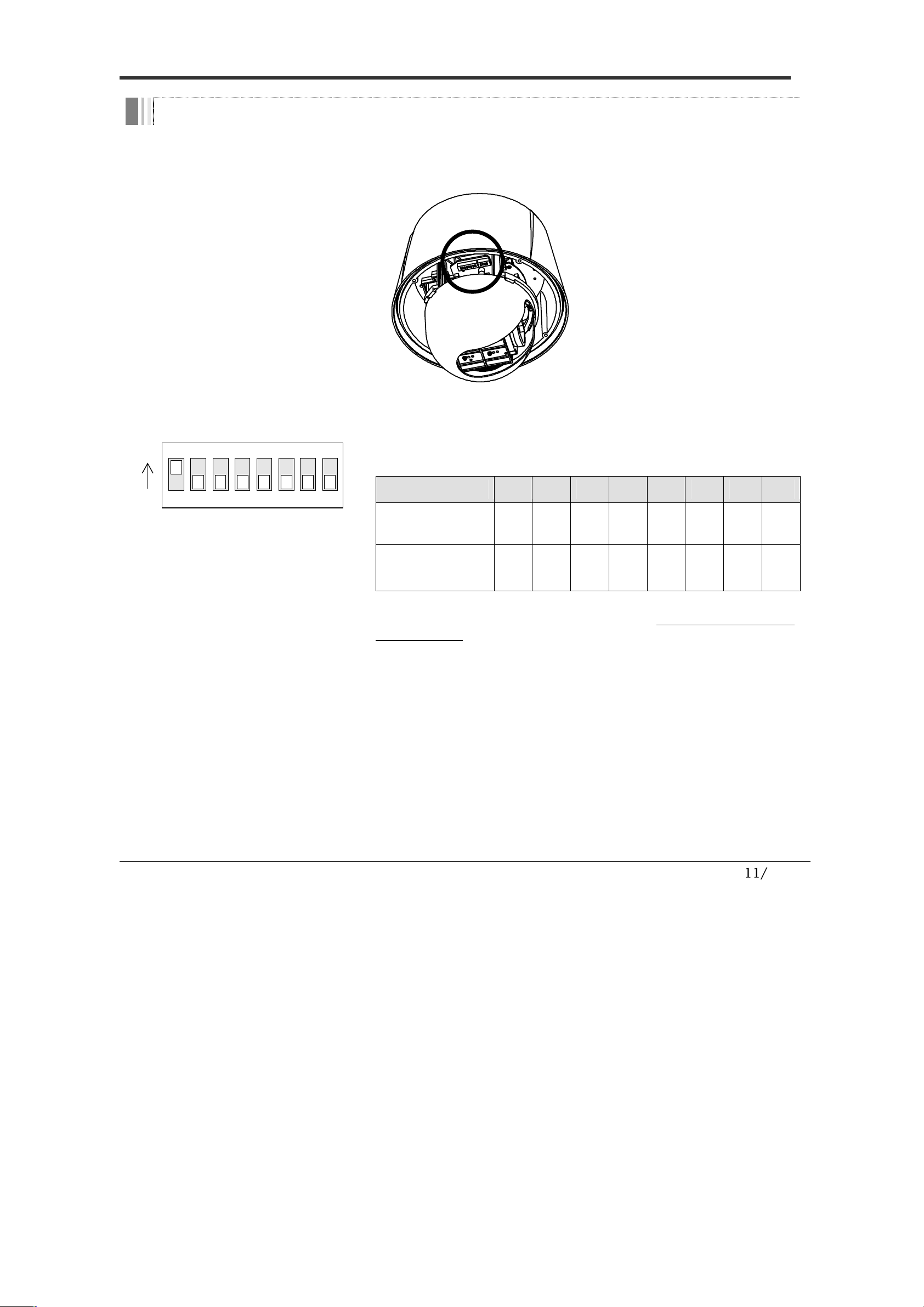
DIP Switch Setup
Before installing the camera, set
up the DIP swit
ch to configure
the
camera ID
and the communication protocol.
Camera ID Setup
ON
ON
1 2 3 4 5 6 7 8
ID numbers of cameras are set up with binary
numbers. See the examples shown below.
Pin
1
2
3
4
5
6
7
8
Binary Value
1
2
4
8
16
32
64
12
8
ex) ID=5
on
off
on
off
off
off
off
off
ex) ID=10
off
on
off
on
off
off
off
off
The camera ID range is “1~255”. Camera ID must
not be “0”!
The factory default of the camera ID is “1”.
Match the camera ID with the Cam ID setting of your
DVR or Controller to control the camera.
If you are connecting a single camera to a controller,
terminate the camera. When connecting more than
one camera to a single controller, terminate the last
camera on the communication line. The last camera
means the camera farthest in cable length from the
controller.
Note that the total length of the communication
INSTALLATION
2
12/56
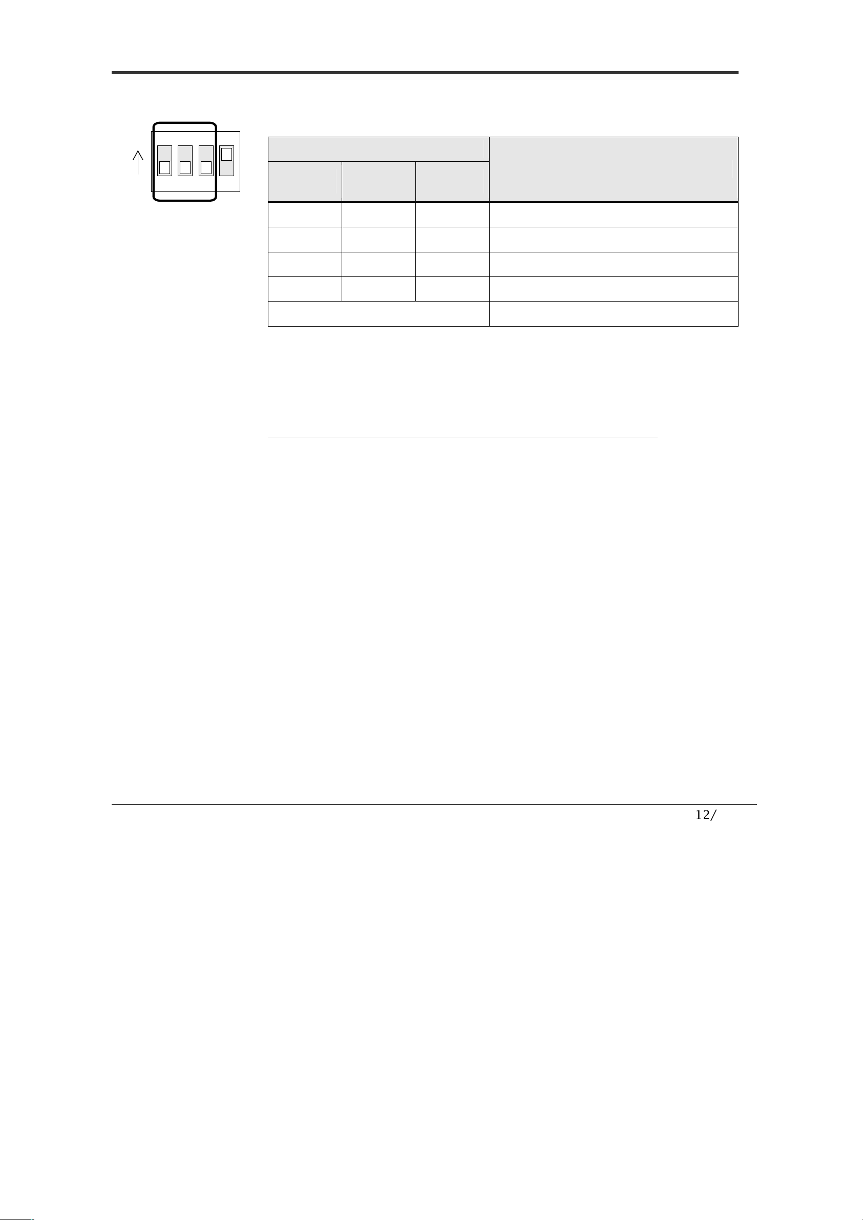
Communication Protocol Setup
1 2 3 4
ON
ON
Select an appropriate Protocol with the DIP switch combination.
Switch Mode
Protocol
P0
(Pin 1)
P1
(Pin 2)
P2
(Pin 3)
OFF OFF OFF PELCO-D, 2400 bps
ON OFF OFF PELCO-D, 9600 bps
OFF ON OFF PELCO-P, 4800 bps
ON ON OFF PELCO-P, 9600 bps
Others Reserved
Match the camera protocol with the camera protocol in the
setting of your DVR or controller to control the camera.
Adjust the DIP switch after turning off the camera. If you
changed the camera protocol by changing the DIP S/W, the
change will be effective after you reboot the camera.
The factory default protocol is “Pelco-D, 2400 bps”.
INSTALLATION
2
13/56
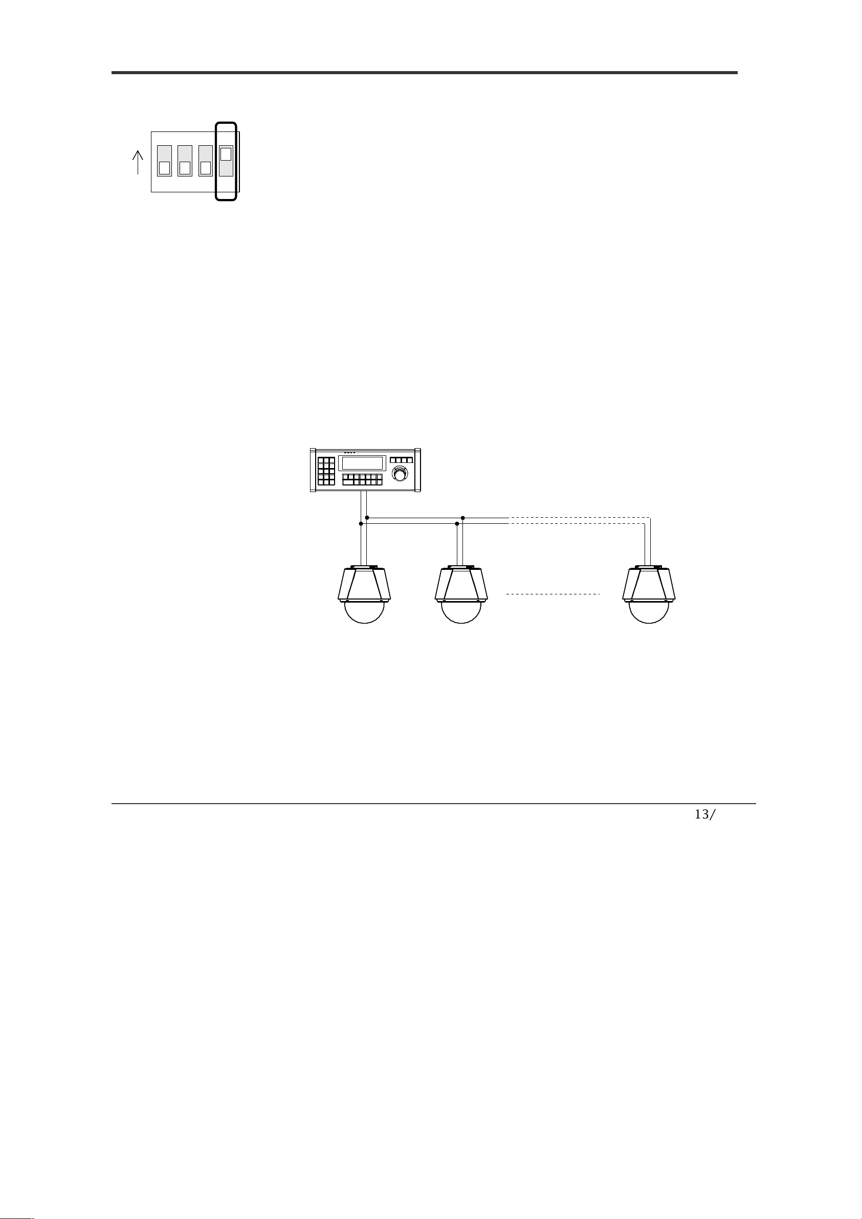
Terminal Resistor Setup
1 2 3 4
ON
ON
The terminal resistor is used for the following cases.
Case 1 : In case that the control cable length between a
camera and a controller is relatively very long (1:1
Connection)
If the communication cable length is very long, the electrical
signal will bound in the terminal point. This reflected signal
causes distortion of original signal. Accordingly, the camera can
be out of control. In this case, the terminal resistor of both sides
i.e. the camera and the controller must be set to ‘ON’ state.
Case 2 : In case that multiple cameras are connected to a
controller.
Due to similar reasons with the case 1, the terminal resister of
the controller and the last camera must be set to ‘ON’ state. The
last camera means the camera farthest in cable length from the
controller. Do not turn on the terminal resistor of all the
cameras on the same communication cable.
Contr oller
#1 #2 #n
Terminal Resistor ON
RS-485
Terminal Resistor
OFF
Terminal Resistor
OFF
Terminal Resistor
ON
INSTALLATION
2
14/56
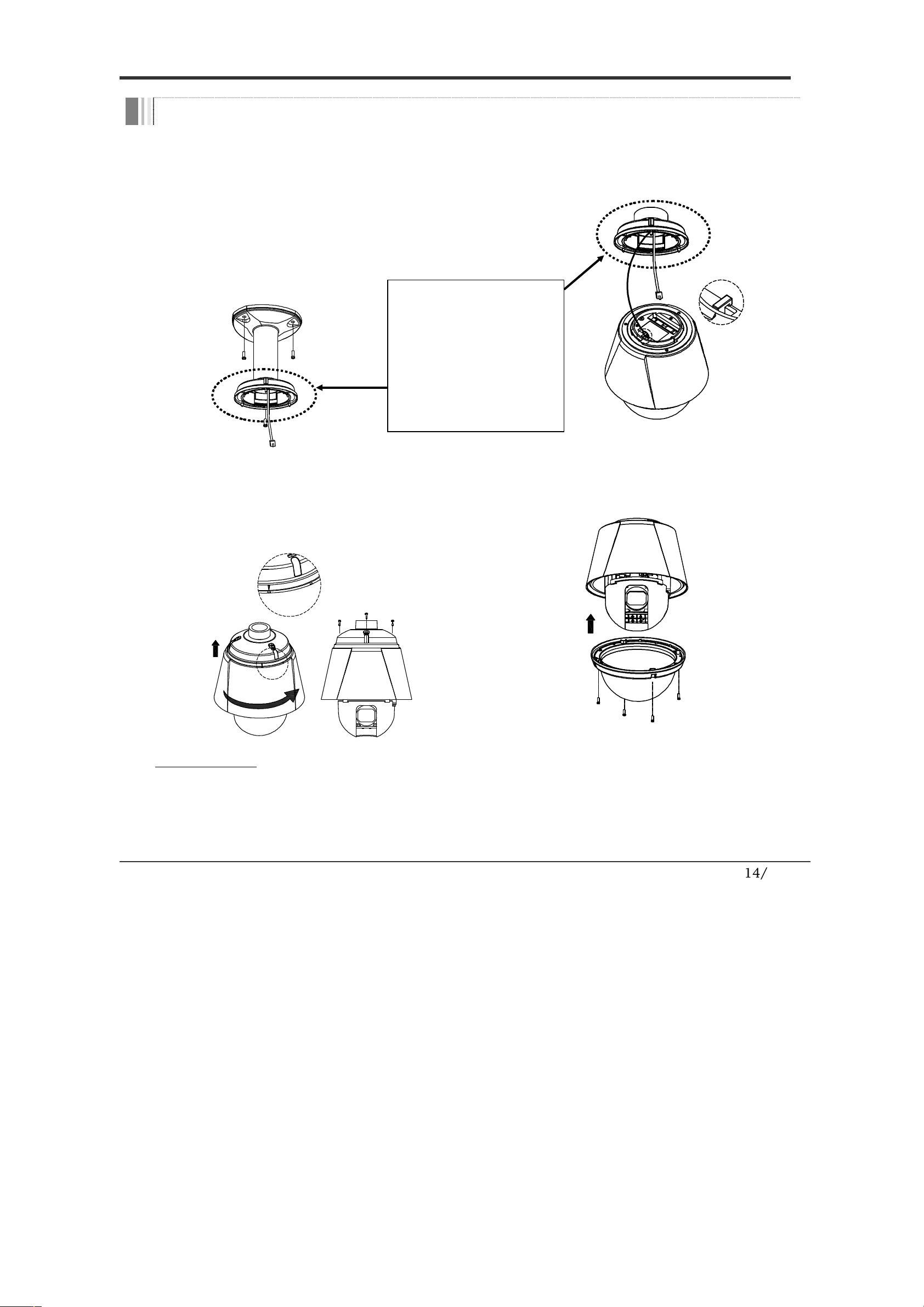
Installation with Ceiling Mount Bracket (Ver. 2.0)
①
Remove the ceiling tile from the
ceiling and cut a hole whose diameter
is 30~40mm on the ceiling tile to pass
the wire(s) and cable(s) through to the
upside of the ceiling. (In case of the
wiring and cabling through the
mounting surface only) Then prepare
the ceiling mount bracket. Pull the
wire(s) for the system as below.
(Anchor Bolt 3/8"
×70)
②
Hook up
“
Drop Prevention Spring
”
on main body to prevent camera from
unexpected drop and pull the wire(s)
and cable(s) for the system as below.
Spr ing Wi re Hoo k
③
L
ine up the mold lines and assemble
main body to mount adaptor and turn
it. And assemble the main body with
the camera mount adaptor with the 3
screws. (
TORX SCREW M4×18
).
END
START
④
Screw the dome cover to the main
body and remove the protection vinyl
from the dome cover.
Important Notice
Before starting the installation, make sure that the Camera ID and Protocol are set up properly.
To adjust the installation height from the mounting surface, the pipe and coupler should be needed between
the surface mount part of the ceiling mount bracket and the camera mount part of the ceiling mount bracket.
Note that they are not supplied by the manufacturer.
I
NSTALLATION
2
** Attention **
If you use the old
ceiling mount bracket,
please use the new
mounting adaptor
from the camera
package.
15/56
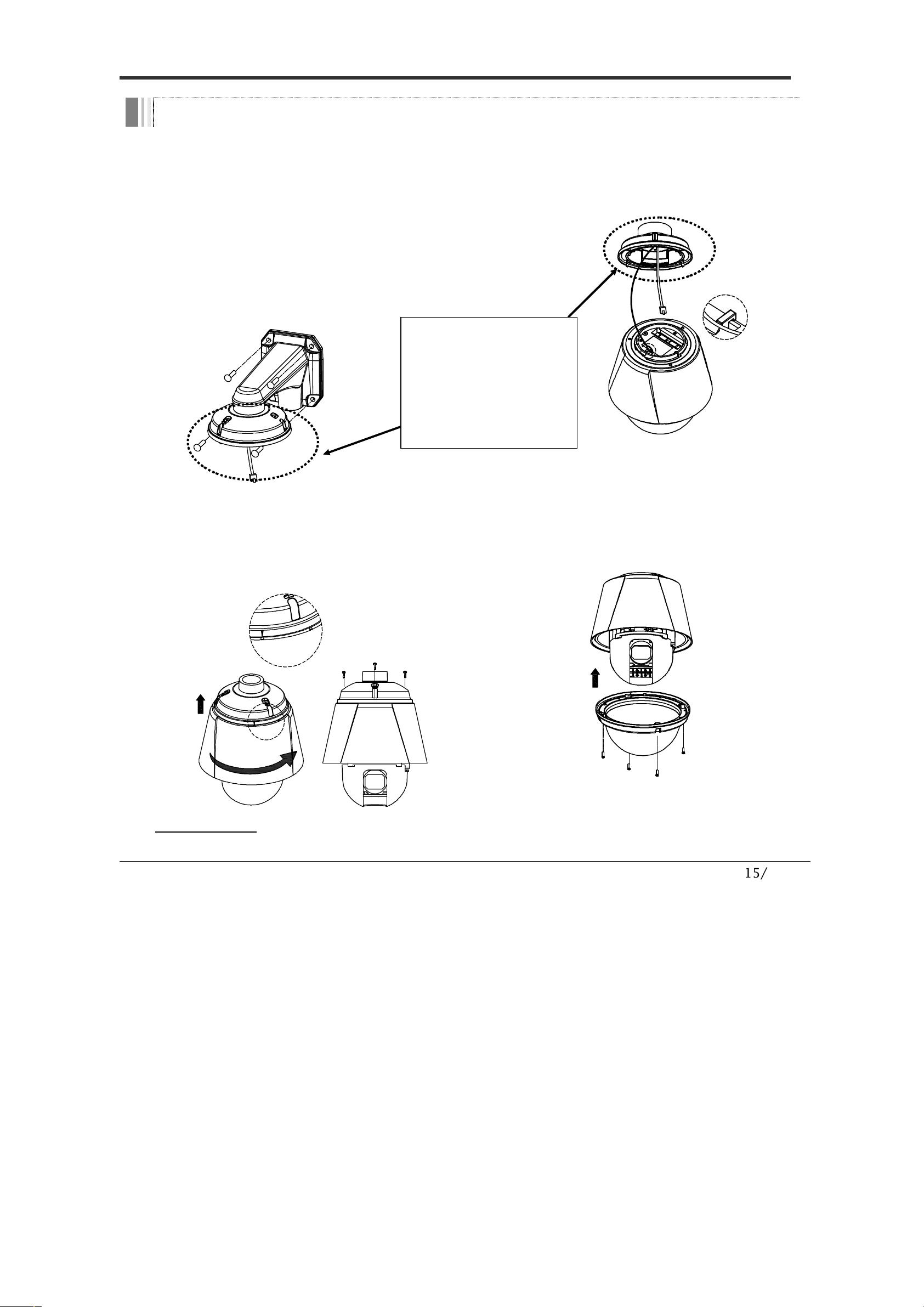
Installation with Wall Mount Bracket
①
Make a hole whose diameter is
30~40mm on the mounting surface to
pass the wire(s) and cable(s) through
the mounting surface. (In case of the
wiring and cabling through the
mounting surface only) Then prepare
the wall mount bracket. Pull the
wire(s) and cable(s) for the system as
below. Attach the wall mount bracket
to the mounting surface. (Hex Lag
#14
×50)
②
Hook up
“
Drop Prevention Spring
”
on main body to prevent camera from
unexpected drop and pull the wire(s)
and cable(s) for the system as below.
Spr ing Wi re Hoo k
③
Line up the mold lines and assemble
main body to mount adaptor and turn
it. And assemble the main body with
the camera mount adaptor with the 3
screws. (
TORX SCREW M4×18
).
END
START
④
Screw the dome cover to the main
body and remove the protection vinyl
from the dome cover.
Important Notice
Before starting the installation, make sure that the Camera ID and Protocol are set up properly.
INSTALLATION
2
** Attention **
If you use the old wall
mount bracket, please
use the new mounting
adaptor from the
camera package.
16/56
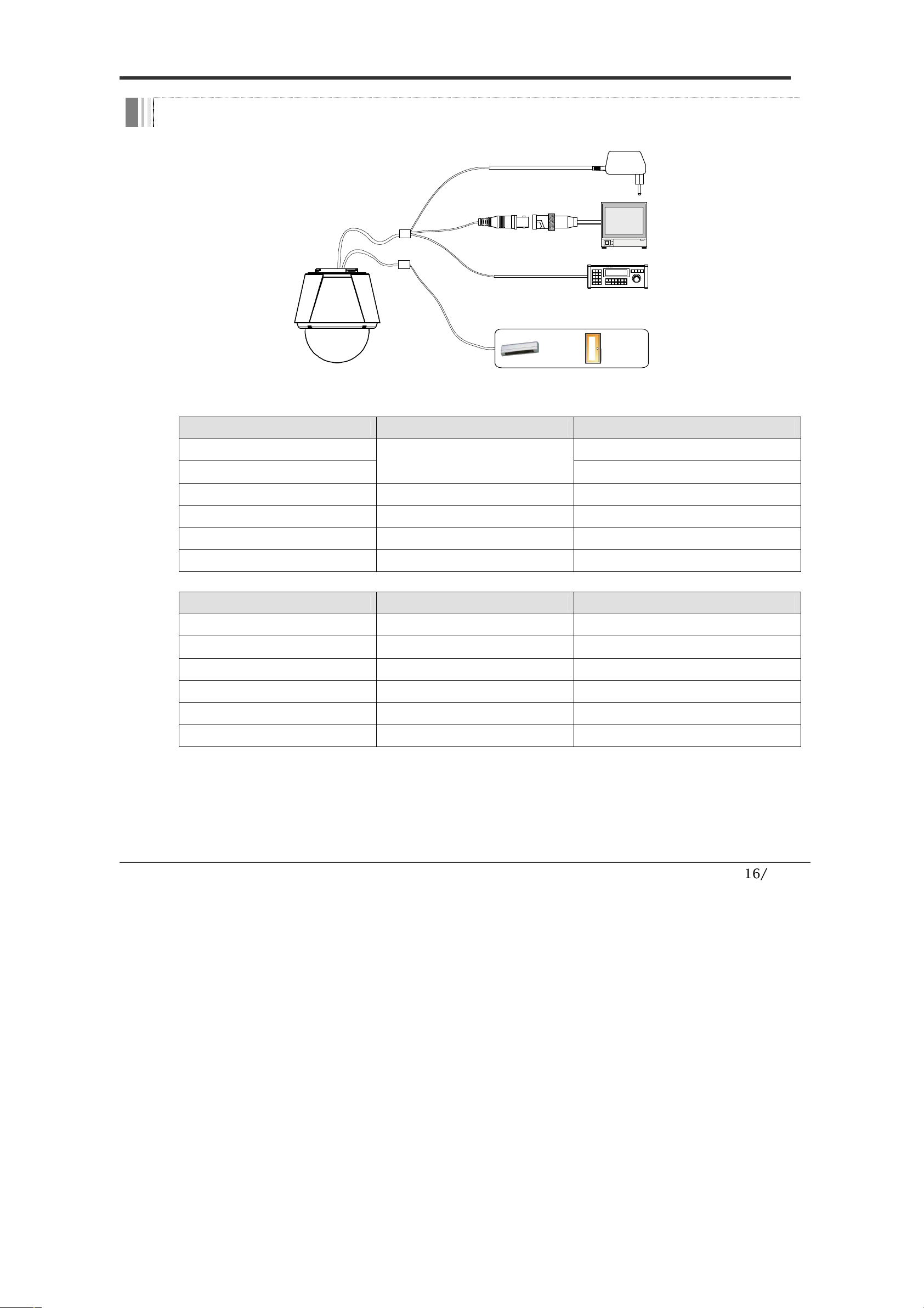
Wiring and Cabling
RS-485
BNC
SENSOR I/O
MAIN C ABLE
I/O CABLE
POWER
MONITOR
CONT ROLLER / DVR
IR
SENSOR
DOOR
SWITCH
Port Description
Main Cable
Port Pin Number
(RJ45)
Connect
or / Wire
Color
Signal
1
BNC Connector
Video +
2,4
Video
−
5
Red
RS
-
485 +
3
Yellow
RS
-
485
−
7
Orange
Power +
6,8
White
Power
−
I/O Cable
Port Pin Number
(RJ25)
Wire Color
Signal
1
Blue
IN COM
+
2
Yellow
IN 1
−
3
Green
IN 2
−
4
Red
IN 3
−
5
Black
OUT A
6
White
OUT B
INSTALLATION
2
17/56
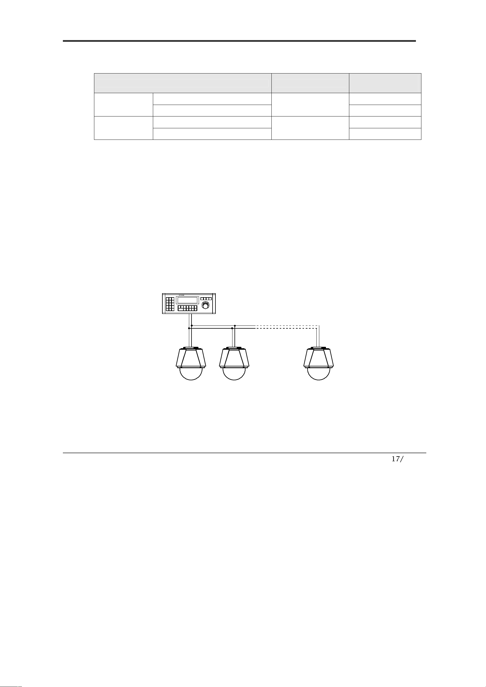
Power Description
Carefully check the voltage and current capacity of the rated power.
Model Input Voltage Range
Current
Consumption
DC12V Input
Without F
an & Heater
DC 11V ~ 18V
1.0 A
With Fan & Heater
1.8 A
AC24V Input
Without F
an & Heater
AC 17V ~ 29V
0.8 A
With Fan & Heater
1.8 A
For the DC input, be careful with the polarity of DC power. The system should
be permanentally damaged by wrong DC input.
In case that the length of the power wire is very long, there may be voltage
drop and the syatem may not work properly. Make the length of the power wire
as short as possible.
RS-485 Communication
For PTZ control, connect the cable(s) to your keyboard or DVR. To connect
multiple cameras to a single controller, RS-485 communication should be
connected in parallel as shown below. If you are connecting a single camera to
a controller, terminate the camera. When connecting more than one camera to
a single controller, terminate the last camera on the communication line. The
last camera means the camera farthest in cable length from the controller. Note
that the total length of the communication cable between a controller and the
camera(s) on the same communication line must be less than 1.2Km.
INSTALLATION
2
CONT ROLLER / DVR
RS-485
+
-
#1
+
-
#2
+
-
#n
+
-
 Loading...