

Page 1
®
633
Field Production Mixer with
Integrated Recorder
User Guide
Page 2
Legal Notices
Manual Conventions
Product specications a nd f eatures a re s ubject to
change without prior notification.
Copyright © 2018 Sound Devices, LLC. All
rights reserved.
This product is subject to the terms and conditions
of a software license agreement provided with the
product, and may be used in accordance with the
license agreement.
This document is protected under copyright law. An
authorized licensee of this product may reproduce
this publication for the licensee’s own personal use.
This document may not be reproduced or distributed, in whole or in part, for commercial purposes,
such as selling copies or providing educational services or support.
This document is supplied as a technical guide. Special care has been taken in preparing the information
for publication; however, since product specications
are subject to change, this document might contain
omissions and technical or typographical inaccuracies. Sound Devices, LLC does not accept responsibility for any losses due to the user of this guide.
Trademarks
The “wave” logo and USBPre are registered
trademarks; FileSafe, PowerSafe, SuperSlot,
MixAssist, and QuickBoot are trademarks of Sound
Devices, LLC. Mac and OS X are trademarks of Apple
Inc., registered in the U.S. and other countries. Windows and Microsoft Excel are registered trademarks
of Microsoft Corporation in the U.S. and other countries. All other trademarks herein are the property of
their respective owners.
Symbol Description
>
+
i
⚠
This symbol is used to show the order
in which you select menu commands
and sub-options, such as: Main Menu
> Audio indicates you press the Menu
button for the Main Menu, then scroll to
and select Audio by pushing the Control
Knob.
A plus sign is used to show button or
keystroke combinations.
For instance, Ctrl+V means to hold the
Control key down and press the V key
simultaneously. This also applies to
other controls, such as switches and
encoders. For instance, MIC+HP turn
means to slide and hold the MIC/TONE
switch left while turning the Headphone
(HP) encoder. METERS+SELECT means
to hold the METERS button down as you
press the SELECT encoder.
A note provides recommendations and
important related information. The text
for notes also appears italicized in a different color.
A cautionary warning about a specic
action that could cause harm to you,
the device, or cause you to lose data.
Follow the guidelines in this document
or on the unit itself when handling electrical equipment. The text for cautionary notes also appears italicized and
bold in a dierent color.
FCC Notice
This device complies with part 15 of the FCC Rules.
Operation is subject to the following two conditions:
(1) This device may not cause harmful interference,
and (2) This device must accept any interference
received, including interference that may cause
undesired operation.
FCC Part 15.19(a)(3)
www.sounddevices.com
support@sounddevices.com
633 User Guide • Rev 4-D • July 10, 2018
This document is distributed by Sound Devices, LLC
in online electronic (PDF) format only. E-published
in the USA.
Sound Devices, LLC
E7556 Road 23 and 33
Reedsburg, Wisconsin 53959 USA
Direct: +1 (608) 524-0625
Toll Free: (800) 505-0625
Fax: +1 (608) 524-0655
Page 3
Revision History
This table provides the revision history and cross-reference links to “what’s new” in this guide.
Rev# Date Firmware
Version
1-A Feb 2016 v2.11 Initial Ocial Release of Redesigned Publication
1-B Apr 2016 v2.11 Minor document edits; x broken cross-ref links.
3-A June 2016 v3.10 Includes Firmware feature updates for:
3-B July 2016 v3.10 Minor document edits: x page-numbering realignment.
4-A Sept 2016 v4.00 Added new chapter “Wingman” covering how to use the
4-B Feb 2017 v4.50 Added new chapter “MixAssist & Dugan Automixing” covering the
4-C Apr 2017 v4.51 Updated Wingman chapter with information on Wingman
Description
Includes Firmware feature updates for:
• CL-12 Integration: “CL-12 Linear Fader Controller” on page
151
• External TC User Bits: “Setting User Bits” on page 79
• QR Codes: “Viewing User Guide via Smart Phone QR Code” on
page 106
• Added new chapter on Remote Control of 6-Series mixers.
• In CL-12 chapter, added new section “Disabling Output Con-
trols” on page 165.
• In File Storage chapter, added new section “Changing the Take
Designator” on page 88.
Wingman iOS-based app that, when paired with the WM-Connect
Bluetooth® Smart USB dongle, enables remote control of any
6-Series mixer.
new Auto Mixer feature added to the 633.
Password.
3
Page 4

User Guide
4
Page 5

Table of Contents
Overview of Chassis
Front Panel ......................................9
Left Side Panel ..................................12
The LCD and User Interface
Meter Views ....................................15
Using Meter Views ............................16
Customizing Meter Views ......................16
Headphone Monitoring
Connecting Headphones .........................19
Selecting Headphone Source .....................19
Setting Headphone Encoder Mode ................20
Configuring the Headphone Preset List. . . . . . . . . . . . . 20
Power
Powering the 633 ...............................23
Using External Power ..........................23
Using Battery Power ..........................24
Voltage Ranges and Thresholds ...................24
Configuring Power Settings ......................25
Right Side Panel ................................12
Back Panel .....................................13
Accessing the Main Menu ........................17
Customizing the LCD and LEDs ....................18
Using LCD Daylight Mode ......................18
Defining Custom Headphone Presets ............21
Choosing a Favorite Headphone Preset ..........22
Using Headphone Source Shortcuts ................22
Headphone Peak LED ............................22
PowerSafe .....................................26
QuickBoot .....................................27
Forcing Power Off (Optional) .....................27
Power Consumption .............................27
Inputs
Physical Input Controls ...........................29
Activating an Input ..............................30
Accessing the Input Setting Screens ................30
Setting Input Source ...........................32
Setting Input High-Pass Filters ..................33
Setting L, R, X1, and X2 Routing ................33
Using a Track Name Shortcut ...................34
Inverting the Phase ...........................35
Outputs
Output Connections .............................41
Adjusting Output Gain ...........................41
Accessing Output Settings ........................42
Configuring Output Linking ......................43
Setting Output Type and Nominal Level ............43
Output Routing .................................44
MixAssist & Dugan Automixing
Auto Mixer Screen ..............................49
Turning the Auto Mixer On or Off ...............50
Assigning Inputs to the Auto Mixer ..............51
Overview of MixAssist ...........................51
Adjusting Trim and Fader Controls .................35
Adjusting Pan ..................................36
Accessing Input Settings ..........................36
Configuring Linking ...........................37
Configuring Phantom Voltage ..................38
Configuring the PFL Toggle Mode ...............38
Configuring Input to ISO Routing ...............39
Configuring Input Delay .......................40
Accessing AES Output Routing Screen ...........44
Accessing Aux (X1 - X4) Routing Screens ..........45
Configuring Playback to Outputs ..................47
Adjusting Output Delay ..........................47
Sending Tone to Outputs .........................48
Setting MixAssist Off-Attenuation ...............52
LCD Views During MixAssist Automixing .........53
Overview of Dugan Automixing ...................54
LCD Views During Dugan Automixing ...........54
5
Page 6

User Guide
Limiters
Overview ......................................57
Enabling the Limiters ............................58
Recording
Using Media ....................................61
Using the Transport Control ......................62
Arming or Disarming Recording Tracks .............63
Accessing Recorder Settings ......................64
Setting File Type and Media Track Assignment ......65
WAV (Broadcast WAV) .........................65
MP3 ........................................65
Changing the MP3 Bit Rate .......................66
Slate Mic and Return
Disabling the Slate Microphone ...................71
Setting Slate Mic Gain ...........................72
Routing the Slate Mic ............................72
Timecode
Timecode ......................................75
Setting the Timecode Mode ....................76
Setting the Frame Rate ........................77
Setting Timecode Hold Off .....................77
Adjusting the Threshold .........................58
Linking Limiters .................................58
Setting the Sample Rate .........................66
F Sample Modes ..............................67
Setting the Bit Depth ............................67
Setting the Pre-roll ..............................68
Using the Slate Microphone ......................68
Playing Back Active Takes ........................69
Viewing Approved Media List via Smart Phone ......69
Using the Slate for Notation ......................73
RTN Monitoring ................................73
Jamming the Timecode ........................78
Setting the Timecode Generator ................78
Setting User Bits ..............................79
Setting Display Mode ..........................80
File Storage
File Structure ...................................81
Transferring Files to PC ...........................82
Take List and File List ............................82
Accessing the File List ..........................83
Deleting Files or Folders .......................84
File Storage Settings .............................84
Setting Folder Options ...........................86
Generating Sound Reports .......................87
Metadata and Take List
Take List Overview ..............................93
Accessing the Take List .........................94
Playing Takes ...................................94
Editing Metadata on the 633 .....................94
Using the Phrase List for Notes ....................95
System
Setting up Tones and Bells ........................99
Configuring Record/Stop and Warning Bells .....100
Configuring the Meters .........................101
Setting Meter Ballistics and Peak Hold ..........102
Setting Peak Hold ............................103
Setting up Date and Time Parameters .............103
Changing the Take Designator ....................88
Defining File Max Size ...........................88
Setting Scene Increment Mode ....................88
Setting Take Reset Mode .........................89
Setting File Playback Mode .......................89
Selecting a Default Playback Card .................90
Erasing / Formatting Media .......................90
Clearing Scene List ..............................96
Metadata Overview .............................97
Renaming or Deleting Previous Takes ..............98
Editing Metadata in Other Programs ...............98
Calibrating Faders & Pans .......................105
Using a USB Keyboard ..........................106
Viewing Shortcut Information ...................106
Viewing User Guide via Smart Phone QR Code .....106
Viewing Version Information ....................107
Updating Firmware ............................107
6
Page 7

Quick Setup
Saving Settings ................................109
Copying Quick Setup Files .....................110
Deleting Quick Setup Files ....................110
Loading Previously Saved Settings ................111
Shortcuts
Front Panel Shortcuts ...........................113 USB Keyboard Shortcuts ........................115
Wingman Integration: 6-Series
Starting Wingman .............................117
Setting up Wingman Password ...................117
User Interface .................................118
Transport View ................................120
Connecting to a 6-Series Mixer .................121
Using Transport Controls ......................123
Designating Circle and False Takes ..............123
Using Meter Views ...........................124
Editing Track Names ..........................125
Arming/Disarming Tracks ......................126
Take List View .................................127
Editing a Take’s Metadata .....................128
Reports View ..................................129
Creating Sound Reports .......................131
About View ...................................131
Track View on iPhone or iPod Touch ..............132
Third-Party Remote Control
Control in the Palm of Your Hand ................135
iOS Remote Control Connection Diagrams .......137
iOS Remote Control Examples .................138
Web-based Wireless Remote Control ..............139
Web-based Remote Control Connection Diagrams 140
Web-based Remote Control Examples ..........141
Specifications
Analog Inputs .................................143
Digital Inputs ..................................144
Analog Outputs. . . . . . . . . . . . . . . . . . . . . . . . . . . . . . . . 144
Digital Outputs/Recorder .......................145
Accessories
Electronic Accessories ...........................147
Cables and Connectors ..........................148
CL-12 Linear Fader Controller
Overview of Panels ............................151
Top: EQ & OUTPUTS Sections ..................154
Left: Channel Strip Section ....................155
Right: Buttons and HP Encoder ................157
Altered Functionality ...........................159
Feature Comparison Chart ....................159
CL-12 Sub-menu .............................160
Selecting One or More Input Channels ............161
Activating PFL of an Input .......................162
Setting SEL to follow PFL ......................162
Trim Level Adjustment on 6-Series ................162
Adjusting Trim Levels (688 only) ................163
Adjusting Trim Levels (664 only) ................163
Adjusting Trim Levels (633 only) ................163
Routing Input Channels .........................164
Adjusting Output or Track Levels .................164
Timecode and Sync .............................145
Power ........................................146
Environmental ................................146
Dimensions and Weight ........................146
Cases .........................................149
Software ......................................150
Configuring Output Meters (688 only) ..........165
Disabling Output Controls .......................165
Arming L, R, X1, X2 Tracks .......................165
Using the 3-Band Equalizer (688 only) .............166
Accessing the EQ Submenu ....................167
Bypassing EQ ................................169
Setting the Q-Factor ..........................169
Setting LF and HF Frequency Defaults ...........170
Setting LF and HF Filter Types ..................170
Setting EQ Routing ...........................171
Using High-pass Filters ..........................171
Naming Tracks .................................171
Configuring User Programmable Buttons ..........172
Adjusting CL-12’s LED Brightness .................173
Specifications ..................................173
7
Page 8

User Guide
CS-633
Features ......................................175 Specifications ..................................175
Software License
8
Page 9
Overview of Chassis
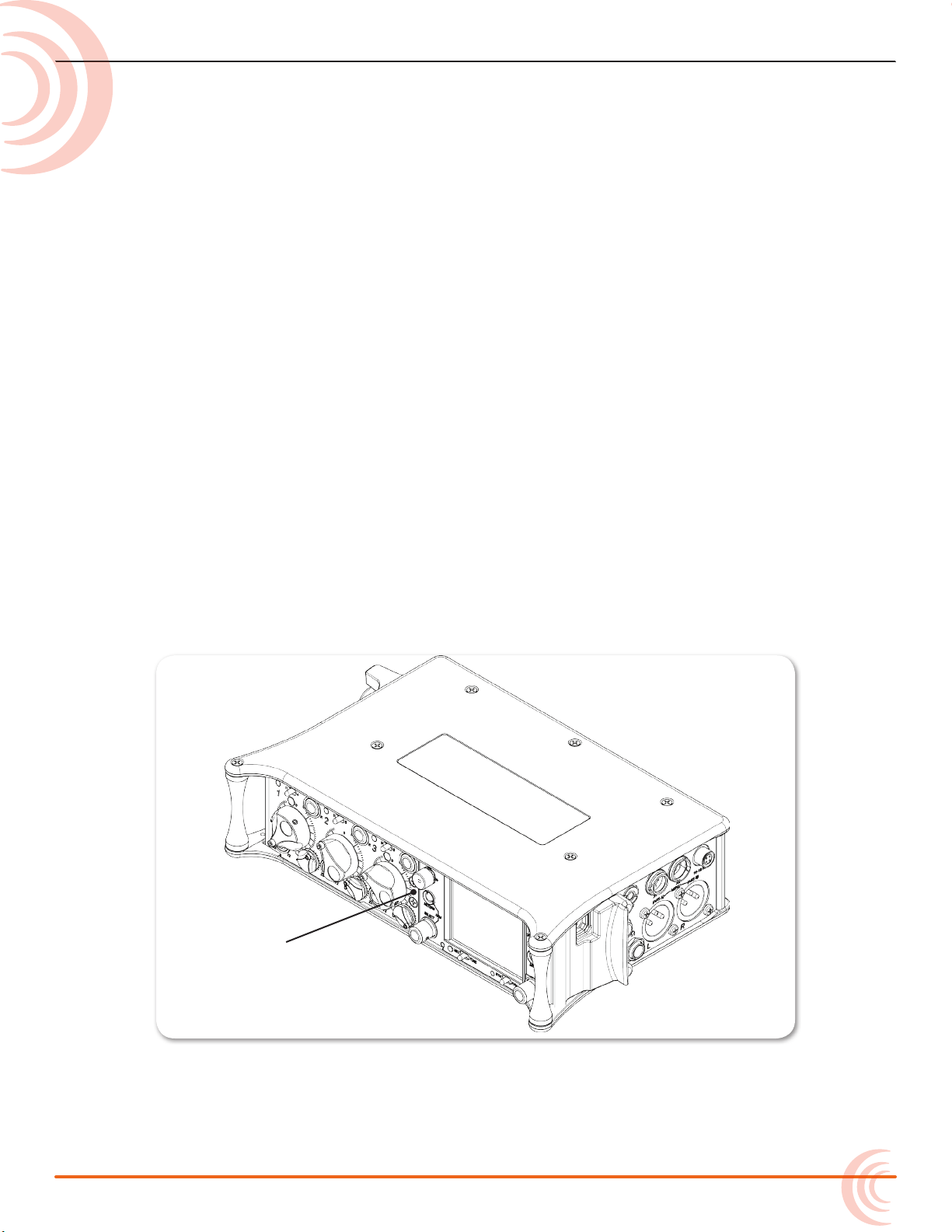
Front panel
The 633 chassis is made of light-weight
and durable metal.
The front panel of the chassis features
several easy-to-reach controls,
switches, LEDs, and a sunlight-visible
LCD screen.
Its side panels provide a variety of
connection options for ultimate I/O
exibility, and the back panel has
battery mounts for ultimate portability.
Front Panel
Topics in this section include:
Front Panel
Left Side Panel
Right Side Panel
Back Panel
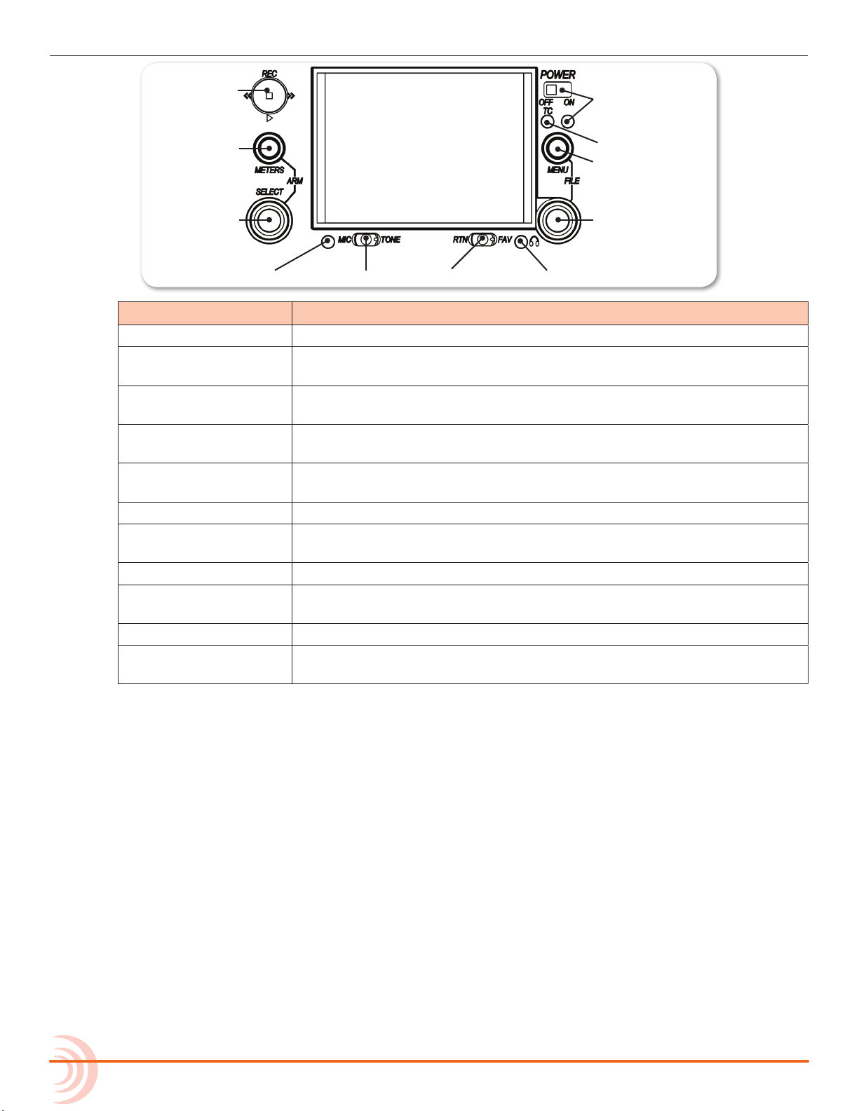
The front panel provides the LCD as well as several buttons, switches, and
controls as dened in the following tables.
9
Page 10
User Guide
Power Switch and LED
Menu Button
Headphone Encoder
Headphone Clipping LED
RTN/FAV SwitchMIC/TONE Switch
Slate/Tone LED
Select Encoder
Meters Button
Transport Control
Timecode LED
Power Switch and LED Powers 633 on and o, and indicates power status.
Timecode LED Flashes blue to indicate whether the internal timecode generator (and
Menu Button Provides access to the Main menu. Also used for various shortcut
Headphone Encoder Adjusts headphone level and monitor source. Also used for various
Headphone
Clipping LED
RTN/FAV Switch Toggles monitor source. Also used for various shortcut functions.
MIC/TONE Switch Toggle slate mic and tone generator. Also used for various shortcut
Slate/Tone LED Indicates slate mic is active or tone generator is locked on.
Select Encoder Multiple purpose rotary encoder. Also used for various shortcut
Meters Button Cycles between meter views. Also used for various shortcut functions.
Transport Control Controls playback and recording. Also used for various shortcut
Feature Description
QuickBoot) is active while the mixer is o.
functions.
shortcut functions.
Illuminates red to indicate headphone output is approaching clipping
level.
functions.
functions.
functions.
10
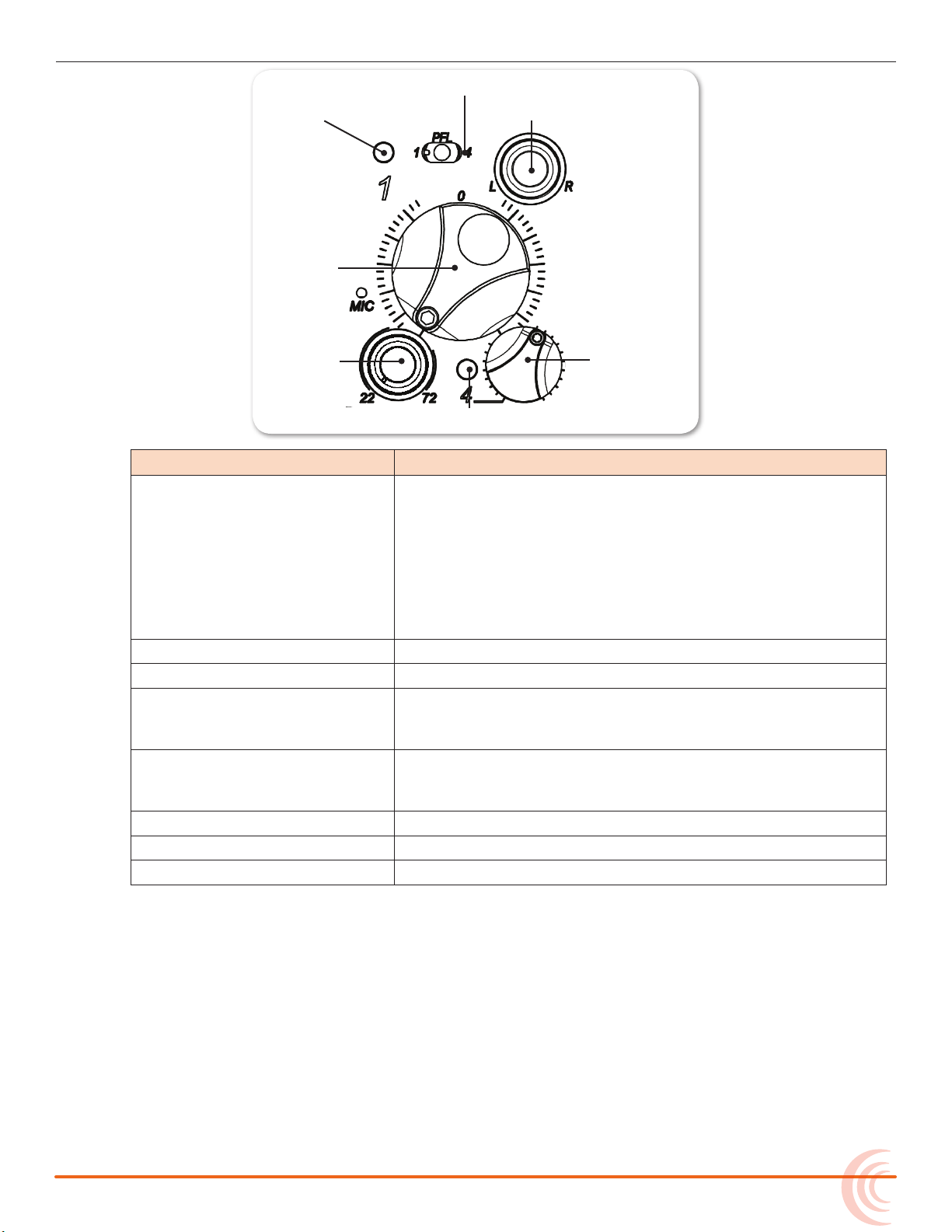
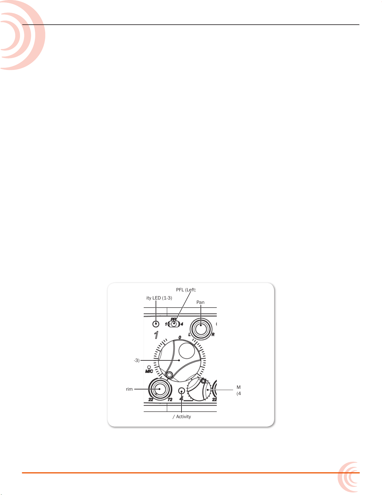
Also on the front panel, there are three sets of controls related to inputs, such
as pans, faders, and trims.
Page 11
OVERVIEW OF CHASSIS
Fader (1-3)
Pan (1-3)
PFL (Left: 1-3, Right: 4-6)
Trim (1-3)
PFL status / Activity LED (4-6)
PFL status / Activity LED (1-3)
Mini-Fader (4-6)
Feature Description
PFL Switch By default, this switch has dual-functionality. It activates
Pre-Fade Listen (PFL) and displays Input Settings screen for
input 1-3 (slide left) and 4-6 (slide right). Slide again to deactivate. The functionality of this switch may be altered via
the Main menu’s Inputs > PFL Toggle Mode.
Fader (1-3) Adjusts fader level for inputs 1-3.
Mini-Fader (4-6) Adjusts fader level for inputs 4-6.
Trim (1-3) Adjusts trim level for inputs 1-3. Trim levels for inputs 4,
Pan (1-3) Adjusts pan between L and R tracks. Inputs 4, 5, and 6 are
PFL status / Activity LED (1-3) Indicates PFL status and input signal activity.
PFL status / Activity LED (4-6) Indicates PFL status and input signal activity.
MIC The slate microphone.
Does not aect Master Output signal. For momentary action, hold the switch for one second or longer. The input LED
ashes yellow when an input’s PFL is active.
5, and 6 are controlled via their respective Input Settings
screens.
routed to the L and R mix via their respective Input Settings
screens.
11
Page 12
User Guide
Battery Compartment
XLR Inputs
TA3 Inputs Headphone Output
RTN Input
SD Card Slot
CompactFlash SlotUSB B Connector
Timecode I/O
DC Input
Main OutputsHeadphone
X1, X2 Outputs
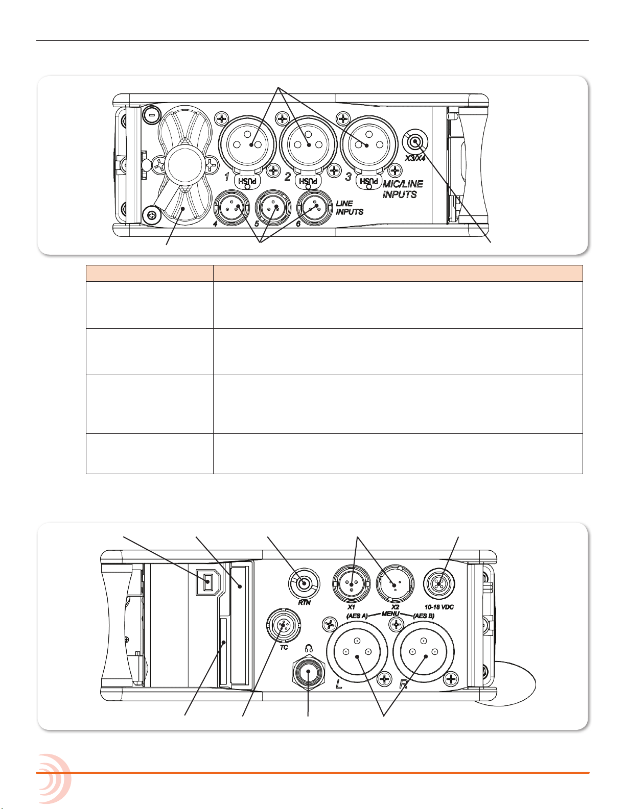
Left Side Panel
Feature Description
XLR Inputs (1-3) Active-balanced analog microphone- or line-level inputs. Input 1 can
TA3 Inputs (4-6) Active-balanced analog line-level inputs.
also accept AES3 or AES42 (Mode 1) signal.
Pin-1 = ground, pin-2 = hot (+), and pin-3 = cold (-).
X3/X4 Output Multi-purpose auxiliary analog output. Two channels on unbalanced
Battery Compartment Holds six AA (LR6) batteries for backup powering. NiMH rechargeable
Right Side Panel
Pin-1 = ground, pin-2 = hot (+), and pin-3 = cold (-). Float pin 3 to
unbalance.
3.5mm TRS connection. Level can be adjusted from -30 dB (mic level) up to 0 dB (sucient for driving headphones).
Tip = left, ring = right, and sleeve = ground.
cells advised. Top row inserted with negative (-) end facing out; Bottom row inserted with positive (+) end facing out.
12
Page 13
OVERVIEW OF CHASSIS
Battery Mounts
Feature Description
USB B Connector Factory use and keyboard connection (with adapter).
CompactFlash Slot Accepts approved CompactFlash cards with the label-side toward the
rear of the mixer. Compatible with Type I and Type II cards. Highspeed UDMA cards are recommended for higher track count recording.
RTN Input Unbalanced stereo 3.5 mm female connector for Return audio input.
Sleeve = ground, tip = left, ring = right.
X1, X2 Outputs Line, -10, or Mic level selected in Main menu OUTPUTS section.
(Pin 1 = Ground, pin 2 = Hot (+), pin 3 = Cold (-))
Float pin 3 to unbalance.
DC Input Accepts DC voltages from 10–18 V for powering.
(Pin 1 = Negative (–), pin 4 = Positive (+))
SD Card Slot Accepts SD/SDHC/SDXC cards with the notched corner oriented to-
ward the top of the 633. High speed class 10 cards are recommended.
Insert until it clicks securely in the slot. The card should glide smoothly
into the slot. Press to eject.
Timecode I/O Timecode input and output on 5-pin LEMO® connector.
Headphone Output A 1/4” TRS headphone output. Can drive headphones from 8 to 1000
ohm impedances to very high levels.
Main Outputs Transformer-balanced analog outputs on standard 3-pin XLR-3M con-
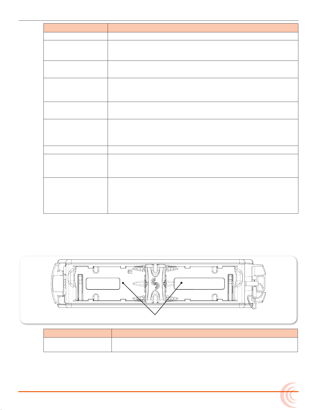
Back Panel
The back panel provides additional powering options for the 633 with two L-type
mounts for Lithium Ion batteries (not included):
Tip = left, ring = right, and sleeve = ground.
nectors. Can be set to send AES3 digital signals (1,2 and 3,4 on L and
R respectively) in Main menu OUTPUTS section.
(Pin 1 = Ground; pin 2 = Hot (+); pin 3 = Cold (-))
Unbalance by grounding pin 3 to pin 1.
Feature Description
Battery Mounts Battery mounts (B1 and B2) on the 633’s back panel are compatible
with Sony® L-Series batteries. Any capacity supported.
13
Page 14

User Guide
14
Page 15
The LCD and User Interface
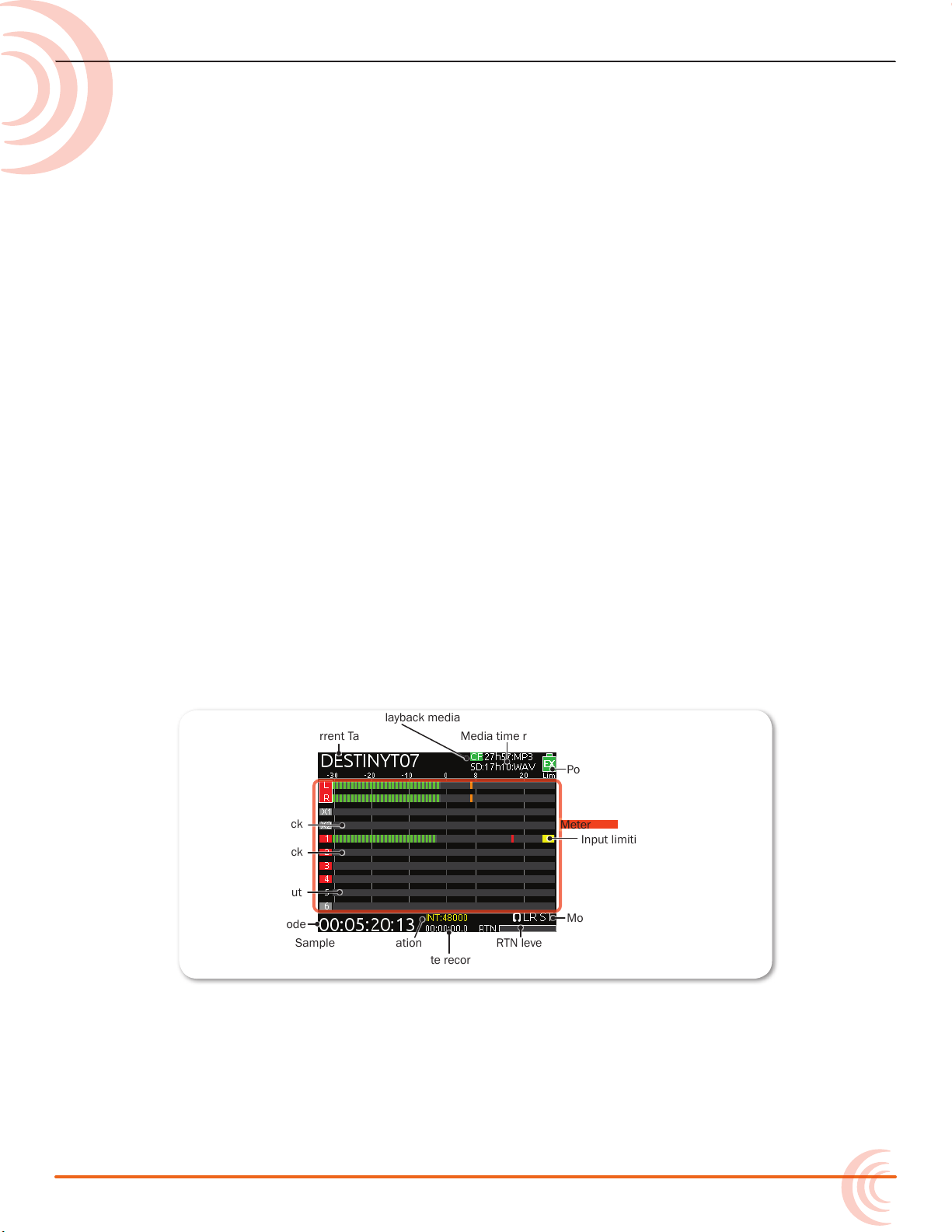
Current Take
Active playback media
Media time remaining and audio le format
Power source and level
Unarmed track
Monitor (Headphone) information.
RTN levelSample rate information
Absolute recording time
SMPTE timecode
Powered off input
Armed track
Input limiting activity
Meter View
The LCD display is the primary source
of information when operating the 633.
All settings are congured via the LCD
display. All signal level meters can be
displayed on the LCD display.
This chapter describes meter views,
including the Main screen which is
displayed when no other screens
are active, the Main menu, and LCD
Daylight mode.
Other screens, such as the Input
Settings screen, are described where
applicable throughout the guide.
Meter Views
The 633 displays important metering information at a glance on its LCD. All
meter views provide various combinations of input, track, and return meters. By
default, the rst of three predened meter views is shown. This view is known
as the Main screen.
Topics in this section include:
Meter Views
Using Meter Views
Customizing Meter Views
Accessing the Main Menu
Customizing the LCD and LEDs
Using LCD Daylight Mode
The three predened meter views are:
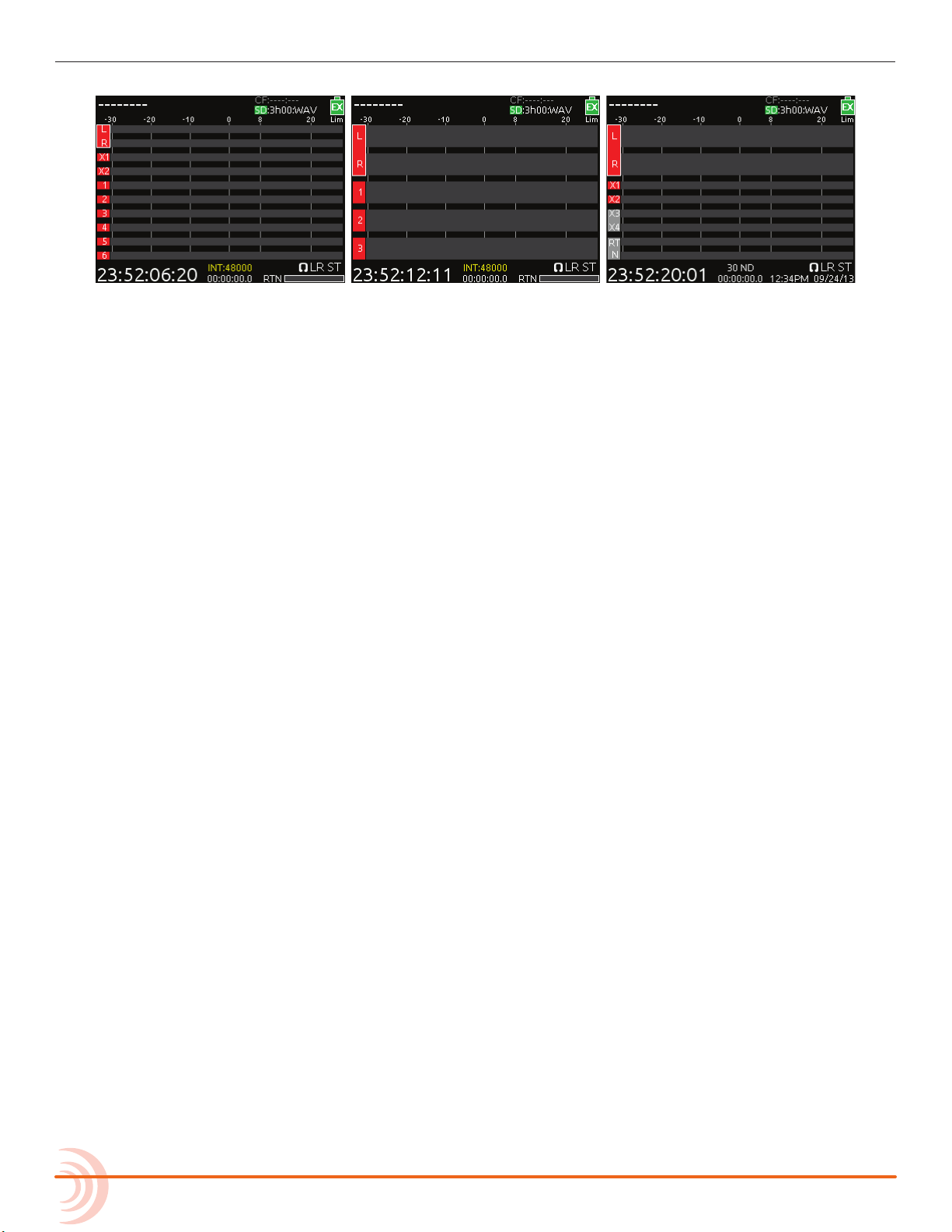
• LR, X1, X2, 1-6 — This meter view (shown above) shows left, right, X1, and
X2 bus tracks as well as all 6 input tracks.
• LR, X1-X4, RTN — This meter view shows left, right, X1, and X2 bus tracks,
plus signal from X3, X4, and return.
• LR, 1-3 — This meter view shows left and right bus tracks as well as signal
from inputs 1-3.
15
Page 16
User Guide
The following images show all three predened meter views.
i The time and date is displayed in place of the small RTN meter on the LR, X1-X4,
RTN meter view. Also, a fourth conguration (not shown) with only LR and inputs
1-6 is available as a display option for meter views.
Using Meter Views
Although the rst meter view is known as the Main screen, there are other
screens, which may appear on the LCD, such as the Main menu or the Input
Settings screen. Regardless of what screen is visible, returning to the Main
screen and its meter view is easy.
To return to the main screen at any time:
X Press the METERS button.
You can also easily switch to any of three dierent meter views.
To toggle between the three meter views:
X Press the METERS button. Each press of the button switches the display to
the next view.
Customizing Meter Views
While the 633 provides three meter views by default, all three may be customized to display the information you deem most important. The second and third
meter views may also be turned o so that only one meter view is shown as the
Main screen at all times.
To customize the meter views:
1. Press MENU.
16
2. Turn and press the Headphone encoder to select SYSTEM > Meter Views.
3. Select the meter view you would like to change.
4. Select the display option for that meter view.
For more information on conguring the meters displayed in Meter Views, see
Conguring the Meters.
Page 17
Accessing the Main Menu
MENU Button
Headphone Encoder
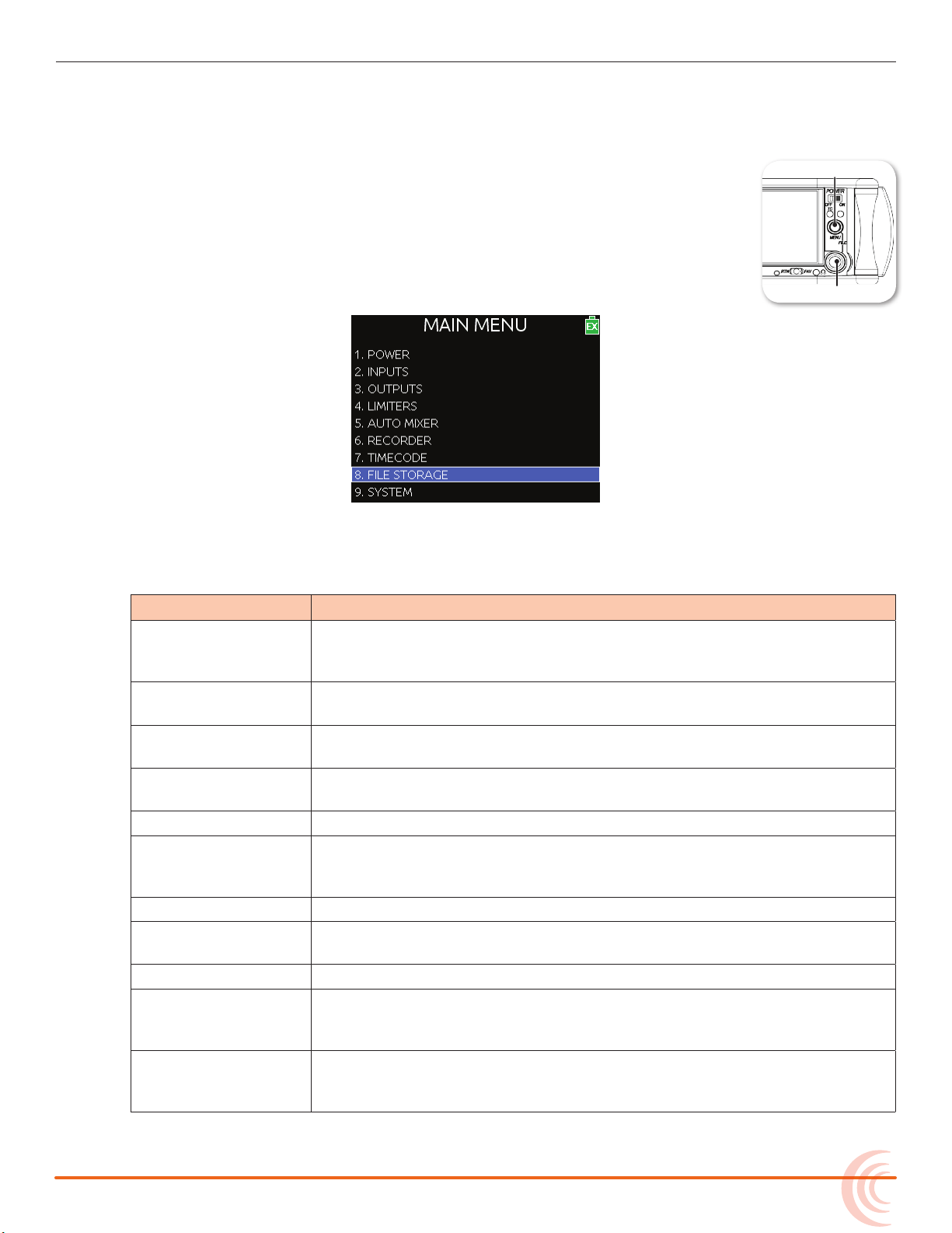
The majority of the 633’s settings are congured with the Main menu.
To access the Main menu:
X Press the MENU button.
The Main menu is made up of categories, each with its own set of
sub-menu options. Turn the Headphone encoder to navigate the
Main menu and press it in to select any category or sub-menu
option.
THE LCD AND USER INTERFACE
While sub-menu options are covered in more detail throughout this guide in
sections related to those options, the Main menu’s categories are provided with
brief descriptions in the following table.
category Description
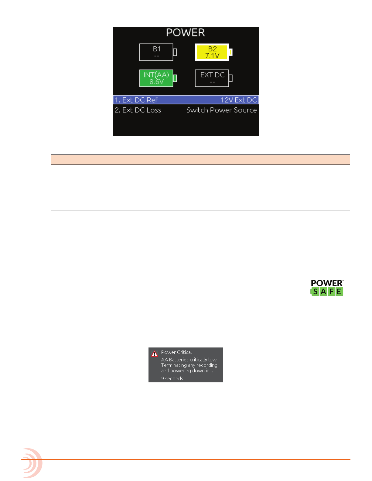
POWER Settings related to external power sources. Also displays voltage level of
External DC, Internal DC (AA), and Li-Ion batteries (labeled B1 and B2).
See Conguring Power Settings for details.
INPUTS Settings related to channel linking, phantom power, PFL modes, input to
ISO routing, and input delays. See Accessing Input Settings for details.
OUTPUTS Settings related to linking, output types or levels, output sources, output
routing, and output delays. See Accessing Output Settings for details.
AUTO MIXER Settings related to automatic mixing. See MixAssist & Dugan Automixing
for details.
LIMITERS Settings related to input and output limiters. See Limiters for details.
RECORDER Settings to target recording media, WAV sample rate / bit depth, MP3 bit
rate, and recording pre-roll time. See Accessing Recorder Settings for
details.
TIMECODE Settings related to timecode synchronization. See Timecode for details.
FILE STORAGE Settings related to le storage and metadata. See File Storage Settings
for details.
SYSTEM Various system settings. See System for details.
CL-12 Settings related to the CL-12 linear fader controller. This sub-menu is
disabled (grayed out) unless the CL-12 accessory is connected to the
mixer.
QUICK SETUP Allows user to save and recall user settings to and from SD, CF, and
internal memory. Also allows resetting all settings to factory default. See
Quick Setup for details.
17
Page 18

User Guide
Customizing the LCD and LEDs
Because the 633 is a portable eld mixer, it may be used in a variety of environments, including some where lighting is an issue that requires adjustments to
the mixer. With some System settings, you can modify the brightness levels of
the LCD, the brightness levels of the LEDs, and even enable or disable the LCD
Daylight mode.
To set the LCD brightness level:
1. Press the MENU button.
2. Turn and press the Headphone encoder to select SYSTEM > LCD Brightness.
3. Turn the Headphone encoder to change the value from 10 to 100%. Then
press the encoder to make your selection.
By default, the LCD brightness level is set to 100%.
To set the LED brightness level:
1. Press the MENU button.
2. Turn and press the Headphone encoder to select SYSTEM > LED Brightness.
3. Turn the Headphone encoder to change the value from 5 to 100%. Then
press the encoder to make your selection.
By default, the LED brightness level is set to 60%.
Using LCD Daylight Mode
The default appearance of the LCD screen is a dark theme—white text on black
background. However, a lighter theme—black text on white background—is
available as an alternative mode, which can make viewing in bright conditions
easier. When enabled, the LCD Daylight mode may be toggled between dark
and light themes.
To enable or disable LCD Daylight mode:
1. Press the MENU button.
2. Turn and press the Headphone encoder to select SYSTEM > LCD Daylight
Mode.
18
3. Do one of the following:
X Select On to enable.
X Select O to disable.
To toggle LCD Daylight mode:
X SELECT + HP: simultaneously press the SELECT and Headphone encoders.
Page 19
Headphone Monitoring
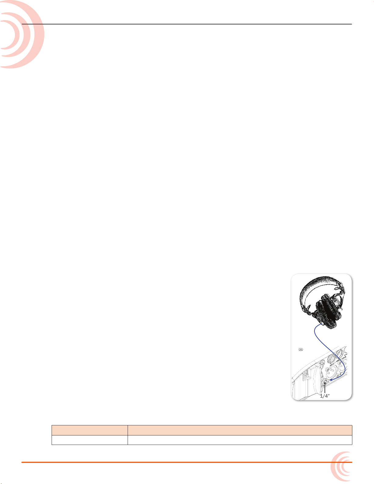
1/4”
The 633 provides a headphone output
on its right panel, several options for
headphone sources including up to 10
custom presets, plus a variety of other
customizable features related to audio
monitoring.
i An unbalanced 3.5 mm TRS connection
on the 633’s left panel, which is
primarily a multi-purpose auxiliary
analog output, may also be used for
headphones.
Connecting Headphones
Topics in this section include:
Connecting Headphones
Selecting Headphone Source
Setting Headphone Encoder Mode
Configuring the Headphone Preset List
Defining Custom Headphone Presets
Choosing a Favorite Headphone Preset
Using Headphone Source Shortcuts
Headphone Peak LED
Connect headphones to the 1/4-inch headphone output, located on the right
panel of the 633.
⚠ The 633 can drive headphones to dangerously high vol-
umes. Turn down the headphone gain before attaching
headphones or selecting a headphone source to prevent
accidental high levels. The range for headphone levels
may be set from OFF, -42 dB to +20 dB.
To adjust Headphone gain:
X Turn the Headphone encoder. The gain value will be dis-
played in the lower-right corner of the Main screen next to
the Headphone Source icon.
Selecting Headphone Source
The default list of headphone presets consists of six predened headphone
sources and 10 customizable presets. The predened headphone sources are:
Hp source Description
LR ST Master bus in stereo.
19
Page 20

User Guide
LR Mono Master bus summed mono to both ears.
L Mono Left channel of master bus sent to both ears.
R Mono Right channel of master bus sent to both ears.
LR MS ST Mid-side stereo - master bus decoded MS stereo to headphones. This
X1X2 Aux bus in stereo.
To select a headphone source:
1. Press the Headphone encoder to display the list of available sources.
2. Turn the encoder to change the headphone source. Options include: LR ST,
3. Press the encoder to close the list, or wait two seconds and it will close on
Hp source Description
is not to be used if the inputs are already linked as an MS pair.
LR Mono, L Mono, R Mono, LR MS ST, X1X2, and HP Preset (1) through HP
Preset (10).
The headphone source changes immediately as it is highlighted in the list.
its own. The chosen headphone source is displayed in the lower-right corner
of the Main screen next to the Headphone Source icon.
Setting Headphone Encoder Mode
The default functionality of the Headphone encoder can be reversed so that the
Headphone encoder must be pressed before turning to adjust the headphone
volume, and headphone source can be selected by simply turning the Headphone encoder.
To set Headphone Encoder mode:
1. Press the MENU button.
2. Turn and press the Headphone encoder to select SYSTEM > Headphone Encoder Mode > Preset/Vol. By default, this mode is set to Vol/Preset.
Configuring the Headphone Preset List
Presets can be excluded from this list to make preset selection simpler.
To edit the Headphone Preset list:
1. Press the MENU button.
20
2. Turn and press the Headphone encoder to select SYSTEM > Headphone Preset List.
The Headphone Preset List will be displayed; presets with a blue background are visible, and presets with a black background are hidden.
3. Turn and press the Headphone encoder to toggle visibility of each preset.
Page 21
HEADPHONE MONITORING
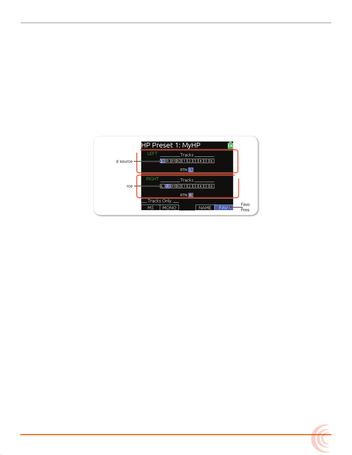
Assigned source
Favorite
Preset
Unassigned source
Right HP
Left HP
Defining Custom Headphone Presets
In addition to the six predened headphone sources, 10 options are available as
custom headphone presets.
To customize a headphone preset:
1. Press the Headphone encoder to display the list of available sources.
2. Turn the encoder to choose one of the 10 customizable preset options, such
as HP Preset(1).
3. Slide the MIC/TONE switch left or right.
The Headphone Preset Editing screen appears.
4. Turn the Headphone encoder to move the orange highlight to routing options.
5. Press the Headphone or Select encoder to change the selected source between O (black) and Assigned (blue).
i ISO sources will follow pre- or post-fade based on Input to ISO Routing settings.
6. (Optional) Do any of the following:
X Slide the MIC/TONE switch left to toggle MS decoding for this head-
phone preset.
X Slide the MIC/TONE switch right to toggle mono summing for this head-
phone preset (All active sources will be summed into both headphone
channels). This should not be used if inputs are already linked MS.
X Slide the RTN/FAV switch left to name the headphone preset.
X Slide the RTN/FAV switch right to toggle the favorite status of this head-
phone preset.
7. Press MENU or METERS to save the preset and exit the Headphone Preset
Editing screen.
i Only one preset at a time can be set as a favorite. Marking a preset as favorite will
remove the favorite status of all other presets.
21
Page 22
User Guide
Choosing a Favorite Headphone Preset
A single headphone preset can be designated as a favorite. This favorite
headphone preset can be quickly accessed via the front panel. The following
procedure assumes the Headphone Encoder Mode is set to Preset/Vol. For more
information, see Setting Headphone Encoder Mode.
To choose a predened Headphone preset as favorite:
1. Press the Headphone encoder to display the list of available sources.
2. Turn the Headphone encoder to highlight the predened preset you want.
Options include: LR ST, LR Mono, L Mono, R Mono, LR MS ST, and X1X2.
3. Slide the RTN/FAV switch right to set the highlighted Headphone preset as
your new favorite.
Using Headphone Source Shortcuts
There are two headphone monitor shortcuts on the 633: RTN and the headphone source set as favorite.
To monitor the favorite headphone source:
X Slide the RTN/FAV switch to the right.
To monitor RTN:
X Slide the RTN/FAV switch to the left.
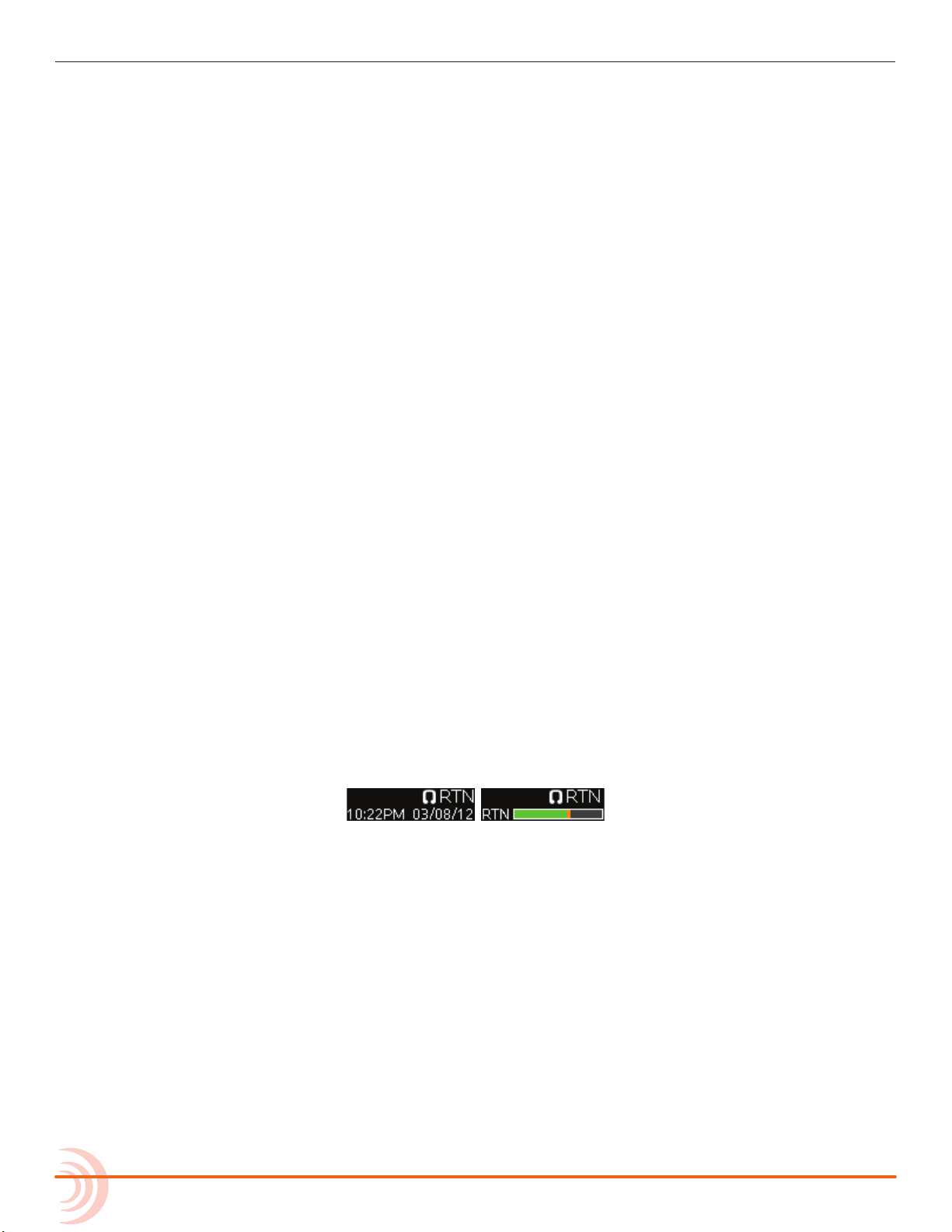
RTN will be be displayed in the lower-right corner of the Main screen next to the
Headphone Source icon. For meter views that do include a large RTN meter, the
date and time is displayed under For meter views that do not include a large
RTN meter, a smaller RTN meter is displayed under the Headphone Source icon.
Headphone Peak LED
The Headphone Peak LED, located just left of the Headphone encoder, illuminates red to indicate headphone output is approaching clipping level. Monitoring
without a visual indication of headphone clipping can mislead a sound mixer
into thinking the output or return feeds are distorted.
22
Page 23
Power
The 633 features a quad-powering
guration, which utilizes dierent
con
powering options, such as external DC
power, or it may be powered by six AA
batteries. Two rear mounts enable the
633 to be powered by Sony L-Series
batteries.
The 633 also incorporates exclusive
PowerSafe™ technology with smart
sensing of available power sources,
front panel power warning indication,
and an integrated 10-second power
reserve that safely stops recording and
shuts down in the event of a power loss.
Powering the 633
The 633 operates on either external DC power or battery power.
Topics in this section include:
Powering the 633
Using External Power
Using Battery Power
Voltage Ranges and Thresholds
Configuring Power Settings
PowerSafe
QuickBoot
Forcing Power Off (Optional)
Power Consumption
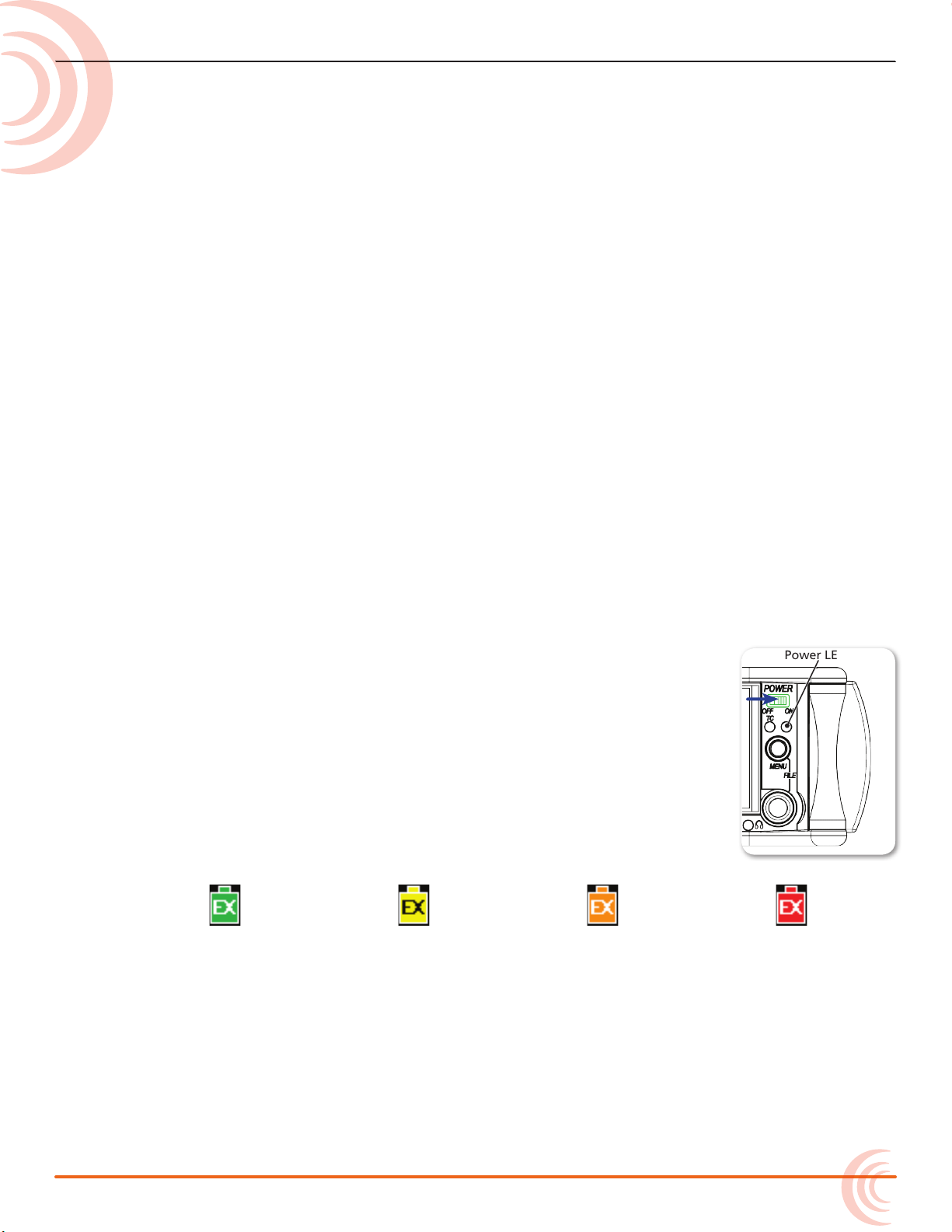
To turn on the 633:
X Flip the Power switch to the ON position.
The Power LED illuminates yellow then green. The Sound
Devices splash screen appears briey on the LCD, and then the
Main screen is displayed.
As part of the Main screen, the LCD displays a DC voltage indicator in the form of a battery icon that indicates the level and
type of the power source currently in use.
Normal Voltage
(Green)
Warning Voltage
(Yellow)
Low Voltage
(Orange)
Critical Voltage
(Red)
Using External Power
The 633 uses only one power source at a time, with external DC power taking
precedence over battery power. The order of precedence for power sources is:
Power LED
DC power (EX) > L-Series battery (B1) > L-Series battery (B2) > AA batteries (INT)
23
Page 24
User Guide
Following after these power sources is PowerSafe circuitry and its 10-second
power reserve, before shutdown.
To connect an external power source:
X Plug a DC power source (not included) into the 10-18 VDC input on the
right panel.
i Pin-4 of the locking, Hirose connector is positive (+) and pin-1 is negative (-).
Using Battery Power
The 633 uses up to two L-Series (Li-Ion) batteries and/or six AA batteries as a
backup to external power. Several power capacities are available in the L-Series
battery type, ranging from 1000 mAh to 7000 mAh. Larger amp-hour batteries
provide more run time. Alkaline AA batteries may be used with
the 633; however, NiMH (or 1.5V Lithium) batteries are the
preferred type because they provide for longer run times
compared to Alkaline batteries.
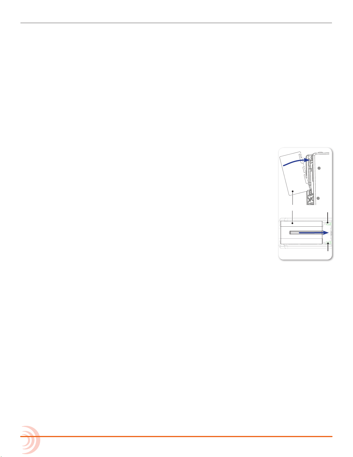
To mount L-Series batteries:
1. Place the 633 on a stable surface.
2. Position the battery so the two terminals on the battery line
up with the tips of the two pins on the rear panel of the 633.
3. Press the battery against the unit and slide the battery
onto the pins. The battery retainer clip will spring up with a
satisfying click to let you know the battery is secure.
To insert AA batteries:
1. Unscrew the battery cap (counter-clockwise).
2. Insert six AA NiMH batteries (not included) into the battery tubes. Orient
the batteries with the positive (+) end facing in and the negative (-) end
facing out.
i With external power connected, depleted AA batteries may be removed from the
633 and replaced with new ones without aecting operations.
Voltage Ranges and Thresholds
Li-Ion battery
Pin
Pin
24
The DC voltage indicator provides power status information based on the
External DC Reference parameter, which denes the voltage range and warning
threshold for external DC power sources. Setting the External DC Reference to a
value appropriate for the type of external power being used maximizes runtime
with that source.
For instance, the indicator appears solid green when the active power source is
Page 25
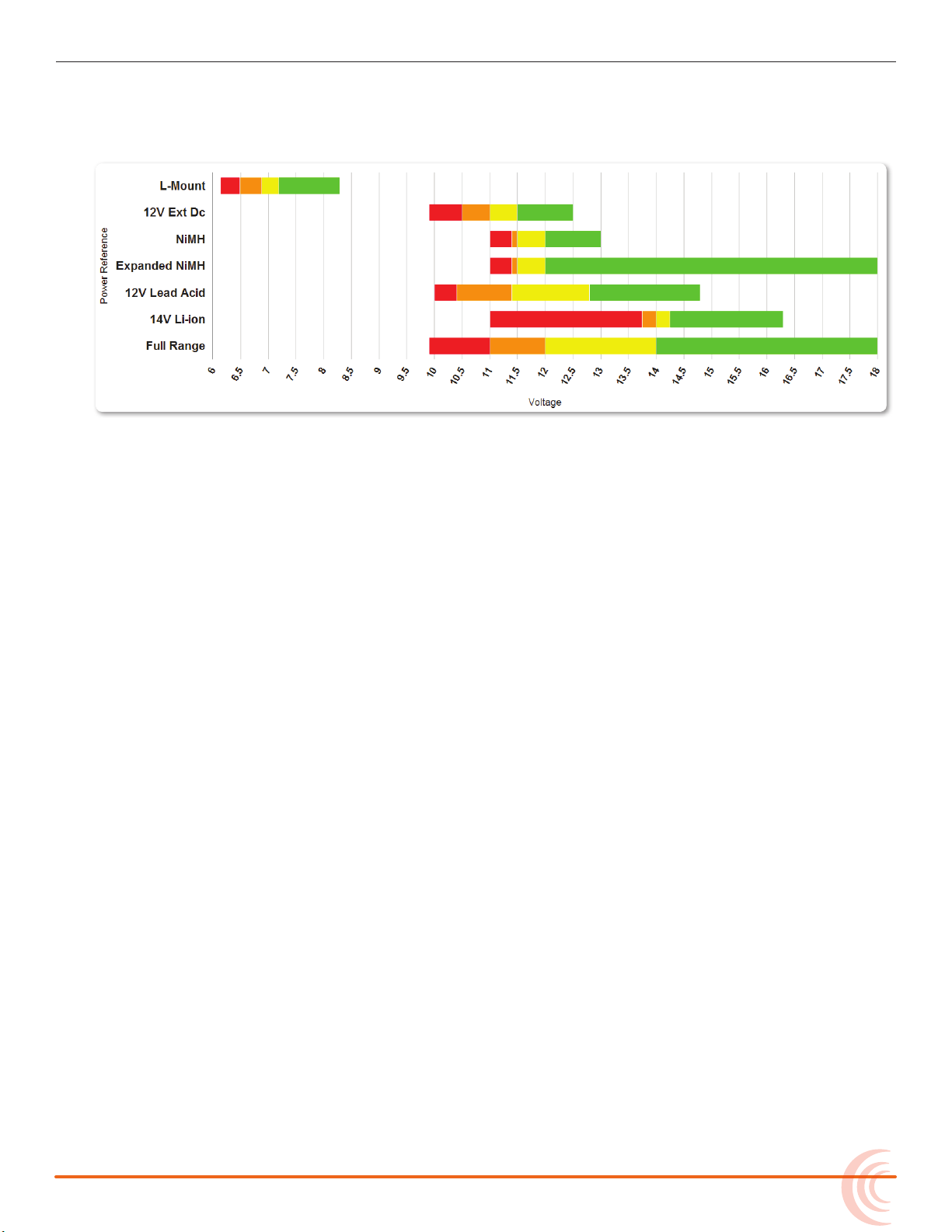
POWER
full or operating within the dened high voltage range. As the voltage depletes,
the indicator’s color changes from green to yellow (warning) to orange (low)
and to red (critical), based on the external power source’s range and threshold,
as shown in the following table:
If the active power source is removed or its voltage drops to the critical threshold, the 633 switches to alternative battery power or shuts down, according to
how its External DC Loss parameter is congured in the Power settings.
⚠ The DC voltage indicator ashes red when there are no other connected
backup power sources remaining with adequate voltage. When all power
sources are depleted, PowerSafe shutdown occurs automatically.
Configuring Power Settings
The 633 allows you to congure the type of external power source and what the
mixer should do in the event of an unintentional power loss.
To congure Power settings:
1. Press the MENU button.
2. Turn and press the Headphone encoder to select POWER.
The Power screen appears, from which numeric voltage levels of all connected power sources may be monitored. Disconnected power sources have
a black background and no voltage level. The power source currently in use
has a thick white border.
25
Page 26
User Guide
3. Adjust the settings based on the following table:
Ext DC Ref Calibrates the power level indicator accord-
Ext DC Loss Choose what action the 633 should take
parameter Description options
• 12V Ext DC
ing to the type of external DC source. By
default, this is set to 12V Ext DC.
Select the appropriate option for the
external DC power.
when external power is removed or voltage
drops below the set threshold. By default,
this is set to Switch Power Source.
i If the Ext DC Loss setting is congured to Switch Power Source when
external power is lost, but there are no internal batteries with adequate voltage in the 633, then automatic PowerSafe shutdown will
occur.
• NiMH
• Expanded NiMH
• 12V Lead Acid
• 14V Li-ion
• Full Range
• Switch Power
Source
• Shut down
PowerSafe
When all connected power sources are depleted or power is lost unexpectedly,
the PowerSafe™ circuitry activates. The 633 displays a warning, stops any active recordings, nishes writing les, and shuts down. The PowerSafe battery
powers the 633 during this time. This feature ensures that les are protected
even in the event of unexpected power loss.
i The PowerSafe battery recharges from the active power source only when the 633
is powered on.
26
Page 27
QuickBoot
QuickBoot™ circuitry is enabled for two hours after the 633 is powered down.
During this time, the 633 can turn on and start recording in less than two
seconds. Each time the 633 is turned on and o, the two-hour timer is reset.
Beyond the two-hour mark, QuickBoot is deactivated, so powering up results in
a normal, slightly longer boot-up process.
Within the two-hour time frame, while QuickBoot is enabled, the internal
Timecode (TC) generator continues to be active and the TC LED on the front
panel of the 633 blinks every two seconds.
Forcing Power Off (Optional)
In the unlikely event you need to manually force a complete shutdown of the
633, by-passing the PowerSafe and QuickBoot features, do the following:
To force power o:
POWER
1. Slide the Power button to the left.
2. Press and hold the MENU button for 5 seconds.
After the 633 is manually powered o, the QuickBoot is reset and the TC LED no
longer ashes.
i Manual shutdown will turn o the timecode backup battery, requiring timecode to
be rejammed and user bits to be reset upon next power up.
Power Consumption
Many factors inuence the rate at which the 633 uses battery power (current
draw). The following list highlights the larger current drawing functions.
• Microphone powering — The main source of extra 633 current draw. 48 V
Phantom can draw a large amount of current depending on what model
microphone is used. Two identical phantom powered microphones draw
twice as much current as one.
• Audio Recorder — The recorder, whether in record or playback, draws extra
current. Higher sample rate WAV recordings draw more current during recording.
• Digital Outputs — Disable digital outputs in the Main menu when they are
not needed since they draw additional current.
• Output level — Higher output levels into multiple, low-impedance inputs
increases current draw.
• Headphone Output circuit - High headphone output levels and low impedance headphones increase current draw.
• LED and LCD Brightness — Decrease LED and LCD brightness to reduce
current draw.
27
Page 28

User Guide
28
Page 29
Inputs
Fader (1-3)
Pan
PFL (Left: 1-3, Right: 4-6)
Trim
PFL status / Activity LED (4-6)
PFL status / Activity LED (1-3)
Mini-fader
(4-6)
The 633 has three full-featured audio
inputs on XLR-3F connectors, and three
additional line-level inputs on TA3
connectors.
Inputs may be used as either balanced
or unbalanced connections. There is no
change in gain between unbalanced and
balanced connections into the 633.
i For unbalanced connections, tie pin-3
to pin-1 of the XLR-3M connector of the
cable.
Physical Input Controls
Topics in this section include:
Physical Input Controls
Activating an Input
Accessing the Input Setting Screens
Setting Input Source
Setting Input High-Pass Filters
Setting L, R, X1, and X2 Routing
Using a Track Name Shortcut
Inverting the Phase
Adjusting Trim and Fader Controls
Adjusting Pan
Accessing Input Settings
Configuring Linking
Configuring Phantom Voltage
Configuring the PFL Toggle Mode
Configuring Input to ISO Routing
Configuring Input Delay
On the front panel, there are sets of controls related to inputs, such as pans,
faders, and trims.
The Trim, Pan, and Mini-fader controls may be pressed to retract the controls
into the front panel when not in use.
29
Page 30
User Guide
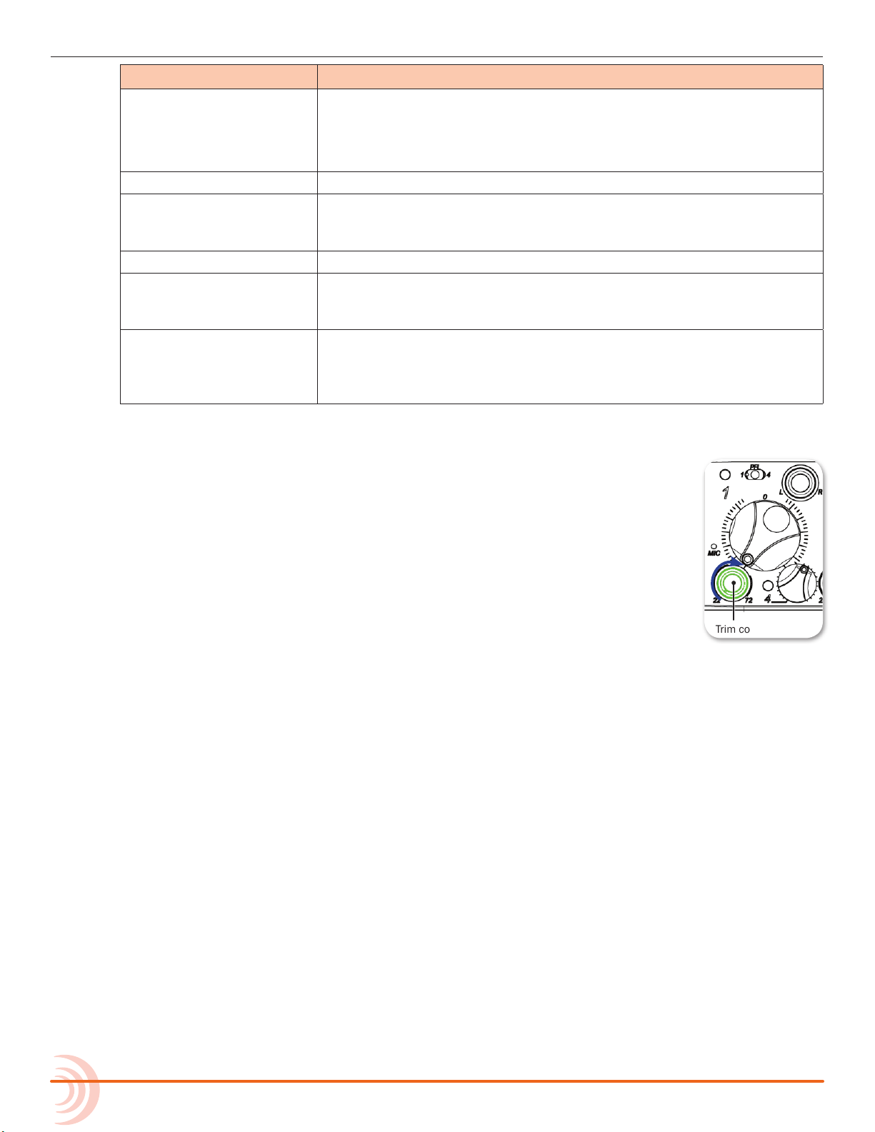
Trim control
control Description
PFL Pre-Fade Listen (PFL) switch. Solos input signal in headphone moni-
Fader 1-3 Adjusts fader level for inputs 1-3.
Trim 1-3 Activates inputs 1-3 and adjusts trim level for inputs 1-3. Trim level
Mini-fader 4-6 Activates inputs 4-6 and adjusts fader level for inputs 4-6.
Pan Controls the Left/Right balance of the input signal to the stereo
PFL Status / Activity LED • Green: Signal present on input (pre-fade).
Activating an Input
tor and displays Input Settings screen.
i PFL monitoring only aects the headphone monitor. It does not aect
audio sent to the outputs or internal recorder.
for inputs 4-6 are controlled from their respective Input Settings
screens.
master bus. Inputs 4-6 are routed to the L/R mix via their respective Input Settings screens.
• Red: Signal clipping on input (pre- and post-fade).
• Amber: Limiter engaged on input (pre- and post-fade).
• Blinking Yellow: Input soloed (PFL) in headphone monitors.
The 633 has three dedicated Trim controls on the front panel.
To activate inputs 1-3:
1. If the Trim control for an Input is recessed, push it in and it
will pop out.
2. Turn the Trim control clockwise until it clicks to activate the
input.
i The input is deactivated whenever the Trim control for that input is fully rotated
counter-clockwise.
To activate inputs 4-6:
1. If the Mini-fader control for an Input is recessed, push it in and it will pop
out.
2. Turn the Mini-fader control clockwise until it clicks to activate the input.
i The input is deactivated whenever the Mini-fader control for that input is fully ro-
tated counter-clockwise.
Accessing the Input Setting Screens
Each input has its own Input Settings screen. This screen provides access to the
input’s settings, such as input source, high-pass lter, and track routing, and
also displays information about the input’s gain and meter levels.
30
Page 31

INPUTS
Channel nameChannel number
L / R routing
Input source setting
Fader gain value
X1 / X2 routing
HPF setting
Trim gain value
Input level meter
Channel nameChannel number
L / R routing
Input source setting
Fader gain value
X1 / X2 routing
HPF setting
Input level meter
To access an Input Settings screen and PFL (solo) the input:
1. Ensure the chosen input has been activated.
2. Slide the PFL switch to the left for inputs 1-3 or right for inputs 4-6.
i Step 1 is based on factory defaults. If sliding the switch to the left does not
display the Input Settings screen, then the 633’s PFL Toggle Mode is not set to its
6-channel default. When the PFL Toggle Mode is set to only 3 channels, you must
slide the PFL switch to the right instead of the left since sliding to the left is used
to activate PFL without leaving the Main screen.
When the Input Settings screen is accessed, the headphone source is changed
to PFL for the chosen “solo” input. The headphone source returns to its previous
source after the Input Settings screen is exited.
i Hold the Select encoder down while sliding the PFL switch to access the Input
Settings screen without altering the headphone source. This behavior is reversed
when PFL Toggle Mode is set to 3 channels.
All Input Settings screens share some common elements, such as channel
name, channel number, level meter, trim and/or fader gain values, X1/X2
routing, HPF, and source selection.
Items displayed on the bottom half of the screen are adjusted by the physical
controls that they are near: Select encoder, MIC/TONE switch, RTN/FAV switch,
and Headphone encoder.
Input Settings screen for input 2 includes an INV option for inverting phase. For
31
Page 32

User Guide
more information on phase inversion, see Inverting the Phase.
Inputs 4-6 allow separate routing to L and R tracks, since these inputs do not
have pan controls.
Setting Input Source
Each input channel may be congured to receive signal from a unique source.
To set an input’s source:
1. Slide the PFL switch left to access the Input Settings screen for that input.
2. Press the Headphone encoder to display the list of available input sources.
Options include:
◦ OFF – Use to deactivate an input without having to change trim.
◦ MIC – Use for dynamic microphones or mic-level sources.
◦ MIC-PH – Use for microphones requiring phantom power.
◦ LINE – Use for analog line level sources.
◦ LINE-PH – Use for phantom-powered condenser microphones.
Provides 48V or 12V phantom power, but at a line-level gain
range. Useful in high sound-pressure-level environments.
◦ AES42 – Use for digital AES42 (Mode 1) microphones.
◦ AES3 – Use for a digital AES3 source.
3. Turn the Headphone encoder to select an input source.
Not all types of sources are available for each channel:
input types
Channel 1 OFF, MIC, MIC-PH, LINE, LINE PH, AES 42, AES 3
Channel 2 OFF, MIC, MIC-PH, LINE, LINE PH
i AES 42, AES 3 is conditionally available on Channel 2 only if Channel 1
is already set to AES 42 or AES 3
Channel 3 OFF, MIC, MIC-PH, LINE, LINE PH
Channel 4 OFF, LINE
Channel 5 OFF, LINE
Channel 6 OFF, LINE
4. Slide the PFL switch to the left again to return to the Main screen.
Headphone
Encoder
32
Page 33

Setting Input High-Pass Filters
Each input features a high-pass lter (HPF), which are useful for removing excess low frequency energy from audio signals, such as wind noise. For more
audio applications, engaging high-pass lter is benecial, because audio information below 100 Hz is rarely used, especially for speech reproduction.
The lter is o by default but may be adjusted from 80Hz to 240Hz in 10Hz increments.
To adjust an input’s high-pass lter:
1. Access the Input Settings screen for the input to be adjusted.
2. Push the Select encoder. The HPF label will become orange to indicate adjustment.
3. Turn the Select encoder to adjust the value.
4. Press the Select encoder (or wait 2 seconds) to exit adjustment mode. The
new value is saved, and the HPF label will become red again.
INPUTS
i When RECORDER > Sample Rate is set to 192k, the HPF options are o and 50
Hz.
The 633’s HPF circuit features an adjustable corner (-3 dB) frequency over a
range from 80 to 240 Hz. Below 80 Hz, the lter’s slope is 12 dB/octave. At
higher corner frequency settings, the slope is 6 dB/octave. The purpose for this
compound slope is to give additional roll-o at the 80 Hz setting to reduce wind
noise and low frequency rumble. The higher settings may be used to counteract
the proximity eect of directional microphones where a more gentle slope is
preferred.
The 633’s HPF circuit is unique because of its placement before any electronic
amplication. Most mixers’ HPF circuits are placed after the microphone
preamplier, such that all of the low-frequency signals get amplied. By virtue
of the 633’s circuit cutting the low-frequency signals before amplication, higher
headroom is achieved in the presence of signals with signicant low-frequency
energy.
When possible, attempt to equalize at the sound source with microphone
selection, placement, windscreens, and on-board microphone ltering. Many
microphones have on-board high-pass lters. Use the high-pass lters on the
633 in conjunction with the microphone’s lter to increase the lter’s slope.
Setting L, R, X1, and X2 Routing
Routing of inputs to L, R, X1, and X2 tracks can be adjusted quickly from the
Input Settings screen. An input’s routing to a track is indicated on the Input
Settings screen with labels in the bottom left (X1/X2) and bottom right (L/R) of
the LCD. A red label indicates the input is routed and a black label indicates the
input is not routed.
33
Page 34

User Guide
To route inputs 1-3 to L and R tracks:
1. Access the Input Settings screen.
2. Slide the RTN/FAV switch right to toggle L and R track routing together.
To route inputs 4-6 to L and R tracks:
1. Access the Input Settings screen.
2. Slide the RTN/FAV switch right to toggle track R routing, or left to toggle
To route any input to X1 and X2 tracks:
1. Access the Input Settings screen.
2. Slide the MIC/TONE switch right to toggle X2 routing, or left to toggle X1
i Independent assignment of signal to the L and R tracks for inputs 1-3 is adjusted
using the input’s dedicated Pan control.
track L routing.
routing.
i Slide the MIC/TONE switch right or left again for an additional routing (“PRE”),
which is available for X1 and X2 routes. This indicates a pre-fader routing.
Using a Track Name Shortcut
Track Names are stored in the metadata of each recorded le. The following list
displays the default track names:
Track L: MixL Track 1: Ch1 Track 4: Ch4
Track R: MixR Track 2: Ch2 Track 5: Ch5
Track X1: Aux1 Track 3: Ch3 Track 6: Ch6
Track X2: Aux2
An input’s track name can be quickly edited from the Input Settings screen.
To edit an input’s track name from the Input Settings screen:
1. Access the Input Settings screen for the input to be adjusted.
2. Hold the same switch (or shortcut) used to access the Input Settings screen
for 2 seconds. (For example, if the Input Settings screen was accessed by
sliding the PFL switch to the left, then hold the same PFL switch left for 2
seconds). The on-screen keyboard will appear allowing entry of a text value.
34
3. When nished, slide the RTN/FAV switch right (or Enter on attached USB
keyboard) to set the track name.
i Track names can also be edited from the Take List. For details, refer to Take List
Page 35

Overview.
1-3 Fader control
4-6 Mini-fader
1-3 Trim control
The way track names are displayed in meter views may vary, depending on a
system setting called Track Names in Meters. For more information, see Cong-
uring the Meters.
Inverting the Phase
Phase inversion is available only on input 2 of the 633. Phase inversion (or
polarity reversal) is used to compensate for incorrectly wired, balanced cables,
to prevent signal cancellation when a source is dual-mic’d from opposite
directions, or to reverse left/right with microphones in a mid-side (MS)
conguration.
To invert the phase of input 2:
1. Slide the PFL switch left to access the Input Settings screen for input 2.
2. Slide the RTN/FAV switch to the left. The INV label on screen will illuminate
red to indicate phase inversion.
INPUTS
Adjusting Trim and Fader Controls
The gain of an input is adjusted by two controls, Trim and Fader. This two-stage
architecture is identical to the topology of large mixing consoles and provides a
great deal of control. Trim is often thought of as a coarse gain control and the
Fader as the ne gain control.
The Fader is the primary control used while mixing, and it aects the level of
input signal routed to all post-fade destinations. Use the Fader control to make
ne gain adjustments. The Fader control can be attenuated from o (at full
counter-clockwise position) to +16dB above the set trim level (at full clockwise
position). Operate input faders at or near 0dB, the unity gain (12 o’clock) position to optimize gain structure for the best performance.
35
Page 36

User Guide
To adjust trim and fade:
1. Access the Input Settings screen for the chosen input.
2. Do one of the following:
3. Do one of the following:
X For inputs 1-3: Set Fader control to 0 dB, the unity gain position.
X For inputs 4-6: Set Mini-fader control to 0 dB. If the Mini-fader control
is recessed, push it in and it will pop out.
X For inputs 1-3: Adjust the input’s Trim control clockwise until optimal
level is achieved on metering and in headphones.
X For inputs 4-6: Access the Input Settings screen for the input chosen
from 4-6, and then rotate the SELECT encoder to adjust the trim level.
The gain value is displayed on the Input Settings screen.
For inputs 1-3 analog mic level is adjustable from +22 dB to +72 dB of
gain. Analog line level is adjustable from -30 dB to +16 dB, and AES digital
trim level is adjustable from -30 to +16 dB.
Adjusting Pan
The Pan pot routes inputs to the left (L) and right (R) channels of the stereo
Master Bus. The Pan pot has a detent in its center (12 o’clock) position.
To adjust an input’s pan (1-3):
X Turn the Pan pot.
After setting the pan, press the Pan pot in to recess the control when not in use.
i Inputs 4-6 are routed directly to L and R channels of the stereo Master Bus from
their respective Input Settings screens.
Accessing Input Settings
The Main menu has a sub-menu of settings related to inputs. These may be
used to customize the conguration of the 633.
To access Inputs sub-menu:
1. Press the MENU button.
36
2. Turn and press the Headphone encoder to select INPUTS.
sub-menu Description options
Ch 1-2 Linking Sets channel linking for input pair 1-2 • Unlinked
• 1-2
• 1-2MS
i M
S stands for Mid-Side.
Page 37

sub-menu Description options
Linked inputs have connecting background
Odd pan controls odd input (left) and even input (right)
Odd fader controls both inputs
Even trim controls even input
Odd fader and pan are disabled
Odd trim controls odd input
Ch 5-6 Linking Sets channel linking for input pair 5-6 • Unlinked
• 5-6
• 5-6MS
Phantom Voltage Globally adjusts voltage level of phantom
power (on all inputs which have phantom
power enabled).
PFL Toggle Mode Globally alters the behavior of PFL
switches.
Input to ISO Routing Sets pre- or post-fade status of each
input’s (1-6) routing to its ISO track.
Input Delays Sets delay for each input’s signal up to
30 ms in 0.1 ms increments.
• 48V
• 12V
• 6ch
• 3ch
• Prefade
• Postfade
• 0.0 - 30.0 ms
Configuring Linking
Pairs of adjacent inputs (1-2 and 5-6) may be linked as standard stereo pairs
or as a Mid-Side (MS) stereo pair. Linked inputs share a common fader. The pan
control of the odd input controls the balance of both signals to the L-R and X1X2 tracks. The following illustration indicates which controls are active and what
those controls do when inputs are linked.
INPUTS
To congure channel linking:
1. Press the MENU button.
2. Turn and press the Headphone encoder to select INPUTS, then the submenu option corresponding to the input pair: Ch 1-2 Linking or Ch 5-6
Linking
3. Turn and press the Headphone encoder to set linking, indicated by pairs.
Options include: Unlinked, Linked (pair), or Linked (pair) MS.
For instance, selecting 1-2 congures channel linking for input pair 1 and 2.
37
Page 38

User Guide
Mid-Side Linking
When input pairs are linked MS, the odd channel is used for the Mid signal and
the even channel is used for the Side signal. To produce a stereo signal from an
MS conguration, the signal from both microphones must be processed.
Mid-side matrixing is a method for processing audio signal from a cardioid
microphone and a bidirectional microphone into a stereo
signal. The cardioid microphone is the Mid signal and
connects to the odd input, and the bidirectional
microphone is the Side signal and connects to even
input. The cardioid microphone is pointed at the sound
source, and the bidirectional microphone is oriented
sideways—positioned with its capsule as near as
possible to the cardioid microphone’s capsule. The
diagram shows the relative polar patterns of
microphones in an MS conguration.
Selecting 5-6 MS, congures mid-side linking for input pair 5 and 6.
Mid Signal
Side Signal
Configuring Phantom Voltage
Phantom powering is a xed DC voltage of either 12 or 48 volts. This voltage is
resistively applied to pin 2 and pin 3 of an input’s XLR-3F connector, relative to
pin 1. In this conguration, there is no voltage dierence between signal pins 2
and 3.
On the 633, the factory default sets phantom power voltage to 48 volts, but
that may be changed.
To congure phantom voltage:
1. Press the MENU button.
2. Turn and press the Headphone encoder to select INPUTS > Phantom
Voltage.
3. Turn the Headphone encoder to change the setting. Options include: 48V or
12V.
This setting globally adjusts the voltage level of phantom power on all
inputs with phantom power enabled.
Configuring the PFL Toggle Mode
There are three PFL switches on the front panel of the 633. The rst applies to
inputs 1 and 4, the second to inputs 2 and 5, and the third is for inputs 3 and
6. By default, access to PFL and the Input Settings screen for inputs 1-6 can
be achieved with one hand. This is called 6-Channel mode. While in 6-Channel
mode, sliding a PFL switch either right or left will engage PFL on the chosen in-
38
Page 39

INPUTS
put and display its Input Settings screen. For instance, slide the rst PFL switch
left to view the Input Settings screen and activate solo PFL on input 1. Slide the
same switch right for input 4.
i The input’s PFL Status/Activity LED ashes yellow when PFL is engaged, and the
PFL number will appear in the lower right corner of the Input Settings screen (next
to a headphone icon).
However, the PFL switches on the 633 may be congured to focus operation
solely on inputs 1-3, while leaving inputs 4-6 accessible via a button combination. This conguration option is called 3-Channel mode.
To enable 3-Channel PFL Toggle mode:
1. Press the MENU button.
2. Turn and press the Headphone encoder to select INPUTS > PFL Toggle Mode
> 3ch.
i The INPUTS > PFL Toggle Mode submenu is disabled when the CL-12 linear fader
controller is connected to the mixer.
To engage solo PFL for inputs 1-3 while in 3-Channel mode:
X Slide PFL switch left.
To access inputs 1-3 Input Settings screens while in 3-Channel mode:
X Slide PFL switch right.
To engage solo PFL for inputs 4-6 while in 3-Channel mode:
X SELECT + PFL: press SELECT encoder and slide PFL switch left.
To access inputs 4-6 Input Settings screens while in 3-Channel mode:
X SELECT + PFL: press SELECT encoder and slide PFL switch right.
Configuring Input to ISO Routing
By default, each input is routed to its associated ISO track pre-fade (The fader
does not aect the signal on the ISO track). This routing can be congured (on
a per-input basis) to be post-fade (The fader does aect the signal on the ISO
track).
To congure Input ISO Routing:
1. Press the MENU button.
2. Turn and press the Headphone encoder to select INPUTS > Input to ISO
Routing.
3. Turn and press the Headphone encoder to select the desired input routing
39
Page 40

User Guide
and edit its value.
4. Turn and press the Headphone encoder to select Prefade or Postfade.
i Input to ISO Routing for inputs 1-6 also aects the pre- or post-fade status of
those inputs’ routing to AES digital outputs.
Configuring Input Delay
Input delay is applied before the signal is sent to the recorder and outputs.
Each input can be delayed up to 30ms.
To congure input delay:
1. Press the MENU button.
2. Turn and press the Headphone encoder to select INPUTS > Input Delays.
3. Turn and press the Headphone encoder to select the input. The background
of the value will become orange to indicate the value is being edited.
4. Turn and press the Headphone encoder to set the new delay value for the
chosen input.
40
Page 41

Outputs
Adjustment
Indicator
Outputs during gain adjustment
Link outputs
The 633 oers multiple outputs with
exible conguration. Whether you need
to send the LR mix to multiple cameras,
the camera RTN feed via IFB, or AES
digital signals, the 633 is up to the task.
The right panel features master LR
bus transformer balanced outputs
via two XLR-M connectors, which can
alternatively be used to send up to four
signals (two pairs) of AES digital, two
active balanced Aux outputs via TA3, an
additional unbalanced stereo Aux output
via a 3.5 mm unbalanced connector.
Output Connections
Topics in this section include:
Output Connections
Adjusting Output Gain
Accessing Output Settings
Configuring Output Linking
Setting Output Type and Nominal Level
Output Routing
Accessing AES Output Routing Screen
Accessing Aux (X1 - X4) Routing Screens
Configuring Playback to Outputs
Adjusting Output Delay
Sending Tone to Outputs
On the 633, the Left and Right XLR-M connectors are each transformer balanced
from separate windings. This improves isolation from potential interference.
The master outputs are capable of driving long cable runs. Aux outputs X1 and
X2 use active-balanced TA3 connections. The X3/X4 output (3.5mm TRS) and
Headphone output (1/4” TRS) are all unbalanced stereo connections.
i See Specications chapter for full details on the electronic specications of the var-
ious output connections.
Adjusting Output Gain
Output gain is adjusted from the Output meter view.
41
Page 42

User Guide
To adjust output gain:
1. Press the METERS button repeatedly until the Output meter view is visible.
i If the Output Meters view is not available, it must be selected as one of the three
views in main menu option SYSTEM > Meter Views.
2. Turn and press the SELECT encoder to choose an output and enter gain adjustment. The background color of the chosen output becomes orange, and
the output gain value is displayed in the lower-right corner of the screen.
3. Turn the SELECT encoder to adjust the output gain.
4. Press the SELECT encoder or wait two seconds to exit Gain Adjustment
mode.
i Output gain adjustments do not aect tone signal from the 633’s tone generator.
Accessing Output Settings
The Main menu has a sub-menu of settings related to outputs. These may be
used to customize the conguration of the 633 outputs.
To access Outputs sub-menu:
1. Press the MENU button.
2. Turn and press the Headphone encoder to select OUTPUTS.
sub-menu Description options
Linking Choose which output pairs are linked
for the purpose of arming and level
adjustment. By default, linking is set to
LR, X1, X2. Commas represent no
linkage, so LR, X1, X2 means L and R are
linked, while X1 and X2 are not.
XLR-L Out Select the nominal level of analog outputs
or switch the output to send AES digital
signals.
XLR-R Out Select the nominal level of analog outputs
or switch the output to send AES digital
signals.
TA3-X1 Out Select the nominal level of analog out-
put of the Aux 1 TA3 output. Line is the
default.
TA3-X2 Out Select the nominal level of analog out-
put of the Aux 2 TA3 output. Line is the
default.
AES Output Routing Displays the AES output routing matrix
where sources can be assigned to AES
output channels.
• LR, X1X2
• LR, X1, X2
• L, R, X1X2
• L, R, X1, X2
• Mic
• Line
• -10
• AES 1,2
• Mic
• Line
• -10
• AES 3,4
• Mic
• Line
• -10
• Mic
• Line
• -10
42
Page 43

sub-menu Description options
Playback to Outputs Select destination for playback signal. By
default, this is set to All Outputs.
X1, X2 Routing Displays the X1, X2 Routing screen where
sources may be assigned to the X1 and
x2 output channels.
X3, X4 Routing Displays the X3, X4 Routing screen where
sources may be assigned to the X3 and
x4 output channels.
Output Delays Set independently the delay of L-R, X1,
X2, X3 and X4. Default for each is 0.0.
Configuring Output Linking
Output linking allows the gain, delay, and track arm status (L, R, X1 and X2
only) of an output pair to be controlled with only one action.
To congure output linking:
OUTPUTS
• All Outputs
• Headphones Only
• 0.0 - 10.0 frames
(per output)
1. Press the MENU button.
2. Turn and press the Headphone encoder to select OUTPUTS > Linking.
3. Turn and press the Headphone encoder to select a linking option. Options
include: LR, X1X2 (both pairs linked); LR, X1, X2 (only L and R linked);
L, R, X1X2 (only Aux 1 and 2 linked); and L, R, X1, X2 (none linked)
Setting Output Type and Nominal Level
By default, left and right XLR balanced outputs are set to analog Line (+4 dBu
nominal) level. However, each output—both left and right XLRs and both TA3
outputs for X1 and X2—may be set to Mic, Line, and -10 (analog). Additionally,
left XLR and right XLR may be set to AES (digital).
To set output level and type:
1. Press the MENU button.
2. Turn and press the Headphone encoder to select an OUTPUTS submenu,
which include: XLR-L Out, XLR-R Out, TA3-X1 Out, and TA3-X2 Out.
3. Turn and press the Headphone encoder to select the output type. Options
for each output will vary, but can include: Mic, Line, -10 or AES.
43
Page 44

User Guide
Routed source
Unrouted source
Highlight
Output Routing
The master L and R tracks are permanently routed to their respective outputs,
unless the connections have been set to AES, in which case they use AES output routing.
Accessing AES Output Routing Screen
There is a total of 4 channels of digital output on 2 connections. Each of the
XLR-3M outputs can be congured to output AES3 digital signals. For more information, see Setting Output Type and Nominal Level.
Any track can be routed to any AES output in any combination. No sources are
assigned to any of the AES outputs by default.
To access the AES Output Routing screen:
1. Press the MENU button.
2. Turn and press the Headphone encoder to select OUTPUTS > AES Output
Routing.
Configuring AES Output Sources
The AES Output Routing screen consists of rows that represent each AES output
and columns that represent the available source for those outputs.
To congure output sources in the AES Output Routing screen:
1. Do one of the following:
X Turn the Headphone encoder to move the orange highlight horizontally.
X Turn the Select encoder to move the orange highlight vertically.
44
2. Press the Headphone or Select encoder to change the selected source between O (black) and On (blue).
i ISO tracks are routed to AES outputs pre- or post-fade depending on the Input to
ISO Routing setting. For more information, see Conguring Input to ISO Routing.
Page 45

Accessing Aux (X1 - X4) Routing Screens
Post-fade routing
Pre-fade routing
Highlight
Post-fade routing
Highlight
Aux 1 and Aux 2 analog signal output is provided on a pair of balanced TA3 connections. Aux 3 and Aux 4 analog signal output is provided on a single, unbalanced, 3.5 mm TRS connection.
ISO tracks or L and R tracks may be routed individually to X1, X2, X3, and X4.
ISO tracks may be routed pre- or post-fade. L and R tracks can only be routed
post-fade.
Additionally, headphone L and R signal may also be routed to X3 and X4, a
feature useful for sending a copy of the monitor signal to a boom operator or
other production members. Changing the headphone source will change the
copied signal routed to X3 and/or X4.
i RTN signal cannot be routed to X3 and X4. When headphone signal is routed to
X3 or X4, and RTN signal is routed to the headphone preset, RTN signal will be
present in the headphone output, but not in X3 or X4.
Output sources are congured separately in either the X1, X2 Routing or X3, X4
Routing screens.
OUTPUTS
To access either of the Aux (X1-X4) Routing screens:
1. Press the MENU button.
2. Do one of the following:
X Turn and press the Headphone encoder to select OUTPUTS > X1, X2
Routing.
X Turn and press the Headphone encoder to select OUTPUTS > X3, X4
Routing.
45
Page 46

User Guide
Locked
Unlocked
Configuring Aux Output Sources
The Aux (X1-X4) Routing screens consist of boxes that indicate sources available for routing to the chosen output.
The X1, X2 Output Routing screen diers from the X3, X4 Routing screen. For
instance, Aux and HP sources are not available, but an additional Input Setting
option does appear on the X1,X2 Routing screen:
When Input Setting is set to Locked, changing the X1 and X2 routing from the
Input Settings screens is disabled, preventing accidental routing of channels to
those outputs using the MIC/TONE switch.
To congure output sources via the Aux (X1-X4) Routing screens:
1. Access either the X1, X2 Routing or X3, X4 Routing screens.
2. Do one of the following:
X Turn the Headphone encoder to move the orange highlight horizontally.
X Turn the Select encoder to move the orange highlight vertically.
3. Press either encoder to change the selected source between O (black) and
On (blue). Selecting All ISO Tracks, available on either screen, globally applies pre- or post-fade status to all ISO track routings to the Aux outputs.
i In addition to O and On, ISO sources have a third option, Pre-Fade (green).
For X1 and X2, activating an ISO source will turn o any L or R source, and vice
versa. For X3 and X4, activating HP sources will turn o all LR, Aux, and ISO
sources, and vice versa.
46
Page 47

Configuring Playback to Outputs
Delay value during adjustment
By default, audio on L and R recorded tracks will be sent to the headphone outputs and both L and R outputs during playback. This can be disabled so that LR
analog outputs do not send the playback signal to the L and R outputs.
To congure playback to outputs:
1. Press the MENU button.
2. Turn and press the Headphone encoder to select OUTPUTS > Playback to
Outputs.
3. Turn and press the Headphone encoder to select either Headphones Only or
All Outputs.
Adjusting Output Delay
The signal of each output can be delayed by up to 10.0 frames. This is useful
while interfacing with video equipment when the audio signal is being processed
faster than video, creating an audio/video oset.
OUTPUTS
To adjust output delay:
1. Press the MENU button.
2. Turn and press the Headphone encoder to select OUTPUTS > Output Delays.
3. Turn and press the Headphone encoder to enter delay adjustment mode.
The background of the selected delay becomes orange.
4. Turn the Headphone encoder to adjust the delay value by 0.1 frame
increments, from 0.0 (no delay) up to a maximum of 10.0 frames.
5. Press the Headphone encoder to set the delay value.
47
Page 48

User Guide
Sending Tone to Outputs
The 633’s internal tone oscillator can be used to send a predened tone or pulse
to the mixer’s outputs to aid setup of proper gain staging with other equipment,
such as cameras. The Left Indent pulsing tone is useful for identifying the left or
odd Aux channel of the stereo pair on the receiving device.
To send a continuous tone to outputs:
X Do one of the following:
◦ Slide the MIC/TONE switch to the right for a brief burst of tone.
◦ Slide and hold the MIC/TONE switch for one second to turn on a continu-
ous tone. Slide the switch again to turn o the tone.
By default, 1000 Hz tone is sent at 0 dB to all outputs and tracks.
To send an L Ident pulsing tone:
X Press and hold the SELECT encoder then slide the MIC/TONE switch to the
right.
By default, a continuous tone is sent to outputs while the Left Identier signal
pulses the amplitude of tone by -20 dB to the Left channel, X1 and X3 outputs.
Repeat the SELECT + TONE combination to turn o the L Ident pulse.
These factory defaults may be customized via System settings. Custom conguration includes: routing to outputs or tracks, setting decibel level and frequency,
and changing the functionality of the MIC/TONE switch actions.
For details, see Setting up Tones and Bells.
48
Page 49

MixAssist & Dugan Automixing
Input not assigned to
Auto Mixer
Mode Selection
Input assigned to
Auto Mixer
The 633’s digital processing engine
delivers 6-channel auto-mixing
capability using the most sophisticated
algorithms on the market.
Commonly used in multi-mic speech
applications, auto-mixing automatically
attenuates the level of inputs that are
not open and helps maintain consistent
background sound levels regardless of
the number of open microphones.
On the 633, sound professionals have
two powerful Auto Mixers from which
to choose: MixAssist™ and Dan Dugan
automixing. These are two avors,
which accomplish the same end—
improved speech intelligibility, reduction
of ambient noise and reverberation, and
improved gain-before-feedback.
Auto Mixer Screen
Topics in this section include:
Auto Mixer Screen
Turning the Auto Mixer On or Off
Assigning Inputs to the Auto Mixer
Overview of MixAssist
Setting MixAssist Off-Attenuation
LCD Views During MixAssist Automixing
Overview of Dugan Automixing
LCD Views During Dugan Automixing
While the 633 is capable of auto-mixing all 6 inputs, it may be congured from
the Auto Mixer screen to attenuate fewer inputs or none at all.
The 633 also features two auto mixers: Sound Devices own automixing feature
called MixAssist and Dan Dugan automixing.
To access the Auto Mixer screen:
1. Press the MENU button.
2. Turn and press the Headphone encoder to select AUTO MIXER. The Auto
Mixer screen is displayed.
49
Page 50

User Guide
Input not assigned to MixAssist
MixAssist is On
Input assigned to MixAssist
Variable Off-Attention Setting
Input not assigned to Dugan
Dugan AutoMix is On
Input assigned to Dugan
Turning the Auto Mixer On or Off
By default, auto-mixing is turned o, but it may be turned on and any of the 6
inputs can be assigned to the Auto Mixer. See also Assigning Inputs to the Auto
Mixer for more information.
To turn on automatic mixing:
1. Access the Auto Mixer screen.
2. Press the Headphone encoder to activate Mode selection.
3. Turn and press encoder again to select a mode to use from one of two options: MixAssist, Dugan AutoMix.
i Auto Mixer, in either mode, is disabled automatically when Main menu option RE-
CORDER > Sample Rate is set to a value higher than 48.048 kHz.
The Auto Mixer screen varies, depending on what mode is chosen.
To turn o automatic mixing for all inputs:
50
Both Auto Mixer modes are designed for use with multi-mic speech
applications and are not intended for musical applications. For more
information about each mode, see Overview of MixAssist and Overview of
Dugan Automixing.
X From the Auto Mixer screen, select O in the Mode section.
Page 51

MIXASSIST & DUGAN AUTOMIXING
Assigning Inputs to the Auto Mixer
Inputs that are assigned to an Auto Mixer (MixAssist or Dugan) are referred to
as active automixed inputs and will be included in the mix. Inputs not assigned
to the Auto Mixer are referred to as inactive automixed inputs and will not be
included in the mix.
To assign inputs to MixAssist or Dugan AutoMix:
1. Access the Auto Mixer screen.
2. Turn the Select encoder to move the orange highlight vertically down to the
Input Selection section.
3. Turn the Headphone encoder to move the orange highlight horizontally.
4. With the orange highlight positioned on the selected source, press either
encoder to change the selected input to either Not Assigned (black) or
Assigned (blue).
i Inputs that are routed post-fader to the L or R bus and do not have Auto Mixer
activated will not be auto-mixed but will still be analyzed by MixAssist for the
purposes of Last Mic Lock-On, One Mic Per Sound Source, and Number of Open
Mics Attenuation.
Overview of MixAssist
The Sound Devices MixAssist feature auto-mixes post-fade input signals to the
left (L) and right (R) buses. Other signals are not aected by MixAssist.
MixAssist does not limit the number of open microphones and will allow several
microphones to be open simultaneously if there are several talkers. MixAssist
also intelligently attenuates redundant mics that are picking up the same sound
source, which signicantly helps to reduce comb ltering and phasing artifacts.
Inputs that are automixed will be open (unattenuated) when a person talks into
the input’s microphone and closed (attenuated) when the person stops talking.
Microphone channels open with ultra-sensitive responsiveness to voice levels to
ensure that no syllables are lost, and then will “gate o” smoothly over 500mS.
This gating action is smooth and imperceptible when switching between microphones. MixAssist is more sophisticated than a simple gate, and uses four different principles to automix input signals: noise adaptive threshold, one mic per
sound source, number of open mic attenuation, and last mic lock-on.
51
Page 52

User Guide
Noise Adaptive Threshold
When an input’s post-fade level surpasses the MixAssist threshold, it will be
opened. Unlike a simple limiter or gate, this threshold is dynamic: MixAssist
continuously analyzes all inputs assigned to it to determine an average noise
oor level and uses that level as the threshold. This prevents common background noise (fans, crowd murmur, etc.) from causing the input to open, while
allowing normal sounds to open the mic.
One Mic Per Sound Source
Often a sound source, such as someone speaking, is captured by more than
one microphone. MixAssist actively compares signals from all inputs and when
it senses the same audio on multiple inputs, it will only open the input in which
that specic program audio arrived rst and is loudest.
i This does not prevent another input from opening when unique program audio is
sensed at that input.
Number of Open Microphone Attenuation
As the number of open inputs increases, the level of each input as it is routed to
the track will decrease by 3 dB per doubling of open mics. This ensures that the
overall level of the track is consistent regardless of the amount of open inputs
routed to it.
Last Mic Lock-On
When talking stops, the last input to be active will remain open. This maintains
a consistent level of natural sound and avoids a dramatic transition to silence on
the track, even when no inputs are in use.
Setting MixAssist Off-Attenuation
The 633 also lets the user dene the amount of o-attenuation that MixAssist
uses during the auto-mixing process.
To set the amount of o-attenuation for MixAssist:
52
1. From the Auto Mixer screen, with MixAssist set as the Mode, use the Select
encoder to move the orange highlight vertically down to the MixAssist OAttenuation eld.
2. Press the Headphone encoder to select the eld; its background will appear
orange.
Page 53

MIXASSIST & DUGAN AUTOMIXING
Closed input
Open input
3. Turn the Headphone encoder to change the setting. Range is from 6 dB to
40 dB in 1 dB increments.
LCD Views During MixAssist Automixing
A circle icon is displayed next to the meter for each active automixed input.
When the input is open, the circle will be green. As the input closes, the circle
will fade to black.
The Meters view displays these circle icons to the right of (horizontal meters)
the active automixed inputs.
The Input Settings screen will display the circle icon to the right of the meter.
53
Page 54

User Guide
Panned Right
Panned Left
Overview of Dugan Automixing
In collaboration with Dan Dugan Sound Design, Inc., Sound Devices oers
another powerful automixing option as part of the 688’s Auto Mixer. The Dugan
Speech System™ uses Dugan’s own patented automixing algorithm that has
been an industry standard for many decades.
Dugan’s system operates on a very elegant principle: each individual input
channel is attenuated by an amount (in dB) equal to the dierence (in dB)
between that channel’s level and the sum of all channel levels. The gain of
all channels is adjusted immediately and continuously based on what each
channel is receiving. The neat aspect of this mathematical construct is that the
total gain through the system never changes—always stays at 0dB. The core
concept of this mixer is totally automatic, so there are no thresholds or other
adjustments to set.
With Dugan automixing, multi-mic speech applications are mixed with smooth
automatic cross-fades for clear, optimized audio recordings.
LCD Views During Dugan Automixing
A circle icon is displayed next to the meter for each active automixed input. The
amount of purple lling the circles indicates the level of automix attenuation. If
the input is panned left or right, a purple half circles appears accordingly.
attenuation
No
Full attenuation
The Meters view displays these circle icons to the right of (horizontal meters)
the active mixed inputs.
54
The Input Settings screen will display the circle icon to the right of the meter.
Page 55

MIXASSIST & DUGAN AUTOMIXING
55
Page 56

User Guide
56
Page 57

Limiters
Limiters prevent clipping by attenuating
signals that exceed a set threshold. The
amount of attenuation is dened by the
ratio of the limiter and expressed as two
numbers.
The time it takes for limiting to begin
once signal has exceeded the threshold
is referred to as the attack time, and
the time it takes for limiting to cease
once signal has fallen back below the
threshold is referred to as release time.
Overview
Topics in this section include:
Overview
Enabling the Limiters
Adjusting the Threshold
Linking Limiters
Sound Devices recommends using limiters at all times. Without input limiters,
high signal conditions can overload a channel and cause distortion. In normal
operation, with a properly set gain structure, the threshold of the input limiter is
rarely reached. The default threshold of all limiters on the 633 is 16dBu.
All 633 limiters use a 20:1 compression ratio. This means that any signal that
exceeds the threshold by 20 dB will exit the limiting stage at only 1 dB above
the threshold. The 633 limiters have a 1 ms attack time and a 500 ms release
time.
The input limiter is actively limiting when the respective input’s Input Activity
LED illuminates yellow. Limiting activity will also be displayed as a yellow square
on the right side of the input’s meter on the Main screen. If the limiting activity
is regularly indicated, reduce the amount of gain applied to the channel by turning down the Trim control.
57
Page 58

User Guide
Enabling the Limiters
When enabled, the limiters are globally activated at either a Hard Knee or Soft
Knee setting. The knee of the limiter determines how the limiter operates in
relation to the set threshold. With hard knee, when the signal reaches the
threshold, the mixer immediately attenuates only those peaks above the
threshold, compressing at whatever ratio is set. With soft knee, attenuation
begins slightly before the threshold—at about 6 dB—for a more gradual, tapelike sound, making the compression much more dicult to detect.
To enable or disable limiters:
1. Press the MENU button.
2. Turn and press the Headphone encoder to select LIMITERS > Limiter
Enable.
3. Turn and press the Headphone encoder to activate or deactivate the limiter.
Options include: O, Hard Knee, and Soft Knee.
Adjusting the Threshold
The default threshold of all limiters is 16 dBu; however, that may be adjusted
from 4 dBu to 18 dBu in 1 dBu increments.
To adjust the threshold:
1. Press the MENU button.
2. Turn and press the Headphone encoder to select LIMITERS.
3. Dene the threshold parameters based on the following table:
parameter Description options
Input 1-6 PostFade Threshold
L, R Threshold Sets the limiter threshold for the Master Bus. • +4 dBu - +18 dBu
X1, X2 Threshold Sets the limiter threshold for the Aux Bus. • +4 dBu - +18 dBu
Sets the level at which input limiters will begin
attenuating on inputs 1-6.
Linking Limiters
• +4 dBu - +18 dBu
(1 dBu increments)
(1 dBu increments)
(1 dBu increments)
58
Limiters for L, R and X1, X2 channel pairs can be linked on the 633. Anytime
two limiters are linked, both channels will be limited when signal reaches the
threshold in any channel of the pair.
i Linking inputs as a stereo pair also links those inputs’ limiters.
Page 59

LIMITERS
To link limiters:
1. Press the MENU button.
2. Do either one or both of the following:
X Turn and press the Headphone encoder to select LIMITERS > L, R Link-
ing.
X Turn and press the Headphone encoder to select LIMITERS > X1, X2
Linking.
3. Turn and press the Headphone encoder to set linking. Options include: On
or O.
59
Page 60

User Guide
60
Page 61

Recording
Media Door
The 633 oers 10-track, polyphonic
or monophonic broadcast WAV le
recording—or two tracks of compressed
MP3 audio—to Secure Digital (SD)
and CompactFlash® (CF) cards. These
memory cards are an easy-to-source,
reliable, and aordable le storage
option that also may be quickly
delivered to post immediately after
recording stops.
All common sampling rates are
supported, including up to six tracks at
192 kHz.
The memory cards can be set
independently, recording either identical
material for real-time backup, or
combinations of WAV Poly, WAV Mono
and MP3 les.
Using Media
Topics in this section include:
Using Media
Using the Transport Control
Arming or Disarming Recording Tracks
Accessing Recorder Settings
Setting File Type and Media Track
Assignment
Changing the MP3 Bit Rate
Setting the Sample Rate
F Sample Modes
Setting the Bit Depth
Setting the Pre-roll
Using the Slate Microphone
Playing Back Active Takes
Viewing Approved Media List via Smart
Phone
Before recording anything, install and format the media storage memory cards
you intend to use in the 633. The slots for memory cards are located on the
right panel behind the Media Door, which is held closed magnetically.
To insert media:
1. Firmly pull open the Media Door.
2. Insert your choice of media memory card into the slots
provided.
When inserting the SD card, ensure the bottom of the card
(the side with metal contacts visible) is facing the rear of
the unit. When inserting a CF card, ensure the top of the
card (the side with the branding label) is facing the rear of
the unit.
i Sound Devices Quality Assurance engineers have done extensive
testing to ensure media approved for use with the 633 works reliably and provides the best performance in a variety of extreme
conditions. When choosing your media, please refer to the Approved Media List available on the Sound Devices website at:
www.SoundDevices.com/ApprovedMedia. For more information,
see also Viewing Approved Media List via Smart Phone.
CF Memory
Card Slot
SD Memory
Card Slot
61
Page 62

User Guide
METERS
Button
Headphone
Encoder
MENU
Button
Transport
Control
The memory card must be formatted before recording.
To (re)format an SD or CF card:
1. Press the MENU button.
2. Turn and press the Headphone encoder to select File Stor-
3. Do either of the following:
4. Press the Headphone encoder to begin the formatting process.
5. Read any warning message(s) and press the Headphone encoder to contin-
6. Press the METERS button to return to the Main screen.
⚠ Reformatting a card will erase all data on the card.
age.
◦ Select Erase/Format CF to reformat a Compact Flash
card.
◦ Select Erase/Format SD to reformat a Secure Digital
card.
ue.
Using the Transport Control
The 5-position Transport control is used to perform all recording and playback
functions.
Function Direction action
Record
Pause / Stop
Play
Push up the Transport control.
Begins recording a new le.
Press in the Transport control.
While recording, press once to stop recording.
While in playback, press once to pause, and
press again to stop. While in standby, press
and hold to display next take name.
Push down the Transport control.
Begins playback of the last le recorded or le
currently loaded.
Push the Transport control left.
62
Rewind / Load previous take
Fast forward / Load next take
While in standby, push left to load the previous
take. While in playback, push and hold left to
rewind.
Push the Transport control right.
While in standby, push right to load the next
take. While in playback, push and hold right to
fast forward.
Page 63

RECORDING
Take name during recording
Timecode during recording
Yellow text indicates media is being written to
L and R tracks (Armed)
Armed ISO track
Unarmed ISO track
Powered off input
To make a recording:
1. Push up the Transport control. Recording will begin.
While recording, both the take name background color (top of Main screen)
and timecode counter (bottom left of Main screen) will become red, and the
absolute time counter (bottom of Main screen) will run. Additionally, the
time remaining value of CF and SD will appear yellow while the media is
being accessed.
2. Press in the Transport control to stop recording.
i Some transport controls, such as start/stop record and arming tracks may be done
from the Wingman app. For more details, see Wingman Integration: 6-Series.
Arming or Disarming Recording Tracks
The 633 features 10 recording tracks. Each of the six inputs is permanently
routed to its associated ISO track. Buses L, R, X1, and X2 can also be armed for
recording.
ISOs can be sent to both pre- and post- fade. X1 and X2 can record any combination of channels pre- or post-fade.
To arm or disarm a track for recording:
1. Press the METERS button repeatedly until the chosen track is visible on the
Main screen.
2. Turn the SELECT encoder to move the white highlight to the chosen track.
63
Page 64

User Guide
3. METERS + SELECT: Press the METERS button and SELECT encoder together.
The background color changes to indicate the track’s armed status.
Red = armed, Grey = unarmed, and Black = input powered o.
Accessing Recorder Settings
The Main menu has a sub-menu of settings related to recording. These may be
used to customize the conguration of the 633’s Record settings.
To access the Recorder sub-menu:
1. Press the MENU button
2. Turn and press the Headphone encoder to select RECORDER.
sub-menu Description options
Record to CF Sets the type of le and which tracks to
record to the CF card.
The default is Wav Poly.
Record to SD Sets the type of le and which tracks to
record to the SD card.
The default is Wav Poly.
i When a CL-12 is in use and both media are set to Wav Mono, the following message will appear
when the REC button is pressed to begin recording.
“When CL-12 is in use, it is highly recommended to record monophonic les to only one card. Set
one card to polyphonic and the other to monophonic.”
MP3 Bit Rate The bit rate of recorded MP3 les.
The default is 320kbs.
Sample Rate The internal sample rate and sample rate
of recorded WAV les.
The default is 48k.
Bit Depth The bit depth of recorded WAV les.
The default is 24.
• O
• Wav Poly
• Wav Poly (ISOs Only)
• Wav Poly (LR Only)
• Wav Poly (X1X2 only)
• MP3 (LR)
• MP3 (X1X2)
• Wav Mono
• Wav Mono (ISOs only)
• O
• Wav Poly
• Wav Poly (ISOs Only)
• Wav Poly (LR Only)
• Wav Poly (X1X2 only)
• MP3 (LR)
• MP3 (X1X2)
• Wav Mono
• Wav Mono (ISOs only)
• 320kbs
• 192kbs
• 128kbs
• 44.1k
• 47.952k
• 47.952kF
• 48k
• 48.048k
• 48.048kF
• 88.2k
• 96k
• 192k
• 24
• 16
64
Page 65

sub-menu Description options
Pre-roll Time Adjust the amount of record time to be
appended before each recording. Maximum
value is 3 seconds when recording WAV
Mono les to any media.
Higher sample rates also limit pre-roll.
Rates of 88.2 and 96k should be 3 seconds, and 192 kHz is 1 second.
The default is 0 seconds.
Setting File Type and Media Track Assignment
The 633 supports simultaneous recording to CF and SD media. By default, all
armed tracks are recorded to both cards as a polyphonic WAV le. It is possible
to record only the armed ISO tracks, only the armed L and R tracks, or only the
armed X1 and X2 tracks to either media.
To set le type and track routing:
RECORDING
• 0 - 6 seconds (1s increment)
1. Press the MENU button.
2. Turn and press the Headphone encoder to select either of the following:
◦ RECORDER > Record to CF
◦ RECORDER > Record to SD
3. Turn and press the Headphone encoder to choose a le type and track assignment for the chosen media. For more information on available options,
see Accessing Recorder Settings.
WAV (Broadcast WAV)
The 633 writes AES-31 broadcast WAV formatted les. The audio les created
by the 633 include additional metadata in the le’s header, Broadcast Audio
Extension (BEXT) and iXML data chunks. Software that does not recognize these
additional broadcast WAV data chunks will ignore them. For more information,
see Metadata Overview.
MP3
MPEG-1 Layer III is a lossy compression algorithm, often used for music and
transcription recording purposes. The 633 records two-channel MP3 audio les
with data rates of 128, 192, and 320 kbs. For more information, see Changing
the MP3 Bit Rate.
i MP3 recording is only possible when RECORDER > Sample Rate is set to 44.1k or
48k.
65
Page 66

User Guide
Changing the MP3 Bit Rate
The 633 records MP3 les at a default bit rate of 320kbs, but that bit rate may
be changed. A high bit rate MP3 le preserves more audio information with an
increased le size. A low bit rate MP3 le preserves less audio information with
a decreased le size.
To change the MP3 bit rate:
1. Press the MENU button.
2. Turn and press the Headphone encoder to select RECORDER > MP3 Bit
Rate.
3. Turn and press the Headphone encoder to select a bit rate. Options include:
128, 192, and 320 kbs.
Setting the Sample Rate
The 633 records WAV les at 48 kHz sample rate by default.
To set sample rate:
1. Press the MENU button.
2. Turn and press the Headphone encoder to select RECORDER > Sample Rate.
3. Turn and press the Headphone encoder to select a sample rate. Options include: 44.1k, 47.952k, 47.952kF, 48k, 48.048k, 48.048kF, 88.2k, 96k, and
192k.
The sample rate value is stored in le metadata. Those options with “F” are
F mode rates. The F stands for “faux” or “Fostex”.
Certain restrictions apply when using sample rates at or greater than 88.2 kHz:
88.2 - 96 kHz 192 kHz
Maximum record tracks 8 6
WAV mono recording Warning Message displayed: Sample rate limit for Wav Mono
recording exceeded. Reduce sample rate or set to Wav Poly.
Maximum pre-roll time 3 seconds 1
High-pass lters Unchanged O or 50 Hz
X3/X4 outputs Available Available
AES outputs Available Disabled
Limiters Available Disabled
Input delay Available Disabled
Output delay Available Disabled
66
Page 67

F Sample Modes
The 48.048kF mode is used in specic work ows with Avid®, Final Cut Pro®,
and other post-production environments that do not recognize audio les written at 48.048 kHz. In this mode les are recorded at a 48.048 kHz sampling
rate but are stamped at 48 kHz. When played, they will play back 0.1% slower
than real time.
One use for the 48.048kF mode is to force a 0.1% speed reduction (pull down)
of audio to match MOS-telecined lm (24 fps-to-NTSC) in non-linear edit systems, such as Avid or Final Cut Pro. Since the le is stamped as a 48 kHz le,
the edit system will play it back at 48 kHz and not at 48.048 kHz. This “audio
pull down” will match the transferred picture without the need for an intermediate step through other software to create the pull down.
When using 48.048kF sample rate, set main menu option TIMECODE > Frame
Rate to 30ND or 24. When set to 30ND, les will be stamped with a frame rate
of 29.97. When set to 24, les will be stamped with a frame rate of 23.97ND.
Both 47.952 and 47.952kF settings use a record sampling rate of 47.952 kHz,
0.1% lower than 48 kHz. The 47.952kF mode, however, identies the le as
being recorded at 48 kHz.
RECORDING
When using 47.952kF sample rate, set main menu option TIMECODE > Frame
Rate to 23.97ND or 29.97ND. When set to 23.97ND, les will be stamped with a
frame rate of 24. When set to 29.97ND, les will be stamped with a frame rate
of 30ND.
i MP3 recording is not allowed in “F mode”.
Setting the Bit Depth
The 633 records 24 bit WAV les by default. Bit depth denes the digital word
length used to represent a given sample and correlates to the maximum dynamic range that is represented by the digital signal. Larger bit depths accommodate a wide dynamic range.
To set bit depth:
1. Press the MENU button.
2. Turn and press the Headphone encoder to select RECORDER > Bit Depth.
3. Turn and press the Headphone encoder to select 24 or 16.
i The bit depth value is stored in le metadata.
67
Page 68

User Guide
Setting the Pre-roll
Pre-roll buering is available on the 633 to help prevent missing record cues or
up-cutting takes. By default, the pre-roll time is 0 seconds (o). When active,
pre-roll begins recording at a set number of seconds preceding the record button being pressed.
To set pre-roll time:
1. Press the MENU button.
2. Turn and press the Headphone encoder to select RECORDER > Pre-roll
Time.
3. Turn and press the Headphone encoder to select a value (0 s to 6 s).
i While a pre-roll time may be set regardless of the timecode mode, pre-roll is
ignored whenever timecode mode is set to Record Run. Additionally, when the
mixer’s timecode mode is set to either External Timecode Auto Record, or External
Timecode Continuous Auto Record, pre-roll is only applied within the Hold O
period and never before receiving rolling timecode value from the master external
timecode source. This prevents possible overlapping timecode numbers between
adjacent les. For more information, see Setting the Timecode Mode and Setting
Timecode Hold O.
i Maximum pre-roll time is 3 seconds when RECORDER > Sample Rate is set to
88.2k or 96k.
Maximum pre-roll time is 1 second when RECORDER > Sample Rate is set to
192k.
Using the Slate Microphone
The 633’s built-in slate and external microphone is used to notate scenes from
the mixer location. Its audio performance is not suitable for critical recording
applications. It should be used for documenting scenes and for communication
purposes only.
To use the slate microphone:
1. Slide the MIC/TONE switch left to activate the slate mic. The Slate/Tone LED
illuminates green to indicate the slate mic is active.
2. Slide the MIC/TONE switch left again to deactivate the slate mic.
i By default, the slate mic is routed to all tracks and outputs. The gain of the slate
mic can be adjusted. For details, see Setting Slate Mic Gain.
68
Page 69

Playing Back Active Takes
Active take Current playback card
Playback may be initiated at any time except when the 633 is recording. Unless
playback is initiated from the Take List or File List, the active take will be played
from the current playback card. The active take is whichever take was recorded or played most recently. The active take is displayed at the top of the Main
screen.
RECORDING
To play back the active take:
X Push the Transport control down in any view beside the File List or Take List.
X To play back a specic le from the Take List or File List, push the Transport
control down while a le is highlighted in one of those views. For details,
see Take List Overview and Accessing the File List.
To toggle playback to a dierent media card:
X HP + Play: Press and hold the Headphone encoder, then push the Transport
control downward (Play).
Viewing Approved Media List via Smart Phone
The 633 provides QR codes on screen for smart phone access to product-related
documentation, including the Approved Media List, available online.
i Accessing documentation via a QR code requires the installation on your smart
phone of a code reader application—many of which are available as free downloads
from App stores.
To access the Approved Media List via QR code:
1. Press the MENU button.
2. Turn and press the Headphone encoder to select RECORDER > Approved
Media List.
3. Using your phone’s code reader application, scan the QR code to access the
Approved Media List, which is a web page on the Sound Devices website.
69
Page 70

User Guide
70
Page 71

Slate Mic and Return
The 633 is equipped with one stereo
return (RTN) which allows the Sound
Mixer to hear camera audio directly
from the 633 interface to ensure quality
audio is being sent to camera.
The 633 can also utilize its built-in slate
mic for an “all call” (Slate) to any of its
outputs or record tracks.
Disabling the Slate Microphone
Topics in this section include:
Disabling the Slate Microphone
Setting Slate Mic Gain
Routing the Slate Mic
Using the Slate for Notation
RTN Monitoring
The slate microphone can be used to audibly identify a scene or slate at
the start of recording or communicate one-way with other members of the
production crew. The 633 incorporates a built-in slate mic, located near the left
edge of the mixer’s front panel.
The slate mic’s audio performance is not suitable for critical recording
applications; it should be used for documenting scenes and for communication
purposes only.
The slate microphone is enabled, by default, but may be turned o.
To disable the slate microphone:
1. Press the MENU button.
2. Turn and press the Headphone encoder to select SYSTEM > Slate Mic.
3. Turn and press the Headphone encoder to select O. This disables the left
slide action of the MIC/TONE switch.
i Repeat the procedure, selecting On, to re-enable the built-in slate mic.
71
Page 72

User Guide
Setting Slate Mic Gain
The gain of the slate microphone is 36 dB by default. If this gain is too high, it
can be adjusted:
To adjust slate microphone gain:
1. Press the MENU button.
2. Turn and press the Headphone encoder to select SYSTEM > Slate Mic Gain.
3. Turn the Headphone encoder to adjust slate mic gain (0 dB - 36 dB).
i For quick adjustment of slate microphone gain, slide the MIC/TONE switch to the
left and hold while turning the Headphone encoder.
Routing the Slate Mic
By default, the slate microphone is routed to all outputs and tracks. This routing
may be customized.
To route the slate microphone:
1. Press the MENU button.
2. Turn and press the Headphone encoder to select SYSTEM > Slate & Tone
Routing. The Slate and Tone Routing screen is displayed.
3. Do one of the following:
X Turn the Headphone encoder to move the orange highlight horizontally.
X Turn the Select encoder to move the orange highlight vertically.
4. Press either encoder to change the selected source between O (black) and
On (blue).
72
Page 73

Using the Slate for Notation
To activate the slate function momentarily:
1. Slide and hold the MIC/TONE switch left. The slate mic activates, the Slate/
Tone LED illuminates green, and the headphone monitor source changes to
SLATE when slate is active.
2. Release the MIC/TONE switch. The slate mic deactivates, the Slate/Tone
LED turns o, and the headphone monitor reverts to its previous source.
To lock the slate function on:
1. Slide the MIC/TONE switch left. The slate mic activates, the Slate/Tone LED
illuminates green, and the headphone monitor source changes to SLATE.
2. Slide the MIC/TONE switch left again. The slate mic deactivates, the Slate/
Tone LED turns o, and the headphone monitor reverts to its previous
source.
SLATE MIC AND RETURN
RTN Monitoring
Return audio, fed to the 633 via the RTN input on the mixer’s right panel, can
be quickly monitored on the headphone output with a toggle of the RTN/FAV
switch.
When monitoring return audio, RTN metering is displayed as either part of the
meter view (as shown in far right image) or as a smaller RTN meter located in
the bottom right corner of the screen (as shown in the other two predened
meter views). When displayed as part of the meter view, the smaller RTN meter
is replaced with the date and time.
To adjust the RTN level:
1. Press the METERS button to toggle to a meter view that displays RTN
metering.
2. Turn and press Select encoder to choose the RTN meter. The RTN meter
label will change to orange to indicate Level Adjustment mode.
73
Page 74

User Guide
3. Turn the Select encoder to adjust the RTN level, which can be adjusted in
4. Press the Select encoder again to exit Level Adjustment mode. Otherwise,
1 dB increments from 0 dB down to -30 dB. During adjustment, the value is
displayed in the lower right corner of the screen.
Level Adjustment mode will end if the encoder is not turned for 2 seconds.
74
Page 75

Timecode
Timecode
Frame rate or sample rate
The 633 features a fully-integrated
Ambient™ timecode generator and
reader that supports all common rates
and modes. The 633 holds accurate
timecode for up to two hours after
shutdown, using its own internal,
Lithium-Ion timecode battery. This
timecode battery is charged whenever
the 633 is powered on.
i After two hours without power, the 633
reverts to a slightly less-precise time-
of-day crystal to maintain the date and
time on the device.
Timecode
Topics in this section include:
Timecode
Setting the Timecode Mode
Setting the Frame Rate
Setting Timecode Hold Off
Jamming the Timecode
Setting the Timecode Generator
Setting User Bits
Setting Display Mode
File-based recorders place a timecode and frame rate stamp in the BEXT and
iXML chunks of an AES31 Broadcast WAV le. During playback, the mixer generates SMPTE timecode from this number and extrapolates it based on the
timecode frame rate. All les generated by the mixer have timecode numbers
that begin on the 0 frame (or 02 in DF modes) and end on the 0 frame such
that a le’s duration is always an integer number of seconds long. If necessary,
pre-roll and post-roll is dynamically applied to accomplish this, simplifying synchronization in post-production. The timecode value and frame rate of the 633
are displayed on the Main screen.
i If sample rate is displayed–as shown–instead of the frame rate, toggle the view to
frame rate by holding METERS down and slide the RTN/FAV switch to the left.
75
Page 76

User Guide
Setting the Timecode Mode
The Timecode mode determines if the mixer generates or reads timecode from
an external source, and when timecode runs and stops.
To set the Timecode mode:
1. Press the MENU button.
2. Turn and press the Headphone encoder to select TIMECODE > Timecode
Mode.
3. Select a mode. Options include:
options moDe type Description
O N/A Turns timecode mode o.
Rec Run Generator Timecode runs while recording and is stationary
Free Run Generator Timecode runs continuously. Timecode continues
Free Run Auto Mute Generator Timecode runs continuously; however, timecode out-
Free Run Jam Once Generator Allows the mixer to automatically jam to an external
24h Run Generator Timecode runs continuously with its value based on
24h Run Auto Mute Generator Timecode runs continuously with its value based on
Ext-TC Reader Timecode is derived from external timecode sources.
Ext-TC Auto-Rec Reader Timecode is based on external timecode sources,
Ext-TC/Cont Reader/
Generator
when not recording. In this mode, timecode
defaults to the last stationary value at power-up.
When switching to Record Run from another mode,
the internal generator will stop at the last timecode
value.
counting for up to two hours after power-down.
put is muted during standby. This is useful for triggering external devices when in free run timecode
workows.
valid timecode source when rst connected. Once
jammed, the mixer will retain the timecode count
even when disconnected from external source and
for up to two hours after the mixer is powered down.
the mixer’s time and date settings. This is useful for
workows requiring timecode be referenced to the
Actual Time clock.
mixer’s time and date settings; however, timecode
output is muted during standby.
and allows recording on the mixer to be triggered
via external timecode starting and stopping.
Timecode is based on external timecode sources.
If timecode is disconnected, the mixer continues
counting from the same value, using its internal
timecode generator. This is useful when working with
wireless timecode sources, allowing the mixer to
free-wheel through wireless dropouts.
76
Page 77

options moDe type Description
Ext-TC Auto-Rec/Cont Reader/
Generator
Timecode is based on external timecode sources,
and allows recording on the mixer to be triggered
via external timecode starting and stopping. Also,
if timecode is disconnected, the mixer continues
counting from the same value, using its internal
timecode generator. This is useful when working with
wireless timecode sources, allowing the mixer to
free-wheel through wireless dropouts. In the event
of a dropout, the mixer will stop recording when it
receives a stationary value.
Setting the Frame Rate
By default, the 633’s frame rate for the timecode generator is set to 30nd.
i The frame rate value is stored in the Frame Rate eld of metadata.
When using an external timecode mode, ensure the mixer’s frame rate is equal
to (or cross-jam compatible to) the external frame rate.
TIMECODE
To set frame rate for the timecode generator:
1. Press the MENU button.
2. Turn and press the Headphone encoder to select TIMECODE > Frame Rate.
Options include: 23.98, 24, 25, 29.97nd, 29.97df, 30nd and 30df.
Setting Timecode Hold Off
Some devices that send Rec-Run timecode will have a tendency to occasionally
send short bursts of running or invalid timecode. When using these devices as
an external timecode to trigger recording, this behavior can result in unintentional recordings or invalid timecode stamps on the mixer. To prevent this, the
633 features a Timecode Hold O function.
This feature only applies when in Ext-TC Auto-Rec and Ext-TC Auto-Rec/Cont
timecode modes.
When using these external timecode auto-record modes, the 633 will delay the
start of recording for a specied “hold” time. Running timecode that lasts for
less than the Hold O value will not trigger a recording on the 633.
To set up Timecode Hold O:
1. Press the MENU button.
2. Turn and press the Headphone encoder to select TIMECODE > Hold O.
3. Specify the hold time in 0.1 second intervals. Options include: 0.0 s - 8.0 s.
i If a pre-roll time is set, it will be applied. Pre-roll will only capture audio from the
initial detection of a timecode signal. If no pre-roll is selected, the le will begin after the Hold O period expires. It is best practice to set pre-roll to a value greater
77
Page 78

User Guide
than the specied Hold O value. This ensures that audio is captured from the moment a timecode signal is detected and that unintentional les triggered by short
bursts of timecode are not generated.
Jamming the Timecode
The Jam Received TC screen (better known as the Timecode Jam menu)
displays detailed information about the mixer’s internal SMPTE timecode
generator and external SMPTE timecode received via the mixer’s timecode
input. It also shows any dierence between the two and features a button
allowing you to jam the timecode if necessary.
If the mixer’s time and date are reset during the production day, or if the
Timecode mode is changed from 24h Run to another mode and back, the
timecode value will change. To ensure proper synchronization, you must re-jam
all timecode devices.
To access the Timecode Jam menu, do one of the following:
X Press METERS + MIC.
X Press MENU, and then use the Headphone encoder to select TIMECODE >
Jam Menu.
To manually jam the timecode:
X From the Timecode Jam menu, press the Headphone encoder.
To exit the Timecode Jam menu without jamming:
X Press either the MENU or METERS button.
Setting the Timecode Generator
78
Timecode values may also be manually set.
To set the timecode generator:
1. Press the MENU button.
2. Turn and press the Headphone encoder to select TIMECODE > Set
Generator TC.
Page 79

The Set Generator TC screen appears with four elds representing hours
(HH), minutes (MM), seconds (SS), and frames (FF).
3. Navigate the screen’s elds by doing the following:
X Turn the encoder to move orange highlight from one eld to the next.
X Press the encoder to select a eld. Chosen elds appear blue.
4. Turn and press the encoder to change each eld’s value.
5. When nished with your edits, turn the encoder to highlight Done and press
the encoder to save your new timecode value.
Setting User Bits
By default, you may customize the user bits with a four-eld format, delineated
by colons, such as UU:UU:UU:UU, where U represented a user-denable value.
TIMECODE
Often, the rst three elds in the format are manually reset daily using twodigit numerical values for the date, such as MM:DD:YY:UU or DD:MM:YY:UU.
The User Bits mode lets you congure the device to automatically populate the
rst three elds with values derived from the system’s date.
A fourth mode allows user bits to be derived from an external source. If that
mode is to be used, ensure the external source for timecode user bits is
attached to the 633 via the 5-pin LEMO connector on the mixer’s right panel
before setting the mode.
To set User Bits mode:
1. Press the MENU button.
2. Turn and press the Headphone encoder to select TIMECODE > Set
Generator UBits.
3. Press the encoder again to select one of four mode options:
◦ UU:UU:UU:UU — four, two-digit, user-denable elds (the default)
◦ MM:DD:YY:UU — rst three two-digit elds represent month, day, year
◦ DD:MM:YY:UU — rst three two-digit elds represent day, month, year
◦ Use External — After the values are received from the external source, it
may be disconnected from the mixer. The 633 will retain those values for
up to two hours after power down.
i When set to MM:DD:YY:UU or DD:MM:YY:UU, the system will populate the rst
79
Page 80

User Guide
Timecode
Absolute Time
three elds, so those elds will appear grayed out in the Set Generator UB screen,
leaving only the last eld (UU) to be customized by the user. When set to Use External, the elds appear grayed out and the eld labels change from UU to XX.
Setting Display Mode
By default, the timecode is displayed as the largest clock on the screen in meter
views. However, you may reverse the positioning of the timecode and absolute
time clocks on all meter views so that the one you deem most important is large r.
To reverse the clock display:
1. Press the MENU button.
2. Turn and press the Headphone encoder to select TIMECODE > Display
Mode. Options include:
options Description
Big A-time Displays absolute time as the larger clock in all Meter Views.
Big Timecode Displays the timecode as the larger clock in all Meter Views.
80
Page 81

File Storage
scene number
take number
extension
S01T01.WAV
scene number
take number
track designator
extension
S01T01_3.WAV
The 633 has multiple options for le
management of the SD and CF cards.
In this section of the guide, we discuss
the le and folder structure, copying
les from one media to another,
transferring les from the CF or SD card
to a computer, formatting media and
generating CSV Sound Reports directly
from the 633 interface.
File Structure
Topics in this section include:
File Structure
Transferring Files to PC
Take List and File List
Accessing the File List
Deleting Files or Folders
File Storage Settings
Setting Folder Options
Generating Sound Reports
Changing the Take Designator
Defining File Max Size
Setting Scene Increment Mode
Setting Take Reset Mode
Setting File Playback Mode
Selecting a Default Playback Card
Erasing / Formatting Media
The 633 records polyphonic or monophonic audio les. Polyphonic recordings
have multiple audio tracks within a single le. Monophonic recordings have a le
for each audio track.
Polyphonic le names consist of a scene name, take number, and a le exten-
sion:
Monophonic le names consist of a scene name, take number, mono track designator, and a le extension:
The track designators are associated with the 633 tracks. This diers from track
names which may be edited and are covered in depth in the Metadata section of
this guide. For more details, see Editing Metadata on the 633.
81
Page 82

User Guide
This table illustrates the association between 633 tracks, track names, and track
designators.
track track name track Designator
Track L MixL 1
Track R MixR 2
Track 1 Ch1 3
Track 2 Ch2 4
Track 3 Ch3 5
Track 4 Ch4 6
Track 5 Ch5 7
Track 6 Ch6 8
Track X1 Aux1 F
Track X2 Aux2 G
Transferring Files to PC
When nished recording, and the media remaining time on the Main screen is
white, you may remove the SD or CF card(s) from the 633 and mount them to
any computer to transfer your recorded les using a card reader or card slot.
To remove the SD card:
1. Open the Media Door.
2. Push it in to release the card, and then pull it out.
To remove the CF card:
X Open the Media Door and pull out the card.
To transfer les:
1. Mount your memory card to your computer.
2. Copy the les from the card to the computer.
i Sound Devices recommends that you copy les rst before editing les on the
computer. Do not edit les directly from the memory cards.
Take List and File List
A le is an individual le stored on attached media. A take is a single recording
that can consist of multiple les on one or both media. The Take List displays a
list of takes and provides functions for deleting, renaming, and editing information in metadata elds. Edits made in the Take List will be applied to both SD
and CF cards, if applicable. For details on the Take List, see Take List Overview.
82
Page 83

FILE STORAGE
File list of CF root File list within a folder (named “Dune”)
Accessing the File List
The File List displays les and folders on a chosen media and provides functions
for deleting les or folders, copying les or folders to other media, renaming
folders, creating sound reports, formatting media, and emptying Trash and
False Take folders. The File List functions only apply to the chosen media.
To access the File List:
1. Press the MENU button.
2. Turn and press the Headphone encoder to select FILE STORAGE > File List.
i An alternative way to access the File List is by sliding the MIC/TONE switch while
the Take List screen is displayed. That switch acts as a toggle between the File List
and Take List screens.
The rst screen displays each media and general information along with
menu options.
3. Slide the RTN/FAV switch to access options for the card. Options include:
◦ Create Sound Report
◦ Copy to other card
◦ Rename
◦ Empty Trash
◦ Erase/Format
If necessary, to return to the Card screen, press MENU.
4. Turn and press the Headphone encoder to select CF or SD and view its contents. A list of les on that card will be displayed. Folder names are preceded by a slash (“\”).
83
Page 84

User Guide
5. Turn the Headphone encoder to highlight a chosen le or folder. Information
pertaining to your selection appears on the right.
6. Slide the RTN/FAV switch to access options. The OPTION menu will vary depending on the le or folder selected.
Folder options include:
◦ Create Sound Report
◦ Empty Folder (Trash and False Takes folders only)
◦ Copy Directory to other card
◦ Rename folder
◦ Delete folder from chosen card
File options include:
◦ Copy le to the other card
◦ Delete le from chosen media
Deleting Files or Folders
Files and folders may be deleted from the File List.
i File deletion applies only to the chosen media. To delete all les associated with a
take, use the Take List.
To delete a le or folder:
1. From the File List, turn and press the Headphone encoder to select CF or
SD. A list of les on that card will be displayed.
2. Turn the Headphone encoder to highlight the chosen le or folder.
3. Slide the RTN/FAV switch left or right to access options for the highlighted
le or folder.
4. Turn and press the Headphone encoder to select Delete.
i Delete is not an option when the Trash or False Takes folders are selected.
5. Press the Headphone encoder to conrm deletion or turn and press the
Headphone encoder to cancel deletion.
Deleted les get moved to the Trash folder of the chosen card.
File Storage Settings
84
The following table provides the File Storage settings and available options.
sub-menu Description options
Take List Accesses the Take List. See Take List
Overview for more details.
File List Accesses the File List.
Page 85

sub-menu Description options
Folder Options Sets options for folder structure with up
to three levels of hierarchy.
Sound Report Info Enter information to be included in Sound
Report headers.
File Max Size Selects the le size at which a recording
will close automatically, and then start a
new le.
Scene Increment Mode Enables or disabled the scene increment
shortcut and selects which format the
scene increment will use.
Take Reset Mode Denes when take number is reset. • Never
File Playback Mode Determines what (if any) playback action
the 633 will perform upon reaching the
end of a le during playback.
Default Playback Card The source media that les will be played
from when playback is initiated.
Erase/Format CF Formats CF card to FAT32 (32 GB or less)
or exFAT (greater than 32 GB) le system.
Erase/Format SD Formats SD card to FAT32 (32 GB or less)
or exFAT (greater than 32 GB) le system.
• Top-Level
• Mid-Level
• Bottom-Level
• Project
• Producer
• Director
• Job
• Date
• Location
• Sound Mixer
• Phone
• E-Mail
• Client
• Boom Op
• Prod. Co.
• Prod. Co. Tel.
• Mics
• Comments
• Roll
• Media
• File Type (CF)
• File Type (SD)
• Sample Rate
• Frame Rate
• Bit Depth
• Tone Level
• 4GB
• 2GB
• 1GB
• 640MB
• 512MB
• Disabled
• Character
• Numeric
• Scene Change
• Daily Folder Change
• Either Scene or Daily
• Play Once
• Play All
• Repeat One
• Repeat All
• CF
• SD
FILE STORAGE
85
Page 86

User Guide
Bottom levelSD / CF root level Top level Mid level
Setting Folder Options
By default, recorded les are written to the root level of the SD and CF card.
Three levels of directories can be congured from Main menu option FILE STORAGE > Folder Options. Folder choices include Top-Level, Mid-Level, and Bottom-Level. Folders are created when the record key is pressed.
Each folder level has a corresponding list of available names that can be edited
manually. When a folder level is manually named, all subsequent recordings will
be written to that folder until the Folder option is changed.
To manually set the name of a folder level:
1. Press the MENU button to access the Main menu.
2. Turn and press the Headphone encoder to select FILE STORAGE > Folder
Options.
3. Turn and press the Headphone encoder to select a folder level. Options include: Top-level, Mid-level, or Bottom-level.
4. Turn and press the Headphone encoder to select <Add New Entry>.
5. Use the on-screen keyboard (or a USB keyboard, if attached) to enter a
value.
6. (Optional) If you mistype while entering a value, slide the RTN/FAV switch
left to “backspace” and remove the mistyped text.
7. (Optional) Slide the MIC/TONE switch to toggle between uppercase and lowercase characters, if necessary.
i On-screen keys are grayed out for symbols that are not permissible.
8. Slide the RTN/FAV switch right to accept the new value.
In addition to custom entries, the Mid-level folder may be set to <Daily> and
the Bottom-level folder may be set to <Scene>:
86
• When the Mid-level folder is set to <Daily>, a folder will be created automatically and named according to the date. Whenever a new day occurs,
the 633 will prompt the user to conrm the creation of a new daily folder.
• When the Bottom-level folder is set to <Scene>, a new folder will be created each time the scene name is changed.
i The top level folder value is stored in the Project eld of metadata.
The mid level folder value is stored in the Roll (Tape) eld of metadata.
Page 87

Generating Sound Reports
The 633 can generate sound reports as a comma separated values (CSV) le.
CSV les can be opened and edited by any common spreadsheet application
such as Microsoft® Excel®, OpenOce™ Calc, Apple® Numbers, Google Docs™,
and many more. Ensure the spreadsheet application is set to delineate by
comma.
i MP3 les are not included in sound reports.
To dene headers for sound reports:
1. Press the MENU button.
2. Turn and press the Headphone encoder to select FILE STORAGE > Sound
Report Info. A list of sound report headers appears.
3. Select a header to edit.
4. Do one of the following:
X Use the Headphone encoder to select an existing item from the list.
FILE STORAGE
X Use the Headphone encoder to select <Add New Entry>. Then use the
on-screen keyboard to enter a new value.
i Other options include: <None>, <Current Selection>, and <System Date>.
Sound reports are generated by folder. All les in the folder are included in the
sound report. Files located within sub-folders will not be included in the sound
report. For example, if you have a Mid- and Bottom-level folder, you have to
create a sound report on the bottom level where the les are located.
To generate a sound report:
1. Access the File List. See Accessing the File List for details.
2. Turn the Headphone encoder to highlight the folder in which you would like
to generate a sound report.
3. Slide the RTN/FAV switch right to access the options menu for this folder.
4. Turn and press the Headphone encoder to select Create a Sound Report.
A .csv le will be created in the folder with a name of:
[FOLDER NAME]_REPORT.CSV.
5. When prompted for conrmation, press the Headphone encoder to conrm.
i Sound reports may also be initiated from the Wingman app on mixers with the
WM-Connect Bluetooth Smart USB accessory. For more information, see Wingman
Integration: 6-Series.
87
Page 88

User Guide
Changing the Take Designator
The default take designator of le names is the capital letter T, but that may be
changed to a hyphen or any letter of the alphabet.
To change the take designator:
1. Press MENU.
2. Select FILE STORAGE > Take Designator.
3. Select a new capital letter or a hyphen to be the take designator.
The change will apply to all future les; it does not aect existing les.
Defining File Max Size
By default, the maximum size of WAV les is 4GB. When the max le size is
reached, the le is split and a new le is written automatically. This split is
seamless and sample-accurate.
i When recording MP3 les, splits will not be seamless.
To set maximum le size:
1. Press the MENU button.
2. Turn and press the Headphone encoder to select FILE STORAGE > File Max
Size.
3. Turn and press the Headphone encoder to set a maximum le size. Options
include: 4 GB, 2 GB, 1 GB, 640 MB, and 512 MB.
If longer recording times with less splits are wanted, various options aect this:
• Record mono WAV les rather than poly WAV les. See Setting File Type
and Media Track Assignment for details.
• Lower the sample rate. See Setting the Sample Rate for details.
• Lower the amount of armed tracks (poly only). See Arming or Disarming
Recording Tracks for details.
Setting Scene Increment Mode
The 633 provides a Scene Increment shortcut, but it is disabled by default.
Scene names will not increment unless the Scene Increment mode is enabled.
See Shortcuts for a description of all time-saving shortcuts.
88
To enable Scene Increment mode:
1. Press the MENU button.
2. Turn and press the Headphone encoder to select FILE STORAGE > Scene
Page 89

Increment Mode. Options include:
options Description
Disabled Shortcut is disabled.
Character When set to Character, and the scene name ends with a letter,
Numeric When set to Numeric, and the scene name ends with a number,
Setting Take Reset Mode
Takes are labeled numerically in the le name, preceded by the letter T, and
stored in the metadata of each recorded le. Take labels begin at number 01
and continue to increment by one until they are reset. By default, take numbers
reset when a new scene is selected or when a new daily folder is created. This
behavior can be modied to only happen when the daily folder changes, only
happen when the scene changes, or to never happen.
FILE STORAGE
the Scene Increment shortcut will change that letter to the
next letter of the alphabet.
If current scene name does not end in a letter, a letter will be
appended.
the Scene Increment shortcut will increment that number to
the next numerical value.
If current scene name does not end in a number, a number will
be appended.
To set take reset mode:
1. Press the MENU button.
2. Turn and press the Headphone encoder to select FILE STORAGE > Take
Reset Mode. Options include: Never, Scene Change, Daily Folder Change, or
Either Scene or Daily.
Setting File Playback Mode
When playback is initiated, the selected le will play to the end and then stop—
unless, of course, playback is stopped prematurely by manually pressing the
Transport control in twice. This default behavior is called Play Once, but it may
be modied so that all les in the folder will be played (Play All), the selected
le will play in a loop until stopped (Repeat One), or all les in the folder will be
played in a loop until manually stopped (Repeat All).
To set le playback mode:
1. Press the MENU button.
2. Turn and press the Headphone encoder to select FILE STORAGE > File Playback Mode. Options include: Play Once, Play All, Repeat One, or Repeat All.
89
Page 90

User Guide
Default playback card
Selecting a Default Playback Card
By default, the CompactFlash memory card is the playback card. If no CF card
is present, the SD card will be used. The default playback card is indicated with
a green background on the main view:
To set the default playback card:
1. Press the MENU button.
2. Turn and press the Headphone encoder to select FILE STORAGE > Default
Playback Card. Options include: CF or SD
i An alternative way to set the default playback card is to press in and hold the
Headphone encoder while pushing down on the Transport control.
Erasing / Formatting Media
Before recording to CF or SD media, cards must be formatted by the 633.
To format media:
1. Press the MENU button.
2. Turn and press the Headphone encoder to select FILE STORAGE.
3. Do either of the following:
X Select Erase/Format CF to reformat a CompactFlash card.
X Select Erase/Format SD to reformat an SD, SDHC, or SDXC card.
4. Press the Headphone encoder to begin the formatting process.
90
⚠ Formatting media will erase all data on the card.
5. Follow the message(s) that appear on screen and press the Headphone
encoder to continue.
6. Press the METERS button to return to the Main screen.
Page 91

FILE STORAGE
Cards with a capacity of 32 GB or less will be formatted with the FAT32 le
system. Cards with a capacity greater than 32 GB will be formatted with the
exFAT le system.
i The exFAT le system is not compatible with Windows XP or Mac OS X 10.6.4 or
lower.
91
Page 92

User Guide
92
Page 93

Metadata and Take List
Start timecode value of take
Highlighted take
The scene name of the take
What media the take is stored on
The folder that the take is stored in
The take number of the take
The date the take was recorded
The notes eld
Metadata is used to convey the details
or content of a recording. A take can
consist of multiple metadata les.
The 633 Take List allows the sound
mixer to enter and edit the metadata
of broadcast WAV les, such as Scene,
Take, Notes, Track Names, and Circle
Status.
Applications that can read Bext and
iXML data will display the metadata of
les generated by the 633. Metadata
can also be used to generate a Sound
Report in CSV le format directly from
the 633.
i Editing metadata may be done directly
through the mixer’s interface of via the
Wingman app. For more information,
see Wingman Integration: 6-Series.
Take List Overview
Topics in this section include:
Take List Overview
Accessing the Take List
Playing Takes
Editing Metadata on the 633
Using the Phrase List for Notes
Clearing Scene List
Metadata Overview
Renaming or Deleting Previous Takes
Editing Metadata in Other Programs
The Take List displays all tracks recorded across both media.
By default, when a recording is made, the name of the le is the take number,
such as T01.wav. From the Take List, a user can enter a scene name for the
next take so that when the recording occurs, the le name contains both scene
and take.
In the Take List screen, takes are listed in the left column in the order they
were recorded. The top item in orange text indicates the next take. The right
column displays details about the highlighted take.
In the example, the highlighted take is known as the current take. Edits made
to the current take will be applied to the next take and subsequent recordings
that follow. Previous takes are listed below the current take.
93
Page 94

User Guide
Accessing the Take List
There are two ways to access the Take List. One way is via the Main menu’s
FILE STORAGE sub-menu. The other is provided in the following procedure.
To access the Take List:
1. MENU + HP: Press and hold the MENU button and Headphone encoder.
The Take List screen appears.
2. Turn the Headphone encoder to highlight takes and view details in the right
column.
3. Press the METERS button to exit or close the Take List screen.
Playing Takes
Playback of a take may be initiated from the Take List.
To play a take from the Take List:
1. MENU + HP: Press in the MENU button and Headphone encoder together to
view the Take List screen.
2. Turn the Headphone encoder to highlight a take to play.
3. Push down the Transport control to begin playback. The Main screen is displayed, and playback begins.
Editing Metadata on the 633
Notes, Scene, Take, Circle Status, Folder (tape), Project, and all track names
may be edited directly from the Take List for next or previous takes.
i The term “le” refers to a single le on one medium, but the term “take” refers to a
recording which may consist of multiple les with identical content on dierent media.
Editing a take in any way will aect all les associated with that take.
To edit metadata from the Take List:
1. MENU + HP: Press and hold the MENU button + Headphone encoder together to view the Take List screen.
2. Turn and press the Headphone encoder to choose a take to edit. A list of
metadata parameters appears.
94
i Selecting the take at the top of the list (orange text and indicated by [NEXT]) will
set metadata value for future takes. Selecting any other takes in the list will edit
metadata for existing takes.
3. Turn and press the Headphone encoder to choose what metadata to edit.
Page 95

METADATA AND TAKE LIST
4. Some parameters are text-based, numeric-based, or a list of options. When
editing, do one of the following:
X For text elds, use the on-screen keyboard (or an optional USB key-
board if attached) to enter text. When nished, slide the RTN/FAV
switch right to accept the value.
i The Scene eld is a unique text eld, allowing the user to <Add New Entry> or
select from a list of previously created entries. There is also an option to clear the
list. For more information, see Clearing Scene List.
X For numeric elds, use the Headphone encoder to edit the value. When
nished, select Done.
X For list elds, use the Headphone encoder to select a value.
i The Notes metadata eld is a text eld to provide extra information about a take
that is not accounted for with other metadata elds. Notes may be created in
manually for each take, using the on-screen keyboard; however, the eld has the
additional <Use Phrase> option, which may be selected for quick access to a userdenable list of common notational phrases.
Using the Phrase List for Notes
Often, the same word or phrase is used for Notes on many dierent takes. To
save time on metadata entry, the 633 provides the ability to create a phrase list
for rapid retrieval and usage.
To access the phrase list and add new entries:
1. HP + FAV: Push in and hold the Headphone encoder then slide the RTN/FAV
switch to the right. The Phrase List screen appears.
2. Slide the switch right again to add a new entry in the list.
3. Use the on-screen keyboard (or an optional USB keyboard if attached) to
enter the new word or phrase. While entering data with the on-screen keyboard, any of the following steps may also apply:
◦ Use the MIC/TONE switch to toggle upper and lower case.
◦ If a mistake is made, slide the RTN switch left to backspace; this erases
text left of the current cursor position.
◦ Use the Select encoder to reposition cursor without removing any text
already entered.
95
Page 96

User Guide
4. Slide the FAV switch right to select OK and save the new entry.
To edit or delete a phrase list entry:
1. Access the Phrase List screen.
2. Turn the Headphone encoder to highlight an entry.
3. Do either of the following:
4. Select OK to approve changes or conrm deletion.
To use a phrase from the phrase list:
1. Access the Phrase List screen.
2. Turn the Headphone encoder to navigate the list.
3. Push in the Headphone encoder to apply the selected phrase.
During standby, the mixer applies the selected phrase to the last take recorded.
While recording, however, a selected phrase is applied to the currently recording
take.
X Slide the MIC/TONE switch left to delete the chosen entry.
X Slide the MIC/TONE switch right to edit the chosen entry.
i The Phrase List screen is not available during playback.
Clearing Scene List
When editing a take’s scene, the metadata entry becomes part of a Scene list,
making it easier to simply select from the list of commonly used scene names.
However, should it be necessary to clear the list, there is an option available
that clears the entire list for the next take instead of having to delete each
scene name from the list individually.
To clear the Scene list:
1. MENU + HP: Press MENU and Headphone
encoder simultaneously. The Take List screen
appears.
2. Select the next take.
3. Slide RTN/FAV switch to edit the next take.
4. Turn and press the Headphone encoder to
select Scene. The list will appear.
96
5. Select the <Clear List> option from the listed options.
6. When the Conrmation dialog appears, select OK to conrm.
Page 97

Metadata Overview
On the 633, broadcast WAV les include iXML data and bEXT chunk data. For
applications that don’t recognize bEXT or iXML, this information is ignored. The
following chart details the supported metadata parameters.
metaData parameter storeD in set by (u = user, m = macHine)
Project iXML U; FILE STORAGE > Folder Options > Top-Level or
Roll (Tape) iXML, bEXT M; uses creation date or is overridden by User
Scene iXML, bEXT U; Take List
Tak e iXML, bEXT M or
Notes iXML, bEXT U; Take List
Circle Take iXML U; Take List
File UID iXML M; Unique File Identier
File Sample Rate iXML, FMT U; RECORDER > Sample Rate
Digitizer Sample Rate iXML U; Actual sample rate of AD converter
Bit Depth iXML, FMT U; RECORDER > Bit Depth menu
Channels iXML, FMT U; Number of channels (tracks) in the le
Frame Rate iXML, bEXT U; TIMECODE/SYNC > Frame Rate
TC Flag (ND or NDF) iXML, bEXT U; TIMECODE/SYNC > Frame Rate
Start Time Code iXML, bEXT M; Stored as a sample count since midnight
Duration M
U-Bits iXML, bEXT U; TIMECODE/SYNC > Set Generator UBits
Time Code Sample Rate iXML M
Channel Index iXML M; Track Number
Interleave Index iXML M
Track Name iXML, bEXT U; Take List
Master Speed iXML M
Current Speed iXML M
Speed Note iXML M
Originator bEXT M
Creation Date bEXT M
Creation Time bEXT M
Originator Reference bEXT M
Software Version bEXT M
Family UID iXML M; shared by les belonging to the same take
Total Files iXML M; number of les representing a take
File Set Index iXML M
Original File Name iXML M
METADATA AND TAKE LIST
Take List
U; FILE STORAGE > Folder Options > Mid-Level or
Take List
U; Take List
Metadata is included in MP3 les inside the ID3 tags. Metadata in MP3 les can
not be edited with the 633. The following table shows the ID3 elds that metadata is stored in and the format in which it is stored.
97
Page 98

User Guide
i Square brackets denote variables and are not included in actual metadata.
iD3 FielD Format
Artist Name TC=[HH:MM:SS:FF]
Track Title SC=[scene name] TK=[take number]
Album Title FR=[frame rate] D=[duration]
Renaming or Deleting Previous Takes
Previous takes can be renamed or deleted from the Take List. When a take is
renamed or deleted, the action applies to all les associated with that take on
both media.
To rename a take:
1. MENU + HP: Press in the MENU button and Headphone encoder together to
view the Take List screen.
2. Turn the Headphone encoder to choose a take from the list. This does not
apply to Next takes.
3. Turn and press the Headphone encoder to select Rename. Enter a value
using the on-screen keyboard or an optional USB keyboard, if attached.
4. When nished, slide the RTN/FAV switch right or press Enter on the attached USB keyboard.
To delete a take:
1. MENU + HP: Press in the MENU button and Headphone encoder together to
view the Take List screen.
2. Turn and press the Headphone encoder to choose a take to delete.
3. Turn and press the Headphone encoder to select Delete.
4. Press the Headphone encoder to conrm deletion (OK).
i Turn and press the Headphone encoder to select Cancel should you want to exit
without deleting the take.
Editing Metadata in Other Programs
Since Sound Devices recorders write metadata to WAV les using the Broadcast
Wave File standard, many professional applications can read and edit this metadata. Sometimes, it is useful to edit metadata in bulk after recording and before
sending the les to post-production.
98
Page 99

System
The 633 SYSTEM sub-menu allows
for setup and control of various key
system settings, such as tone or bell
levels, date and time parameters, meter
ballistics and more.
This sub-menu also provides access to
viewing product version information and
conducting rmware updates.
Some System settings, such as those
related to headphones, Meter Views,
or the LCD, are described in more
detail in others sections of this guide
where applicable. This section provides
information for System settings not
already covered elsewhere.
Setting up Tones and Bells
Topics in this section include:
Setting up Tones and Bells
Configuring Record/Stop and Warning Bells
Configuring the Meters
Setting Meter Ballistics and Peak Hold
Setting Peak Hold
Setting up Date and Time Parameters
Calibrating Faders & Pans
Using a USB Keyboard
Viewing Shortcut Information
Viewing User Guide via QR Code
Viewing Version Information
Updating Firmware
The 633’s internal tone oscillator, used for sending tone to outputs and tracks,
has several settings to accommodate dierent workows.
Activating tone is explained in more detail in the Sending Tone to Outputs sec-
tion of this guide.
To dene tone settings:
1. Press the MENU button.
2. Turn and press the Headphone encoder to select SYSTEM.
3. Congure the tone oscillator by modifying the following parameters.
99
Page 100

User Guide
parameter Description options
Slate & Tone
Routing
Tone Level Sets the level of the internal tone generator. By
Tone Frequency Sets the audio frequency of the internal tone
Tone Mode The option chosen for this mode becomes the
Displays the Slate and Tone Routing screen
where the tone signal can be routed to any output or track.
By default, all outputs and tracks are selected.
For information on using the Slate section of the
Slate and Tone Routing screen, see Routing the
Slate Mic.
default, this level is set to 0 dBu.
generator. By default, this frequency is set to
1000 Hz.
primary action of the MIC/TONE switch, with
the other option not chosen becoming the
secondary action.
• The primary action denes what happens
when the MIC/TONE switch is slid to the
right. By default, this action is set to send a
continuous tone.
• The secondary action denes what happens
when the SELECT encoder is pressed and
held as the MIC/TONE switch is slid to the
right. By default, this action is set to L Ident.
• Outputs: L, R, and
X1-X4
• Tracks: L, R, X1,
X2, and tracks 1-6
• 0-20 dBu
(1 dBu increment)
• 100-10000 Hz
(10 Hz increment)
• Continuous
• L Ident
Configuring Record/Stop and Warning Bells
The start of a recording is indicated audibly by a single 440 Hz tone sent to the
sound mixer’s headphones. When recording is stopped two 220 Hz tones are
sent. These audible alerts are called the Record/Stop and Warning bells.
Warning bells alert users with an audible tone when the mixer has encountered
an error, such as low power.
The default decibel level for these bells is -30 dBFS, but that level may be
changed in 1 dB increments from -60 to -12 dbFS, or turned o entirely.
To set the warning bell level:
1. Press the MENU button.
2. Turn and press the Headphone encoder to select SYSTEM > Warning Bell Level.
100
 Loading...