

Page 1

552 Packing List
Thank you for purchasing the 552 Five-Channel Portable Production Mixer with Integrated Recorder.
Please make certain that this package contains the listed items below.
1) 552 Five-Channel Portable Production Mixer with Integrated Recorder
1) Printed User Guide and Technical Information
4) Rubber Bumpers
6) Colored Dots
1) Purchase Registration Card
1) Setup Menu Chart Card
1) Front Panel Shortcuts Card
1) Packing List (this sheet)
February, 2014
Page 2

Page 3
552
Five-Channel Portable Production Mixer
with Integrated Recorder
User Guide and Technical Information
firmware rev. 1.4
Sound Devices, LLC
E7556 State Rd. 23/33 • Reedsburg, WI • USA
+1 (608) 524-0625 • fax: +1 (608) 524-0655
Toll-Free: (800) 505-0625
www.sounddevices.com
support@sounddevices.com
Page 4

Page 5

Table of Contents
552 User Guide and Technical Information
Quick Start Guide .......................3
Front Panel Descriptions .................8
Rear Panel Descriptions ................11
Left Panel Connectors and Controls ......11
Right Panel Connectors and Controls .....12
Top and Bottom Panels ..................13
Voice Prompt ..........................13
Input Setup and Control .................14
Mic/Line Selection
Phantom Power
Gain - Trim and Fader Relationship
Input Trim
Input Fader
High-Pass Filter
Pan Control
Input Polarity
Stereo Linking
Stereo Pair Linking
MS Pair Linking
Input Muting
Output Setup and Control ...............19
Master Gain Control
Master Outputs
XLR
TA3
Hirose 10-Pin
Direct Outputs
Tape Outputs
Mono Mic Output
AES Digital Outputs
Limiters ...............................21
LIM and LINK
Digital Audio Recorder ..................22
File Format
WAV (Broadcast WAV)
MP3
Bit Depth
Bit Depth and Dynamic Range
Sampling Rate
Sampling Frequency and Audio Bandwidth
Recording Media
Folder Structure
File Naming
Automatic File Splitting
Recorder Controller
REC LED
Record Mode
Record Pause
Time Code
Time Code to Track
External Time Code Auto Record
Playback
Metering ..............................29
Meter Ballistics
VU
Peak
Peak + Peak Hold
Peak + VU
Peak Hold + VU
Meter Reference Level
Zoom Metering
Input Activity LED
Headphone Peak LED
Headphone Monitoring ..................31
Headphone Gain
Headphone Source Selection
Headphone Tones
Record Start and Stop Tones
Playback Navigation Tones
PFL (Channel Solo Monitor)
RTN A and B
Split Ear Return Monitoring
Powering .............................33
Internal Battery Powering
External Powering
Voltage Metering
Power Consumption
Slate Mic/Tone Oscillator ................34
Slate Microphone
Tone Oscillator
Talk Back Mode ........................35
Time of Day/Date Clock ..................37
Mixer Linking ..........................37
Linking 552 Mixers
Linking to Other Mixers
Linking to a 302 or 442
Linking to a MixPre
Accessing the Setup Menu ...............39
User Settings
Factory Default Settings
Setup Menu Chart ......................40
Front Panel Button Shortcuts ............42
Connector Pin Assignments .............44
Specifications .........................45
Block Diagram - Inputs and Outputs .......48
Block Diagram - Monitoring ..............49
Block Diagram - AES ....................50
Accessories ..........................51
Wave Agent ...........................52
CE Declaration of Conformity ............53
Warranty and Technical Support ..........54
1
Page 6

552 User Guide and Technical Information
Welcome
Thank you for purchasing the 552 Mixer. It is the next evolutionary step in professional, portable
audio mixers. With a core design based on the legendary 442, it contains countless improvements
and added flexibility.
Developed with insight from the industry’s top audio engineers, the 552 Field Mixer encompasses
the audio performance, feature set, and mechanical construction demanded by those who rely on
audio gear for their livelihood. The 552 contains five high-performance microphone preamplifiers,
multiple outputs including AES outputs, comprehensive monitoring, and a high-quality built-in
audio recorder. Its input and output flexibility, including pre- or post- fade direct outputs on each
channel, make the 552 at home in small “run-and-gun” applications as well as large, multiple input
productions.
The 552 incorporates a complete feature-set into a compact, functional design. 552 features are accessible from the three main surfaces. The Setup Menu can be accessed at anytime to make changes
to various parameters. The highly efficient circuitry allows the mixer to be powered by either four
internal AA batteries or external 10-18 VDC.
With a two-track recorder on-board, sound mixers can rest assured that audio is being recorded locally. The 552 records polyphonic Broadcast Wave or MP3 files to removable, Secure Digital (SD) or
Secure Digital High Capacity (SDHC) cards.
The 552, like all Sound Devices professional audio products, is designed to withstand the physical
and environmental extremes inherent to field production. Its compact construction strikes the perfect
balance between performance, accessible controls, and durability.
Copyright Notice and Release
All rights reserved. No part of this publication may be reproduced, stored in a retrieval system, or transmitted in any form or by any
means, electronic, mechanical, photocopying, recording, or otherwise, without the expressed written permission of SOUND DEVICES,
LLC. SOUND DEVICES is not responsible for any use of this information.
Microsoft Windows is a registered trademark of Microsoft Corporation. Macintosh is a registered trademark of Apple Computer. Other
product and company names mentioned herein may be the trademarks of their respective owners.
The sound waves logo is a registered trademark of Sound Devices, LLC.
Limitation of Liability
LIMITATION ON SOUND DEVICES’ LIABILITY. SOUND DEVICES, LLC SHALL NOT BE LIABLE TO THE PURCHASER OF THIS
PRODUCT OR THIRD PARTIES FOR DAMAGES, LOSSES, COSTS, OR EXPENSES INCURRED BY PURCHASER OR THIRD PARTIES AS A RESULT OF: ACCIDENT, MISUSE, OR ABUSE OF THIS PRODUCT OR UNAUTHORIZED MODIFICATIONS, REPAIRS,
OR ALTERATIONS TO THIS PRODUCT, OR FAILURE TO STRICTLY COMPLY WITH SOUND DEVICES, LLC’S OPERATING AND
INSTALLATION INSTRUCTIONS. TO THE FULLEST EXTENT PERMITTED BY LAW, SOUND DEVICES SHALL HAVE NO LIABILITY
TO THE END USER OR ANY OTHER PERSON FOR COSTS, EXPENSES, DIRECT DAMAGES, INCIDENTAL DAMAGES, PUNITIVE
DAMAGES, SPECIAL DAMAGES, CONSEQUENTIAL DAMAGES OR OTHER DAMAGES OF ANY KIND OR NATURE WHATSOEVER
ARISING OUT OF OR RELATING TO THE PRODUCTS, THESE TERMS AND CONDITIONS OR THE PARTIES’ RELATIONSHIP,
INCLUDING, WITHOUT LIMITATION, DAMAGES RESULTING FROM OR RELATED TO THE DELETION OR OTHER LOSS OF AUDIO
OR VIDEO RECORDINGS OR DATA, REDUCED OR DIMINISHED AUDIO OR VIDEO QUALITY OR OTHER SIMILAR AUDIO OR
VIDEO DEFECTS ARISING FROM, RELATED TO OR OTHERWISE ATTRIBUTABLE TO THE PRODUCTS OR THE END USER’S USE
OR OPERATION THEREOF, REGARDLESS OF WHETHER SUCH DAMAGES ARE CLAIMED UNDER CONTRACT, TORT OR ANY
OTHER THEORY. “CONSEQUENTIAL DAMAGES” FOR WHICH SOUND DEVICES SHALL NOT BE LIABLE SHALL INCLUDE, WITHOUT LIMITATION, LOST PROFITS, PENALTIES, DELAY DAMAGES, LIQUIDATED DAMAGES AND OTHER DAMAGES AND LIABILITIES WHICH END USER SHALL BE OBLIGATED TO PAY OR WHICH END USER OR ANY OTHER PARTY MAY INCUR RELATED TO
OR ARISING OUT OF ITS CONTRACTS WITH ITS CUSTOMERS OR OTHER THIRD PARTIES. NOTWITHSTANDING AND WITHOUT
LIMITING THE FOREGOING, IN NO EVENT SHALL SOUND DEVICES BE LIABLE FOR ANY AMOUNT OF DAMAGES IN EXCESS
OF AMOUNTS PAID BY THE END USER FOR THE PRODUCTS AS TO WHICH ANY LIABILITY HAS BEEN DETERMINED TO EXIST.
SOUND DEVICES AND END USER EXPRESSLY AGREE THAT THE PRICE FOR THE PRODUCTS WAS DETERMINED IN CONSIDERATION OF THE LIMITATION ON LIABILITY AND DAMAGES SET FORTH HEREIN AND SUCH LIMITATION HAS BEEN SPECIFICALLY BARGAINED FOR AND CONSTITUTES AN AGREED ALLOCATION OF RISK WHICH SHALL SURVIVE THE DETERMINATION
OF ANY COURT OF COMPETENT JURISDICTION THAT ANY REMEDY HEREIN FAILS OF ITS ESSENTIAL PURPOSE.
2
v. 1.4 Features and specifications are subject to change. Visit www.sounddevices.com for the latest documentation.
Page 7
552 User Guide and Technical Information
Quick Start Guide
This Quick Start Guide provides a brief overview for first use of the 552.
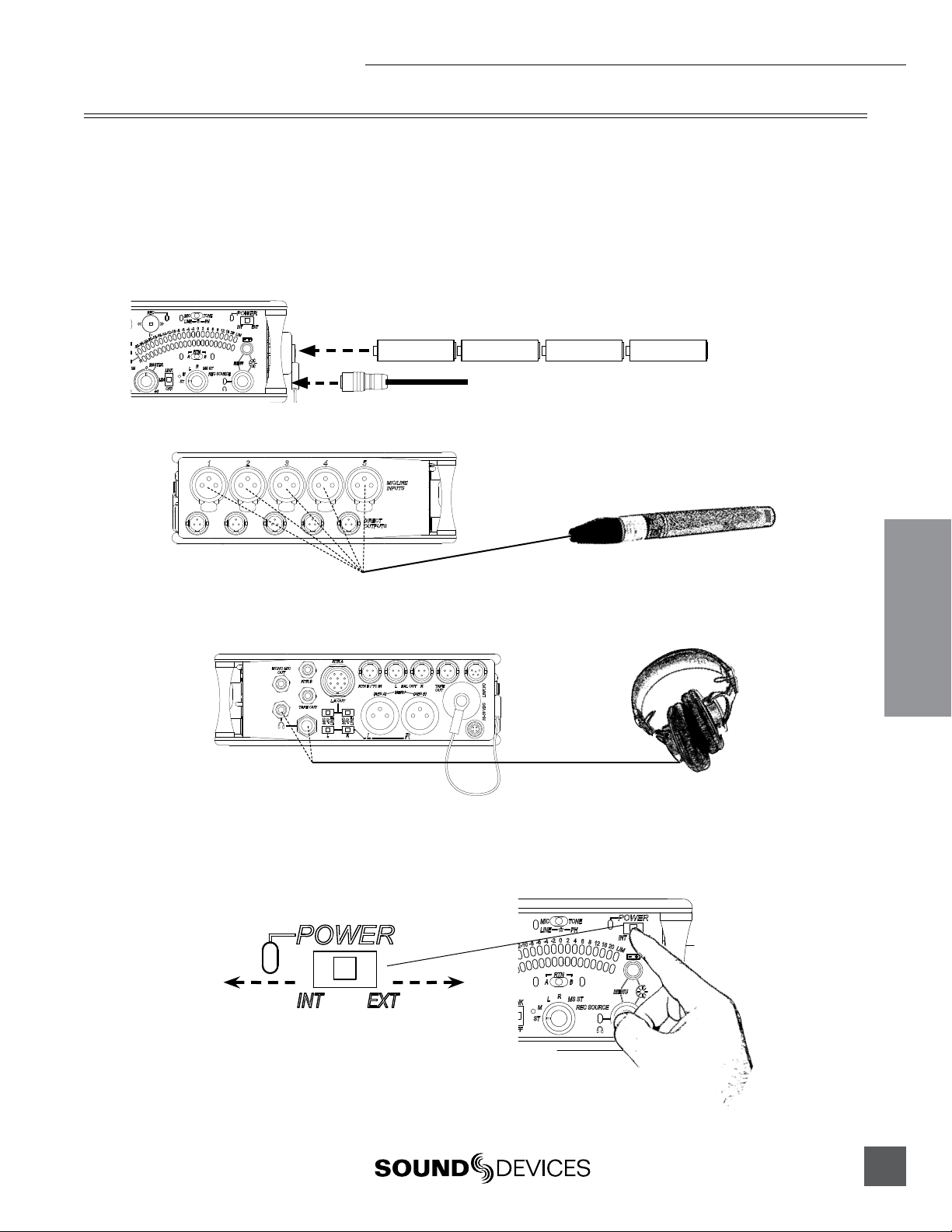
1) Connect power.
For internal powering from AA batteries, unscrew the battery cap (counter-clockwise), insert four AA batteries (not included) positive (+) side first into the battery
tube. Thread the battery cap back on (clockwise). For external powering, connect a
DC powering source (not included) to the DC connector on the Right Panel.
AA
-
+
+
AA
-
+
AA
-
+
AA
-
External Power Supply (not included)
2) Connect analog microphone or line sources to the XLR inputs.
552 Left Panel
3) Connect headphones to either the 1/4-inch or the 3.5 mm headphone outputs.
552 Right Panel
Quickstart
4) Power On the mixer.
Slide the power switch to the INT position to power the mixer from AA batteries.
Slide the power switch to the EXT position to power the mixer from external DC.
Slide left for Internal AA Battery
Slide right for External DC Power
3
Page 8
552 User Guide and Technical Information
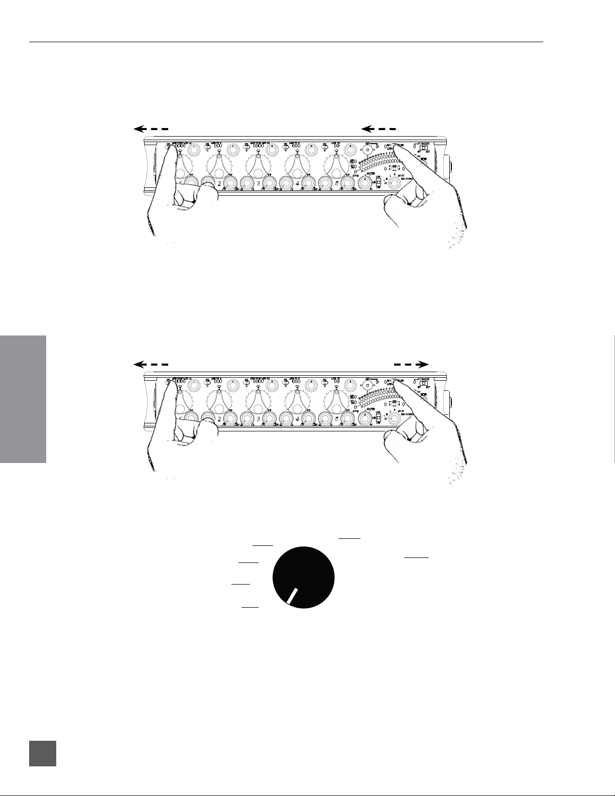
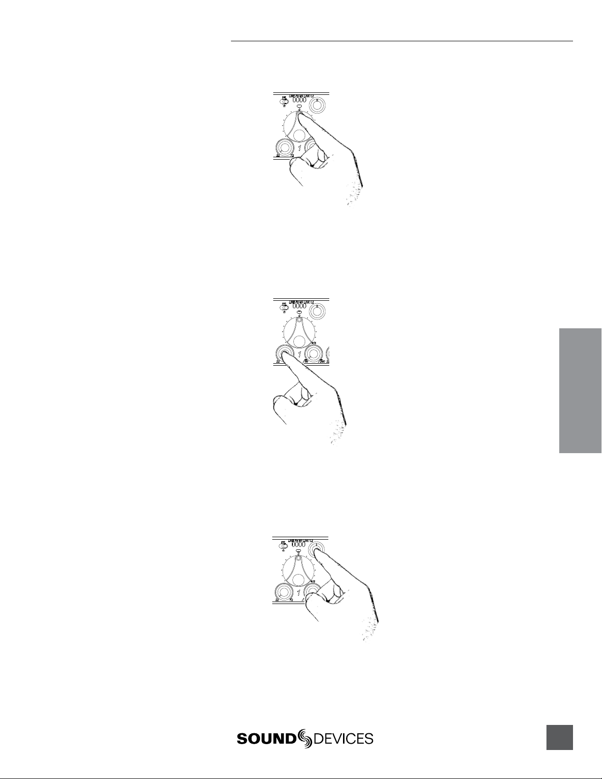
5) Set Input Type – Mic or Line Level.
To select an input to Mic or Line level, hold an input’s PFL switch, then slide the
SLATE MIC/TONE switch to the left. The input’s LINE LED illuminates blue when
set to line level and the LED is not illuminated when set to Mic level.
1) Hold the Input’s PFL. 2) Slide the SLATE MIC/TONE switch left.
6) Apply Phantom Power to an input.
The 552 supplies 48 V to inputs set to receive phantom power (PH). Phantom power can be set to 12 V in the Setup Menu. To apply phantom power, hold an input’s
PFL switch, then slide the SLATE MIC/TONE switch to the right. The input’s PH
LED illuminates blue when phantom power is applied.
Quickstart
1) Hold the Input’s PFL. 2) Slide the SLATE MIC/TONE switch right.
7) Select a headphone monitor mode using the Headphone Selector.
Right Program
Left Program
Mono (summed left and right)
Stereo (Left and Right) Program
MS Monitor Modes are useful to listen to left/right stereo when M and S signals are routed. When
inputs are linked as an MS pair in the Setup Menu use the ST (Stereo program) monitor mode; this will
already contain the decoded MS Stereo signal.
L
M
ST
R
MS ST
Stereo MS (mid-side)
REC Source
Recording Source
8) Set the headphone level.
Turn the Headphone Controller to set headphone levels. The currently selected
headphone level is briefly indicated on the right output meter when the Headphone level control is turned.
4
v. 1.4 Features and specifications are subject to change. Visit www.sounddevices.com for the latest documentation.
Page 9
552 User Guide and Technical Information
9) Set Input Faders in use to unity gain (0 dB or 12 o’clock).
Faders not used should be set to off (full counter-clockwise position).
10) Set Input Trim Levels.
Push to release the recessed Trim (gain) Control. Turn the Trim Control clockwise to
raise the level of the input. Once the gain has been set, push the Trim Control again
to recess the control and remove it from the mixing surface. Use the Input Fader to
make fine level adjustments.
11) Route each input to either Left or Right Outputs using the Input Pan Control.
Push to release the recessed Pan Control. Turn counter-clockwise to send the input
to the Left Output and turn clockwise to send it to the Right Output. Once the pan
has been set, push the Pan Control again to recess the control and remove it from
the mixing surface.
12) Set High-Pass Filters and Limiters.
Set the High-Pass Filter using the control adjacent to the Trim Control (full counterclockwise position is off). Activate the Limiters using the switch adjacent to the
Master Output Gain Control (Lim (dual Mono) Link (Stereo) applies to all inputs
and outputs).
Quickstart
5
Page 10
552 User Guide and Technical Information
13) Adjust LED Meter brightness.
Press and hold the Battery Check button while turning the Headphone Controller.
14) Check Internal and External power levels.
Press the Battery Check button to display the internal and external power levels
on the Output Meter LEDs. The internal AA battery level is displayed on the left
meter and external DC voltage level is displayed on the right meter.
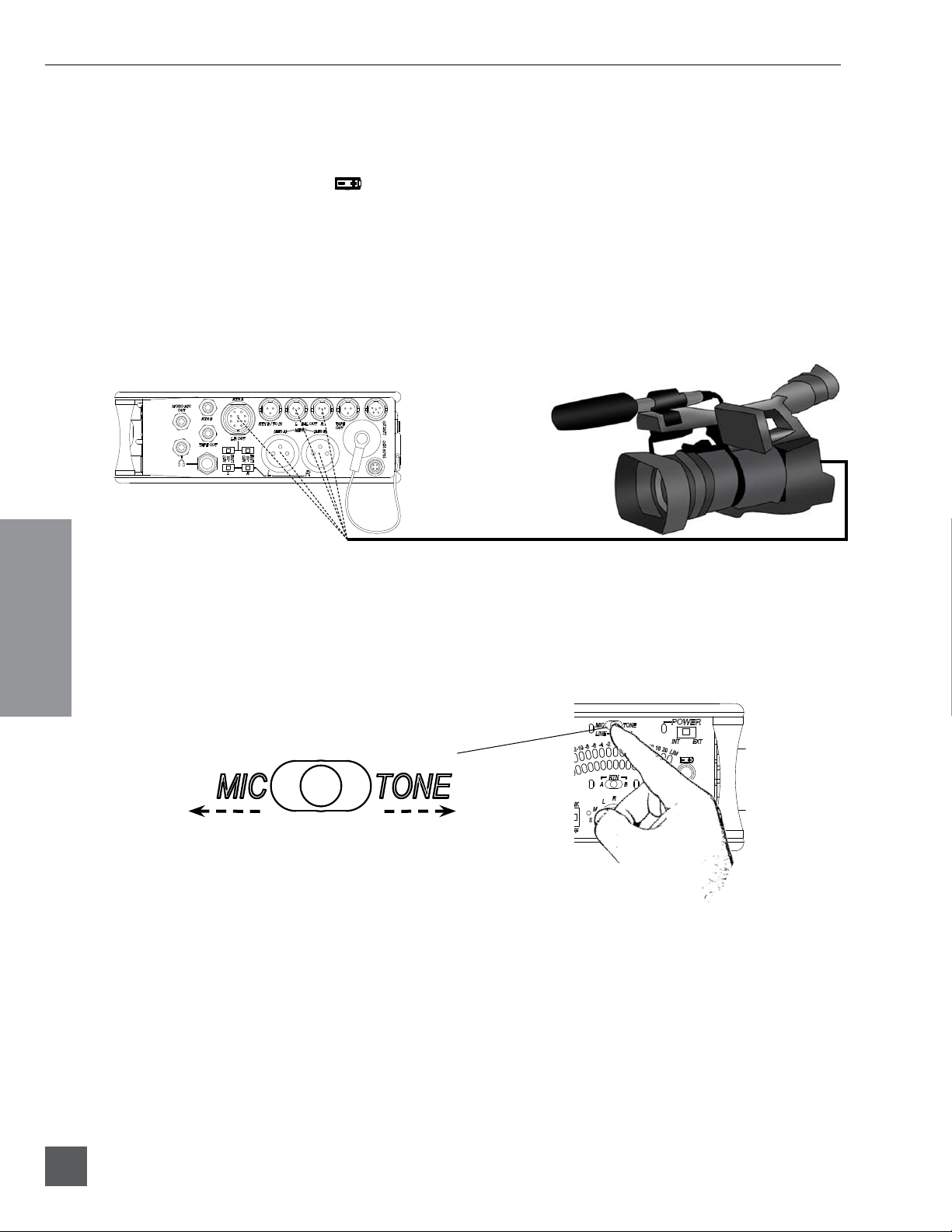
15) Connect the 552 analog outputs to the next device in the signal chain (audio
recorder, wireless transmitter, or camera).
Output levels are set (Line, -10, Mic) using the respective output’s attenuation
switch.
552 Right Panel
Quickstart
16) Set the next device’s input sensitivity to receive the supplied signal.
17) Activate the 552’s Tone Generator.
Slide the SLATE MIC/TONE switch to the TONE position. Tone latches on if the
switch is held for two seconds; slide right again to turn off. A 1 kHz tone is generated and is sent out at 0 dB (level and frequency are menu-adjustable).
Slide left for Slate Mic
Slide right for Tone.
18) Adjust the input gain on the next device accordingly.
6
v. 1.4 Features and specifications are subject to change. Visit www.sounddevices.com for the latest documentation.
Page 11
552 User Guide and Technical Information
Voice Prompt
The 552 features a Synthetic Voice for Enhanced Navigation, or SVEN. SVEN provides spoken word
feedback when Setup Menu features are adjusted. He is designed to simplify control and provide
important information to the user. Additionally, SVEN provides status information about the digital
audio recorder and time and date information. SVEN is routed only to the headphone outputs.
19) Setting the Time and Date.
Press and hold the Battery Check button for the mixer to announce in headphones
the current time and date. If the setting spoken back in headphones is incorrect see
Time of Day/Date Clock section of the 552 User Guide.
20) Insert an SD memory card into the back panel SD Slot.
Remove the protective rubber cover to access the SD memory card slot. Insert the
SD card into the slot until it sits securely in the slot. The card should glide smoothly
into the slot. Do not use excessive force when inserting the card and make certain
that the electrical contacts are facing downwards. Push on the card to remove it.
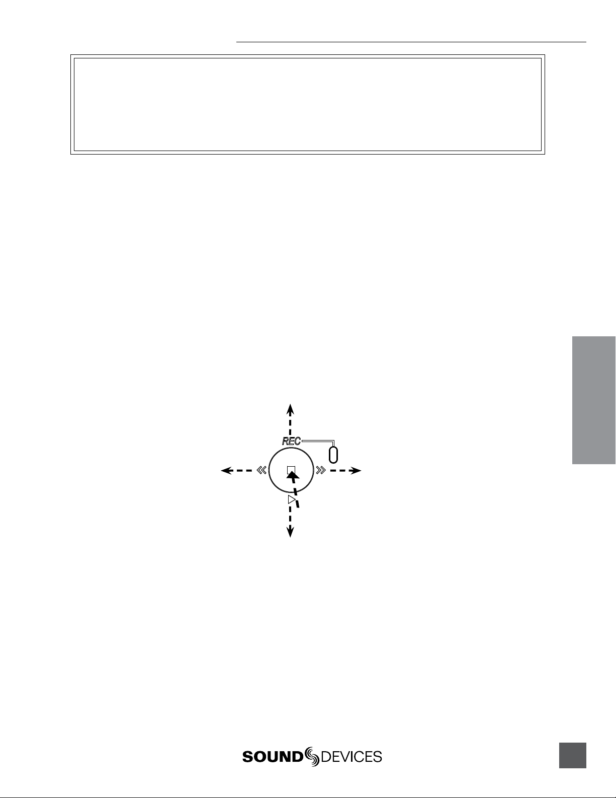
21) Controlling the Integrated Digital Recorder.
The Recorder Controller is used to initiate the Record, Stop, Playback, Rewind, Fast
Forward functions as well as to navigate through recorded files.
Push up to begin recording.
Push left to load the previous file.
Push left to Rewind during playback.
Press in to Pause/Stop
Push down to playback the last recorded file or loaded file.
Push right to load the next file.
Push right to Fast Forward during playback.
22) Making Changes in the Setup Menu.
The 552 has many features that are accessed through its Setup Menu. For details on
entering and controlling the Setup Menu see Accessing the Setup Menu section in
the 552 User Guide.
Quickstart
23) Power Down the Mixer.
Slide the power switch to the center position to power down. All settings are saved
to EEPROM and will be saved and recalled upon next power on whether or not the
unit is powered or has batteries.
7
Page 12
552 User Guide and Technical Information
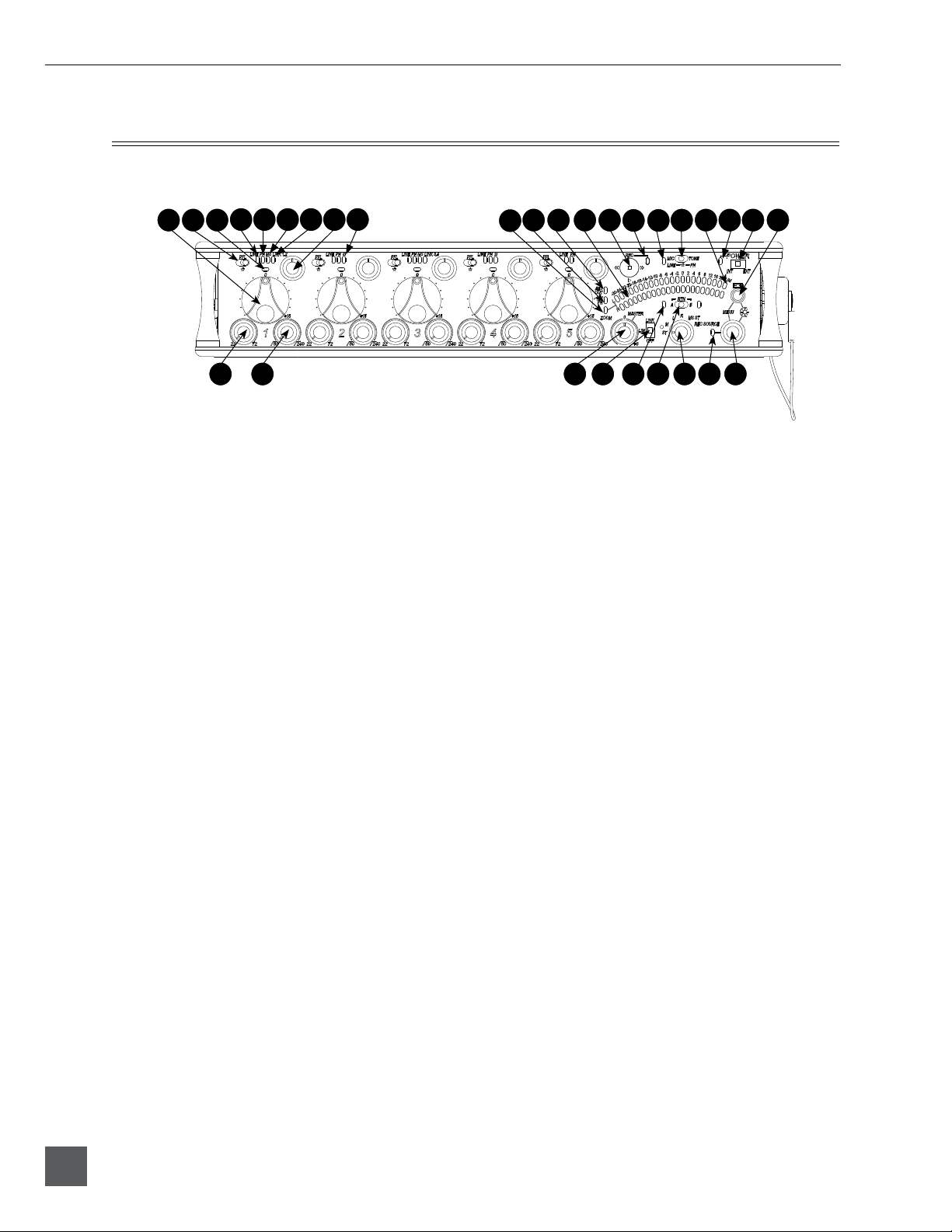
Front Panel Descriptions
All 552 settings are accessed and controlled from the Front Panel. This allows the unit to be placed in
a production bag while having complete control of the unit.
1
4
6 7 8 119 10
5
13 14 15 16
12
17 18
21 22 23
20
19
2 3 24 25 2726 28 29
1) Input Fader
Primary control for adjusting the level
of an input during operation. Ranges
from Off to +15 dB. Nominal setting is
in the middle (0 dB).
2) Gain (Trim)
Coarse input gain control. Sets the
initial input sensitivity level so that the
Input Fader can be used for fine gain
adjustments. Range is from +22 dB to
+72 dB. See Input Setup and Control.
High-Pass Filter Control
3)
Adjusts corner (-3 dB) frequency of
high-pass filter. Full counter-clockwise
position (detented) deactivates the
High-Pass Filter. Range is 80-240 Hz,
12 dB/oct to 6 dB/oct. See Input Setup
and Control.
4) PFL/Input Solo Switch
Pre-Fade Listen. Sends the input’s
pre-fade signal to headphones for solo
monitoring, troubleshooting, and gain
setting. Does not affect Master Output
signal. Slide the switch left to activate,
and again to deactivate. For momentary action, hold the switch left for one
second or longer. The Input Signal Activity LED flashes yellow when an input’s PFL is latched on. The Input PFL
Switch is also used to make changes to
several input settings. See Input Setup
and Control.
30
5)
Input Signal LED
Indicates input signal activity. LEDs illuminate in various colors and intensities to show signal level and activity.
Green = signal presence (pre-fader),
yellow = limiter activity (pre- and postfade) also flashes when solo is latched
on, red = signal overload/clipping
(pre- and post-fade) also solid when
input is muted. See Metering.
6) Mic/Line LED
Illuminates blue to indicate an input is
set to Line level. To toggle between Mic
and Line settings, hold the input PFL
then slide the Slate Mic/Tone Switch to
the Slate position.
7) PH/Phantom LED
Illuminates blue to indicate an input’s
phantom power is on. To toggle phantom power on and off, hold the selected
input’s PFL switch then slide the Slate
Mic/Tone switch to the Tone position.
Phantom power voltage can be set to
12 or 48 V (48 V is Factory Default).
Phantom voltage is set in the Setup
Menu. The phantom power voltage is
applied across all inputs with the PH
LED illuminated.
8) MS LED
Inputs 1, 2 and 3, 4 can be linked as an
MS pair. When a pair is linked, the MS
and LINK LED illuminate blue. Stereo
linking configurations are selected in
the Setup Menu. See Stereo Linking.
8
v. 1.4 Features and specifications are subject to change. Visit www.sounddevices.com for the latest documentation.
Page 13

552 User Guide and Technical Information
9) Link LED
Illuminates blue when Inputs are linked
as a stereo pair. Stereo linking configurations are selected in the Setup Menu. See
Stereo Linking.
10) Input Pan
Controls the Left/Right balance of the
input signal to the outputs.
11) Input Polarity (Inputs 2 and 4 only)
Illuminates blue when the Input’s polarity is reversed. To toggle the state of the
input polarity, hold the selected input’s
PFL then press the Battery Check button.
12) Zoom LED
Illuminates blue when the Output Meter
is in Zoom Mode. Zoom Mode allows
the user to view higher resolution in the
0 to +20 dBu range on the Output Meter.
To toggle Zoom on and off, press in on
the Headphone Controller. The Zoom
Function is defeated in the Setup Menu
Function Meter Ballistics. See Metering.
13) Time Code LED
Time Code is selected from the Setup
Menu. When on, the LED flashes blue
when Time Code is active but not being
received The LED Illuminates solid blue
when the unit is receiving valid time
code. Time Code is connected to the
RTN B TA3 connector and is stamped to
files generated by the 552’s recorder. See
Time Code.
14) AES Out LED
Illuminates blue when one or more of
the AES outputs is active. See Digital
Outputs.
15) Output Meter
Multi -segment LED output meter. Scale
is normally -30 dBu to +20 dBu. In Zoom
Mode, scale changes from 0 dBu to
+20 dBu. To engage Zoom mode, press
in on the Headphone Controller. See
Metering.
16) Recorder Controller
Controls the Integrated Digital Recorder. Record Mode is enabled in the
Setup Menu. When enabled, push up
to Record, press in to Pause/Stop, push
down to Play, push left to Rewind, push
right to Fast Forward. See Digital Audio
Recorder.
17) Record LED
Indicates the status of the recording media. The LED is off when the recorder is
in standby mode. Flashes yellow when
no SD card is inserted. Illuminates solid
red while recording, flashes red when
record is pending. Illuminates solid
green while in playback mode. Flashes
green while playback is paused. Illuminates solid yellow when media is busy.
The LED is off when recorder is off.
18) Slate/Tone LED
Illuminates yellow when either the slate
mic or tone is latched on.
19) Slate Mic/Tone Switch
Slide left to activate the Slate Microphone, slide again to deactivate. For
momentary action hold for one second
or longer. Slide Slate Mic/Tone switch
right to activate the Tone Oscillator. Tone
will latch if held for 2 seconds or longer,
slide again to deactivate. This switch
also functions as input type and phantom power select. See Tone Oscillator/
Slate Mic. See also Talk Back for additional
features.
20) Limiter LED
Each Output has its own Limiter LED.
The LEDs Illuminate yellow when the
Output Limiter is active. See Output
Limiter.
21) Power LED
When powering with internal AA batteries, the LED illuminates green when
the 552 is on, turns yellow when low
voltage point is reached, and flashes
red when voltage reaches a critical level
and batteries should be changed. When
powering with external DC, the LED
illuminates green when the 552 is on,
flashes red when voltage drops below
the set threshold. See Powering.
9
Page 14
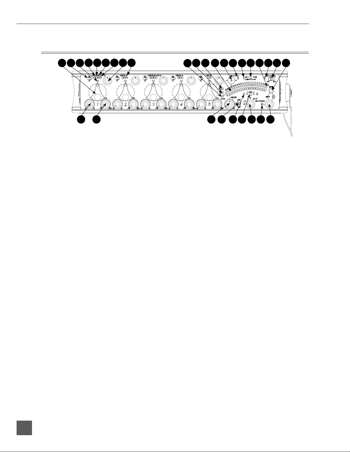
552 User Guide and Technical Information
Front Panel Descriptions cont.
1
4
6 7 8 119 10
5
2 3 24 25 2726 28 29
22) Power Switch
Three-position slide switch, selects between internal battery power or external
DC sources, middle position is Off.
23) Battery Check Button
Press to display internal and external
voltage levels on the Output Meter.
Secondary function acts as shift key for
various front panel features. Press and
hold to announce card space available
and current time and date.
24) Master Output Level Control
Controls the overall signal level of the
Master Stereo Outputs. Adjustable from
off to +6 dB. See Outputs.
25) Limiter Switch
Activates both Input and Output Limiters. When LIM is selected, the Output
Limiters act independently on the Left
and Right Outputs. When LINK is
selected, the Output Limiters are linked
and limiting is applied evenly across the
Stereo Outputs. See Limiter.
26) RTN A/B LED
Indicates the activity for each return
input. The LEDs illuminate in various
colors and intensities to indicate the behavior of the return signals. Green = return signal presence, Red = return signal
overload/clipping, Yellow = the monitor
return is latched on. When time code is
active, the TA3 input is used exclusively
for time code. The 3.5 mm jack functions
normally. See Return.
13 14 15 16
12
17 18
19
27) RTN A/B Switch
Two-position momentary switch. Slide
left for RTN A headphone monitoring,
slide right for RTN B headphone monitoring. Slide again to deactivate. For momentary action, hold for one second or
longer. While holding the return switch,
turn the Headphone Controller to adjust
RTN A and RTN B levels. When time
code is active, the TA3 input is used exclusively for time code. The 3.5 mm jack
functions normally. See Return and also
RTN Loopback and Time Code.
28) Monitor Selection Switch
Selects program sent to the headphone
monitor. ST = stereo program, M =
mono summed mix of Left and Right
program, L = mono mix of Left program,
R = mono mix of Right program, MS
ST = decoded MS Stereo, REC Source =
program routed to the recorder (AES A).
See Headphones.
29) Headphone Peak LED
Illuminates red when the headphone
monitor is approaching clip levels.
30) Headphone Controller
Controls headphone gain. Secondary
functions include Setup Menu control,
Zoom Mode, LED Brightness adjustment, and Return levels control.
20
21 22 23
30
10
v. 1.4 Features and specifications are subject to change. Visit www.sounddevices.com for the latest documentation.
Page 15
Rear Panel Descriptions
552 User Guide and Technical Information
1 2
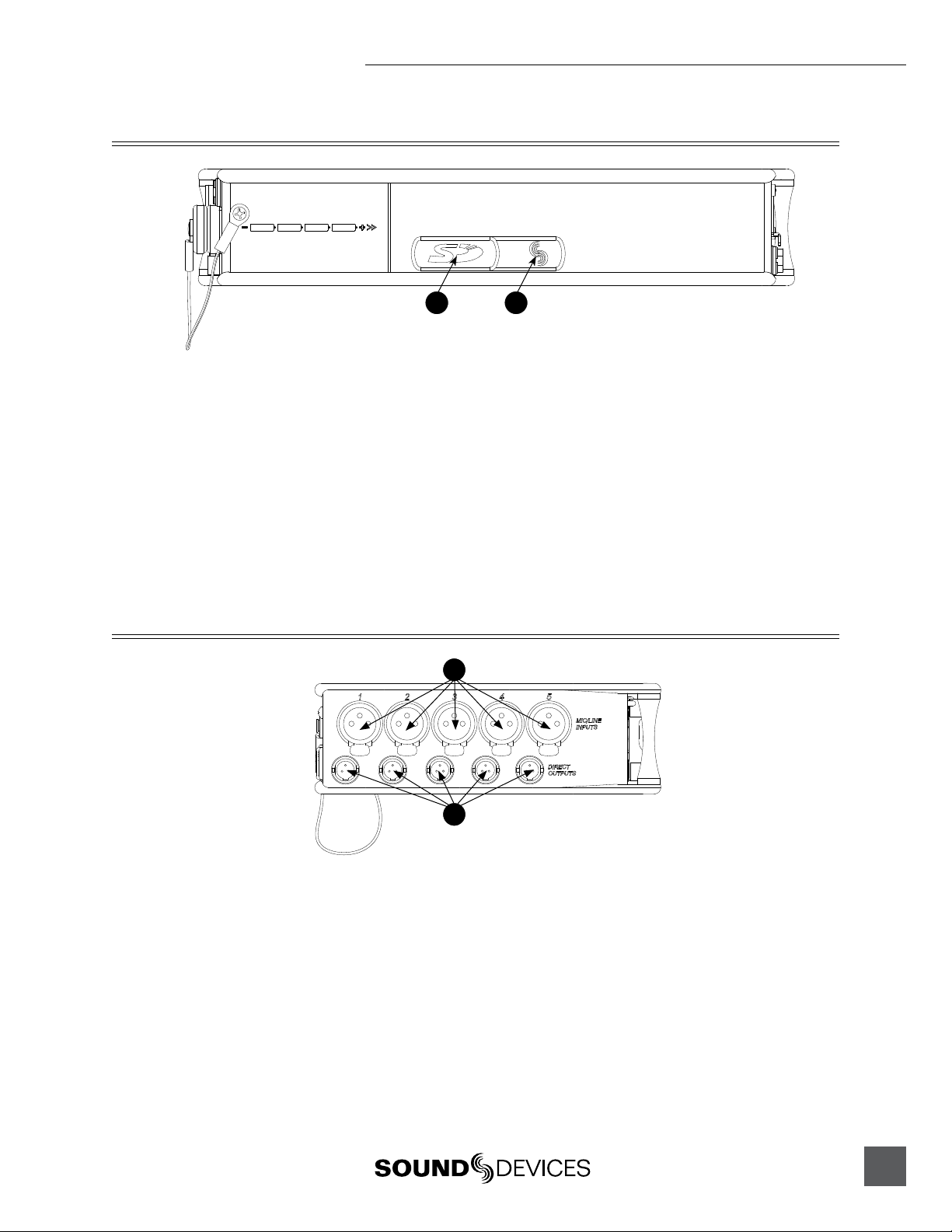
1) SD Slot
Protective rubber cover for SD (Secure
Digital) memory card slot. Insert the
SD/SDHC card into the slot until it sits
securely in the slot. The card should
glide smoothly into the slot. To remove
the card, push to eject. MMC and SDXC
cards are not supported.
Left Panel Connectors and Controls
1
2
1) Factory Programming Port
Mini USB port used for initial factory
programming. This connection has no
user function.
1) Analog Inputs Channels 1-5
Transformer-balanced analog microphone- or line-level inputs 1-5 on XLR
connectors. Pin 1 = Ground; pin 2 = Hot
(+); pin 3 = Cold (-). For unbalanced
inputs, tie pin 1 and pin 3 together =
ground, pin 2 = positive. Make certain phantom power is off when using
unbalanced inputs. See Input Setup and
Control.
2) Analog Direct Outputs
Balanced direct outputs on TA3 connectors. Slate Mic and Tone signals
appear at the direct outputs. Direct
output signal is pre- or post-fader and
level is selected in the Setup Menu between Line, -10, and Mic levels. Pin 1 =
Ground; pin 2 = Hot (+); pin 3 = Cold (-)
float pin 3 to unbalance.
11
Page 16
552 User Guide and Technical Information
Right Panel Connectors and Controls
1 2
10 11 12 13 14
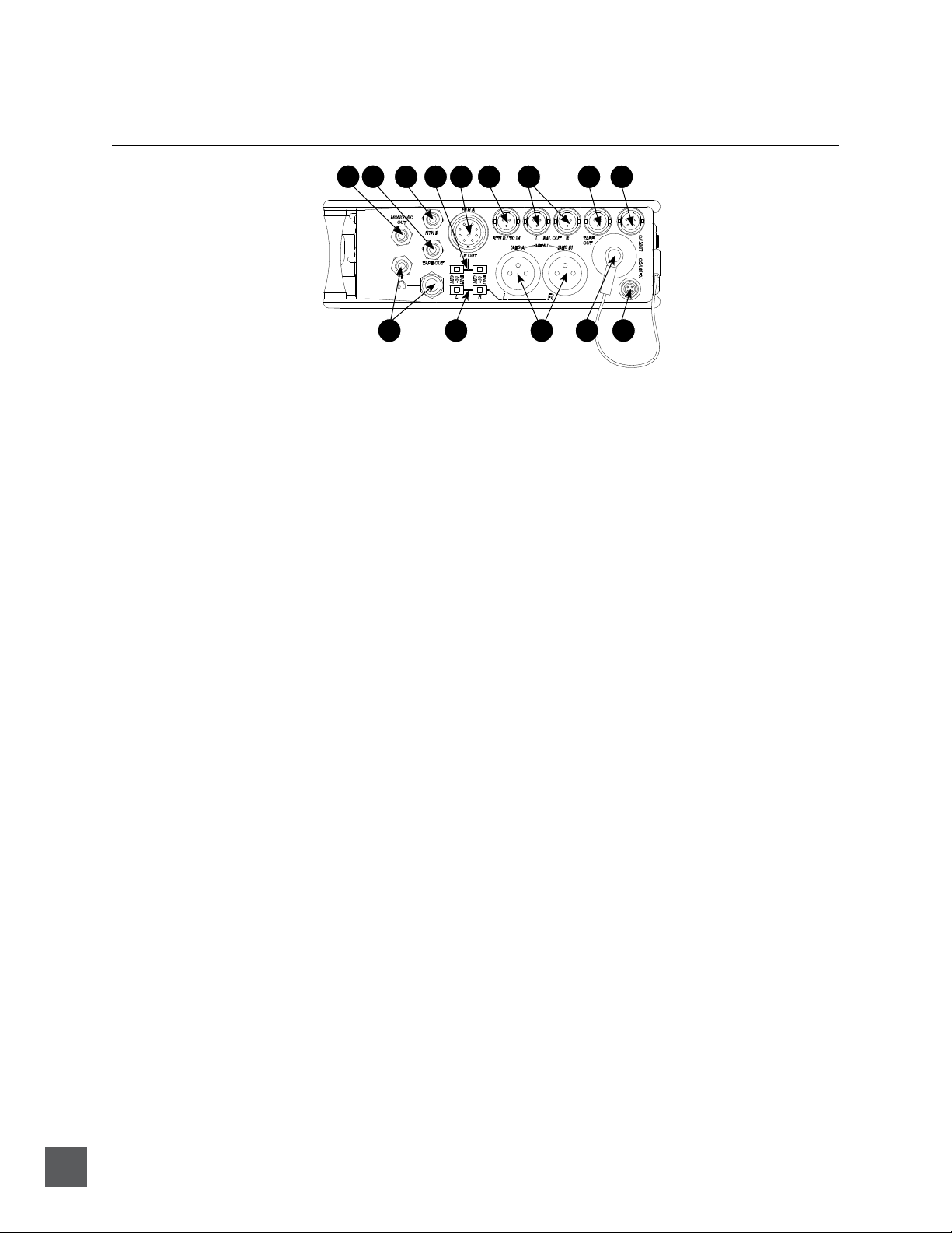
1) Mono Mic Out
Unbalanced mono mic-level output on
3.5 mm female connector, designed to
connect to wireless IFB transmitters or
transcription recorders. Tip = Hot (+),
Sleeve = Ground.
2) Tape Out
Unbalanced stereo output on 3.5 mm
female connector. Sleeve = Ground,
Tip = Left, Ring = Right.
3) RTN B In
Unbalanced stereo 3.5 mm female connector for Return B audio input. Sleeve
= Ground, Tip = Left, Ring = Right. See
RTN B and RTN Loopback Mode.
4) 10-Pin Output Level Switch
Selects the Hirose 10-Pin Output level
between Line, -10, or Mic levels.
3 4 5 6 7 8 9
8) Tape Output
Unbalanced tape-level stereo output
on TA3 connector. Pin 1 = Ground,
pin 2 = Left, pin 3 = Right.
9) Link I/O
Used to link additional Sound Devices
552, 302, 442, or MixPre mixers. See
Mixer Linking.
10) Headphone Outputs
1/4-inch and 3.5 mm stereo connectors,
drive headphones from 8-2000 ohm
impedances. 3.5 mm connection can be
set in the Setup Menu as an independent
boom operator send. See Talk Back Mode.
11) XLR Output Level
Sets the nominal output level for the
Left and Right XLR Master Output to
Line, -10, or Mic levels.
12
5) 10-Pin Master Outputs and Return A
10-pin connector includes second master
output (transformer-isolated from the
XLR outputs) and unbalanced stereo
Return A. Can be set to send out AES
digital signals. See AES Digit Outputs.
6) RTN B / TC Input
Unbalanced stereo input for Return B
audio and Time Code input on TA3 connector. RTN B wiring pin 1 = Ground,
pin 2 = Left, pin 3 = Right. Time Code
wiring pin 1 and 3 = ground, pin 2 = Hot
(+). See Time Code.
7) TA3 Master Outputs
Line, -10, or Mic level selected in the
Setup Menu. Pin 1 = Ground, pin 2 =
Hot (+), pin 3 = Cold (-) float pin 3 to
unbalance.
v. 1.4 Features and specifications are subject to change. Visit www.sounddevices.com for the latest documentation.
12) XLR Master Outputs
Transformer-balanced analog outputs on standard 3-pin XLR connectors. Pin 1 = Ground; pin 2 = Hot (+);
pin 3 = Cold (-). Unbalance by tieing
pin 3 to pin 1. Can be set to send AES3
digital signals in the Setup Menu. See
AES Digit Outputs.
13) Battery Compartment
Holds four AA batteries required for
internal powering. Accepts Lithium,
Alkaline, and NiMH rechargeable cells.
14) DC Input
Accepts DC voltages from 10–18 V for
mixer powering. Pin 1 = Negative (–),
pin 4 = Positive (+). Ext DC is completely isolated (floating) from the rest of the
circuitry.
Page 17
Top and Bottom Panels
1 2
552 User Guide and Technical Information
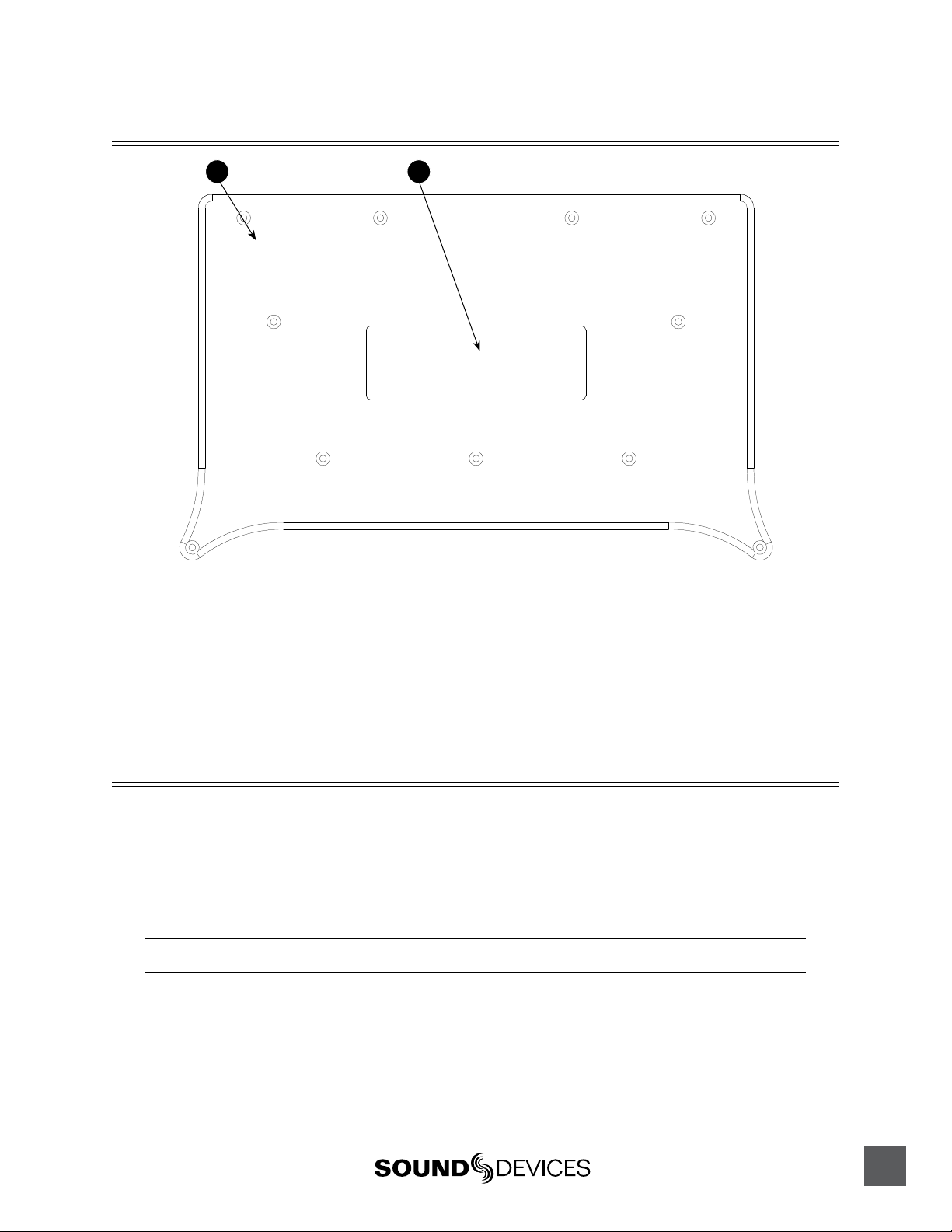
1) Top and Bottom Panels
Made of molded carbon fiber, this highly
specialized composite has nearly identical strength-to-weight properties as
die-cast magnesium. Additionally, the
material also has the natural RF shielding abilities similar to aluminum.
2) Product Badge
The product badge on the bottom panel
can be covered with a customized identity tag. The label place holder on the
bottom panel conforms to the 4” x 1.33”
Avery label #5162 standard. Third party
software for Avery label #5162 templates
are available online.
Voice Prompt
The 552 features a Synthetic Voice for Enhanced Navigation, or SVEN. SVEN provides spoken word
information in headphones when Setup Menu features are adjusted. SVEN is designed to simplify
control and provide important information to the user. Additionally, SVEN provides status information about the digital audio recorder and time and date information. SVEN is sent only to the headphone outputs. If Talk Back Mode is selected, SVEN only appears on the 1/4” headphone output. See
Talk Back for details.
The 3.5 mm headphone output does not receive SVEN announcements when Talk Back Mode is active.
13
Page 18
552 User Guide and Technical Information
The following information is reported by the SVEN.
Function Description
Card Space Available
Time and Date
Time Date Set
Setup Menu Navigation
Playback Navigation
Media Busy Indication
Full SD Card
Record Mode Off
Next File
Press and hold the Battery Check button to announce the remaining card space available. SVEN
automatically announces remaining record time at 15, 10, 5, and 2 minutes remaining.
Continue to hold the Battery Check button after Card Space Available announcement to hear the
current time and date.
Hold Input 5’s PFL then press the Battery Check button and the Headphone Controller to enter
Time Date Set. The unit of time and each value is announced when turning Headphone Controller.
While in the Setup Menu, the current Function or Option is announced with each turn of the
Headphone Controller.
Announces the file number of the selected file. If navigating through folders, SVEN announces the
selected daily folder.
“Media Busy” is announced if the SD card is not available to respond to a command.
“Full SD Card” is announced when there is no space remaining on the SD card and a record command has been given.
“Record Mode Off” is announced if the recorder receives a command and the recorder is disabled
in the Setup Menu.
Press the Recorder Controller in stand-by mode to announce the file number of the next take to
be recorded.
Input Setup and Control
The 552’s inputs consist of five, full-featured preamplifiers. Each input has a wide gain range to accommodate nearly all signal types of microphone and line. The 552 easily accepts signals from lowsensitivity ribbon and dynamic microphones, medium-level wireless and condenser mic outputs,
and “hot” line-level signals.
The XLR inputs of the 552 are transformer-balanced. The isolation characteristics of transformers are
superior to other balancing techniques and are ideal for the hostile and uncontrolled environments
of field production. Transformers provide galvanic isolation from the driving source, meaning there
is no direct electrical connection. Signals are “transformed” magnetically. The input transformers in
the 552 use premium magnetic core material to achieve high signal-handling-capability (especially at
low frequencies) while keeping distortion to a minimum. Because of their inherently-high common
mode impedance, transformers are unrivaled by any other type of input for common-mode noise
rejection.
The inputs of the 552 can be used as balanced or unbalanced. To unbalance, tie pin-3 to pin-1 of the
XLR connector. There is no change in gain between unbalanced and balanced connections into the
552.
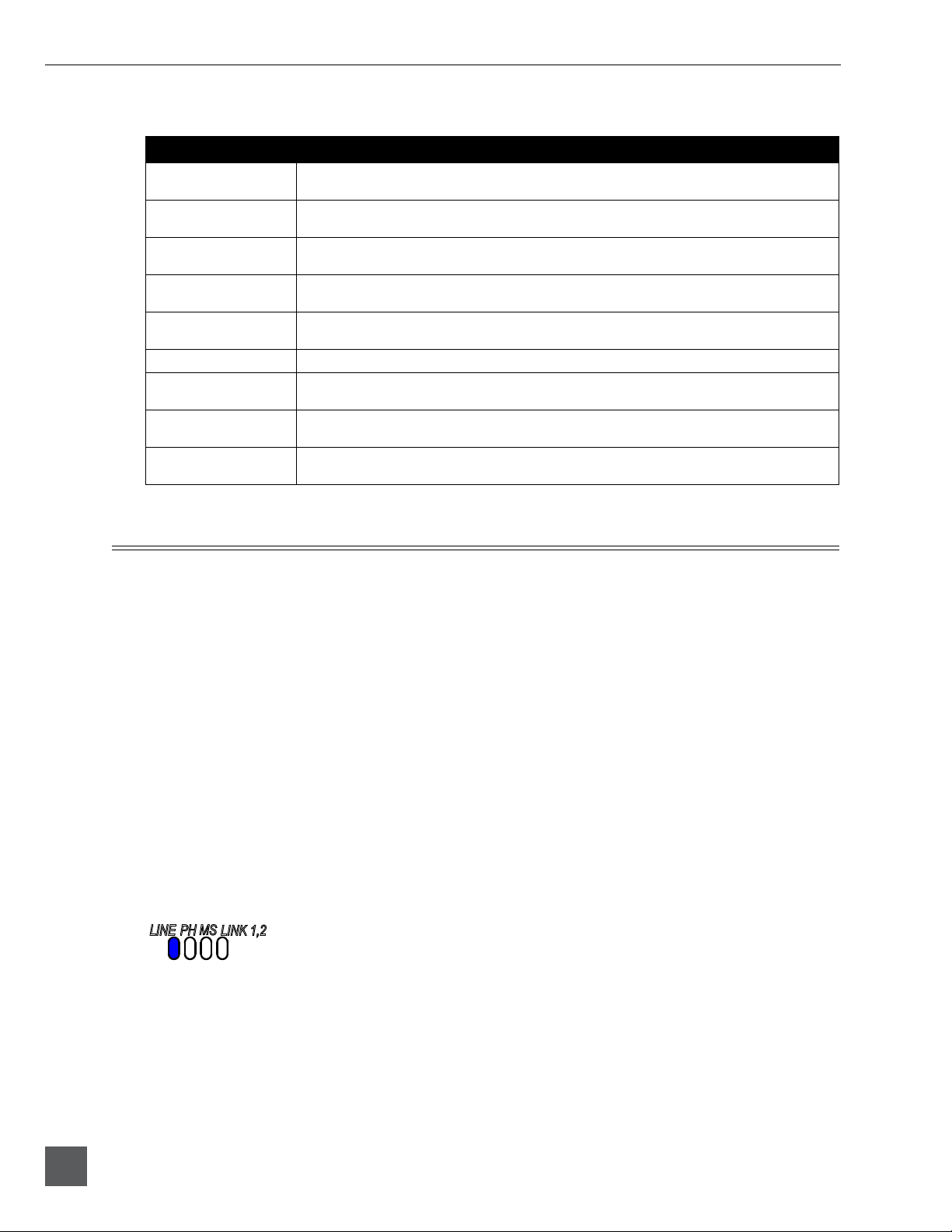
Mic/Line Selection
Two input modes are available, Mic and Line . When Line is selected the LINE LED is illuminated.
Taking into account all gain stages, the 552 has 93 dB of available gain from Mic input to Line output.
When inputs are set to the LINE position, the input sensitivity is reduced by 40 dB.
14
The selected channel is set to receive a line level input when the Line LED adjacent to the input’s PFL
is illuminated. To toggle between Mic/Line levels, hold the respective input’s PFL and then slide the
Slate Mic/Line switch to the Slate position.
v. 1.4 Features and specifications are subject to change. Visit www.sounddevices.com for the latest documentation.
Page 19

552 User Guide and Technical Information
1) Hold the Input’s PFL. 2) Slide the SLATE MIC/TONE switch left.
Phantom Power
Phantom powering is a fixed DC voltage of either 12 or 48 Volts. This voltage is resistively applied to
pin 2 and pin 3 of an input’s XLR connector, relative to pin 1. In this configuration, there is no voltage difference between signal pins 2 and pin 3.
The phantom voltage is selectable between 12 and 48 Volts in the Setup Menu. The selected voltage
level applies to all inputs with phantom power enabled. Phantom power voltage is 48V at factory
default. See Setup Menu.
Phantom power can be activated individually for each input. To enable or disable phantom power, press and hold the respective input’s PFL switch then momentarily slide the Slate Mic/Tone
switch to the Tone position. The respective input’s PH LED illuminates when phantom is enabled.
1) Hold the Input’s PFL. 2) Slide the SLATE MIC/TONE switch right.
Phantom power is only applied to inputs set for Mic level at factory default. Phantom Power can be
applied to inputs set to Line- and Mic-Level in the Setup Menu. This is useful when using microphones in high SPL environments.
Make certain to disable phantom power with Line-level output devices that are susceptible to damage
from DC.
The 552 can provide up to 10 mA to each input at 48 V, sufficient for the most power-hungry condenser microphones. Many phantom powered microphones do not require 48 V and can be properly
powered with 12 V. When acceptable, use 12 V phantom to extend the 552’s battery life.
If Phantom Power is not required, for instance with dynamic microphones, it is best practice to disable it. Phantom power can capacitively couple noise into the mic inputs with poor mic cables. When
15
Page 20

552 User Guide and Technical Information
disabled, no voltage is applied to the microphone input. Do not apply power to ribbon microphones,
improperly wired cables can permanently damage the microphone.
Gain - Trim and Fader Relationship
The gain of an input is adjusted by two controls, Input Trim and Input Fader. This two-stage architecture is identical the to topology of mixing consoles and provides a great deal of flexibility. Input
Trim is often thought of as a course gain control and the Input Fader as the fine gain control.
Input Trim
The 552’s input sensitivity is set with the pop-up knob Trim control. With the Input Fader set to unity
gain (0 dB or 12 o’clock), make the appropriate adjustments using the Trim control. Once the coarse
gain is set to the desired level, recess the Trim control to hide it from the 552’s mixing surface. Trim
level is adjustable from 22 to 72 dB of gain.
Input Fader
The Input Fader is the primary control used during mixing operation. Use the Input Fader to make
fine gain adjustments during operation. The fader can be attenuated from off (full counter-clockwise
position) to +15 dB above the set Trim level (full clockwise position). To optimize gain structure for
the best noise performance operate input faders at or near the 0 dB (unity gain) position.
High-Pass Filter
Each input channel has an adjustable high-pass filter controlled by the High-Pass Filter pop-up knob.
High-pass (or low-cut/low roll-off) filters are useful for removing excess low frequency energy from
audio signals. Wind noise is a common unwanted low frequency signal that can be reduced with
the use of a high-pass filter. For most audio applications engaging the high-pass filter is beneficial,
because audio information below 100 Hz is rarely used, especially for speech reproduction.
The 552’s high-pass filter circuit features an adjustable corner (-3 dB) frequency over a range from 80
to 240 Hz. Below 80 Hz, the filter’s slope is 12 dB/octave. At higher corner frequency settings, the
slope is 6 dB/octave. See Specifications. The purpose for this compound slope is to give additional
roll-off at the 80 Hz setting to reduce wind noise and low frequency rumble. The higher settings can
be used to counteract the proximity effect of directional microphones where a more gentle slope is
desired.
When engaged or disengaged, the high-pass filter gradually fades into the selected state. This prevents sudden obvious pops in the audio.
16
The 552’s high-pass filter circuit is unique because of its placement before any electronic amplification. Most mixer’s high-pass filter circuits are placed after the microphone preamplifier, such that all
of the low-frequency signals get amplified. By virtue of the 552’s circuit cutting the low-frequency
signals before amplification, higher headroom is achieved in the presence of signals with significant
low-frequency energy.
v. 1.4 Features and specifications are subject to change. Visit www.sounddevices.com for the latest documentation.
Page 21

552 User Guide and Technical Information
When possible, attempt to equalize at the sound source with microphone selection, placement,
windscreens, and onboard microphone filtering. Many microphones have on-board high pass filters.
Use the high-pass filters on the 552 in conjunction with the microphone’s filter to increase the filter’s
slope.
The filter can be removed from the circuit completely by moving the high-pass filter control to the
full counter-clockwise (detented) position. The high-pass filter potentiometer can be adjusted easily
and then recessed to hide it from the mixing surface.
Pan Control
The pop-up knob control routes inputs to the left and right output buses. For most applications, a
channel will be panned either hard-left, hard-right, or center. The pan pot has a detent in the center
position. After setting the pan, the pan control can be recessed to hide it from the mixing surface during normal operation.
Input Polarity
The polarity (sometimes referred to as a phase inversion) of inputs 2 and 4 can be reversed. Polarity
reversal is used to compensate for incorrectly wired balanced cables, to prevent signal cancellation
when a source is dual-miked from opposite directions, or to reverse left/right with MS microphones.
To toggle between normal and reverse polarity, activate the respective input’s PFL then press the
Battery Check Button. When the front panel Input Polarity LED is lit, the polarity is reversed on that
channel.
1) Hold the Input’s PFL.
2) Press the Battery Check Button.
17
Page 22

552 User Guide and Technical Information
Stereo Linking
The Stereo Link feature allows two pairs of 552 inputs to be linked as stereo pairs. These are inputs
1,2 and inputs 3,4. In the Setup Menu inputs can be linked as either a Stereo Pair or an MS Stereo
Pair. Input Linking is indicated by the odd channel’s (1 and 3) LINK LED. When an input pair is
linked as an MS pair, both the Link and MS LEDs will be lit.
Stereo Pair Linking
When Stereo Linking, input channels 1 and 2 and/or channels 3 and 4 act as a single stereo pair, controlled by the odd channel’s Fader. The odd channel’s Pan control acts as the balance control between
left and right. The even channel’s Fader and Pan controls are not active when inputs are linked. The
Trim control and High-Pass Filters continue to act independently of each other. When linked, the
channel’s Input Limiters are also linked. When inputs are linked as a stereo pair the odd input’s Link
LED is illuminated.
MS Pair Linking
When Linking inputs as an MS pair, channels 1 and 2 and/or channels 3 and 4 are linked as an MS
pair. The odd input (1 and 3) is the Mid signal and the even input (2 and 4) is the Side signal. The
odd channel’s Pan Control functions as a left/right balance control for the matrixed MS signal. The
even channel’s Fader and Pan controls are disabled. Each channel’s Trim control and high-pass filter
continue to act independently of each other. Use channels 1 and 2’s Trim controls to vary the Mid
and Side levels respectively. When linked, the Input Limiters are also linked. When inputs are linked
as an MS pair the odd input’s Link and MS LEDs will illuminate blue.
Input Muting
Any input can be removed from the mix so that its signal is not sent to the master left and right outputs. An input that is removed from the mix in this way is still present in the direct output and the
isolated input selections for AES A source. See AES Digital Outputs fr details.
18
1) Press in on the headphone controller
v. 1.4 Features and specifications are subject to change. Visit www.sounddevices.com for the latest documentation.
2) Press the input’s PFL.
Page 23

552 User Guide and Technical Information
Output Setup and Control
The 552 has stereo output bus that feeds multiple outputs. Additionally, each 552 input has its own
direct output. This output flexibility is essential for complex, multi-camera productions.
Master Gain Control
The Master Gain Control adjusts the overall output level of the left and right outputs. The gain range
of the Master Gain Control is from Off to +6 dB of gain. For most applications the Master control
should be set at the unity gain (0) position. The master gain is on a pop-up knob so it can be set and
hidden from the main surface. It is best practice to hide the Master Gain Control so that inadvertent
adjustments are avoided.
Master Outputs
The master outputs consist of three sets of connectors XLR, TA3, and Hirose 10-pin. The XLR and 10pin outputs are transformer-balanced, each driven from their own transformer windings for excellent isolation. Each output can be independently set to Line (+4 dBu nominal), -10, or Mic level (40
dB of attenuation versus Line). The master outputs are capable of driving long cable runs.
XLR
The XLR outputs are generally used as analog outputs but can be selected for AES3. At Factory
Default, the XLR Outputs are analog. Each XLR connector is configured in the Setup Menu to output
an AES3 digital signal. See AES Digital Outputs for details. When set as analog, the XLR labeled L will
output the Left program, XLR labled R will output the Right program. Each output can be set to
output at Line, -10, or Mic levels using the adjacent level switches.
TA3
The TA3 master outputs, located above the XLR Master Outputs, are an additional set of master
outputs. These outputs are active-balanced and can be used as either balanced or unbalanced. The
output level is set between Line, -10, and Mic levels from the Setup Menu. At Factory default, the
output level of the TA3 Master Outputs is Line Level.
Hirose 10-Pin
The 10-Pin outputs are used as either analog or digital outputs. At Factory Default, the 10-Pin Outputs are analog. Each output is configured in the Setup Menu to output an AES digital signal. See
AES Digital Outputs for details.
The Hirose 10-Pin connector contains balanced analog Left and Right outputs. The output level is
selectable between Mic, -10, and Line levels using the level switches located directly below the con-
19
Page 24

552 User Guide and Technical Information
nector. The Hirose 10-Pin also includes an unbalanced stereo return (RTN A) input for headphone
monitoring. The Sound Devices XL-10 Breakout Cable is an available accessory that provides easy
access to the balanced outputs and stereo RTN A connection of the 10-pin Hirose connector. See RTN
and Connector Pin Assignments for details about the Hirose Multi-Pin connector.
Direct Outputs
Each input channel has its own balanced TA3 Direct Output connection. These outputs are used to
send the isolated channel’s audio to another destination. The Direct Output signal is menu-selectable
as either pre- or post-fader. When activated, the Slate Microphone and Tone Oscillator signals are
also sent to the Direct Outputs. The nominal output level is selectable in the Setup Menu as Mic, -10,
or Line level. See Setup Menu.
Tape Outputs
Tape Outputs are typically used to interface with consumer devices such as MiniDisc and compact
transcription recorders. The 552 includes two unbalanced tape level outputs, a TA3 connector and
a 3.5 mm jack. These two connectors are resistively in parallel and are isolated from the balanced
outputs.
Tape Outputs, by default, send the Left and Right stereo program. Using the RTN Loopback function, the Tape outputs can be used to send the incoming RTN A or RTN B signals directly to receiving
devices. See RTN Loopback for more details.
Mono Mic Output
The Mono Mic Output is a summed mix of the left and right output channels. The 3.5 mm female
connector outputs a mono, mic-level signal intended for connection with portable transcription
recorders and wireless IFB transmitters.
Using the RTN Loopback function, the Mono Mic output can be used to send the incoming RTN A or
RTN B signals directly to receiving devices. See RTN Loopback for more details.
AES Digital Outputs
Each of the XLR or 10-pin Hirose outputs can be configured in the Setup Menu to output AES3
digital signals. The front panel AES Out LED is lit when one or both of the XLR or the 10-Pin outputs
are selected as digital outputs. The Left XLR or 10-pin output contains the two-channel AES A pair,
the Right XLR or 10-pin output contains the two-channel AES B pair. The selected output connector’s
Level Switch should be set to Line when using it as a Digital Output. In the Setup Menu, the following routings can be sent to each one of the AES pairs. Program before the comma appears on the
left-side of the AES Output and program after the comma appears on the right.
• Left Program, Right Program
• Channel 1, Channel 2 Pre-Fade
• Channel 1, Channel 2 Post-Fade
• Channel 3, Channel 4 Pre-Fade
• Channel 3, Channel 4 Post-Fade
• Channel 5 Pre-Fade, Left Program
• Channel 1 Pre-Fade, Left Program
• Ch 1 Pre-Fade, Left Right Program
(AES A Only)
• Ch 5 Pre-Fade, Left Right Program
(AES B Only)
20
v. 1.4 Features and specifications are subject to change. Visit www.sounddevices.com for the latest documentation.
Page 25

552 User Guide and Technical Information
To route the desired program to AES A follow the steps below.
1. Enter the Setup Menu. Press and hold the Battery Check button then press the Headphone Controller.
2. Navigate to the Setup Menu Function AES A Source (-10 LED on the Left Meter). Turn the Headphone
Controller to move through Setup Menu Functions. SVEN announces each function as you step through
the menu.
3. Enter the Setup Menu Function AES A Source (-10). Press the Headphone Controller to select a function.
4. Navigate among the available routing options. SVEN announces each available routing as you step
through the available options.
5. Select the routing. Press the Headphone Controller to select an option. This will exit the selected Setup
Menu Function.
6. Exit the Setup Menu. Press any key other than the Headphone Controller to exit the Setup Menu.
To switch the XLR or 10-pin Outputs from analog to digital follow the steps below.
1. Enter the Setup Menu. Press and hold the Battery Check button then press the Headphone Controller.
2. Navigate to the Setup Menu Function Digital Output (-12 LED on the Left Meter). Turn the Headphone
Controller to move through Setup Menu Functions. SVEN announces each function as you step through
the menu.
3. Enter the Setup Menu Function Digital Output (-12). Press the Headphone Controller to select a function.
4. Navigate among the available options. SVEN announces each setting as you step through the menu.
5. Select the best option for your particular setup. Press the Headphone Controller to select an option. This
will exit the select Setup Menu Function.
6. Exit the Setup Menu. Press any key other than the Headphone Controller to exit the Setup Menu.
7. Set the selected output’s Output Level Switch to Line.
Limiters
When the 552 Limiters are engaged, it is nearly impossible to clip (overload) the 552 mixer. Activate
the 552 limiters by setting the front-panel “LIM” switch to either LINK or ON. This enables both the
input and output limiters and determines the behavior of the output limiter. Sound Devices recommends that the limiters be active at all times. Limiters are present on both mic and line-level inputs.
The Input Limiters act solely as “safety” limiters. In normal operation, with a properly set gain
structure, the threshold of the Input Limiter will not be reached. In the event of extremely high input
signal levels, such as in high SPL environments, an Input Limiter will activate to prevent the input
signal from clipping. Without Input Limiters, high signal conditions can overload a channel and
cause distortion.
The Limiters do not alter signals below the threshold. When Inputs are linked as a stereo pair, the
Input Limiters are also linked and perform the same gain reduction equally across both inputs.
The Input limiter is active when the respective input’s Input Activity LED illuminates yellow. If the
Activity LED illuminates yellow substantially, reduce the amount of gain applied to the channel by
turning down the Trim control. See Input Activity LED for additional information.
The Output Limiters prevent the output signal from exceeding the user-set limiter threshold. In the
Setup Menu the Output Limiter Threshold can be set in 1 dB increments from +4 dBu to +20 dBu. See
21
Page 26

552 User Guide and Technical Information
Setup Menu At Factory Default, the mixer is set to limit the output signal peak levels to +20 dBu. This
assures that the output of the 552 will not overload inputs that accept full line-level signals.
The orange LIM LEDs, located at the end of the meter scale, illuminate in various intensities to represent output limiting.
LIM and LINK
The Output Limiters can either be linked as a stereo pair (LINK) or can work as two independent
limiters (LIM). When linked, the limiters will apply the same gain reduction equally to both the Left
and Right outputs. The LINK position is recommended when recording stereo program, so that level
changes are identical for both channels. The LIM position is recommended when using the 552 Outputs as two separate buses.
Digital Audio Recorder
The 552 incorporates a high-quality, two-track digital audio recorder. The 552 records uncompressed
polyphonic Broadcast Wave (.WAV file extension) or compressed MP3 (.MP3 file extension) files to
a removable SD/SDHC card (not included). The audio source assigned to AES A is the source of the
recorded audio. The AES A source is selectable in the Setup Menu. See Digital Outputs for step-by-step
AES A source routing instructions.
Recording settings such as file format, bit depth, and sampling rate are set in the Setup Menu. All
record functions are controlled using the Recorder Controller. From the factory, the recorder is set to
record 24-Bit WAV files at 48 kHz sampling rate.
To make changes to the recording settings follow the steps below.
1. Enter the Setup Menu. Press and hold the Battery Check button, then press the Headphone Controller.
2. Navigate to the Setup Menu Function Record Mode (-20 LED on the Left Meter). Turn the Headphone
Controller to step through the Setup Menu Functions. SVEN announces each Function as you step
through the menu.
3. Enter the Setup Menu Function Record Mode (-20). Press the Headphone Controller to select a Function.
4. Move among the available record options. SVEN announces each setting as you step through the available options.
5. Select the option best suited for the application. Press the Headphone Controller to select an option and
exit Setup Menu Function.
6. Navigate to the Setup Menu Function Sample Rate (-18 LED on the Left Meter).
7. Press the Headphone Controller to enter the Setup Menu Function.
8. Select a sampling rate best suited for the particular application.
9. Press the Headphone Controller to save the option and exit the Sample Rate Function.
10. Exit the Setup Menu. Press any key other than the Headphone Controller to exit the Setup Menu.
22
v. 1.4 Features and specifications are subject to change. Visit www.sounddevices.com for the latest documentation.
Page 27

552 User Guide and Technical Information
Press and hold the Battery Check button to have SVEN announce the remaining card space available
in headphones. SVEN automatically announces the remaining time when 15, 10, 5, and 2 minutes are
remaining on the SD card.
File Format
WAV (Broadcast WAV)
The 552 records two-channel, polyphonic AES-31 Broadcast Wave formatted audio files. These files
place additional information in the file header, called the Broadcast Audio Extension data chunk, and
in the iXML chunk. Audio editing software that does not recognize this additional information will
ignore it and read the file as a standard WAV file. Values recorded in the BEXT and iXML are:
• time code stamp See Time Code
• time code frame rate
• time code user bits
• original date and time
• bit depth
• sampling rate
MP3
MPEG-1 Layer III is a lossy compression algorithm, often used for music and transcription recording
purposes. The 552 records two-channel MP3 audio files with the following data rates.
• 64 kb/s
• 128 kb/s
• track names
• take number
• file name
• machine serial number
• software version
• 192 kb/s
• 320 kb/s
Bit Depth
When recording WAV files, the 552 records either 16 or 24 bit files. 24-bit recording provides greater
dynamic range and addition headroom for signal peaks. Sound Devices recommends 24-bit recording for all critical production.
Bit Depth and Dynamic Range
Bit depth defines the digital “word length” used to represent a given sample. Bit depth correlates
to the maximum dynamic range that is represented by the digital signal. Larger bit depths accommodate more dynamic range. A quick estimate of the maximum dynamic range capable of being
represented by a given word length is dynamic range ~= no. of bits x 6 dB. Bit depth is an exponential measure (exponent of 2), so as bit depth increases, the amount of data it represents increases
exponentially. The majority of field recording is done with 16-bit audio, therefore each sample is
represented by a digital word of 2^16 (65,536) possible values. 24-bit audio has a word length of 2^24
(16.7 million) possible values per sample.
Sampling Rate
The 552 records WAV files at the sampling rates selected below. The sampling frequency is set in the
Setup Menu.
• 44.1 kHz
• 48 kHz
Sound Devices recommends 48 kHz sampling for all 552 production applications. Sampling rate options are limited to 48 kHz and under when an MP3 or a Time Code to Track option is selected. If the
sampling rate is set to a higher rate when an MP3 option or a Time Code to Track option is selected,
the sampling rate defaults to 48 kHz.
• 88.2 kHz
• 96 kHz
Sampling Frequency and Audio Bandwidth
The sampling frequency is expressed in samples per second (hertz) and defines the number of times
in a second that an analog audio signal is measured. Sampling frequency determines the audio band-
23
Page 28

552 User Guide and Technical Information
width, or frequency response, that can be represented by the digital signal. To roughly estimate the
maximum bandwidth available for recording divide the sampling frequency by two.
Recording Media
The 552 records to a removable Secure Digital High Capacity (SD or SDHC) media. SD cards compatible with the 552 require FAT32 formatting. To format media from the 552, press and hold the following buttons in order:
• Stop key
• Battery Check Button
• Headphone Controller
Immediately following the above button sequence, SVEN announces “Formatting SD Card. Press
Battery Button if ok, press Stop to cancel.” To proceed with the formatting process, press the Battery
Check Button. To cancel, press the Stop key. If neither button is pressed in five seconds, formatting is
canceled.
When formatting, SVEN announces “Formatting please wait” and the REC LED illuminates a
constant yellow. Wait until SVEN announces “Formatting complete” and the LED turns off before
performing any other action.
Multi Media Cards (MMC) and Secure Digital eXtreme Capacity (SDXC) cards are not supported and
are not recognized by the 552.
After recording, the SD/SDHC card can be mounted to Mac or Windows based computers using
a SD Card Reader. The card will appear as a mass storage device and its contents can be copied to
another storage device.
The SD slot is located on the 552’s Rear Panel. It is protected by a rubber cover. Gently pry the protective rubber cover from left to right to expose the SD Slot. Insert the SD card into the slot. The card
should glide smoothly into the slot. DO NOT USE EXCESSIVE FORCE. Push the card so that it seats
securely in the slot. To remove, push the card in to eject it then pull it out of the slot.
Press and hold the Battery Check button to hear remaining card space available on the inserted SD
card. SVEN automatically announces the remaining time when 15, 10, 5, and 2 minutes are remaining on the SD card.
24
v. 1.4 Features and specifications are subject to change. Visit www.sounddevices.com for the latest documentation.
Page 29

552 User Guide and Technical Information
Folder Structure
The 552 automatically generates a new Daily Folder when a recording is started. These folders are
named according to the current date, derived from the 552’s Time and Date Clock. A daily folder
generated on October 15, 2009 would be named 09Y10M15. Sound files recorded by the 552 are always recorded to its own day’s daily folder.
Example:
552 SD
1 SOUNDDEV
SDINFO.TXT
SDMIX552.SUP
1 09Y10M15
09Y10M15-001.WAV
09Y10M15-002.WAV
The SOUNDDEV folder is automatically generated by the 552.
The SDINFO.TXT file is used for 552 internal house keeping purposes only.
The SDMIX.SUP file is created when User Settings are saved. The User
Settings can be recalled. See User and Factory Settings for details.
Daily Folders are generated when a recording is started. They contain
all files recorded on a given day.
Sound files recorded by the 552. These can be either WAV or MP3 files.
File Naming
Audio files recorded by the 552 are named according to the current date and a three digit file/
take number. The file number increments with each new recording. For Example, the first file recorded on October 15, 2009 will be named 09Y10M15-001.WAV the next file recorded is named
09Y10M15-002.WAV and so on.
09Y10M15-001.WAV
file number date extension
The file number is reset to 001 when a new daily folder is generated. 552 generated files are placed
in a daily folder at the root of the inserted SD/SDHC card. While in stand-by mode, press in on the
Recorder Controller to hear the next file number to be recorded.
The Take Counter (file number) can be reset to 001 at anytime. To reset the Take Counter, hold PFL 5
then press the Stop and Battery Check buttons. If the Take Counter is reset in the middle of the day
and there are still files residing in the daily folder, it is possible to get duplicate file names. The 552
automatically detects if the folder has a file of the same name and will add an A after the take number (09Y10M15-001A.WAV) to prevent accidental overwriting of the original file.
Automatic File Splitting
While it is possible to have thousands of files on the 552 SD card, the largest any single file may be is
2 GB. The 552 automatically splits an audio file before the 2 GB size is reached and begins writing to
a new file. When joined in an editing program, these files are sample-continuous, with no samples
lost.
25
Page 30

552 User Guide and Technical Information
Recorder Controller
The 5-position Recorder Controller is used to perform all recording and playback functions.
Function Direction Action
Record Push the Recorder Controller Up
In Standby, begins recording a file. If recording, begins recording a new file.
Record/Pause
Stop
Play Push the Recorder Controller Down
Rewind/
Load Previous
Take
Fast Forward/
Load Next Take
Load Previous
Daily Folder
Load Next Daily
Playback Audio to
L, R Outputs
+
+
+
Press the Recorder Controller
Action is dependent on Record Pause setting. When Record Pause is on,
press once to pause the recording, press again to stop. When Record
Pause is off, press once to stop.
During Playback, press once to pause, press again to stop.
Begins playback of the last take recorded or file currently loaded. Playback
is sent the headphone monitor only.
Push the Recorder Controller Left
While in Stand-by, push left to load the previous take. While in playback,
push and hold left to rewind.
Push the Recorder Controller Right
While in Stand-by, push right to load the next take. While in playback, push
and hold right to fast forward.
Hold the Battery Check button and Push the Recorder Controller Left
Loads the previous daily folder for playback.
Hold the Battery Check button and Push the Recorder Controller Right
Loads the next daily folder for playback.
Hold the Battery Check button and Push the Recorder Controller Down
Playback audio is sent to the Left and Right Outputs.
26
Next File Number Press the Recorder Controller While in Stand-by
SVEN announces the file number of the next file to be recorded.
REC LED
The Record LED indicates the overall media status. When no media is present or detected the LED
flashes yellow. The LED will be off when media is attached and ready. When the 552 is actively
recording the LED illuminates solid red. When recording is paused or in the event that a record
command is given and the media is not ready, the LED flashes red until the recorder actively starts
recording. A solid yellow LED indicates the media is busy. The LED illuminates solid green while in
playback mode and flashes green when playback is paused. The LED remains off when the recorder
is disabled in the Setup Menu.
v. 1.4 Features and specifications are subject to change. Visit www.sounddevices.com for the latest documentation.
Page 31

552 User Guide and Technical Information
Record Mode
The REC LED illuminates solid red while recording. The start of a recording is indicated audibly in
headphones by a single, 440 Hz tone. When a recording is paused, one 220 Hz tone is heard in headphones and the REC LED flashes red. See Record Pause for details. When recording is stopped, two 220
Hz tones are heard in headphones. The Setup Menu is locked out while recording.
The 552 can be set to automatically start and stop recordings according to the incoming time code
signal. See Time Code for details.
If the internal batteries drop to extremely low voltage levels while recording, the recorder will automatically close the file that it is recording to prevent it from being lost. The recorder is locked out
until the power source is switched to external or the 552 is powered down and batteries are changed.
Record Pause
When Record Pause is enabled in the Setup Menu, the recordings can be stopped then continued
without creating a new file. Record Pause is useful for reporter interviews or any application that can
benefit by stopping and starting recording without generating a new file. To use the Record Pause
feature:
1. Enter the Setup Menu. Press and hold the Battery Check button then press the Headphone Controller.
2. Navigate to the Setup Menu Function Record Pause (-18 LED on the Left Meter). Turn the Headphone
Controller to move through Setup Menu Functions. SVEN announces each function as you step through
the menu.
3. Enter the Setup Menu Function Record Pause (-18). Press the Headphone Controller to select a function.
4. Navigate among the available options. SVEN announces each available routing as you step through the
available options.
5. Select On (-24). Press the Headphone Controller to select an option. This will exit the selected Setup
Menu Function.
6. Exit the Setup Menu. Press any key other than the Headphone Controller to exit the Setup Menu.
7. Press the REC key to begin recording.
8. Pause the recording at any time by pressing the STOP key once. When paused the REC LED flashes red.
9. Press the REC key again to continue recording.
10. Press the STOP key twice to finalize the recording. At this point, the file is available for Playback and the
next press of the REC key begins recording the next incremented take.
Please note that the Record Pause behavior will vary depending on the set Time Code mode. When
Time Code is set to Stamp File or Stamp File Auto Record, the Record Pause feature is ignored. This
prevents the event of offsets in time code. Record Pause is available when Time Code is set to Replace Left and Replace Right. This allows linear time code to be recorded to one of the audio tracks.
When set to Auto Record Replace Left or Auto Record Replace Right, the 552 begins recording when
the time code signal advances. When time code becomes stationary, the 552 stops and closes the file.
If the recording is manually stopped by pressing the stop button the recording is paused. If time
code is stopped then started again the recording continues recording. Press Stop twice at anytime to
stop and close the file. See Time Code for details.
Time Code
Time Code Mode is set to off at factory default. When Time Code Mode is set to off the 552 stamps a
start time code value that is derived from the time-of-day clock to the “BEXT” chunk of the recorded
WAV file and no frame rate information is written. When Time Code Mode is off, no time code information is written to the “iXML” chunk of the recorded WAV file. MP3 files will have the start time
27
Page 32

552 User Guide and Technical Information
code value (Derived from the time-of-day clock) and a frame rate of 30ND stamped when time code
mode is set to off.
When time Code Mode is set to something other than off and valid time code is present at the RTN B
TA3 connector, time code values and frame rates are written to the file at the moment the recording
begins. This allows the Sound Mixer to sync the audio recorded by the 552 with the master source.
Incoming Time Code signals must be running prior to pressing record to ensure proper frame rate and
time stamps. Time Code stamping is only performed at the moment record is pressed. If the time code
source is not running at the moment record is pressed, the 552 stamps the file according to the stationary time code that it is receiving. When Time Code is enabled, RTN B monitoring and functionality only
apply to the 3.5 mm RTN B jack.
When Time Code Mode is set to something other than off the TC In LED will illuminate solid blue
if valid time code is present at the RTN B TA3 input connector. A flashing blue TC In LED indicates
that Time Code mode is set to something other than off but there is not valid time code present at the
RTN B TA3 connector.
Time Code to Track
The linear time code signal connected to the RTN B TA3 input connector is recorded when either the
Replace Left or Replace Right options are selected in the Time Code Setup Menu. The linear time
code signal overrides the selected side of the AES A Source sent to the Recorder.
Replace Left, Replace Right, Replace Left Auto Record, and Replace Right Auto Record modes are
only available with 44.1 and 48 kHz sampling rates. When the sampling rate is set to 88.2 or 96 kHz
and one of the Time Code to Track modes is selected the sampling rate is forced to 48 kHz.
The 552 prevents sending time code signals written to track to the outputs and the headphone monitor.
The REC SOURCE headphone monitor selection continues to monitor the AES A Source when a Time
Code to Track option is selected. Time Code recorded to Track is muted while playing back the file from the
552.
External Time Code Auto Record
The 552 can be set to automatically start and stop recordings according to the incoming time code
signal when anyone of the Auto Record modes is selected in the Time Code Setup Menu. The 552
enters record as the external time code advances, and the recording is stopped when the external
code is stationary. This is appropriate when dual-system sound is used with video cameras set for
Rec Run time code. The video camera functions as master time code and the 552 recorder “transport”
follows the video camera transport.
Playback
After a file has been recorded, the 552 can play back the file. The last file recorded is always the file
that is immediately available for playback. Playback audio is sent to the headphone monitor. The
Headphone Selector position determines the monitoring behavior. ST = Left and Right Stereo, M =
Left and Right Mono, L = Left Mono, R= Right Mono, MS ST = Mid Side Stereo Decoded, and REC
SOURCE = Left and Right Stereo. The LED meter display indicates headphone monitor activity.
28
To navigate among files for playback, press the rewind and fast forward keys while playback is
stopped. To navigate among daily folders, press and hold the Battery Check button and press
Rewind or Fast Forward to go to the previous or next day’s folder respectively. As a file or folder
is loaded a short beep is sent to the headphone monitor followed by the file number or day of the
folder.
v. 1.4 Features and specifications are subject to change. Visit www.sounddevices.com for the latest documentation.
Page 33

552 User Guide and Technical Information
To playback a file, push the Record Controller down toward the Play position. To pause playback,
press the Record Controller. To Stop playback, press the Record Controller twice. To Rewind or Fast
Forward through a file, press and hold the Record Controller to the left or right respectively while
the file is playing back.
By default playback audio is only sent to the headphone monitor. To send the playback audio to the
Left and Right Outputs, press and hold Battery Check then press Play. After the file is stopped the
outputs will return to normal program.
Metering
The 552 features two large 21-segment LED output meters. The meters uses energy-efficient GaN
LEDs, which can be clearly seen in full sunlight. The 552 output meters are unaffected by shock, temperature, or humidity extremes. The microcontroller-based meters provides a selection of ballistics
and lighting intensities.
Meter Ballistics
The output meters are capable of displaying various combinations of peak and VU ballistics: VU,
Peak, Peak and Peak Hold, a composite of VU and Peak, and a composite of Peak Hold and VU.
Meter ballistics are set in the Setup Menu. See the Setup Menu.
VU
VU (volume units) meter ballistics correspond closely to how the human ear perceives loudness.
This provides a good visual indication of how loud a signal will be. In VU mode, the attack and
decay of the meter signal is 300 mS. VU meters provide great visual indications of how loud a signal
will be. However, VU meters provide poor information of actual signal peaks.
In VU mode, the front panel meter labeling is in volume units. VU meters are always referenced to
an actual signal level in dBu, the 552 VU meter is referenced with 0 VU corresponding to 0 dBu at the
Line-Level outputs.
Peak
Peak-reading ballistics (PPM) correspond to actual signal peaks, but don’t necessarily correspond to
perceived signal loudness. Peak meters have an instantaneous attack and a slow decay to allow the
user to visually monitor peak activity. Peak metering is useful when interconnecting to audio inputs
on digital equipment. In the digital realm, signal overload can cause immediate distortion.
The peak meter’s front panel markings are calibrated in peak dBu level at the Line Level outputs.
Peak + Peak Hold
Peak-reading ballistics correspond to actual signal peaks, but the peak value is held in the meters for
two seconds. Peak Hold indicators are useful for metering in applications when an overload condition is unacceptable.
Peak + VU
The 552 can simultaneously display VU and Peak level information. In this mode the perceived loudness (VU) is displayed on a bar graph, and the Peak signal on a dot above the VU. With this combi-
29
Page 34

552 User Guide and Technical Information
nation the user gets the best of both VU and Peak metering by seeing the “loudness” of the signal
while observing peaks at the same time.
Peak Hold + VU
This is the default meter ballistics setting, it is a combination of Peak + VU and Peak Hold. The meter
simultaneously displays the Peak and VU information while holding peak values for two seconds.
Meter Reference Level
By default, a displayed value of 0 on the peak or VU meter will correspond to 0 dBu signal at the
main outputs of the mixer. In environments where the standard reference level is something other
than 0 dBu, the Meter Reference Level can be adjusted so that a displayed value of 0 dBu (peak or
VU) on the 552 meters will correspond to a higher level on the outputs of the 552. The Meter Reference Level can be adjusted in the setup menu. See the Setup Menu
Zoom Metering
Zoom Mode allows the user to quickly display the output levels in 1 dB increments from 0 dBu to
+20 dBu. Each LED represents a 1 dB change. While in Zoom Metering mode, the etched -30 LED is
re-assigned to 0 dBu, the etched -24 is actually +1 dBu, and so on. Press the Headphone Controller to
enter and exit Zoom Metering Mode. The blue Zoom LED indicates that the meter is in Zoom Metering Mode. Zoom Metering Mode can be disabled in the Setup Menu Function Metering Ballistics to
prevent accidental activation.
Zoom Mode Resolution
Normal Resolution (etching)
14
13
15
12
11
10
9
8
7
6
5
4
3
2
1
0
16
17
18
19
20
Input Activity LED
Each channel has its own Input Activity LED located just above the Input Fader. The LED illuminate in various colors and intensities to represent the signal level appearing at its respective input.
Green = pre-fade signal activity, yellow = pre- and post-fader limiter activity, red = pre- and postfader signal overload (peaking). Reduce the trim level control if the LEDs continuously illuminate
yellow or red. The Input Activity LED will flash yellow when the Input PFL is latched on and illuminate solid red when the input is muted.
Headphone Peak LED
Like the Channel Peak LEDs, the headphone circuit also has a peak overload indicator. This LED is
useful because headphones can often overload before overloading the 552’s stereo output bus. Monitoring without a visual indication of headphone clipping can mislead the sound mixer into thinking
that the output or return feeds are distorted.
30
v. 1.4 Features and specifications are subject to change. Visit www.sounddevices.com for the latest documentation.
Page 35

552 User Guide and Technical Information
Headphone Monitoring
Headphone Gain
Headphone output level is controlled using the front panel Headphone Controller. While turning
the Headphone Controller, the headphone gain level is temporarily displayed on the Right Output
Meter.
The 552 can drive headphones to dangerously high volumes. Turn down the headphone gain
before selecting a headphone source to prevent accidental signal extremes.
Headphone Source Selection
MS ST
R
L
REC Source
M
ST
The Headphone Selector sets the audio source sent to headphones. The selections available are listed
below:
HP Position Description
ST
M
L
R
MS ST
REC Source
Stereo - Left program to left headphone monitor and Right program to right headphone monitor.
Mono - summed Left and Right program sent to both headphone monitors.
Left - Left program sent to both headphone monitors.
Right - Right program sent to both headphone monitors.
Mid-Side Stereo - decoded MS stereo to headphones, this is not used if the inputs are already linked
as an MS pair.
Recorder Source - audio program sent to the recorder, this is identical to AES A routing. .
Headphone Tones
Record Start and Stop Tones
The start of a recording is indicated audibly by a single 440 Hz tone sent to headphones. When recording is stopped two 220 Hz tones are sent to the headphones.
Playback Navigation Tones
A single 220 Hz tone followed by an announcement of the time the file was created is sent to the
headphones when a file is selected for playback using the Record Controller.
PFL (Channel Solo Monitor)
PFL (pre-fade listen) allows the user to quickly monitor the selected input’s signal pre-fader, posttrim, post-high-pass, and post-limiter. Slide the PFL switch left to activate, and again to deactivate.
For momentary action, hold the switch left for one second or longer.
31
Page 36

552 User Guide and Technical Information
The left meter indicates the signal level of the soloed channel. PFL monitoring only affects the headphone monitor, it does not affect audio sent to the outputs. The selected input’s Activity LED flashes
yellow when the input’s PFL is latched on. PFL latching operation only allows for one input to be
soloed at a time. To PFL multiple inputs, use momentary operation.
RTN A and B
The Return monitor switch has two positions, A and B. When switched to the left or A position, RTN
A audio is sent to the headphones, taking precedence over the Headphone Source selection. Similarly, when held to the right or B position, RTN B audio is sent to the headphones. To latch on the return
in the headphone monitor, slide the RTN switch towards the desired return, slide again to turn off.
For momentary action, Hold the RTN switch for one second or longer.
The RTN A and RTN B LEDs illuminate in various colors and intensities to indicate signal presence,
green = signal activity, red = RTN clipping. The LEDs illuminate solid yellow to indicate the respective return is latched on. To adjust the gain of a respective RTN, hold the RTN switch and turn the
headphone controller.
Return audio can be sent directly to receiving devices using the Tape or Mono Mic outputs. See
Return Loopback for additional information. The RTN B TA3 connector can also be used as a Time Code
input. RTN B TA3 audio is disabled when time code is enabled. See Time Code for additional informa-
tion.
Split Ear Return Monitoring
Split Ear Return Monitoring allows the user to monitor two sources at the same time. RTN A split
ear monitoring sends the RTN A summed mono signal to the left headphone monitor and the Right
program audio to the right headphone monitor. To activate RTN A split ear monitoring, press and
hold the Headphone Controller then slide the RTN switch left to the A position. When RTN A Split
Ear Monitoring is active the RTN A LED flashes yellow in a two pulse sequence.
RTN B split ear monitoring sends the RTN B summed mono signal to the right headphone monitor
and the Left program audio to the left headphone monitor. To activate RTN B split ear monitoring,
press and hold the Headphone Controller then slide the RTN switch right to the B position. When
RTN B Split Ear Monitoring is active the RTN B LED flashes yellow in a two pulse sequence.
RTN A/B split ear monitoring sends the RTN A summed mono signal to the left headphone monitor
and the RTN B summed mono signal to the right headphone monitor. To activate RTN A/B split ear
monitoring, press and hold the headphone controller then slide the RTN switch left to the A position
then right to the B position. Both RTN A and RTN B LEDs illuminate solid yellow when RTN A/B
split ear monitoring is active.
Return Loopback
During typical operation the 552’s Left and Right output buses are sent to both the Tape outputs and
the Mono Mic output. When set, Return Loopback allows Return A or Return B to be directly routed
to the Tape and Mono Mic outputs. To set Return Loopback Mode, press and hold the Battery Check
button and slide the RTN A/B switch to the Return position. The respective return becomes the
source for the Tape and Mono Mic outputs. To return to typical operation, press and hold the Battery
Check button and slide the RTN A/B switch again. The respective RTN LED will flash yellow when
Return Loopback is active.
32
Return Loopback is useful for sending an IFB wireless feed of the RTN audio to the producer for
video playback.
v. 1.4 Features and specifications are subject to change. Visit www.sounddevices.com for the latest documentation.
Page 37

552 User Guide and Technical Information
1. Press and hold the Battery Check button.
2. Slide the RTN A/B switch.
1.
2.
Powering
The 552 is powered by either internal batteries or external DC sources. The power switch selects the
power source, either internal or external. There is a large enough power reserve to switch back and
forth from one source to the other without interrupting mixer operation.
The 552 is a power-efficient device and can run from four-AA alkaline batteries for approximately
eight hours (without phantom). As additional load is placed on the mixer, battery runtime is reduced. See Power Consumption for details.
Internal Battery Powering
Internal batteries can be used as either a primary power source or as a back-up in the event that
external power is removed or depleted. The 552 uses four AA-sized (LR6) batteries of various types.
Lithium primary cells, Alkaline, and NiMH rechargeable AA battery types are all popular battery
chemistries. The 552 achieves the longest battery runtime with Lithium and NiMH batteries.
There are similar sized 3+ V Lithium cells on the market which are not compatible with 552.
If the internal batteries drop to extremely low voltage levels while recording, the recorder will automatically close the file that it is recording to prevent it from being lost. The recorder is locked out
until the power source is switched to external or the 552 is powered down and batteries are changed.
External Powering
The 552 can be powered from any DC voltage from 10 to 18 VDC. Pin-4 of the locking, Hirose connector is positive (+) and pin-1 is negative (–). The external DC supply is fully isolated (floating)
from the rest of the mixer for easy and safe interconnection with other external audio gear.
Voltage Metering
Press and release the Battery Check button to display the voltage levels of the internal batteries and
external power sources. The Left meter shows the internal battery voltage level; the right meter
shows the external voltage level. Because many different power sources can be used for external
powering, the external DC metering is customizable for different power sources in the Setup Menu.
33
Page 38

552 User Guide and Technical Information
The Power LED lights green for any voltage higher than the Warning Point. When the voltage level
drops to the Warning Point, the power LED illuminates yellow (Internal power only). When the
Low Voltage point is reached the LED flashes red until the power source is exhausted and unable to
power the mixer.
Setting
1 13.0 11.5 11.0 12 V NiCad, NiMH.
2 17.0 11.5 11.0 Expanded range of setting #1
Chart
3 14.0 11.4 10.0 12 V Lead Acid
4 17.0 11.5 5.0 Full range of DC input, w/ cutoff for 12 V NiCad, etc.
Voltage Metering
5 16.3 13.5 12.5 14 V Li-ion rechargeables
Experimentation is recommended to determine battery life for each individual setup and application.
High
Voltage
Warning
Point
Low
Voltage
Power Source
Factory Setting
Power Consumption
The 552 varies in the amount of current it draws. Several features of the 552 directly affect current
draw in different ways. The following list highlights the larger current drawing functions.
1. Microphone powering - the main source of extra 552 current draw. See Phantom Power. 48 V Phantom
can draw copious amounts of current out of the batteries, depending on what model microphone is
used. Two phantom powered microphones draw twice as much current as one. Microphones vary
widely in their current draw depending on type and phantom voltage applied.
2. Integrated Audio Recorder - the recorder, whether in record or playback, increases power consumption. Turn Record Mode off in the Setup Menu when not in use to extend battery run times.
3. Digital Outputs - disable digital outputs in the Setup Menu when they are not needed since they
draw additional current.
4. Output drive level - higher output drive levels into multiple, low-impedance inputs increases power
consumption.
5. Headphone output circuit - high headphone output levels increase current draw.
6. LED Brightness - decrease LED brightness to extend battery runtime.
Slate Mic/Tone Oscillator
A single two-position switch controls both the slate microphone and the tone oscillator.
Slate Microphone
The built-in 552 slate microphone is used to notate scenes from the mixer location. Its audio performance is not suitable for critical recording applications; it should be used for documenting scenes
and for communication purposes only.
The slate mic uses the left switch position. Slide the switch to the left to activate, and again to turn
off. For momentary action, hold the switch to the left for 1 second or longer. The LED adjacent to the
Mic/Tone switch will illuminate yellow when either Slate or Tone is latched on.
34
v. 1.4 Features and specifications are subject to change. Visit www.sounddevices.com for the latest documentation.
Page 39

552 User Guide and Technical Information
Program audio is muted while the slate mic is active. The signal is sent to all outputs and the Integrated Digital Audio Recorder. In the Setup Menu a one second, 400 Hz tone can be set to precede
the slate microphone. Additionally, the slate mic can be disabled to prevent unintended activation.
The slate mic is used as a communication system between the Sound Mixer and a Boom Operator
when using the Talk Back mode, selected in the Setup Menu. See Talk Back Mode for more details.
Tone Oscillator
Tone is used to set gain structure between the 552 and the next device in the signal path. The tone
oscillator uses the right position of the slide switch. Slide right to activate, hold for two seconds to
latch on. The LED adjacent to the Mic/Tone switch will illuminate yellow when either the Slate Mic
or the Tone Oscillator is latched on.
From the factory, the tone oscillator is set to output a 1 kHz sine wave at 0 dBu to the outputs (when
the outputs are set to Line Level). Tone is also sent at the same level to each of the Direct Outputs.
Tone level and frequency settings are configured in the Setup Menu. The 552 headphone outputs are
attenuated when tone is activated.
With Tone activated, press the Battery Check button to cycle the left output by -20 dB. This is used
to verify left and right output signals. Turn off the tone oscillator or press the Battery Check button
again to stop the output cycling.
Talk Back Mode
Talk Back Mode allows a Sound Mixer to have a private conversation with a Boom Operator using
the 552 slate mic. When in Talk Back mode, the Slate microphone is not routed to the 552 master
outputs, direct outputs, or to the recorder. The slate mic is sent only to the right channel of the 1/4inch and 3.5 mm headphones.
In Talk Back mode, the two 552 headphone outputs contain two different audio sources. The 1/4inch headphone output is used for the Sound Mixer’s headphones. Audio sent to the 1/4-inch
headphones is normal program. The 3.5 mm headphone output is used for the Boom Operator’s
headphones. Its audio source is menu-selected.
The audio signals sent to the 3.5 mm headphone output is set in the Setup Menu. Source is set as
slate-only, slate + left program, or slate + channel 1 post-fade. The slate mic signal is sent to the right
headphone output and is mixed with the program selected in the Talk Back Setup Menu Function.
Talk Back Option 3.5 mm Headphone Audio Source
Off - Normal Program
Slate Only
Slate + Left Program
Slate + Channel 1 Post-Fade
Standard headphone program, identical to 1/4-inch.
Active Slate Mic signal only, sent to the right headphone monitor.
552 Left Program sent to both monitors and active Slate Mic Signal sent to the right
headphone monitor.
Channel 1 Post-Fader sent to both monitors and active Slate Mic Signal sent to the
right headphone monitor.
35
Page 40

552 User Guide and Technical Information
To setup a communication system follow these steps.
1. Connect the 552 Sound Mixer’s headphones to the 1/4-inch headphone jack.
2. Connect the Boom Operator’s headphones to the 3.5 mm headphone jack.
3. Enter the Setup Menu. Press and hold the Battery Check button then press the Headphone Controller.
4. Navigate to the Setup Menu Function Talk Back (0 LED on the Left meter). Turn the Headphone Controller to move through Setup Menu Functions. SVEN announces each function as you step through the
menu.
5. Enter the Setup Menu Function Talk Back (0 LED). Press the Headphone Controller to enter a function.
6. Navigate among the available options. SVEN announces each option as you step through the menu.
7. Select the option best suited for your particular application. Press the Headphone Controller to select an
option. This will exit the Setup Menu Function.
8. Exit the Setup Menu. Press any key other than the Headphone Controller to exit the Setup Menu.
When in Talk Back mode, the 3.5 mm headphone jack has its own dedicated gain. To set levels, hold
the Slate switch and turn the Headphone Controller. In Talk Back mode, press and hold the Battery
Check button and the Slate switch to use the slate as an “all call”. This temporarily returns the Slate
Mic to normal operation. That is, regular program audio will be muted and the slate mic signal will
be sent to all outputs. If the slate mic is disabled in the Setup Menu, the “all call” is also disabled.
The following diagram illustrates a wireless Talk Back setup using a Sound Devices MM-1.
36
v. 1.4 Features and specifications are subject to change. Visit www.sounddevices.com for the latest documentation.
Page 41

552 User Guide and Technical Information
Time of Day/Date Clock
The 552 has a built-in time-of-day/date clock used to stamp recorded files with the time recorded.
All clock references are in 24-hour format.
To check the current time, press-and-hold the Battery Check button. If an SD card is inserted, the
Remaining Record Time will precede the Time and Date announcement.
To set the Time and Date Clock follow these steps:
1. Enter the Time Date Set Menu by holding Input 5’s PFL switch then press the Battery Check button and
the Headphone Controller. SVEN announces “Time Date Set” when in the menu. While in the menu, at
anytime press the Battery Check button to exit the Time Date Set Menu. SVEN announces the new time
and date information when exiting the Time Date Set Menu.
2. The first unit of time to be edited is the hour. SVEN announces “Hours” followed by the currently
selected value. To change the value turn the Headphone Controller. SVEN announces each value as you
step through the menu. Values are also indicated by the number of LEDs lit. The left meter indicates
tens and the right meter indicates units. For example, if it is the 13th hour (1pm) the left meter -30 LED
(1 LED) and right meter -30 to -22 LEDs (3 LEDs total) are lit.
Tens Value
Units Value
3. Press the Headphone Controller to save the selection and advance to the next unit of time.
4. The next unit of time to be edited is Minutes. SVEN announces “Minutes” followed by the currently
selected value. Make appropriate edits using the same method as described in step 2.
5. Press the Headphone Controller to save the selection and advance to the next unit of time.
6. The next unit of time to be edited is Seconds. SVEN announces “Seconds” followed by the currently
selected value. Make appropriate edits using the same method as described in step 2.
7. Press the Headphone Controller to save the selection and advance to the next unit of time.
8. The next unit of time to be edited is Month. SVEN announces “Month” followed by the name of the currently selected month. Make appropriate edits using the same method as described in step 2.
9. Press the Headphone Controller to save the selection and advance to the next unit of time.
10. The next unit of time to be edited is Day. SVEN announces “Day” followed by the currently selected
value. Make appropriate edits using the same method as described in step 2.
11. Press the Headphone Controller to save the selection and advance to the next unit of time.
12. The next unit of time to be edited is Year. SVEN announces “Year” followed by the currently selected
value. Make appropriate edits using the same method as described in step 2.
13. Press the Headphone Controller to save the selection and exit the Time Date Set Menu. SVEN announces the new time and date information when exiting the Time Date Set Menu.
Mixer Linking
Linking 552 Mixers
The Link I/O function allows two 552s to be interconnected for applications requiring more inputs.
When 522s are linked, all ten inputs appear at both mixer’s outputs. Return audio and PFL occur on
the headphone output of both mixers. The Link I/O connector is an unbalanced TA5M wired pin-1 =
HP L, pin-2 = HP R, pin-3 = Mix R, pin-4 = Mix L, pin-5 = link detection/ground.
37
Page 42

552 User Guide and Technical Information
METER
INT EXTPHONES
POWER
L R
TAPE RTN
LEVEL
To Link two 552s together:
1. Connect the Link I/O of 552 A to the Link I/O of 552 B using a TA5F to TA5F cable (Sound Devices XLTA55 optional accessory). This will send the stereo mix of each 552 directly to the stereo output bus of
both 552s.
2. Monitor the stereo sum of all ten input channels from either 552 headphone monitor.
3. Adjust the levels on each mixer accordingly.
Linking to Other Mixers
The Link I/O function allows the 552 to be linked to a Sound Devices 302, 442, or MixPre mixer for
applications requiring higher input channel counts. When the 522 is linked with another Sound
Devices mixer, all input channels will be present on the stereo outputs of the 552. Return audio and
PFL only occur on the headphone output of the mixer that it is performed on. The 552 Link I/O connector is an unbalanced TA5M wired pin-1 = HP L, pin-2 = HP R, pin-3 = Mix R, pin-4 = Mix L, pin-5
= Link detection/ground.
Linking to a 302 or 442
The Tape Out/Mix Out of a 302 is an unbalanced stereo TA3F connector wired pin-1 = ground, pin-2
= Left, pin-3 = Right. The 442 has two Tape Out/Mix Out connectors, 3.5 mm and TA3. For the most
secure connection use the TA3 Tape Out/Mix Out connector. The TA3 is wired pin-1 = ground, pin-2
= Left, pin-3 = Right. For details on the 3.5 mm connection see Linking to a MixPre.
552 B552 A
Sound Devices XL-TA35 is a 12-inch, TA5F to TA3F accessory cable used to link Sound Devices 302
and 442 mixers to the 552. For more details see Accessories.
To link a Sound Devices 302 or 442 to a 552:
1. Connect the Link I/O of the 552 to the Tape Out/Mix Out of a 302 or 442 using a Sound Devices XLTA35 cable. This sends the stereo mix of both mixers directly to the stereo output bus of the 552.
552302
2. Monitor the stereo sum of all input channels from the 552 ST headphone monitor.
3. Adjust the levels on each mixer accordingly.
552442
Linking to a MixPre
The MixPre’s Tape Out 3.5 mm TRS is wired Tip = Left, Ring = Right, Sleeve = ground. Sound
Devices XL-TA25 is a 20-inch, TA5F to 3.5 mm TRS accessory cable used to link Sound Devices MixPre to the 552. For more details see Accessories.
To link a Sound Devices MixPre to a 552.
1. Connect the Link I/O of the 552 to the Tape Out of a MixPre using a Sound Devices XL-TA25. This
sends the stereo mix of both mixers directly to the stereo output bus of the 552.
TAPE OUT
552MixPre
38
2. Monitor the stereo sum of all input channels from the 552 headphone monitor.
3. Adjust the levels on each mixer accordingly.
v. 1.4 Features and specifications are subject to change. Visit www.sounddevices.com for the latest documentation.
Page 43

552 User Guide and Technical Information
Accessing the Setup Menu
The Setup Menu controls a wide range of 552 settings. To enter the Setup Menu, press and hold the
Battery Check button then press the Headphone Controller. Turn the Headphone Controller to scroll
through the menu. Press the Headphone Controller to enter Functions and to select options. To exit
the Setup Menu, press any key other than the Headphone Controller. The Setup Menu is locked out
while record mode is active.
1. Press and hold the Battery Check Button.
2. Press in on the Headphone Controller.
2.
Flashing LEDs indicate the selected
Setup Menu Function or option.
1.
Left Meter LEDs indicate Setup
Menu Functions.
Right Meter LEDs indicates the
active option for the select Function.
Solid LEDs indicate the active
Setup Menu Function or option.
Press to enter Setup Menu functions, press again to
select and option and exit Setup Menu Function.
Turn to navigate through the Setup
Menu functions and options.
User Settings
The 552 can save and recall a User Setup File from the SD card or its internal memory. User Setup
Files contain all settings made in the Setup Menu and all Input Settings including, input type, phantom power, and polarity. To save a User Setup:
1. To save to internal memory: Hold Input 2’s PFL then press the Stop button. SVEN announces “Save
Settings to internal memory. Press Battery Button if ok, press Stop to cancel.”
To save to SD Card: Hold Input 1’s PFL then press the Stop button. SVEN announces “Save Settings to
SD card. Press Battery Button if ok, press Stop to cancel.”
2. Press the Battery Check Button. To cancel, press the Stop key. If neither button is pressed in five seconds,
the save settings function is canceled. When saving, the REC LED illuminates a constant yellow. Wait
until SVEN announces “Save complete” and the LED turns off before performing any other action.
A User Setup that is saved to the internal memory will remain on the 552 across power cycles. Saving
a new User Setup to internal memory will replace the previous User Setup in internal memory. A
User Setup that is saved to the SD card will be saved in the form of a file is named SDMIX552.SUP
and is placed in the SOUNDDEV folder on the SD card.
To load a User Setup:
1. To load from internal memory: Hold Input 2’s PFL then press the Headphone Controller. SVEN announces “Load Settings from internal memory. Press Battery Button if ok, press Stop to cancel.”
To load from SD card: Hold Input 1’s PFL then press the Headphone Controller. SVEN announces
“Load Settings from SD card. Press Battery Button if ok, press Stop to cancel.”
39
Page 44

552 User Guide and Technical Information
2. Press the Battery Check Button. To cancel, press the Stop key. If neither button is pressed in five seconds,
the load settings function is canceled. If loading user settings, wait until SVEN announces “Load complete” before performing any other action.
Factory Default Settings
To restore Factory Default Settings, hold Input 4’s PFL, then press the Headphone Controller and
the Battery Check button. SVEN announces “Load Factory Defaults. Press Battery Button if ok, press
Stop to cancel.” To proceed with loading factory defaults, press the Battery Check Button. To cancel,
press the Stop key. If neither button is pressed in five seconds, the load settings function is canceled.
If loading factory defaults, wait until SVEN announces “Load success” before performing any other
action.
Loading Factory Settings reverts all input settings to factory default. All inputs will return to Line
level with no phantom power and normal polarity.
Setup Menu Chart
The chart below shows the Setup Menu number, Function name, a description of the control, options
available within that menu, and the factory default setting. Factory Default settings are always the
first LED position on the right meter (-30 LED).
LED Function Description Options Factory
Default
-30 Output Limiter
Threshold
-24 Balanced TA3 Outputs
-22 Direct Outputs
-20 Record Mode
-18 Record Pause
-16 Sample Rate
Sets the output limiter threshold in dBu. +4 to +20 dBu in 1 dB increments at Line Level
Selects the nominal output level of the active balanced TA3 Left and Right Outputs.
Selects program and nominal output level
for the TA3 Direct Outputs.
Enables/disables the Integrated Digital
Audio Recorder. Selection determines the
file format and the bit depth or data rate
of files to be recorded. Sampling rate is
limited to 48 kHz and under when set to
MP3. Sampling rate is forced to change if
set to higher sampling rates when selecting MP3.
Allows a recording to be stopped then
continued without creating a new take or
file. Record Pause is ignored when the
Time Code function is set to a Stamp File
option.
Sets the sampling rate for recordings and
digital outputs. Sampling rate is limited
to 48 kHz and under when set to record
mp3 files.
output
• Line (-30)
• -10 (-24)
• Mic (-22)
• Line Level / Pre-Fade (-30)
• Line Level / Post-Fade (-24)
• -10 / Pre-Fade (-22)
• -10 / Post-Fade (-20)
• Mic Level / Pre-Fade (-18)
• Mic Level / Post-Fade (-16)
• 24-Bit WAV (-30)
• 16-Bit WAV (-24)
• 64k MP3 (-22)
• 128k MP3 (-20)
• 192k MP3 (-18)
• 320k MP3 (-16)
• Off (-14)
• Off (-30)
• On (-24)
• 48 kHz (-30)
• 44.1 kHz (-24)
• 88.2 kHz (-22)
• 96 kHz (-20)
+20
Line
Line / PreFade
24 Bit WAV
Off
48 kHz
40
v. 1.4 Features and specifications are subject to change. Visit www.sounddevices.com for the latest documentation.
Page 45

552 User Guide and Technical Information
LED Function Description Options Factory
Default
-14 Time Code
-12 Digital Output
-10 AES A Source
-8 AES B Source
-6 Phantom Voltage
-4 Input Linking
-2 Slate Mic
0 Talk Back
Enables Time Code mode. Connect Time
Code to RTN B TA3 connector. Time Code
values are stamped within a recorded
file. Time Code is recorded to an audio
track when Replace Left or Replace Right
is selected. Time Code to Track options
force sampling rate to 48 kHz if set to
higher sampling rates. In Auto Record
modes, the 552 automatically starts and
stops recordings when external time code
advances.
Enables digital outputs and routes AES3
pairs to the XLR or 10-Pin outputs. AES
A uses Left XLR or 10-Pin Connector.
AES B uses Right XLR or 10-Pin. The
connector’s Level Switch should be set to
Line-Level.
Selects the source for AES A. The selected source is the program sent to the
Recorder and the AES A Digital Output
(Left XLR), if enabled.
Selects the source for AES B. The
selected source is the program sent to
the AES B Digital Output (Right XLR), if
enabled.
Sets the phantom power voltage to
be applied to all inputs. When 12 V is
selected the overall power consumption
of the 552 is lowered. Line options allow
phantom to be applied to both Mic- and
Line-Level inputs. Using phantom power
on microphones at Line-Level is useful
in high SPL environments. Make certain
to disable phantom power with Line-level
output devices susceptible to damage
from DC.
Selects input linking for channels 1,2 and
3,4. Inputs can be linked as stereo or MS
pairs.
Enables/disables the Slate Mic switch.
Tone + Slate option adds a 400 Hz tone
when slate is activated.
Allows 3.5 mm headphone jack to be
used as a communication link. Slate appears in right ear only and is mixed with
select audio. Slate is only sent to 1/4” and
3.5 mm headphones.
• Off (-30)
• Stamp File (-24)
• Replace Left (-22)
• Replace Right (-20)
• Stamp file Auto Record (-18)
• Replace Left Auto Record (-16)
• Replace Right Auto Record (-14)
• All Off (-30)
• AES A XLR (-24)
• AES B XLR (-22)
• Both XLR On (-20)
• AES A 10-Pin (-18)
• AES B 10-Pin (-16)
• Both 10-Pin On (-14)
• Left, Right Program (-30)
• Inputs 1, 2 Pre-Fade (-24)
• Inputs 1, 2 Post-Fade (-22)
• Inputs 3, 4 Pre-Fade (-20)
• Inputs 3, 4 Post-Fade (-18)
• Input 5 Pre-Fade, Left Program (-16)
• Input 1 Pre-Fade, Left Program (-14)
• Input 1 Pre-Fade, Left/Right Mono Program (-12)
• Left, Right Program (-30)
• Inputs 1, 2 Pre-Fade (-24)
• Inputs 1, 2 Post-Fade (-22)
• Inputs 3, 4 Pre-Fade (-20)
• Inputs 3, 4 Post-Fade (-18)
• Input 5 Pre-Fade, Left Program (-16)
• Input 1 Pre-Fade, Left Program (-14)
• Input 5 Pre-Fade, Left/Right Mono Program (-12)
• 48 Volts (-30)
• 12 Volts (-24)
• 48 Volts Line (-22)
• 12 Volts Line (-20)
• Unlinked (-30)
• Inputs 1,2 Stereo (-24)
• Inputs 1,2 MS (-22)
• Inputs 3,4 Stereo (-20)
• Inputs 3,4 MS (-18)
• Inputs 1,2 Stereo and 3,4 Stereo (-16)
• Input 1,2 MS and 3,4 MS (-14)
• Input 1,2 Stereo and 3,4 MS (-12)
• Input 1,2 MS and 3,4 Stereo (-10)
• On (-30)
• Tone + Slate (-24)
• Off (-22)
• Off (-30)
• Slate Only (-24)
• Slate plus Left Program (-22)
• Slate plus Input 1 Post-Fade (-20)
Off
All Off
L,R Program
L,R Output
48 Volts
Unlinked
On
Off
41
Page 46

552 User Guide and Technical Information
LED Function Description Options Factory
2 Meter Reference Level
4 Meter Ballistics
6 Return Metering
8 Tone Frequency
12 Tone Level
16 External DC Reference
Selects 0 VU to dBu reference • 0 dBu VU & Peak (-30)
Selects the metering ballistics of the
Output Meter. When a No Zoom option is
selected, the front panel zoom function is
disabled. This prevents accidental activation. When on, press the Headphone
Controller to enter Zoom Mode. .
Selects whether or not RTN signal activity
is displayed on the Output Meter when a
RTN is active.
Selects the frequency (ƒ) of the sine wave
setup tone oscillator.
Selects the output level of the tone oscillator in dBu.
Selects the range for external power voltage measurement. Determines external
power metering, warning level, and low
voltage level.
• +4 dBu VU / 0 dBu Peak (-24)
• +8 dBu VU / 0 dBu Peak (-22)
• +1 dBu VU & Peak (-20)
• +2 dBu VU & Peak (-18)
• +3 dBu VU & Peak (-16)
• +4 dBu VU & Peak (-14)
• +5 dBu VU & Peak (-12)
• +6 dBu VU & Peak (-10)
• +7 dBu VU & Peak (-8)
• +8 dBu VU & Peak (-6)
• Peak Hold plus VU(-30)
• Peak Only (-24)
• VU Only (-22)
• Peak plus Peak Hold (-20)
• Peak plus VU (-18)
• Peak Hold plus VU No Zoom (-16)
• Peak Only No Zoom (-14)
• VU Only No Zoom (-12)
• Peak plus Peak Hold No Zoom (-10)
• Peak plus VU No Zoom (-8)
• On (-30)
• Off (-24)
• 1000 Hz (-30)
• 400 Hz (-24)
• 100 Hz (-22)
• 0 dBu (-30)
• Off (-24)
• -20 dBu (-22)
• -10 dBu (-20) to +8 dBu (20) in 1 dB increments
• 12 Volt Ni Cad (-30)
• 12 Volt Ni Cad Wide (-24)
• 12 Volt Lead Acid (-22)
• Full range DC Input (-20)
• 14 Volt Lithium Ion (-18)
Default
0 dBu VU &
Peak
Peak Hold
plus VU
On
1000 Hz
0 dBu
12 Volt Ni
Cad
42
Front Panel Button Shortcuts
To speed navigation the 552 has numerous navigation “shortcuts”. For combinations, press and hold
down the first identified key then press the next identified key(s).
Function Key Sequence Action
Setup Menu
Card Space
Available/
Time and Date
+
Time Date Set
+ +
LED Brightness
+
v. 1.4 Features and specifications are subject to change. Visit www.sounddevices.com for the latest documentation.
Press and hold the Battery Check button then press the Headphone Controller
Enters the Setup Menu.
Press and hold the Battery Check button
Announces the remaining card space available (if inserted). Continue to hold the button to hear the current Time and Date.
Hold PFL 5, press Battery Check button, and press the Headphone Controller
Enters Time Date Set menu.
Hold the Battery Check button and turn the Headphone Controller
Adjusts the brightness level of all front panel LEDs.
Page 47

552 User Guide and Technical Information
Function Key Sequence Action
Meter Zoom Press the Headphone Controller
3.5 mm HP Gain
(Talk Back Mode
Only)
All Call (Talk
Back Mode
Only)
Playback Folder
Navigation
+
+
+
Toggles Meter Zoom on and off. When on, the resolution of the Output Meter is
increased and ranges from 0 to 20 dB.
Slide the Slate Mic/Tone Switch Slate position and turn the Headphone Controller
Adjusts the 3.5 mm headphone level in Talk Back mode.
Press and hold the Battery Check button and slide the Slate Mic/Tone Switch to
the Tone position
Temporarily returns the Slate Mic to normal operation when in Talk Back mode.
Hold the Battery Check button and push the Recorder Controller to the Rewind
and Fast Forward positions.
Loads the previous or next daily folder respectively for playback.
Playback to
Outputs
Mic / Line
Phantom Power
Polarity Reverse
Channel 2 and 4
Input Mute
RTN Level
RTN Split Ear
Monitoring
RTN A/B Split
Ear Monitoring
RTN Loopback
Left Output Tone
Identification
Next File Press the Recorder Controller
+
+
+
+
+
+
+
+
+
+
Hold the Battery Check button and push the Recorder Controller to the Play
position
Sends Playback program to the Left and Right Outputs.
Hold PFL and slide the Slate Mic/Tone Switch to the Slate position
Toggles between Mic and Line level for the select input.
Hold PFL and slide the Slate Mic/Tone Switch to the Tone position
Toggles phantom power on and off for the select input.
Hold PFL (Channels 2 and 4 only) and press the Battery Check button
Reverses the polarity of channel 2 and 4.
Press and hold the headphone controller then press the PFL
Toggles input muting for the select Input
Slide the RTN Switch to the RTN A or RTN B position and turn the Headphone
Controller
Adjusts the RTN level.
Press and hold the Headphone Controller then Slide the RTN Switch to the RTN
A or RTN B position
When RTN A is selected, a summed RTN A signal is sent to the left headphone
output, and the Right Master Output is sent to the right headphone output. When RTN
B is selected, a summed RTN B signal is sent to the right headphone output, and the
Left Master Output is sent to the left headphone output.
Press and hold the Headphone Controller, slide the RTN Switch to the RTN A,
then RTN B positions
A summed RTN A signal is sent to the left headphone output and a summed RTN B
signal is sent to the right headphone output.
Press and hold the Battery Check button then Slide the RTN Switch to the RTN A
or RTN B position
Sends the select return signal directly to the Tape and Mono Mic outputs.
Hold the Slate Mic/Tone Switch in the Tone position and press the Battery Check
Button
Cycles the Left Output Tone Oscillator by 20 dB.
Announces next file number to be recorded.
Reset Take
Counter
SD Card Format
(Erase)
Save User Setup
to SD Card
Load User Setup
from SD Card
+
+
+
+
+
+
Hold PFL 5, press the Stop and Battery Check buttons
Resets the take number to 001.
Press Stop, Headphone Controller, and Battery Check buttons
Formats SD media. REC LED will flash then illuminate solid yellow, wait until light
goes out before performing any other action.
Hold PFL 1 and press the Stop button
Saves User Settings to SD Media.
Hold PFL 1 and press the Headphone Controller
Recalls User Settings from SD Media.
43
Page 48

552 User Guide and Technical Information
Function Key Sequence Action
Save User
Setup to Internal Memory
Load User Setup
from Internal
Memory
Load Factory
Settings
+
+
+
+
Hold PFL 2 and press the Stop button
Saves User Settings to the internal memory of the 552.
Hold PFL 2 and press the Headphone Controller
Recalls User Settings from the internal memory of the 552.
Hold PFL 4 and press the Headphone Controller and the Battery Check button
Restores all Setup Menu parameters to Factory Default.
Connector Pin Assignments
Connector Pin Assignments Notes
XLR F
Analog Inputs 1-5
1 – ground
2 – signal (+)
3 – signal (-)
3.3k ohm input impedance, Mic- and Line-level Transformer Balanced. For unbalanced, pin 1 and pin 3 tied together
= ground, pin 2 = positive.
TA3M
Direct Outputs 1-4
3.5 mm
Mono Mic Output
3.5 mm
Tape Output
XLR M
Master Outputs/
AES A,B Outputs
3.5 mm
RTN B
10-Pin Hirose F
Master Output / RTN A
Input
TA3M
RTN B Input or TC Input
TA3M
L and R Outputs
TA3M
Tape Output
1 – ground
2 – signal (+)
3 – signal (-)
tip – signal L and R
sleeve – signal ground
tip – signal L
ring – signal R
sleeve – signal ground
1 – ground
2 – signal (+)
3 – signal (-)
tip – signal L
ring – signal R
sleeve – signal ground
1 – L (+) output
2 – L (–) output
3 – R (+) output
4 – R (–) output
5 – R (+) return A
6 – n/c
7 – L (+) return A
8 – n/c
9 – ground
10 – ground
1 – ground
2 – left signal
3 – right signal
(For TC, 1 and 3 - ground,
pin 2 - hot +)
1 – ground
2 – signal (+)
3 – signal (-)
1 – ground
2 – Left Signal
3 – Right Signal
Active balanced, output level is selectable in Setup Menu
as Line, -10, or Mic level. For unbalanced, pin 1 = ground,
pin 2 = positive, pin 3 = float (no connect). Mates with
Switchcraft TA3F-type connector.
Mates with 3.5 mm TS jack. Designed to interconnect
Wireless IFB Transmitters and Transcription Recorders,
signal is unbalanced.
Mates with 3.5 mm TRS jack. Signal is unbalanced.
Transformer balanced, Output Level is selectable using
switch between Mic, -10 dB, or Line-level. For unbalanced,
pin 1 and pin 3 tied together = ground, pin 2 = positive.
Balanced AES3 Out A,B on XLR connectors, 110 ohm,
2 V p-p, AES3 and S/PDIF compatible with RCA adaptor.
Mates with 3.5 mm TRS jack. Signal is unbalanced.
Mates with Hirose RM15TPD-10P(71) connector.
Outputs are Transformer Balanced, output level is selectable using switch between Line, -10, or Mic level. For
unbalanced connections XLR connectors should be wired,
pin 1 and pin 3 tied together = ground, pin 2 = positive.
Balanced AES3 Out A,B on 10-Pin connector, 110 ohm, 2
V p-p, AES3 and S/PDIF compatible with RCA adaptor.
Unbalanced stereo input. Used for either Return B audio
input or time code input for the recorder. When time code
is enabled, use RTN B 3.5 mm for RTN B audio input.
Mates with Switchcraft TA3F-type connector.
Active balanced, output level is selectable in Setup Menu
as Line, -10, or Mic level. For unbalanced, pin 1 = ground,
pin 2 = positive, pin 3 = float (no connect). Mates with
Switchcraft TA3F-type connector.
Unbalanced stereo output. Mates with Switchcraft TA3Ftype connector.
44
v. 1.4 Features and specifications are subject to change. Visit www.sounddevices.com for the latest documentation.
Page 49

Connector Pin Assignments Notes
788T
A
B
C
D
E
F
BFS
d
0
IN
CF
EX
ARM ARM
BFS
d
0
INPUT
PWR
MENU
HDD
REC
R
L
COMPACT FLASH
1
23
ANALOG BAL LINE OUTS
FW800
FW400
USB
BALAES
OUT
SYNC
WORD/VID IN
DC IN
10-18V
PIN 4
PIN 1
()
()
+
-
5-Pin
Mixer Link I/O
1 – HP L
2 – HP R
3 – Mix R
4 – Mix L
Used to link the 552 to Sound Devices 302, 442, 552, or
MixPre Field Mixers. Mates with Sound Devices XL-TA25,
XL-35, and XL-TA55 optional accessory cables. See Accessories for details.
5 – Link detection/Ground
3.5 mm
Headphone
tip – signal L
ring – signal R
Mates with 3.5 mm TRS jack.
sleeve – signal ground
1/4-inch Female
Headphone
tip – signal L
ring – signal R
Mates with 1/4-inch TRS jack.
sleeve – signal ground
Hirose 4-pin
DC Input
1 – ground
2 – not connected
3 – not connected
10-18 Volt DC input. Mates with Sound Devices XL-NPH
and XL-WPH3 powering accessories. See Accessories for
details.
4 – DC (+)
Specications
Analog Inputs
552 User Guide and Technical Information
Frequency Response
THD + Noise
Equivalent Input Noise
Input Type
Input Impedance
(ohms actual)
Input Clipping Level
Maximum Input Level
Common Mode Rejection Ratio
High-Pass Filters
20 Hz to 50 kHz, ± 0.5 dB
0.09% max (50 Hz - 20 kHz, +18 dBu at line out, fader fully up)
-126 dBu (-128 dBV) maximum. (22 Hz - 22 kHz bandwidth, flat filter, trim control fully up)
XLR Mic: Transformer-balanced for use with ≤600 ohm mics
XLR Line: Transformer-balanced for use with ≤2k ohm outputs
RTN A,B (3.5 mm/TA3/10-pin): Unbalanced stereo for use with ≤ 2k ohm outputs
Link I/O: Unbalanced stereo for linking to Sound Devices 302, 442, 552, and MixPre.
XLR Mic: 2k ohms
XLR Line: 16k ohms
RTN A,B (3.5 mm/TA3/Multi-pin): 20k ohms
Link I/O: 4.2k ohms
0 dBu minimum (trim control fully down)
XLR Mic: 0 dBu (0.78 Vrms)
XLR Line: +40 dBu (80 Vrms)
RTN A,B (3.5 mm/TA3/Multi-pin): +24 dBu (12.4 Vrms)
Link I/O: +6 dBu (1.5 Vrms)
120 dB minimum at 80 Hz, mic input
100 dB minimum at 10 kHz, mic input
Sweepable 80 Hz to 240 Hz, 12 dB/oct at 80 Hz,
6 dB/octave at 240 Hz
Microphone Powering
(each analog Input selectable)
Dynamic (no power applied),
12 V Phantom - through 680 ohm resistors, 10 mA per mic available,
48 V Phantom - through 6.8k resistors, 10 mA per mic available.
45
Page 50

552 User Guide and Technical Information
Input Limiters
Analog Outputs
Output Type
Output Impedance
(ohms actual)
Line Output Clipping Level
(1% THD)
Maximum Output Level
Output Limiters
Maximum Gain
Typical (Trim, Fader, Master,
Phones, RTN A, RTN B fully up)
Affects the output of the mic preamps only ('Trim' stage),
+18 dBu threshold, 20:1 limiting ratio,
1 mS attack time, 500 mS release time.
XLR Line: Transformer-balanced for use with ≥600 ohm inputs
XLR -10: Transformer-balanced for use with ≥10k ohm inputs
XLR Mic: Transformer-balanced for use with ≥600 ohm inputs
10-pin Hirose Line: Transformer-balanced for use with ≥600 ohm inputs
10-pin Hirose -10: Transformer-balanced for use with ≥10k ohm inputs
10-pin Hirose Mic: Transformer-balanced for use with ≥600 ohm inputs
TA3 Active Balanced Mic/Line: pin-2 and 3 driven, for use with ≥3k ohm inputs
TA3 Active Balanced Direct Outs Mic/Line: pin-2 and 3 driven, for use with ≥3k ohm inputs
Tape Outs (3.5 mm and TA3-type): Unbalanced, stereo, for use with ≥6k ohm inputs
Mono Mic Out: Unbalanced, mono, for use with ≥600 ohm inputs
Headphones (3.5 mm and 1/4"): Unbalanced, stereo, for use with 8-2k ohm headphones
XLR: 85 ohms at Line setting, 3.2k ohms at -10 setting, 150 ohms at Mic setting
10-pin Hirose: 85 ohms at Line setting, 3.2k ohms at -10 setting, 150 ohms at Mic setting
TA3 Balanced Outs: 1k ohms at Mic and Line settings
TA3 Direct Outs: 1k ohms at Mic and Line settings
Tape Outs (3.5 mm and TA3-type): 1.8k ohms
Mono Mic Out: 150 ohms
Headphones (3.5 mm and 1/4"): 50 ohms
20 dBu minimum with 10k load
Line (XLR, 10-pin Hirose, TA3 Balanced and Direct Outs): +20 dBu (7.8 Vrms)
-10 (XLR, 10-pin Hirose): +6 dBu (1.5 V rms)
Mic (XLR, 10-pin Hirose, TA3 Balanced and Direct Outs): -20 dBu (0.078 Vrms)
Tape Outs (3.5 mm and TA3-type): +6 dBu (1.5 Vrms)
Mono Mic Out: +6 dBu (1.5 Vrms)
Affects the outputs of the mixer.
Threshold selectable from +4 dBu to +20 dBu,
1 dB steps, 20:1 limiting ratio, 1 mS attack time, 500 mS release time.
MIC Level Input LINE Level Input RTN A/B
Master Outs (XLR, 10-pin, TA3) @ LINE 93 dB 53 dB -
Master Outs (XLR, 10-pin, TA3) @ -10 79 dB 39 dB -
Master Outs (XLR, 10-pin, TA3) @ MIC 53 dB 13 dB -
Direct Outs Post-Fade (TA3) @ LINE 87 dB 47 dB -
Direct Outs Post-Fader (TA3) @ -10 73 dB 33 dB
Direct Outs Post-Fader (TA3) @ MIC 47 dB 7 dB -
Direct Outs Pre-Fader (TA3) @ LINE 72 dB 32 dB -
Direct Outs Pre-Fader (TA3) @ -10 58 dB 18 dB -
Direct Outs Pre-Fader (TA3) @ MIC 32 dB -8 dB -
Tape Out (TA3 and 3.5 mm) 79 dB 39 dB 6 dB
Mono Mic Out (3.5 mm) 53 dB 13 dB -20 dB
Headphones (1/4” and 3.5 mm) 107 dB 67 dB 34 dB
46
Digital Outputs/Recorder
AES3 Output:
Sampling Frequency
A/D
v. 1.4 Features and specifications are subject to change. Visit www.sounddevices.com for the latest documentation.
Transformer-balanced AES Out A,B on XLR and 10-pin Hirose connectors, 110 ohm, 2 V
p-p, AES and S/PDIF compatible with RCA adaptor
44.1, 48, 88.2, 96 kHz
24 bit, 96 kHz maximum sampling rate
Page 51

552 User Guide and Technical Information
A/D Dynamic Range
Media Type
File Type
Sampling Clock Accuracy
Time Code
Power
External Power Supply
Internal Power Supply
Environmental
Operation and Storage
103 dB, A-weighted bandwidth typical
Secure Digital High Capacity (SDHC), Secure Digital (SD)
FAT32 formatted, will format media on-board
WAV - 2-Track Polyphonic, 16 bit, 24 bit
MP3 - 2-Track Polyphonic, 64 kb/s, 128 kb/s, 192 kb/s, 320 kb/s
fixed file name using date/time as file name, daily folders
± 0.5ppm
Reads external time code received and stamps BEXT/iXML header for WAV, stamps ID3
tag for MP3
Frame rates - (auto-sense) 23.976, 24, 25, 29.97DF, 29.97ND, 30DF, 30ND, 30+
Input - 20k input impedance, 0.3 V - 3.0 V p-p (-17 dBu - +3 dBu).
Isolated (floating) DC input jack, 10-18 V Locking 4-pin Hirose connector, pin-4 = (+),
pin-1 = (-). Mates with gold Hirose #HR10A-7P-4P (DigiKey# HR110-ND) or silver Hirose
#HR10-7P-4P (DigiKey# HR100-ND) locking connector.
4-8 V range internal batteries. Accepts 4 AA-sized (LR6) batteries of various types
including; Alkaline, Lithium primary, and NiMH rechargeable. There are similar sized 3+ V
Lithium-cells that are not compatible.
Operating: -20°C to 60°C, 0 to 90% relative humidity; (non-condensing)
Storage: -40°C to 85°C
System
Metering
Dual 21 segment, sunlight-viewable, selectable Peak, VU, Peak + VU, or Peak + Peak Hold
ballistics
Dimensions and Weight
Size
Weight
53 mm x 279 mm x 168 mm (H x W x D),
2.1” x 11” x 6.6”
unpackaged: 2.0 kg, (4 lbs 6 oz.) without AA batteries
47
Page 52

552 User Guide and Technical Information
PRE/POST
Block Diagram - Inputs and Outputs
AES A
TA L
Headphone R
Headphone L
LINK
LR L
HIROSE L
TAPE OUT
OUT
MONO MIC
LR R
HIROSE R
SECTION
TO MONITOR
AES
OUT
DIRECT
TA R
PHANTOM
12/48 V
Global for
All Channels
PRE/POST
FADER
FADER
PHANTOM
48
v. 1.4 Features and specifications are subject to change. Visit www.sounddevices.com for the latest documentation.
Page 53

Block Diagram - Monitoring
552 User Guide and Technical Information
FROM D/A
RECORDER
5
5
REC Source
49
Page 54

552 User Guide and Technical Information
AES A
Block Diagram - AES
OR
TO XLR L
HIROSE L
AES B
A/D
OR
TO XLR R
A/D
HIROSE R
TO MONITOR SECTION
TO MONITOR SECTION
D/A
SD
CARD
RECORDER
50
TIME CODE
MONO
TA3
ADE, LEFT
ADE
-FADE
ADE
-FADE
ADE, LEFT
MONO
ADE, LEFT
ADE
-FADE
ADE
-FADE
ADE, LEFT
v. 1.4 Features and specifications are subject to change. Visit www.sounddevices.com for the latest documentation.
Page 55

552 User Guide and Technical Information
Accessories
Several high-value accessories are available for the 552, including production cases, cables, and
power accessories. For a full list of Sound Devices products and accessories, visit our web site
www.sounddevices.com/products.
Optional 552 Related Accessories
CS-5
CS-W
Wave Agent Beta
XL-1B
XL-2
XL-2F 25-inch XLR-F to TA3F cable, used to connect mixers and other devices
XL-4
XL-10
XL-H
XL-NPH
Production case with high-quality strap for use with the 552 with
integrated accessory compartment and NP-type battery compartment.
Built for Sound Devices by CamRade.
Removable accessory case for the CS-5 Production Case. Designed to
hold wireless transmitters and receivers. Built for Sound Devices by
CamRade.
Sound Devices Wave Agent file librarian for Mac OS and Windows
computers. Wave Agent provides a comprehensive and indispensable range of tools for preparing audio files for problem-free passage
through complex production workflows. For more details and download visit www.waveagent.com.
12-inch TA3F to TA3F cable, connects the 552 Direct or TA3 Master
outputs to TA3 inputs of receiving devices such as the Sound Devices
788T’s analog inputs 5-8. XL-1B is also used for 552 unbalaced stereo
Tape Out and RTN B Input.
25-inch TA3F to XLR-M cable, used to connect 552 Direct or TA3 Master Outputs to third-party devices with XLR-F inputs; package of two.
with XLR-M outputs to the 552 TA3 RTN B Input; package of two.
Bag of four (4) TA3-F-type connectors.
Hirose 10-pin to two-XLR (balanced L/R) and 3.5 mm plug (552 Stereo
Return A) breakout cable, 24-inch; includes in-line 20-foot extension
cable; 442 and 552-specific.
Bare Hirose 4-pin locking DC connector (HR10-7P-4P).
NP-type battery cup with 24-inch cable terminated in Hirose 4-pin
locking DC connector (HR10-7P-4P) at equipment end.
XL-TA25
XL-TA35
XL-TA55
XL-WPH3 AC to DC Power Supply (in-line) 100 - 240V 50/60 Hz input, 12 VDC
TA5F to 3.5 mm TRS, 12-inch, used to connect 552 TA5M Link I/O to
the MixPre or 442 Tape Out/Mix Out 3.5 mm jack for mixer linking.
TA5F to TA3F, 12-inch, used to connect 552 TA5M Link I/O to 302 or
442 Tape Out/Mix Out TA3M connector for mixer linking.
TA5F to TA5F, 12-inch, used for 552-to-552 mixer linking.
3.75 A (45 W) output, Hirose 4-pin DC plug. Supplied with 3-pin IEC
cord for use in North America and Japan.
51
Page 56

552 User Guide and Technical Information
Wave Agent
Wave Agent Beta is a WAV file librarian for Mac OS and Windows computers. Designed for Production Sound Mixers and Post Production Editors, Wave Agent provides a comprehensive and indispensable range of tools for preparing audio files for problem-free passage through complex production workflows.
Wave Agent is an essential, time-saving tool for anyone working in Production Sound. It allows for
the following;
• Playback of polyphonic and monophonic WAV and Broadcast Wave files from any source
• Viewing and editing file metadata
• Changing of sampling rate, frame rate, and start time code metadata stamps
• Splitting and combining polyphonic and monophonic files with selectable track assignments
• Batch editing
• Generating customized PDF and CSV Sound Reports
• Large time code display
• Monitor mixer with faders, pans, solos, mutes, and meters
• Drag-and-drop operation
• Comprehensive keyboard shortcuts for accelerated operation
• Mac OS and Windows compatible
Wave Agent is available as a no-charge software download for either Mac OS or Windows.
http://www.sounddevices.com/download/waveagent.html
52
v. 1.4 Features and specifications are subject to change. Visit www.sounddevices.com for the latest documentation.
Page 57

552 User Guide and Technical Information
CE Declaration of Conformity
According to ISO/IEC Guide 22
Sound Devices, LLC
300 Wengel Drive
Reedsburg, WI 53959 USA
declares that the product, 552 Five Channel Portable Production Mixer with Integrated Recorder is in
conformity with and passes:
EN55103-1, 1997 EMC-product family standard for audio, video, audio-visual
and entertainment lighting control apparatus for professional
use. Part 1: Emissions
EN55103-2, 1997 EMC-product family standard for audio, video, audio-visual
and entertainment lighting control apparatus for professional
use. Part 2: Immunity
EN55103-1 Phenomena 2, 3, 1997 Magnetic emissions at 1 meter 50 Hz – 50 kHz
EN55103-2 Phenomena 3, 1997 Magnetic immunity 50 Hz to 10 kHz
EN61000-4-2 (2001)/
IEC61000-4-2 (2001)
ESD, ±4 kV contact, ±8 kV air discharge
EN61000-4-3 (2001)/
IEC1000-4-3 (2001)
EN61000-4-4 (2001)/
IEC61000-4-4 (2001)
EN61000-4-4 (2001)/
IEC61000-4-4 (2001)
EN61000-4-5 (2001)/
IEC61000-4-5 (2001)
EN61000-4-6 (2001)/
IEC61000-4-6 (2001)
IEC61000-4-11(2001) Voltage dips and short interruptions at test voltage level: 0%
Radiated RF immunity, 10 V/m, 80% 1 kHz amplitude
modulation
AC power ports: EFT Burst, I/O lines, ±0.25 kV to ±1.0 kV,
power line ±0.5 kB – ±1 kV
EFT Burst, I/O lines, ±0.25 kV to ±1.0 kV, power line ±0.5 kB
– ±1 kV
Surge ±1 kV differential mode (line-to-line), ±2 kV common
mode (line-to-ground)
Conducted RF immunity, 3 V, 80% @1 kHz amplitude
modulation
V unominal @ 70% V unominal @ 25 period
Tested by L. S. Compliance, Inc. Cedarburg, Wisconsin
September 6, 2009
Matthew Anderson
Director of Engineering
Sound Devices, LLC
53
Page 58

552 User Guide and Technical Information
Warranty and Technical Support
Warranty & Service
Sound Devices, LLC warrants the 552 Mixer against defects in materials and workmanship for a
period of TWO (2) years from date of original retail purchase.
This is a non-transferable warranty that extends only to the original purchaser. Sound Devices, LLC
will repair or replace the product at its discretion at no charge. Warranty claims due to severe service
conditions will be addressed on an individual basis.
THE WARRANTY AND REMEDIES SET FORTH ABOVE ARE EXCLUSIVE. SOUND DEVICES,
LLC DISCLAIMS ALL OTHER WARRANTIES, EXPRESS OR IMPLIED, INCLUDING WARRANTIES OF MERCHANTABILITY AND FITNESS FOR A PARTICULAR PURPOSE.
SOUND DEVICES, LLC IS NOT RESPONSIBLE FOR SPECIAL, INCIDENTAL, OR CONSEQUENTIAL DAMAGES ARISING FROM ANY BREACH OF WARRANTY OR UNDER ANY OTHER LEGAL THEORY. Because some jurisdictions do not permit the exclusion or limitations set forth above,
they may not apply in all cases.
For all service, including warranty repair, please contact Sound Devices for an RMA (return merchandise authorization) before sending your unit in for repair. Product returned without an RMA
number may experience delays in repair. When sending a unit for repair, please do not include accessories, including SSD drives, CF cards, batteries, power supplies, carry cases, cables, or adapters
unless instructed by Sound Devices.
Sound Devices, LLC
Service Repair RMA #XXXXX
E7556 State Road 23 and 33
Reedsburg, WI 53959 USA
telephone: (608) 524-0625
Technical Support / Bug Reports
For technical support and bug reporting on all Sound Devices products contact:
Sound Devices, LLC
E-mail: support@sounddevices.com
web: www.sounddevices.com/support/
Telephone: +1 (608) 524-0625 / Toll-Free in the U.S.A.: (800) 505-0625
Fax: +1 (608) 524-0655
Sound Devices hosts a user support forum. The URL is:
http://forum.sounddevices.com
Sound Devices cannot guarantee that a given computer, software, or operating system configuration
can be used satisfactorily with the 552 Mixer based exclusively on the fact that it meets our minimum
system requirements.
54
v. 1.4 Features and specifications are subject to change. Visit www.sounddevices.com for the latest documentation.
Page 59

Page 60

552 rev. 1.4 - Printed in U.S.A.
 Loading...