

Sony XR-C550RDS Service manual
XR-C550RDS
SERVICE MANUAL
Ver 1.1 2001.06
For RM-X2S (Remote Commander),
please refer to RM-X2S/X3S Service
Manual (9-960-039-∏) previously issued.
AEP Model
UK Model
Dolby noise reduction manufactured under license
from Dolby Laboratories Licensing Corporation.
“DOLBY” and the double-D symbol a are trademarks
of Dolby Laboratories Licensing Corporation.
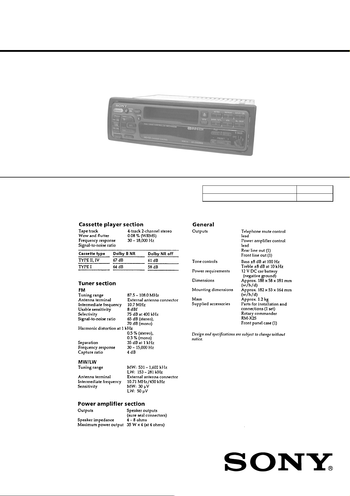
SPECIFICATIONS
Model Name Using Similar Mechanism NEW
T ape Transport Mechanism T ype
MG-25B-136
FM/MW/LW CASSETTE CAR STEREO
9-925-544-12 Sony Corporation
2001F0500-1 e Vehicle Company
C 2001.6 Shinagawa Tec Service Manual Production Group

TABLE OF CONTENTS
SERVICING NOTES
1. GENERAL
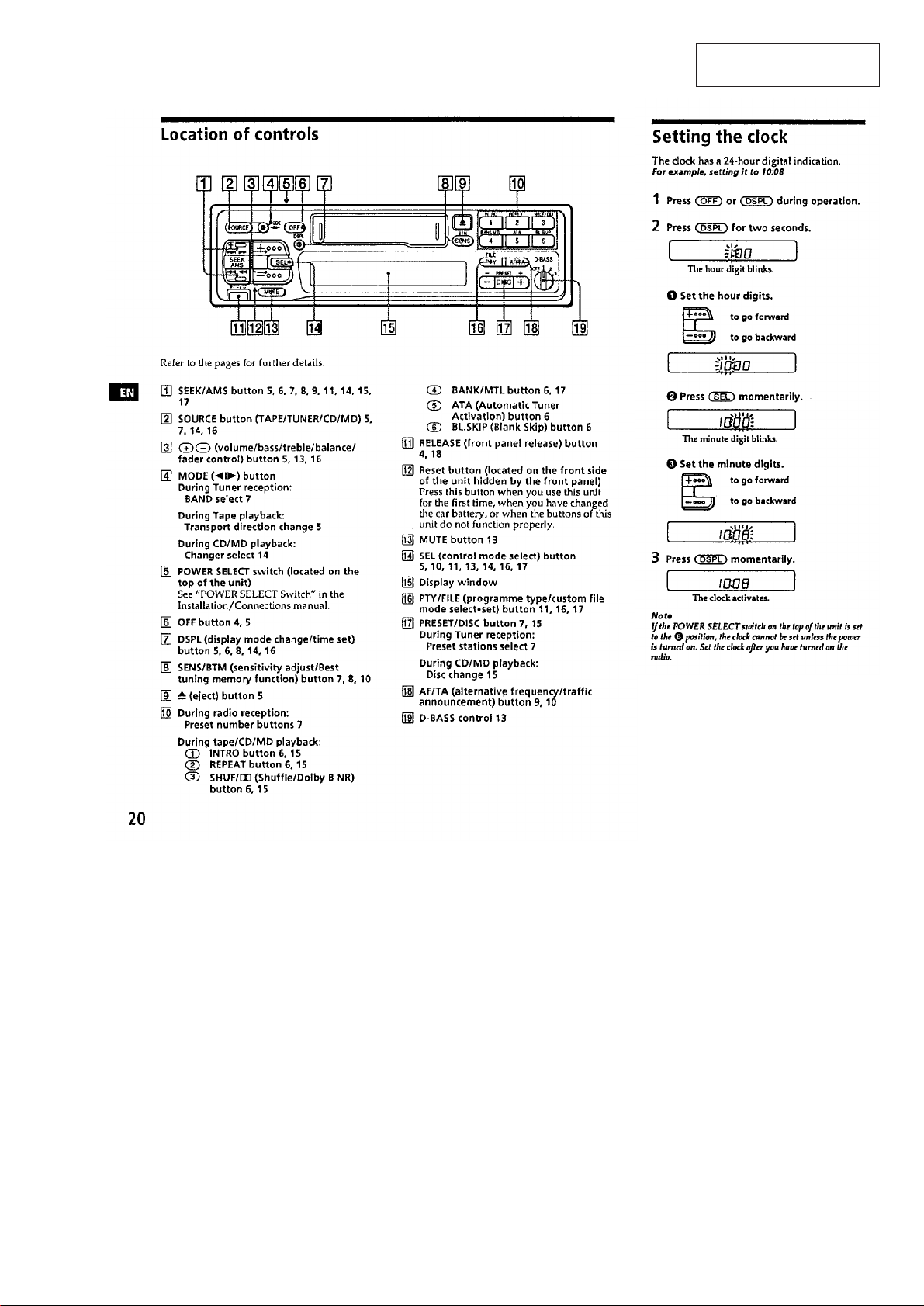
Location of Controls ........................................................ 3
Setting the Clock ............................................................. 3
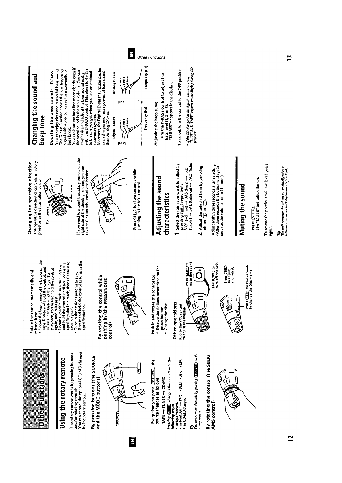
Using the Rotary Remote ................................................ 4
Adjusting the Sound Characteristics ............................... 4
Muting the Sound ............................................................ 4
Changing the Sound and Beep Tone................................ 4
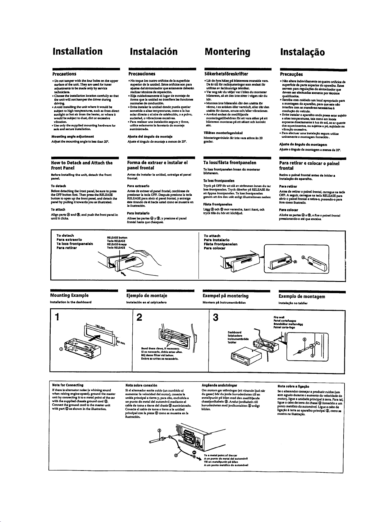
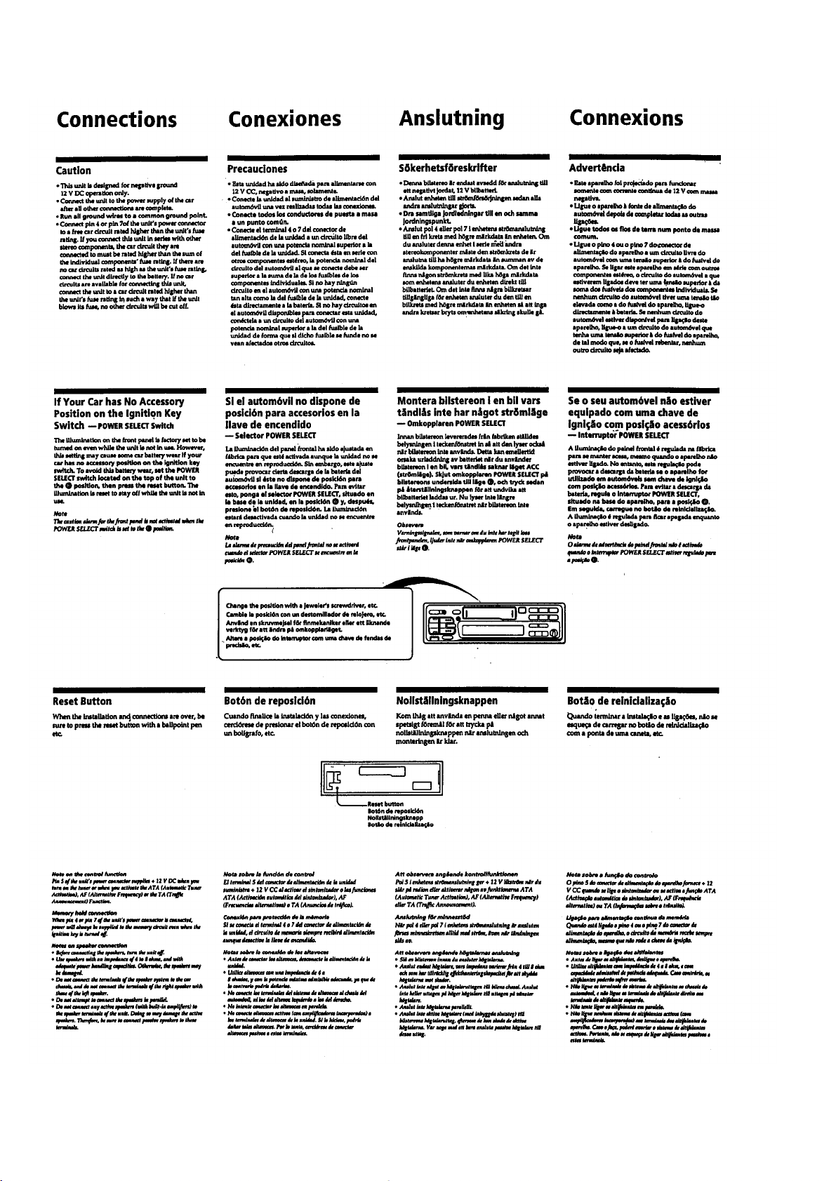
Installation ....................................................................... 5
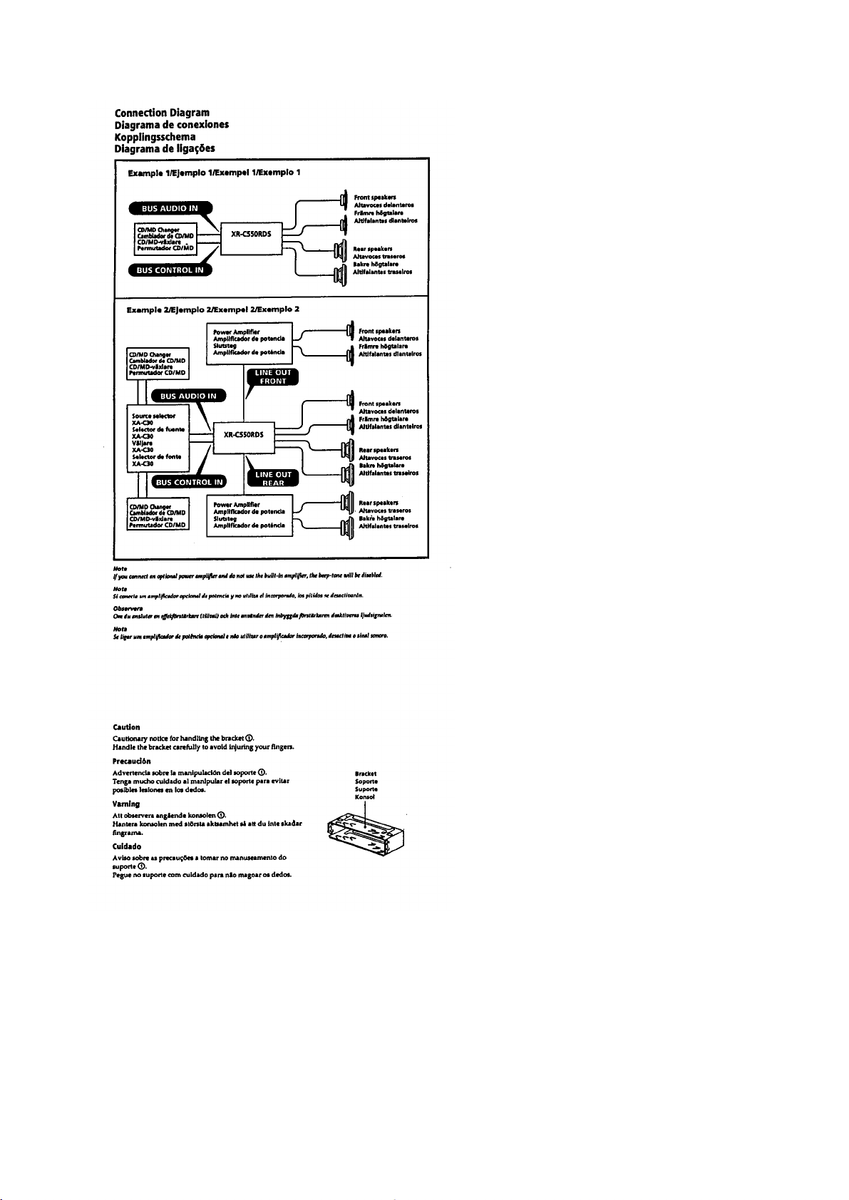
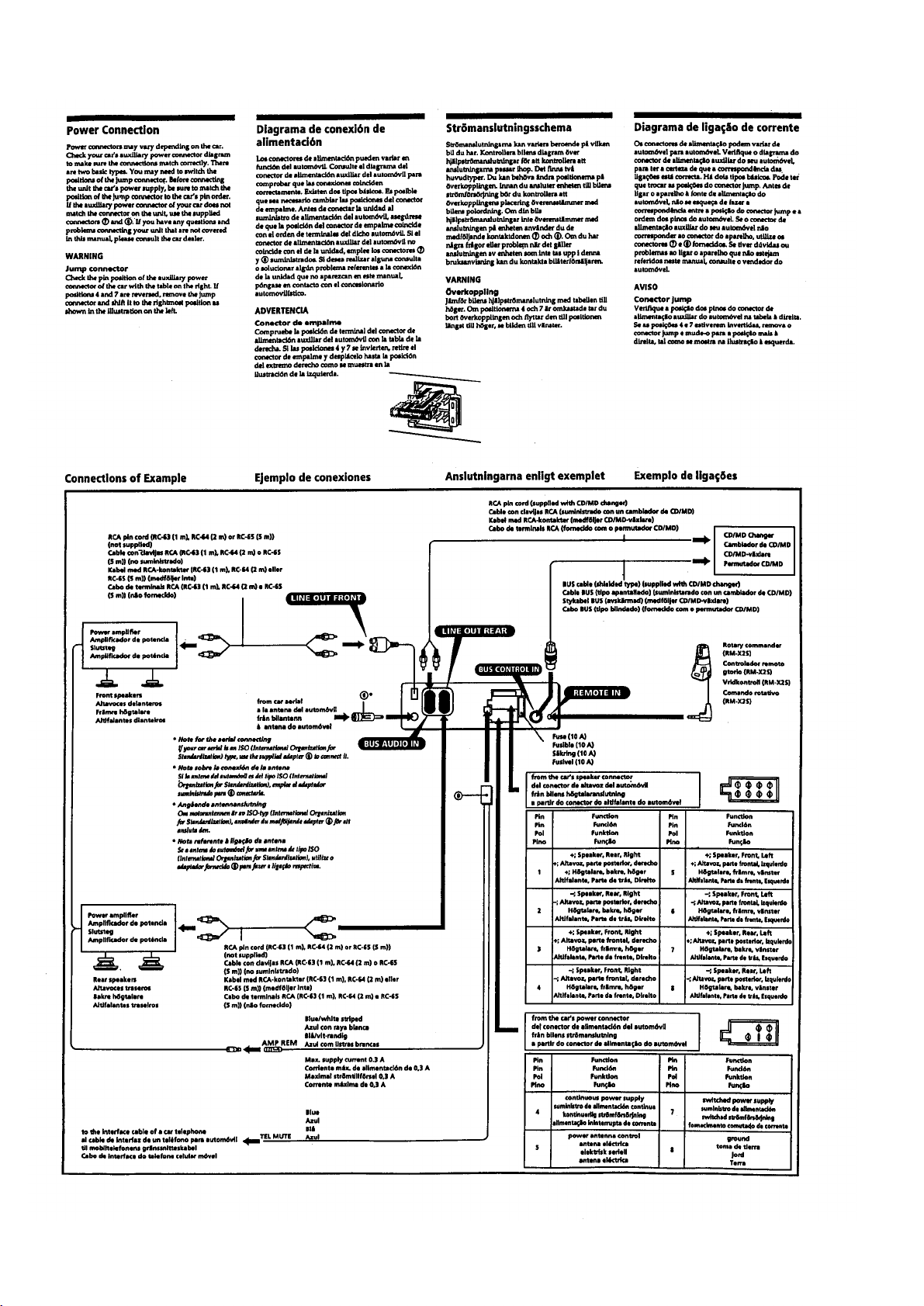
Connections ..................................................................... 6
2. DISASSEMBLY.......................................................... 9
3. ASSEMBLY OF MECHANISM DECK ........... 11
4. MECHANICAL ADJUSTMENTS ....................... 14
5. ELECTRICAL ADJUSTMENTS
Test Mode ........................................................................ 14
Tape Deck Section ........................................................... 15
Tuner Section................................................................... 15
6. DIAGRAMS
6-1. Printed Wiring Boards – Main Section –........................ 22
6-2. Schematic Diagram – Main Section – ............................. 25
6-3. Printed Wiring Board – Display Section – ..................... 30
6-4. Schematic Diagram – Display Section – ........................ 32
6-5. IC Pin Function Description ............................................ 35
Flexible Circuit Board Repairing
• Keep the temperature of the soldering iron around 270 ˚C dur-
ing repairing.
• Do not touch the soldering iron on the same conductor of the
circuit board (within 3 times).
• Be careful not to apply force on the conductor when soldering
or unsoldering
Notes on chip component replacement
• Never reuse a disconnected chip component.
• Notice that the minus side of a tantalum capacitor may be dam-
aged by heat.
7. EXPLODED VIEWS ................................................ 37
8. ELECTRICAL PARTS LIST................................ 40
– 2 –
SECTION 1
GENERAL
This section is extracted
from instruction manual.
– 3 –
– 4 –
– 5 –
– 6 –
– 7 –
– 8 –
SECTION 2
DISASSEMBLY
Note: Follow the disassembly procedure in the numerical order given.
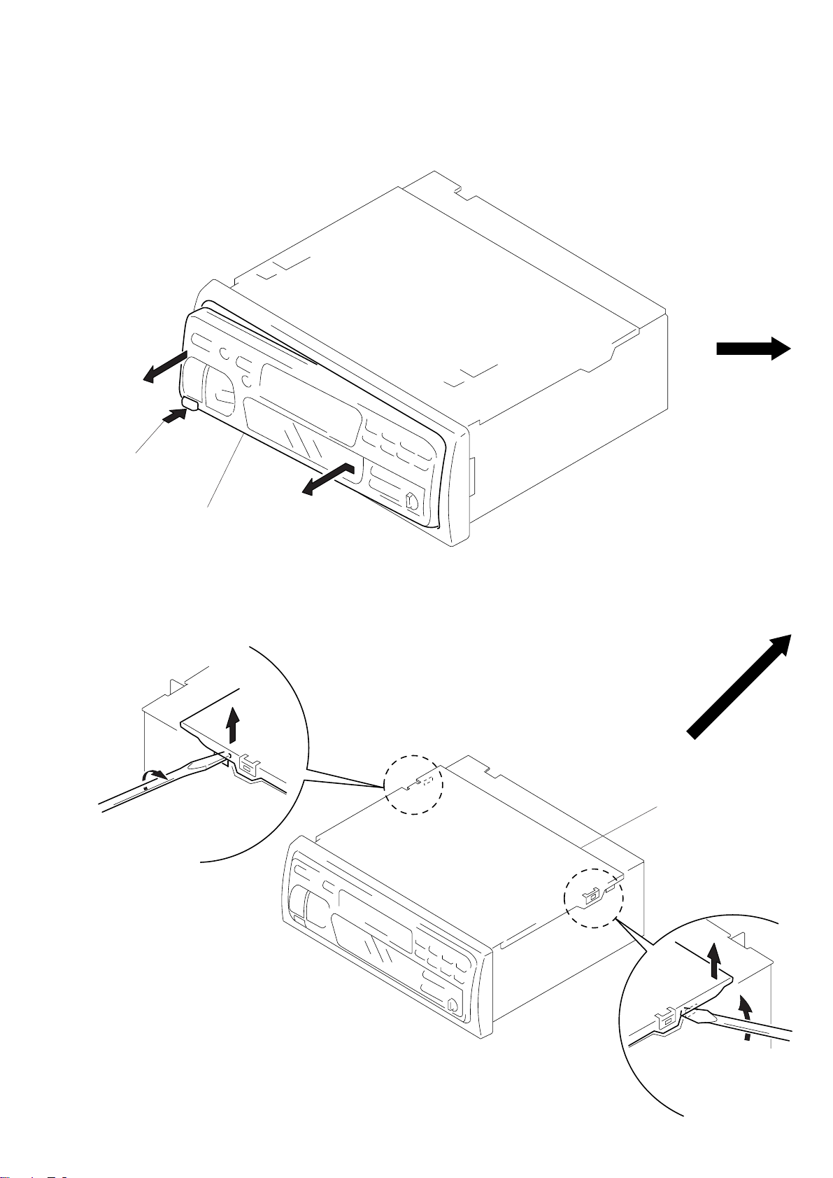
FRONT PANEL ASS’Y
1
Push the button
(release).
2
Remove the front panel ass’y
to the direction of the arrow A.
COVER ASS’Y
1
2
A
3
cover ass’y
– 9 –
2
1
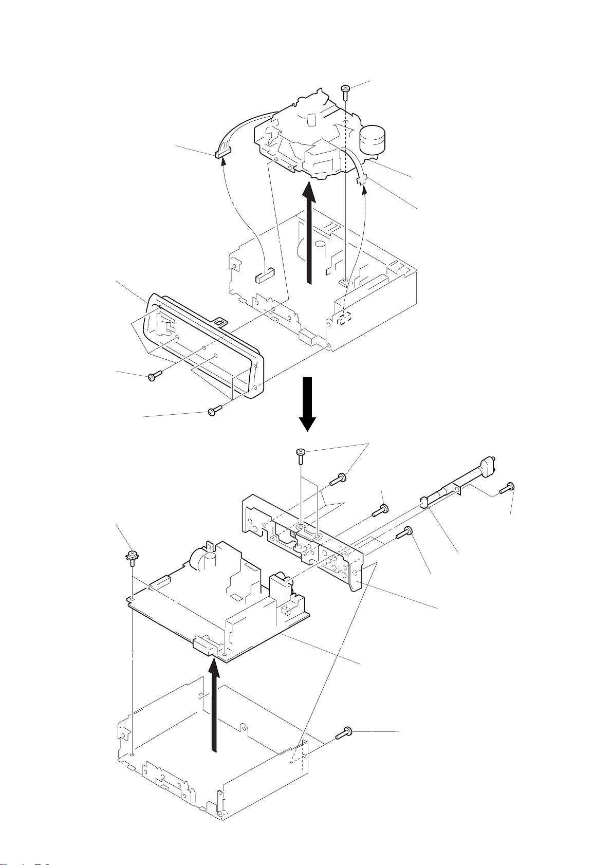
SUB PANEL, MECHANISM DECK (MG-25B-136)
3
connector
(CN302)
2
sub panel
1
three screws
(PTT2.6 × 8)
5
screw
(PTT2.6 × 6)
6
mechanism deck
(MG-25B-136)
4
flexible flat cable
(CN301)
1
three screws
(PTT2.6 × 8)
MAIN BOARD, HEAT SINK
4
two ground point
screws
6
five screws
(PTT2.6 × 8)
3
screw (PTT2.6 × 8)
5
main board
6
two screws
(PTT2.6 × 8)
7
heat sink
1
screw
(PTT2.6 × 8)
2
cord (with connector)
(line out front) (CN151)
– 10 –
3
two screws
(PTT2.6 × 8)
SECTION 3
ASSEMBLY OF MECHANISM DECK
Note: Follow the assembly procedure in the numerical order given.
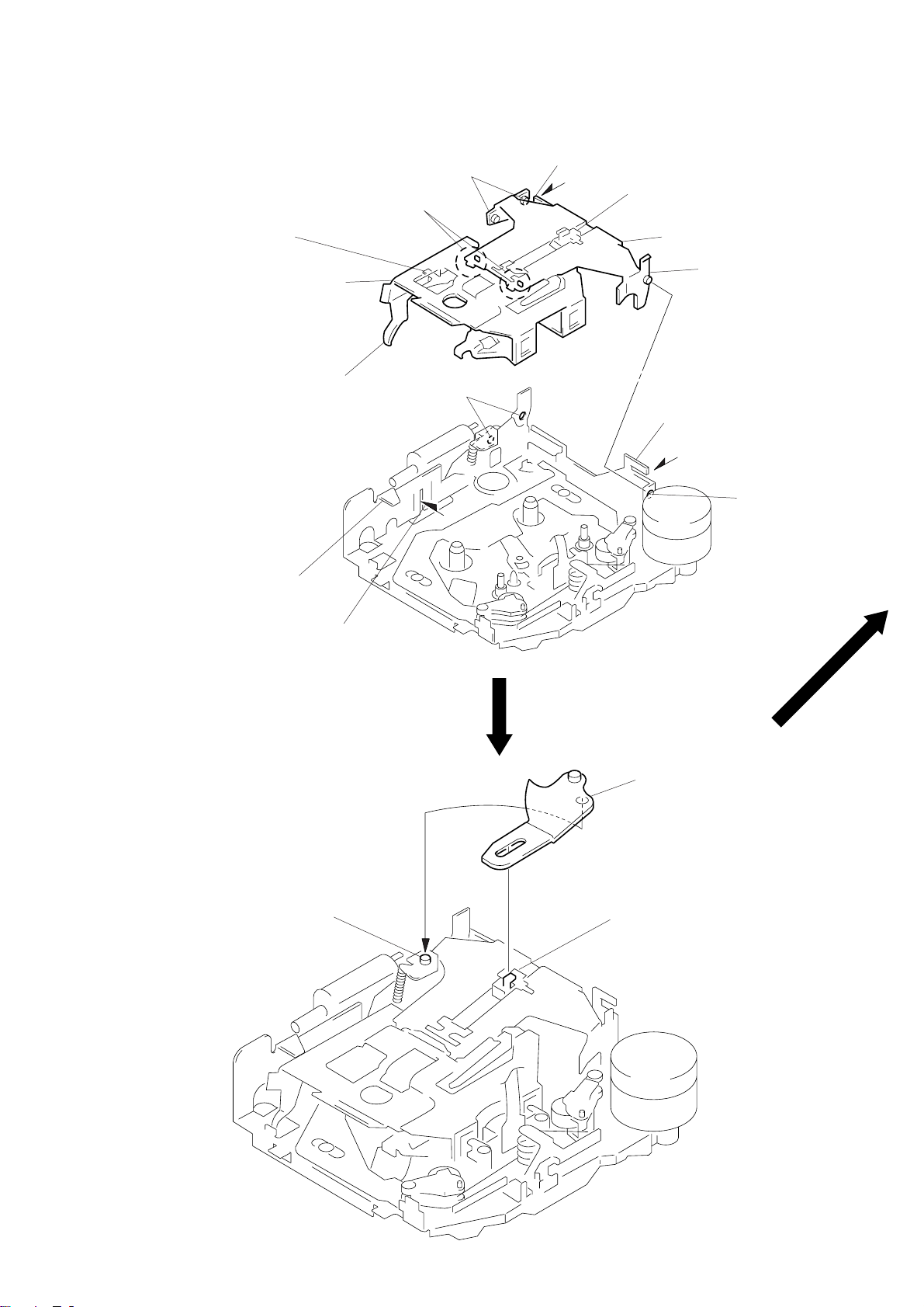
HOUSING
4
Fit claw on B part.
3
2
Install the hanger onto
two claws of the housing.
Put the housing
under A part.
housing
A
part
5
Fit projection on C part.
C
part
7
Hold the hanger by bending the claw.
1
Install the catch to the hanger.
hanger
6
Fit projection on D part.
8
Hold the hanger by
bending the claw.
D
part
ARM (SUCTION)
B
projection
part
2
Move the arm (suction) in the arrow
direction and fit on projection.
1
Fit the arm (suction) on the shaft.
– 11 –
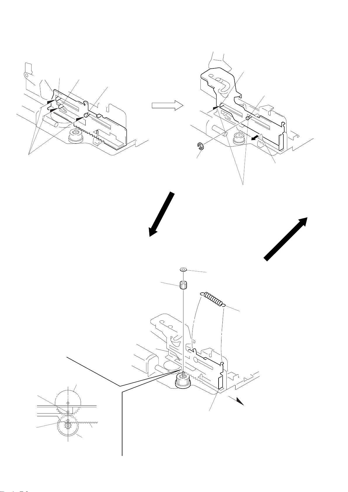
LEVER (LDG-A) / (LDG-B)
shaft
A
shaft
1
Fit the lever (LDG-A) on
shafts A – C and install it.
B
shaft
C
4
type-E stop ring 2.0
shaft
A
shaft
C
2
Pull the lever in the
arrow direction.
3
Fit the lever (LDG-B) on
shafts A and C and
install it.
GEAR (LDG-FT)
hole
hole
gear (LDG-D)
lever (LDG-A)
gear (LDG-FB)
4
gear (LDG-FT)
5
polyethylene washer
1
2
Move the lever (LDG-B)
in the arrow direction.
tension spring (lever LDG)
3
Align hole in the gear (LDG-D)
with hole in the lever (LDG-A).
– 12 –
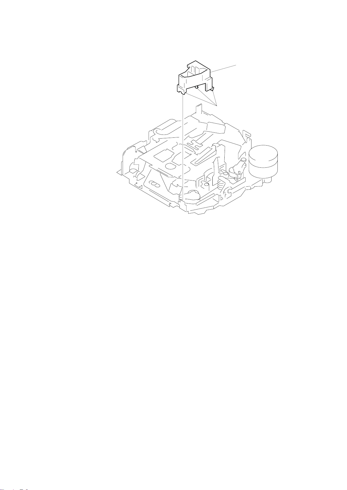
GUIDE (C)
1
three claws
2
guide (C)
– 13 –
SECTION 4
MECHANICAL ADJUSTMENTS
SECTION 5
ELECTRICAL ADJUSTMENTS
1. Clean the following parts with a denatured-alcohol-moistened
swab:
playback head pinch roller
rubber belt capstan
idlers
2. Demagnetize the playback head with a head demagnetizer.
3. Do not use a magnetized screwdriver for the adjustments.
4. After the adjustments, apply suitable locking compound to the
parts adjusted.
5. The adjustments should be performed with the power supply
voltage unless otherwise noted.
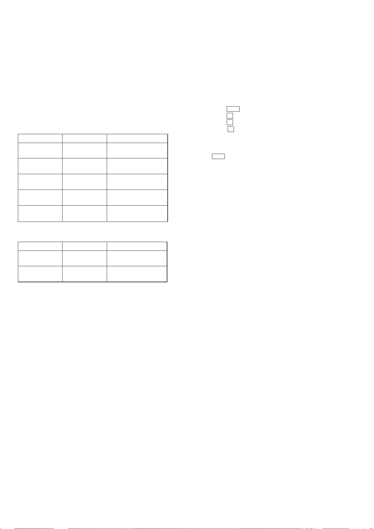
• T orque Measurement
Mode Torqu Meter Meter Reading
Forward CQ-102C
Forward
Back Tension (0.01 – 0.06 oz•inch)
Reverse CQ-102RC
Reverse
Back Tension (0.01 – 0.06 oz•inch)
FF, REW CQ-201B
CQ-102C
CA-102RC
30 – 65 g•cm
(0.42 – 0.90 oz•inch)
0.5 – 4.5 g•cm
30 – 65 g•cm
(0.42 – 0.90 oz•inch)
0.5 – 4.5 g•cm
60 – 200 g•cm
(0.83 – 2.78 oz•inch)
TEST MODE
This set have the test mode function. In the test mode, FM Auto
Scan/Stop Level and AM (MW) Auto Scan/Stop Level adjustments
can be performed easier than it in ordinary procedure.
<Set the Test Mode>
1. Set the “power select” switch (S801) is “A” position.
2. Turn ON the regulated power supply. (All LEDs on the set
lights up, and the clock is displayed.)
Note:Press the OFF button, if the clock is not displayed.
3. Push the preset 4 button.
4. Push the preset 5 button.
5. Press the preset 1 button for more than two seconds.
6. Then the display indicates all lights, the test mode is set.
<Release the Test mode>
1. Push the OFF button.
2. Set the power select switch (S801) is “B” position.
• T ape Tension Measurement
Mode Tension Meter Meter Reading
Forward CQ-403A
Reverse CQ-403R
more than 90 g
(more than 3.18 oz)
more than 90 g
(more than 3.18 oz)
– 14 –
FM
INTRO
REG
INTRO
REG
FM
INTRO
REG
See the adjustment location from on page 18 for the
r
r
adjustment.
0 dB=0.775 VTAPE DECK SECTION
Tape Speed Adjustment
Procedure:
1. Put the set into the FWD PB mode.
speed checker
or
test tape
WS-48A
(3 kHz, 0 dB)
set
speaker out terminal
frequency counte
4
Ω
+–
Specification: Constant speed
Speed checker Frequency counter
–1.5 to +2.5% 2,955 to 3,075 Hz
Adjustment Location: See page 18.
Dolby Level Adjustment
Setting:
Preset 3 (PLAY MODE) button: NR OFF
SEL (BAS) button : Center
SEL (TRE) button : Center
SEL (BAL) button : Center
SEL (FAD) button : Center
SEL (VOL) button : Maximum
D-BASS control : OFF
TUNER SECTION
0dB=1µV
Cautions during repair
When the tuner unit is defective, replace it by a new one because its internal block is difficult to repair.
[Note]
Adjust the tuner section in the sequence shown below.
1. FM Auto Scan/Stop Level Adjustment
2. FM Stereo Separation Adjustment
3. FM Noise Focus Adjustment
4. FM Signal Meter Adjustment
5. AM (MW) Auto Scan/Stop Level Adjustment
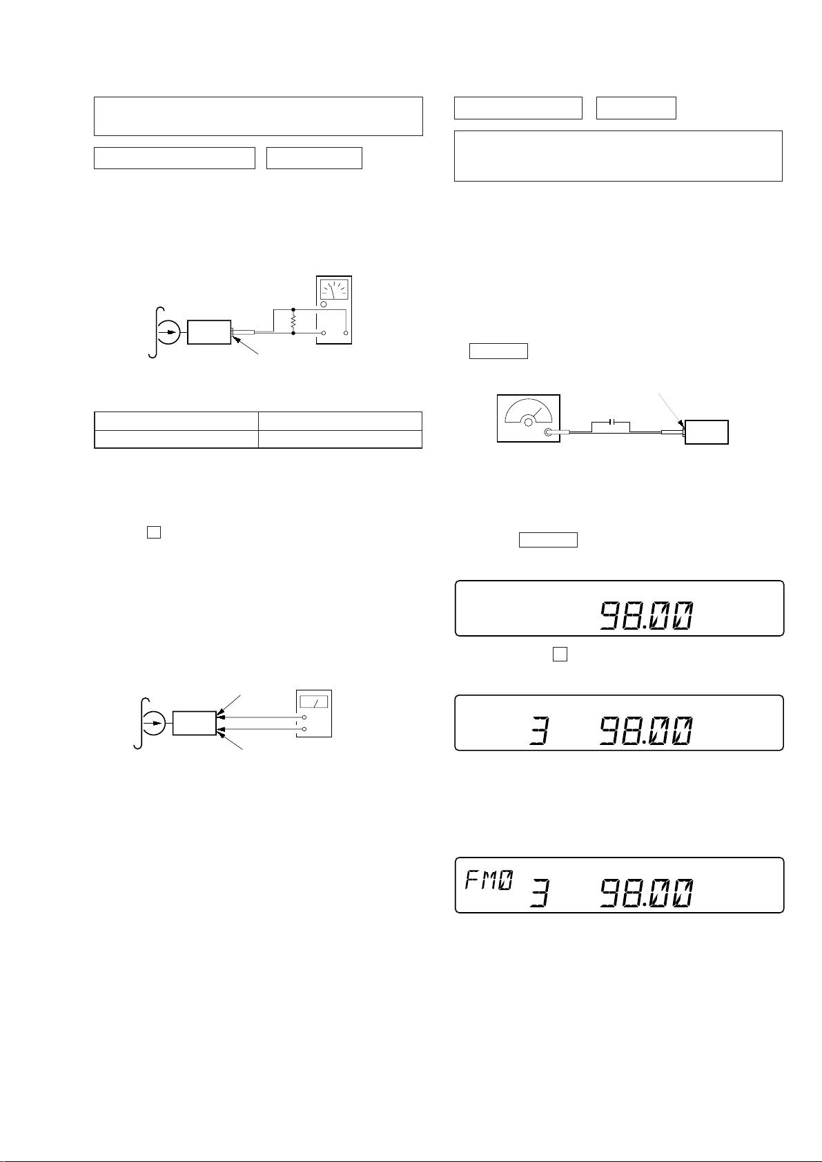
FM Auto Scan/Stop Level Adjustment
Setting:
SOURCE button: FM
FM RF signal
generator
Carrier frequency : 98.0 MHz
Output level : 22 dB (12.6
Mode : mono
Modulation : 1 kHz, 22.5 kHz deviation (30%)
antenna jack (J1)
0.01 µF
set
µ
V)
Procedure:
1. Set to the test mode. (See page 14).
2. Push the SOURCE button and set to FM.
Display
test tape
P-4-D400
(400Hz, 0dB)
main board
TP (DOLBY L)/
TP (DOLBY R)
set
level mete
main board
TP (GND)
+
–
Procedure:
1. Put the set into the FWD PB mode.
2. Adjust RV401 (L-CH) and RV301 (R-CH) so that the level
meter reading is –6±1 dBs (0.35 to 0.43 V).
Adjustment Location: See page 18.
3. Push the preset 3 button.
Display
4. Adjust with the volume RV2 on TU1 so that the “FM” indication turns to “FM0” indication on the display window.
But, in case of already indicated “FM0”, turn the RV2 so that
put out light “0” indication and adjustment.
Display
Adjustment Location: See page 18.
– 15 –
 Loading...