

Sony XRC-5090 Service manual
XR-C5090
SERVICE MANUAL
Refer to RM-X4S SERVICE MANUAL (9-925-698-∏) issued
previously for information of remote commander (RM-X4S)
supplied with this set
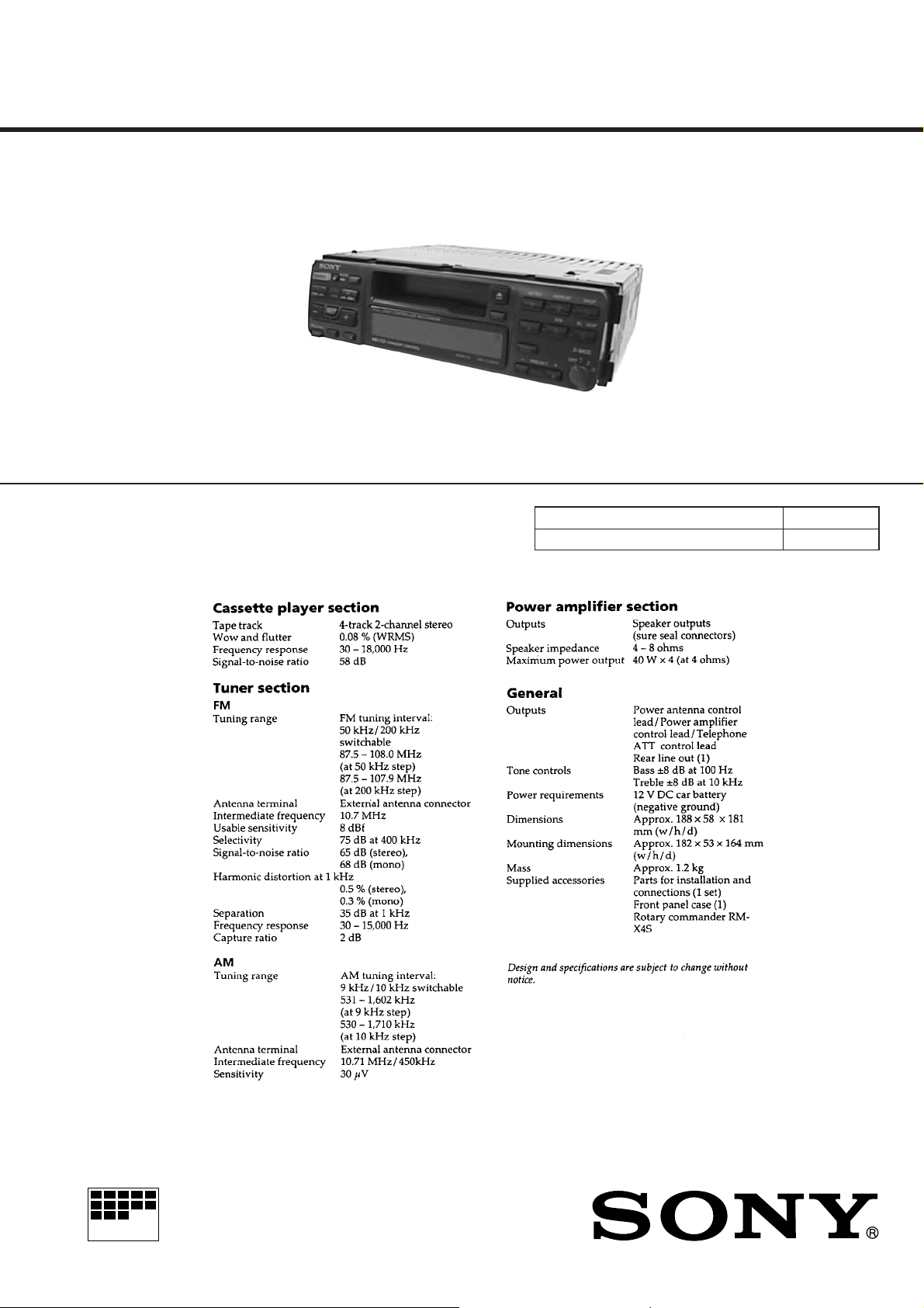
SPECIFICA TIONS
E Model
Model Name Using Similar Mechanism XR-C340
Tape T ransport Mechanism T ype MG-25F-136
MICROFILM
FM/AM CASSETTE CAR STEREO

TABLE OF CONTENTS
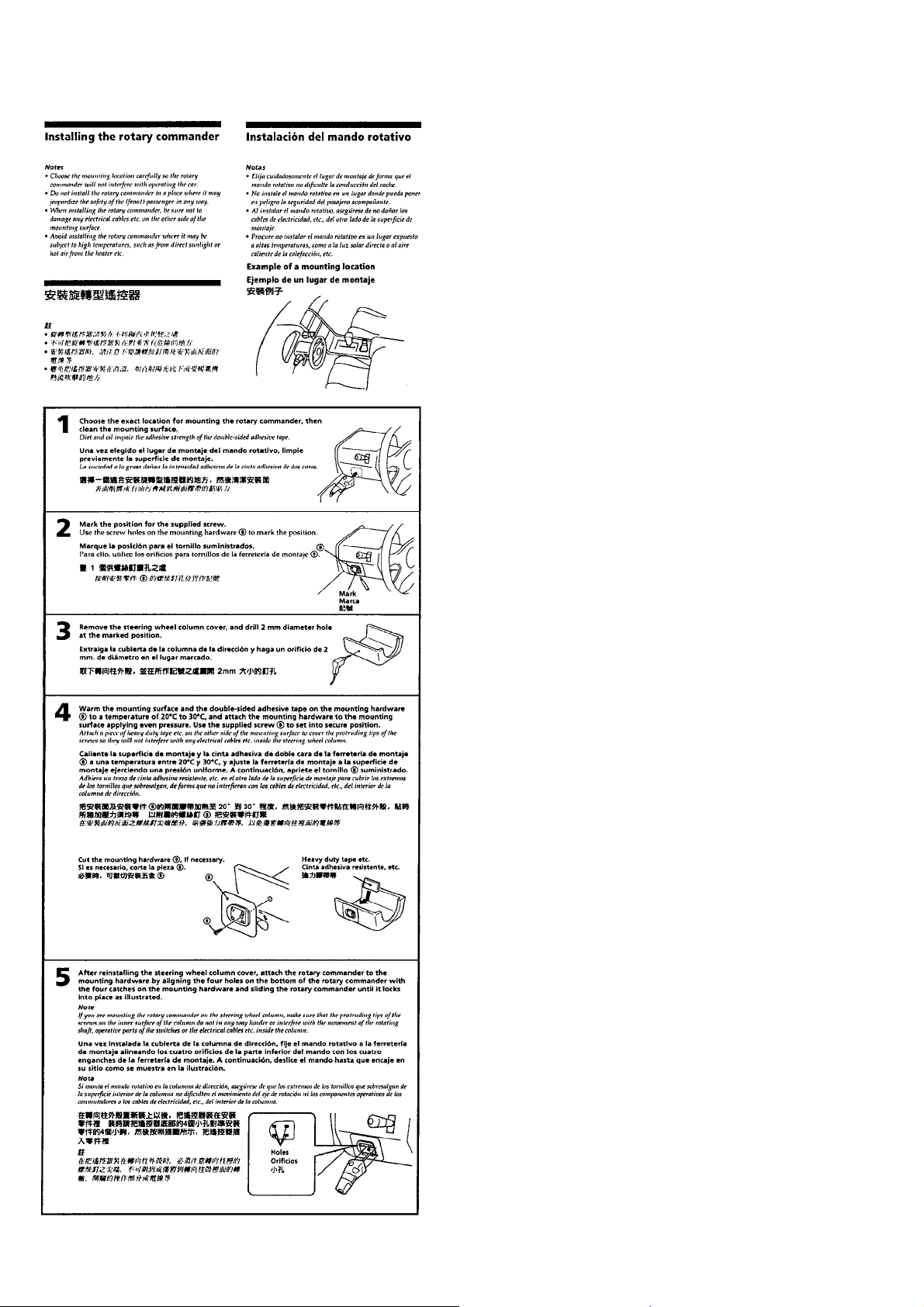
1. GENERAL
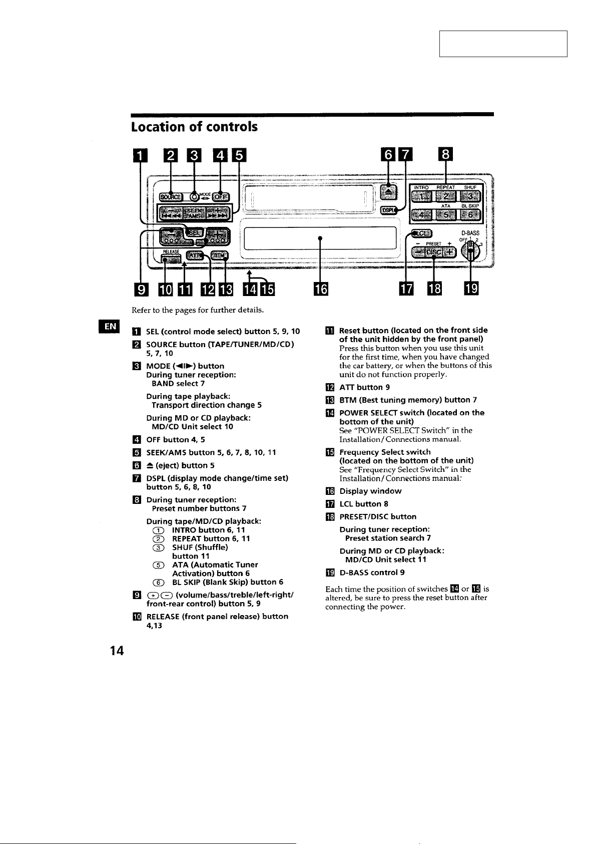
Location of Controls ....................................................... 3
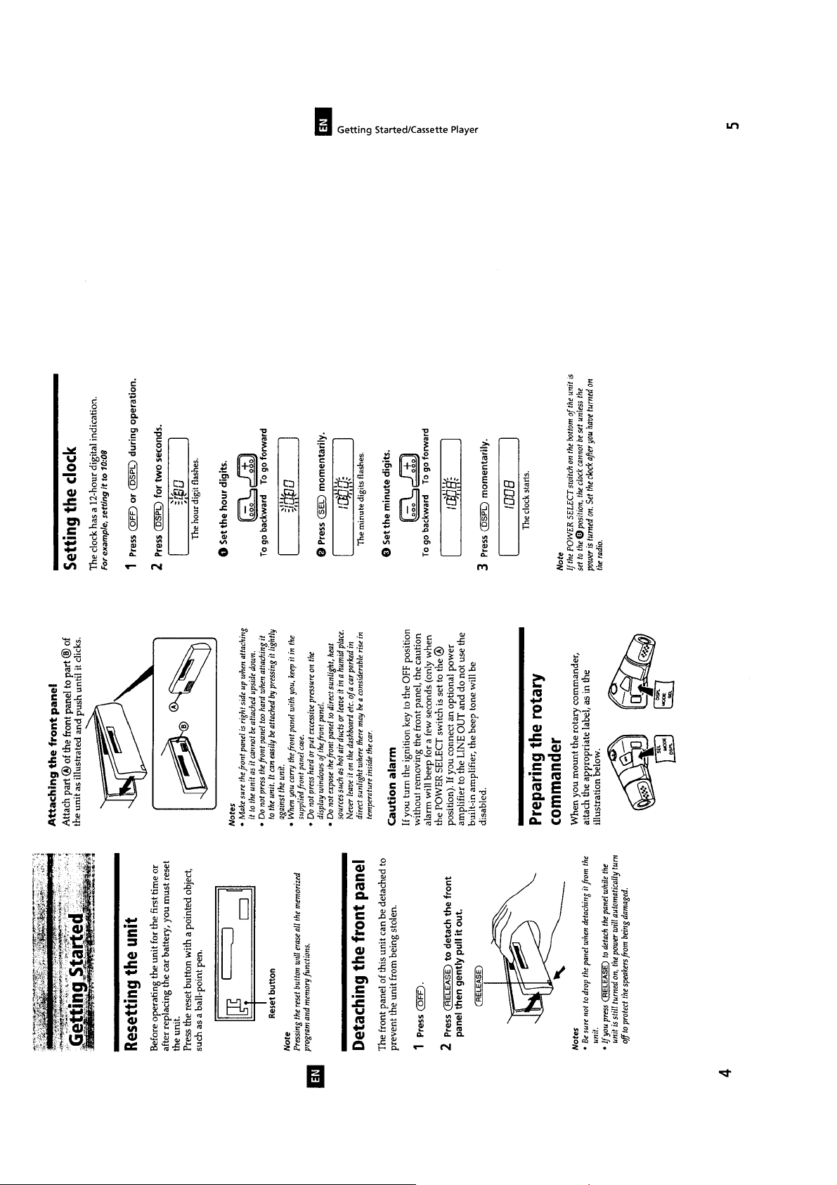
Setting the Unit ............................................................... 4
Detaching the Front Panel............................................... 4
Preparing the Rotary Commander .................................. 4
Setting the Clock ............................................................. 4
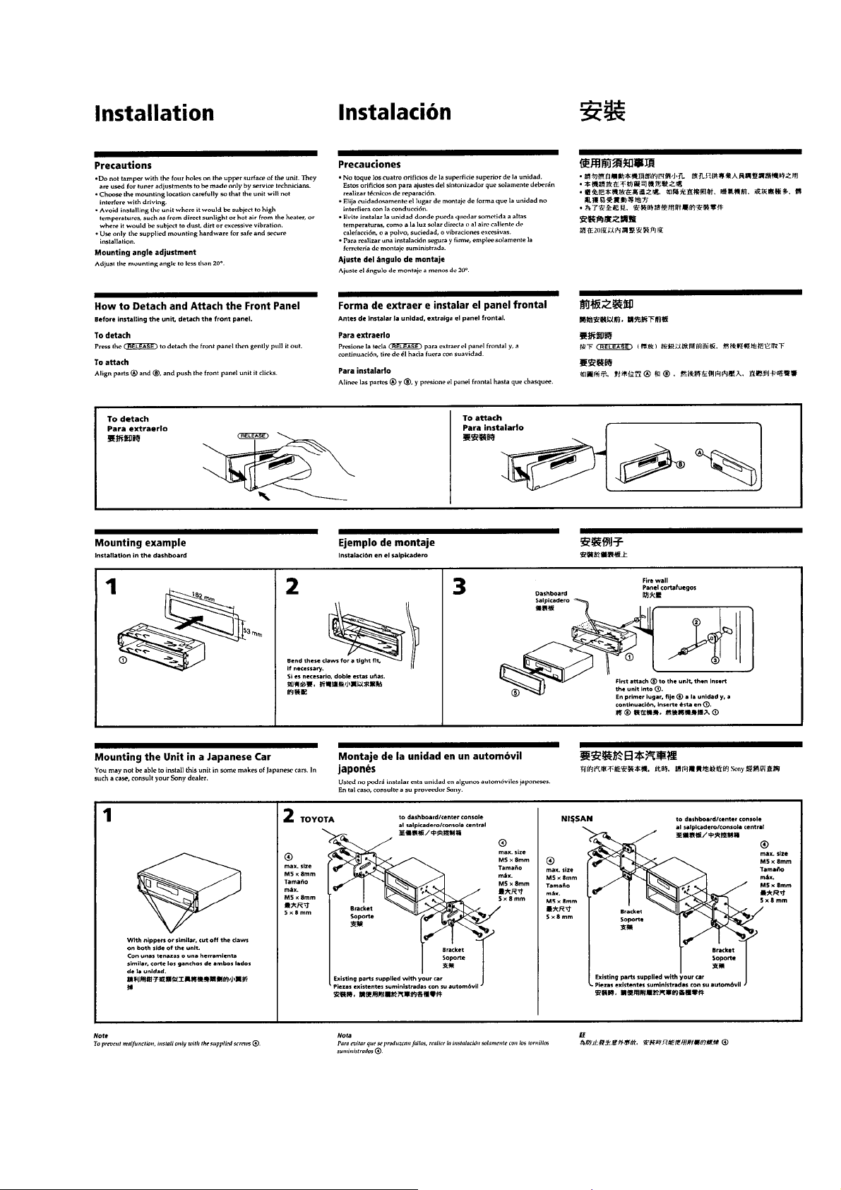
Installation....................................................................... 5
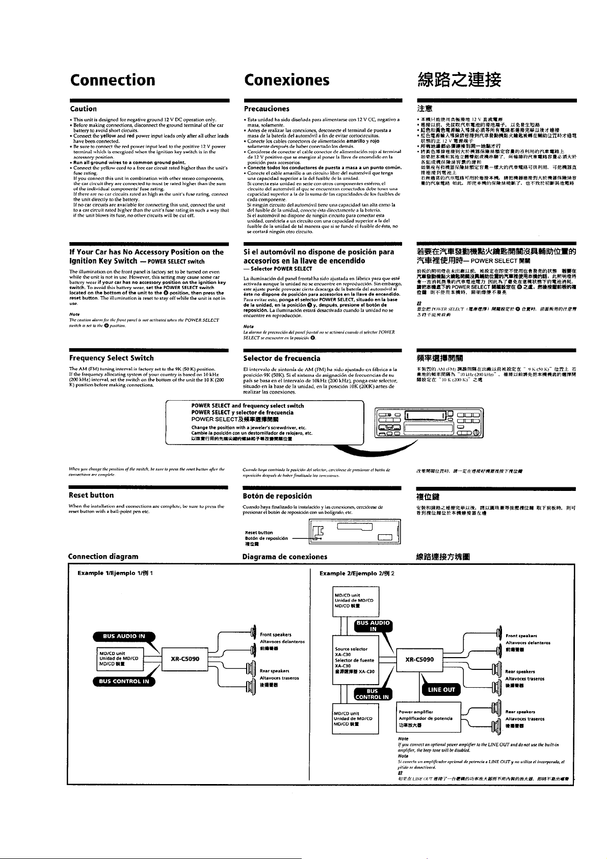
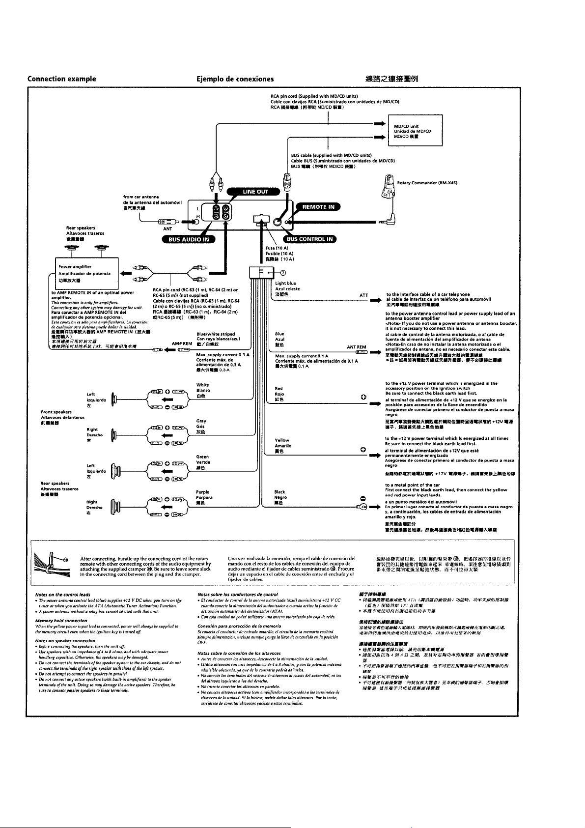
Connection ...................................................................... 7
2. DISASSEMBLY ......................................................... 9
3. ASSEMBLY OF MECHANISM DECK........... 11
4. MECHANICAL ADJUSTMENTS....................... 14
5. ELECTRICAL ADJUSTMENTS
Tape Deck Section .......................................................... 14
Tuner Section .................................................................. 14
6. DIAGRAMS
6-1. IC Pin Function Description ........................................... 15
6-2. Printed Wiring Boards – MAIN Section – .................... 19
6-3. Schematic Diagram – MAIN Section –.......................... 21
6-4. Printed Wiring Board – PANEL Section – .................... 25
6-5. Schematic Diagram – PANEL Section –....................... 27
7. EXPLODED VIEWS ................................................ 31
Flexible Circuit Board Repairing
• Keep the temperature of the soldering iron around 270 ˚C during repairing.
• Do not touch the soldering iron on the same conductor of the
circuit board (within 3 times).
• Be careful not to apply force on the conductor when soldering
or unsoldering.
Notes on chip component replacement
• Never reuse a disconnected chip component.
• Notice that the minus side of a tantalum capacitor may be damaged by heat.
8. ELECTRICAL PARTS LIST ............................... 34
– 2 –
SECTION 1
GENERAL
This section is extracted from
instruction manual.
– 3 –
– 4 –
– 5 –
– 6 –
– 7 –
– 8 –
SECTION 2
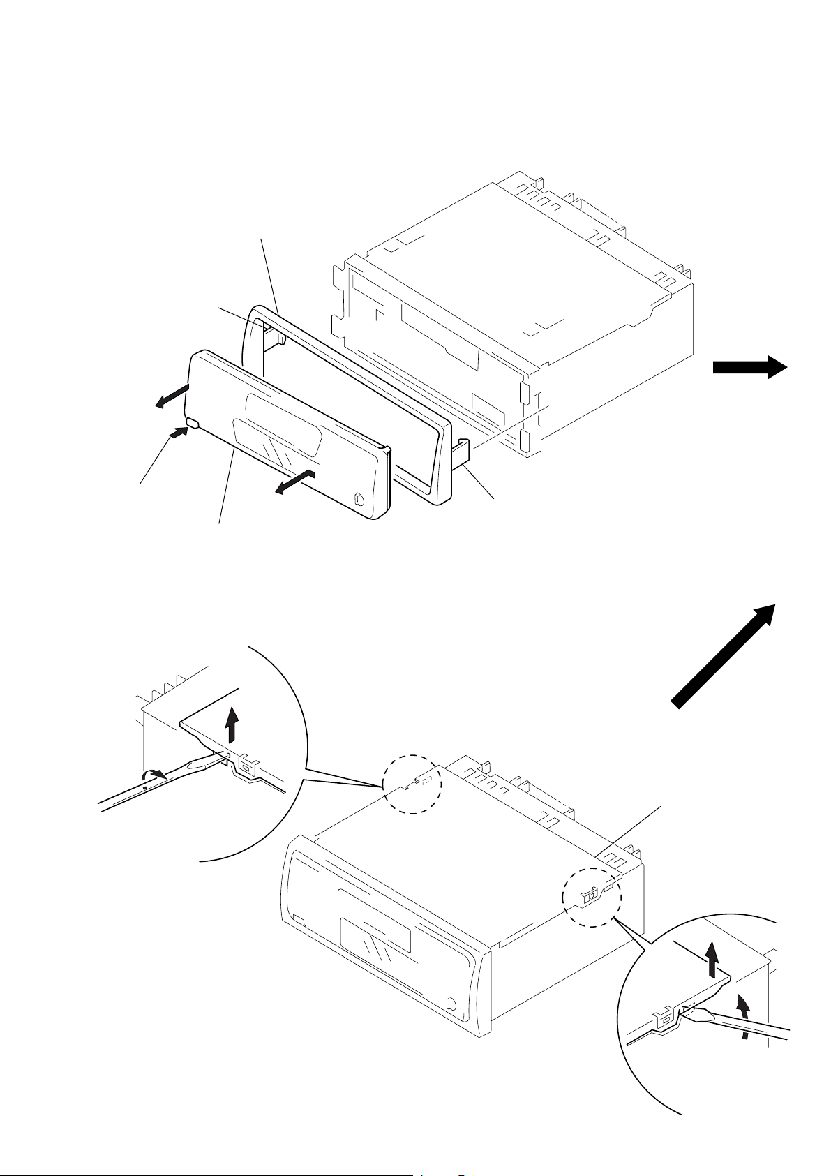
DISASSEMBLY
Note: Follow the disassembly procedure in the numerical order given.
FRONT PANEL ASS’Y, COLLAR
4
collar
3
claw
1
Push the button
(release).
2
COVER ASS’Y
1
A
Remove the front panel ass’y
to the direction of the arrow
2
A
3
claw
.
cover ass’y
3
– 9 –
2
1
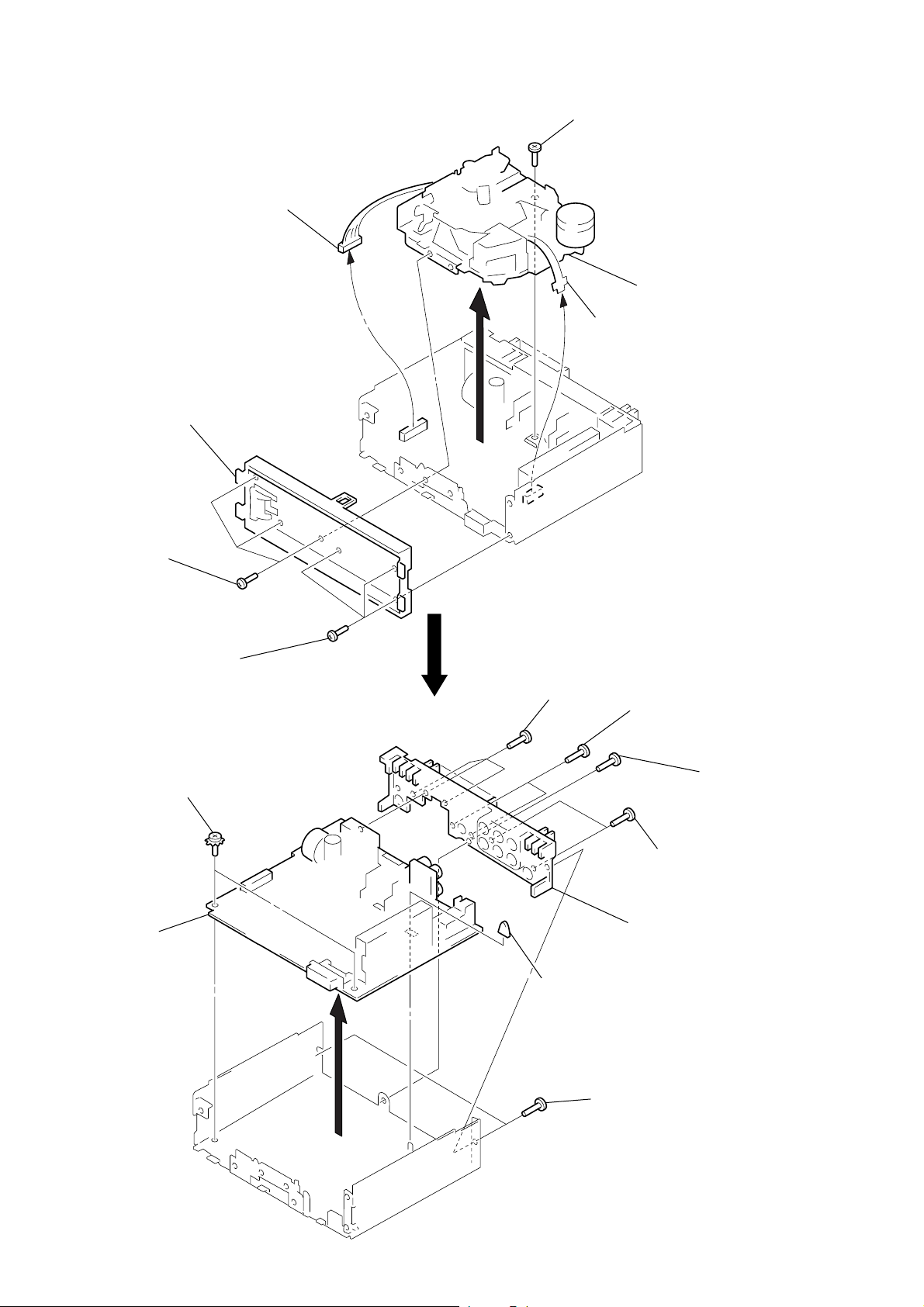
SUB PANEL, MECHANISM DECK (MG-25F-136)
k
3
connector
(CN351)
2
sub panel
1
three screws
(PTT2.6
×
8)
5
screw
(PTT2.6
4
flexible flat cable
(CN301)
×
6)
6
mechanism dec
(MG-25F-136)
1
three screws
(PTT2.6
×
8)
MAIN BOARD, HEAT SINK
3
two ground point
screws
4
main board
5
three screws
(PTT2.6
2
×
8)
rubber cap (25)
1
two screws
(PTT2.6
5
two screws
(PTT2.6
5
6
heat sink
×
×
10)
1
two screws
(PTT2.6
8)
screw
(PTT2.6
×
8)
×
8)
– 10 –
 Loading...