

Sony XR-C457 Installation Manual
Installation
3-860-018-11 (1)
Precautions
•Do not tamper with the four holes on the upper surface of the unit. They are used for tuner
adjustments to be made only by service technicians.
• Choose the installation location carefully so the unit will not hamper the driver during driving.
• Avoid installing the unit where it would be subject to high temperatures, such as from direct
sunlight or hot air from the heater, or where it would be subject to dust, dirt or excessive vibration.
• Use only the supplied mounting hardware for safe and secure installation.
Mounting angle adjustment
Adjust the mounting angle to less than 20°.
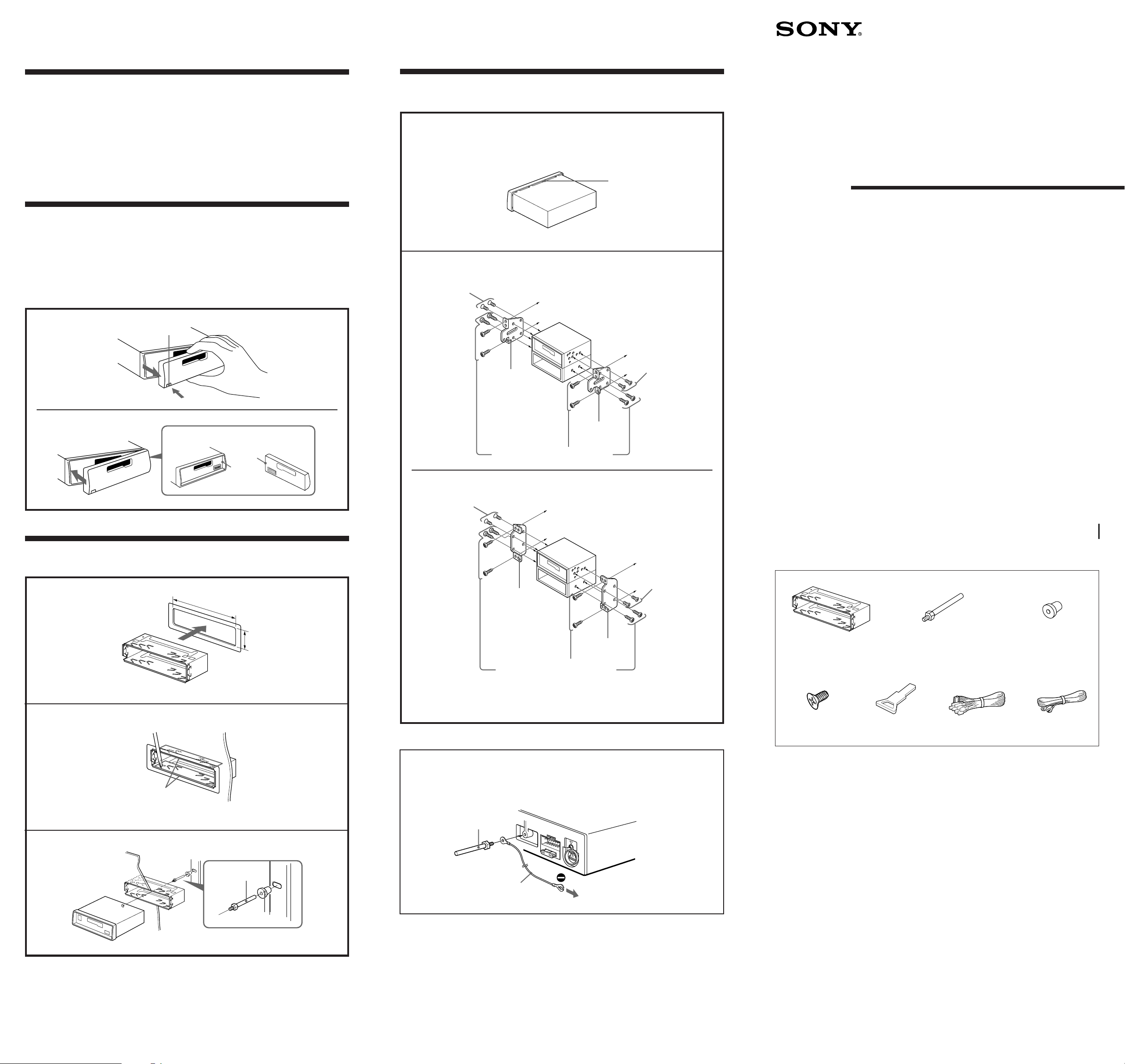
How to Detach and Attach the Front Panel
Before installing the unit, detach the front panel.
To detach
Press the RELEASE button to open up the front panel, then pull it out.
To attach
Align parts A and B, and push the front panel in until it clicks.
To detach
RELEASE button
Mounting the Unit in a Japanese Car
This unit may not be installed in some makes of cars. In this case, consult your nearest Sony dealer.
1 Run a blade along the slits on the back of the front trim and cut it
off of the unit.
Slit
2 TOYOTA
4*
max. size
M5 × 8mm
to dashboard/center console
FM/MW/SW
Cassette Car
Stereo
Installation/Connections
To attach
Mounting Example
Installation in the dashboard
1
182 mm
B
A
NISSAN
4*
max. size
M5 × 8mm
Bracket
Bracket
Existing parts supplied with your car
to dashboard/center console
Bracket
4*
max. size
M5 × 8mm
4*
max. size
M5 × 8mm
XR-C457
Sony Corporation 1997 Printed in Indonesia
Parts for Installation and Connections
The numbers in the list are keyed to those in the instructions.
1
2
3
2
3
1
Bend these claws, if necessary.
Dashboard
Fire wall
53 mm
2
Bracket
Existing parts supplied with your car
* To the prevent malfunction, install only with the
supplied screws 4. Do not use an electric or impact
screwdriver.
Note for Connecting
If there is alternator noise (a whining sound when raising engine speed), ground the master unit
by connecting it to a metal point of the car with the supplied chassis ground cord 7. Connect the
ground cord to the master unit with part 2 as shown in the illustration.
2
7
To a metal point of the car
× 1
4
× 5
(incl. 1 reserve) × 1 × 1
The release key 5 is used for dismounting the unit. See the Operating Instructions manual for details.
Caution
Cautionary notice for handling the bracket 1. Handle the bracket carefully to avoid injuring your
fingers.
5
× 1
× 1 × 1
6 7
3
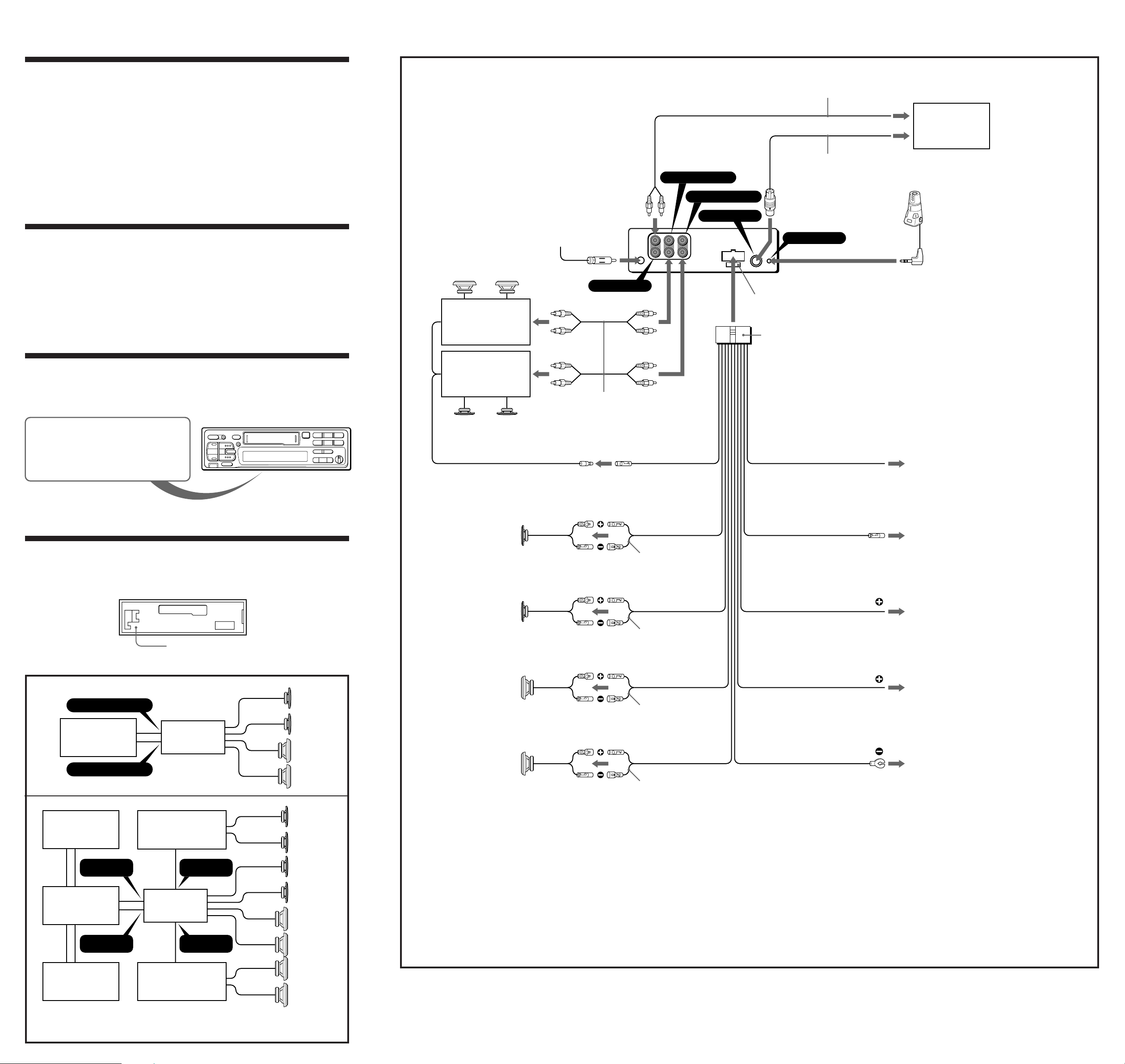
Connection
Caution
Connection example
• This unit is designed for negative ground 12 V DC operation only.
• Before making connections, disconnect the ground terminal of the car battery to avoid short circuits.
• Connect the yellow and red power input leads only after all other leads have been connected.
• Be sure to connect the red power input lead to the positive 12 V power terminal which is energized
when the ignition key is in the accessory position.
• Run all ground wires to a common ground point.
• Connect the yellow cord to a free car circuit rated higher than the unit’s fuse rating.
If you connect this unit in series with other stereo components, the car circuit they are connected to
must be rated higher than the sum of the individual component’s fuse rating.
If there are no car circuits rated as high as the unit’s fuse rating, connect the unit directly to the
battery.
If no car circuits are available for connecting this unit, connect the unit to a car circuit rated higher
than the unit’s fuse rating in such a way that if the unit blows its fuse, no other circuits will be cut off.
If your car has no accessory position on the ignition key switch
— POWER SELECT switch
The illumination on the front panel is factory set to be turned on even while the unit is not in use.
However, this setting may cause some car battery wear if your car has no accessory position on the
ignition key switch. To avoid this battery wear, set the POWER SELECT switch located on the
bottom of the unit to the B position, then press the reset button. The illumination is reset to stay
off while the unit is not in use.
Note
The caution alarm for the front panel is not activated when the POWER SELECT switch is set to the B position.
To AMP REMOTE IN of an optinal power amplifier.
This connection is only for amplifiers.
Connecting any other system may damage the unit.
from car antenna
Rear speakers
Power amplifier
ANT
BUS AUDIO IN
LINE OUT REAR
LINE OUT FRONT
BUS CONTROL IN
RCA pin cord (Supplied with CD/MD changers)
CD/MD changer
BUS cable (supplied with CD/MD changers)
Rotary remote RM-X2S (not supplied)
REMOTE IN
Fuse (10 A)
6
Frequency select switch
The MW (FM) tuning interval is factory-set to the 9K (50 K) position. If the frequency allocation
system of your country is based on 10 kHz (200 kHz) interval, set the switch on the bottom of the unit
to the 10 K (200 K) position before making connections.Connection
POWER SELECT and frequency select switch
Change the position with a jeweler’s screwdriver, etc.
When you change the position of the switch, be sure to press one of the reset button after the connections are complete.
Reset button
When the installation and connections are complete, be sure to press the reset button with a ballpoint
pen etc. The reset button is located on the left of the connector on the unit side when the front panel is
detached.
Front speakers
Power amplifier
Front speakers
Left
Right
RCA pin cord (RC-63 (1 m), RC-64 (2 m) or
RC-65 (5 m)) (not supplied)
AMP REM
Blue/white striped
Max. supply current 0.3 A
White striped
Gray striped
Light blue
Blue
Max. supply current 0.1 A
Red
TEL MUTE
ANT REM
to the interface cable of a car telephone
to the power antenna control lead or power supply lead of
antenna booster amplifier
<Note> In case of without power antenna, or antenna
booster, not necessary to connect this lead.
to the +12 V power terminal which is energized in the
accessory position on the ignition switch
Be sure to connect the black earth lead first.
Connection diagram
Example 1
BUS AUDIO IN
CD/MD changer
BUS CONTROL IN
Example 2
CD/MD changer
BUS AUDIO
IN
Source selector XA-C30
BUS
CONTROL IN
Reset button
XR-C457
Power amplifier
LINE OUT
FRONT
XR-C457
LINE OUT
REAR
Front speakers
Rear speakers
Front speakers
Front speakers
Rear speakers
Left
Green striped
Rear speakers
Right
Purple striped
Notes on the control leads
• The power antenna control lead (blue) supplies +12 V DC when you turn on the tuner or when you activate the ATA (Automatic
Tuner Activation) Function.
• A power antenna without a relay box cannot be used with this unit.
Memory hold connection
When the yellow power input lead is connected, power will always be supplied to the memory circuit even when the ignition switch is
turned off.
Notes on speaker connection
• Before connecting the speakers, turn the unit off.
• Use speakers with an impedance of 4 to 8 ohms, and with adequate power handling capacities. Otherwise, the speakers may be
damaged.
• Do not connect the terminals of the speaker system to the car chassis, and do not connect the terminals of the right speaker with
those of the left speaker.
• Do not attempt to connect the speakers in parallel.
• Do not connect any active speakers (with built-in amplifiers) to the speaker terminals of the unit. Doing so may damage the active
speakers. Therefore, be sure to connect passive speakers to these terminals.
Yellow
Black
to the +12 V power terminal which is energized at all times
Be sure to connect the black earth lead first.
to a metal point of the car
First connect the black earth lead, then connect the yellow
and red power input leads.
CD changer
If you connect and optional power amplifier and do not use the built-in amplifier, the beep-tone will be disabled.
For connecting two or more changers, the source selector XA-C30 (optional) and the BUS cable RC-61 (1 m) or RC-62 (2 m)
(optional) are necessary.
Power amplifier
Rear speakers
 Loading...