

Page 1

Multi Channel AV
Receiver
3-289-135-11(1)
Operating Instructions
STR-DG1200
©2008 Sony Corporation
Page 2
WARNING
To reduce the risk of fire or electric
shock, do not expose this apparatus to
rain or moisture.
To prevent fire, do not cover the ventilation of the
apparatus with newspapers, table-cloths, curtains,
etc. And don’t place lighted candles on the
apparatus.
To prevent fire or shock hazard, do not place objects
filled with liquids, such as vases, on the apparatus.
Do not install the appliance in a confined space, such
as a bookcase or built-in cabinet.
Install this system so that the power cord can be
unplugged from the wall socket immediately in the
event of trouble.
Batteries or batteries installed apparatus shall not be
exposed to excessive heat such as sunshine, fire or
the like.
For customers in the United
States
Owner’s Record
The model and serial numbers are located on the rear
of the unit. Record the serial number in the space
provided below. Refer to them whenever you call
upon your Sony dealer regarding this product.
M o d e l N o . ______________________________________________________
S e r i a l N o . ______________________________________________________
This symbol is intended to alert the
user to the presence of uninsulated
“dangerous voltage” within the
product’s enclosure that may be of
sufficient magnitude to constitute a
risk of electric shock to persons.
This symbol is intended to alert the
user to the presence of important
operating and maintenance
(servicing) instructions in the
literature accompanying the
appliance.
WARNING
This equipment has been tested and found to comply
with the limits for a Class B digital device, pursuant
to Part 15 of the FCC Rules. These limits are
designed to provide reasonable protection against
harmful interference in a residential installation.
This equipment generates, uses, and can radiate
radio frequency energy and, if not installed and used
in accordance with the instructions, may cause
harmful interference to radio communications.
However, there is no guarantee that interference will
not occur in a particular installation. If this
equipment does cause harmful interference to radio
or television reception, which can be determined by
turning the equipment off and on, the user is
encouraged to try to correct the interference by one
or more of the following measures:
– Reorient or relocate the receiving antenna.
– Increase the separation between the equipment
and receiver.
– Connect the equipment into an outlet on a circuit
different from that to which the receiver is
connected.
– Consult the dealer or an experienced radio/TV
technician for help.
US
2
Page 3

CAUTION
You are cautioned that any changes or modification
not expressly approved in this manual could void
your authority to operate this equipment.
Note to CATV system installer:
This reminder is provided to call CATV system
installer’s attention to Article 820-40 of the NEC
that provides guidelines for proper grounding and, in
particular, specifies that the cable ground shall be
connected to the grounding system of the building,
as close to the point of cable entry as practical.
About This Manual
• The instructions in this manual are for model
STR-DG1200. Check your model number by
looking at the lower right corner of the front panel.
• The instructions in this manual describe the
controls on the supplied remote. You can also use
the controls on the receiver if they have the same
or similar names as those on the remote.
• “Neural-THX” and “NEURAL-THX” introduced
in the Operating Instructions and displayed in the
display window and on the GUI menu screen mean
Neural-THX Surround.
This receiver incorporates Dolby* Digital and Pro
Logic Surround and the DTS** Digital Surround
System.
* Manufactured under license from Dolby
Laboratories.
Dolby, Pro Logic, Surround EX, and the doubleD symbol are trademarks of Dolby Laboratories.
** Manufactured under license under U.S. Patent
#’s: 5,451,942; 5,956,674; 5,974,380;
5,978,762; 6,226,616; 6,487,535 & other U.S.
and worldwide patents issued & pending. DTS is
a registered trademark and the DTS logos,
Symbol, DTS-HD and DTS-HD Master Audio
are trademarks of DTS, Inc. © 1996-2007 DTS,
Inc. All Rights Reserved.
This receiver incorporates High-Definition
Multimedia Interface (HDMI™) technology.
HDMI, the HDMI logo and High-Definition
Multimedia Interface are trademarks or registered
trademarks of HDMI Licensing LLC.
XM Ready
Satellite Radio Inc. All rights reserved.
© 2008 SIRIUS Satellite Radio Inc. “SIRIUS” and
the SIRIUS dog logo are registered trademarks of
SIRIUS Satellite Radio Inc.
®
is a registered trademark of XM
continued
3
US
Page 4

This product is manufactured under license from
Neural Audio Corporation and THX Ltd. Sony
Corporation hereby grants the user a non-exclusive,
non-transferable, limited right of use to this product
under USA and foreign patent, patent pending and
other technology or trademarks owned by Neural
Audio Corporation and THX Ltd. “Neural
Surround”, “Neural Audio”, “Neural” and “NRL”
are trademarks and logos owned by Neural Audio
Corporation, THX is a trademark of THX Ltd.,
which may be registered in some jurisdictions. All
rights reserved.
The font type (Shin Go R) installed in this receiver
is provided by MORISAWA & COMPANY LTD.
These names are the trademarks of MORISAWA &
COMPANY LTD., and the copyright of the font also
belongs to MORISAWA & COMPANY LTD.
iPod is a trademark of Apple Inc., registered in the
U.S. and other countries.
All other trademarks and registered trademarks are
of their respective holders. In this manual, ™ and ®
marks are not specified.
The Bluetooth word mark and logos are owned by
the Bluetooth SIG, Inc. and any use of such marks by
Sony Corporation is under license.
Other trademarks and trade names are those of their
respective owners.
“M-crew Server” is a trademark of Sony
Corporation.
“x.v.Color” and “x.v.Color” logo are trademarks of
Sony Corporation.
“BRAVIA” is a trademark of Sony Corporation.
US
4
Page 5

Table of Contents
Getting Started
Description and location of parts ................. 7
1: Installing the speakers ............................ 13
2: Connecting the speakers ........................ 15
3: Connecting the TV ................................. 17
4a: Connecting the audio components ....... 18
4b: Connecting the video components ....... 23
5: Connecting the antennas ........................ 33
6: Preparing the receiver and the remote .... 34
7: Operating the receiver using the GUI
(Graphical User Interface) .................... 36
8: Setting the speakers ................................ 39
9: Calibrating the appropriate speaker settings
automatically (Auto Calibration) .......... 41
Playback
Selecting a component ............................... 47
Listening to a Super Audio CD/CD ........... 49
Watching a DVD/Blu-ray Disc .................. 50
Enjoying video games ................................ 51
Watching video ........................................... 52
Amplifier Operations
Settings for the audio
(Audio settings menu) ........................... 53
Settings for the video
(Video settings menu) ........................... 54
Settings for HDMI
(HDMI settings menu) .......................... 54
Settings for the system
(System settings menu) ......................... 55
Enjoying Surround Sound
Enjoying a pre-programmed sound field .... 56
Resetting sound fields to the initial
settings ...................................................62
Enjoying the surround effect at low volume
levels (NIGHT MODE) .........................63
Advanced Speakers Set Up
Adjusting the speaker settings manually .... 63
Adjusting the equalizer ...............................68
Tuner Operations
Listening to FM/AM radio ......................... 69
Listening to satellite radio ..........................72
Control for HDMI
Using the Control for HDMI function for
“BRAVIA” Sync ....................................83
Preparing Control for HDMI function ........85
Watching a DVD (One-Touch Play) ...........86
Enjoying the TV sound from the speakers
connected to the receiver
(System Audio Control) ........................87
Turning off the receiver with the TV
(System Power Off) ............................... 88
continued
US
5
Page 6

Other Operations
Converting analog video input signals .......88
Enjoying the sound/images from the
components connected to the DIGITAL
MEDIA PORT .......................................89
Naming inputs ............................................ 92
Switching between digital and analog audio
(INPUT MODE) ....................................93
Enjoying the sound/images from other
inputs .....................................................94
Changing the display window ....................96
Using the sleep timer ................................100
Recording using the receiver ....................100
Using a bi-amplifier connection ...............102
Operating without connecting to the
TV ........................................................103
Using the Remote
Operating each component using the
remote ..................................................113
Programming the remote ..........................115
Performing several commands in sequence
automatically (Macro Play) .................119
Setting remote control codes that are not
stored in the remote .............................121
Clearing all the contents of the remote’s
memory ................................................ 122
Additional Information
Glossary ....................................................123
Precautions ............................................... 126
Troubleshooting ........................................127
Specifications ............................................ 132
Index ......................................................... 134
US
6
Page 7
Getting Started
Description and location of parts
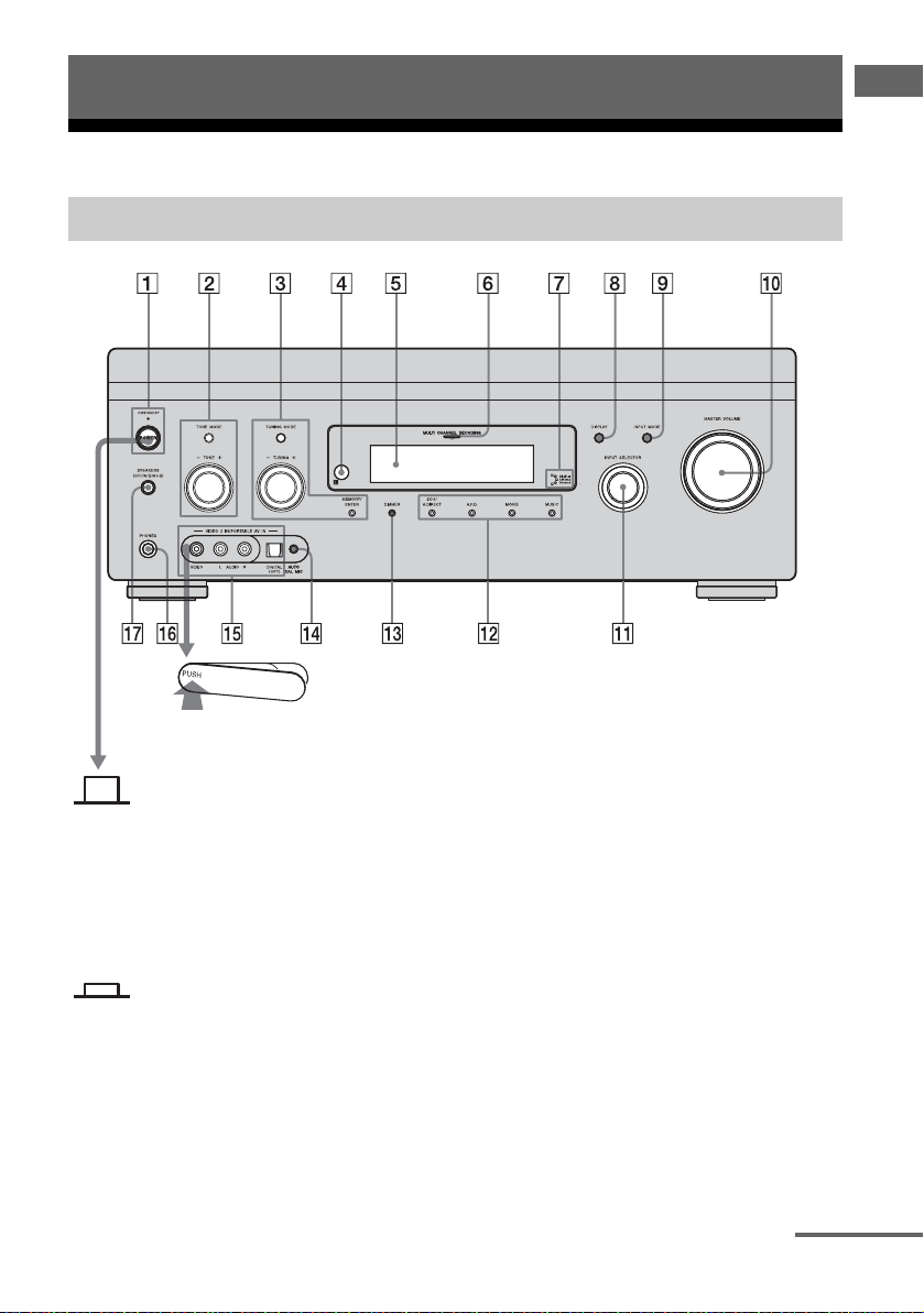
Front panel
To remove the cover
Press PUSH.
When you remove the cover, keep it out
of reach from children.
Getting Started
Status of the POWER button
Off
The receiver is turned off (the ON/
STANDBY lamp lights off) (initial
setting).
Press POWER to turn the receiver on.
You cannot turn the receiver on using
the remote.
On/Standby
Press ?/1 on the remote to
- turn the receiver on (the ON/
STANDBY lamp lights up in green).
- set the receiver to standby mode (the
ON/STANDBY lamp lights up in red).
When you press POWER on the
receiver, the receiver will be turned off.
continued
US
7
Page 8

Name Function
A POWER Press to turn the
receiver on or off.
ON/STANDBY
lamp
Shows the status of the
receiver.
B TONE MODE Adjust the bass and
TONE +/–
treble for the front,
center and surround/
surround back
channels. Press TONE
MODE repeatedly to
select the item you
want, then turn TONE
+/– to adjust the level
(page 106).
C TUNING MODE Press to operate a tuner
TUNING +/–
MEMORY/
ENTER
(FM/AM) and satellite
radio (XM/SIRIUS)
(page 110).
D Remote sensor Receives signals from
remote commander.
E Display
window
The current status of
the selected component
or a list of selectable
items appears here
(page 97).
F MULTI
CHANNEL
DECODING
Lights up when multi
channel audio signals
are decoded.
lamp
G Digital Cinema
Sound lamp
Lights up when a sound
field with DCS
mark is selected
(page 61).
H DISPLAY Press repeatedly to
select information
displayed on the
display window.
Name Function
I INPUT MODE Press to select the input
mode when the same
components are
connected to both
digital and analog jacks
(page 93).
J MASTER
VOLUME
Turn to adjust the
volume level of all
speakers at the same
time.
K INPUT
SELECTOR
Turn to select the input
source to play back.
L 2CH/A.DIRECT Press to select a sound
field (page 57) or to
switch the audio of the
selected input to analog
signal without any
adjustment (page 110).
A.F.D.
MOVIE
MUSIC
Press to select a sound
field (page 59).
M DIMMER Press repeatedly to
adjust the brightness of
the display window.
N AUTO CAL MIC
jack
Connects to the
supplied optimizer
microphone for the
Digital Cinema Auto
Calibration function
(page 42).
O VIDEO 2 IN/
PORTABLE AV
IN jacks
Connect to a portable
audio/video component
such as a camcorder or
video game.
P PHONES jack Connects to
headphones.
Q SPEAKERS
(OFF/A/B/A+B)
Press to select the
speaker system
(page 40).
US
8
Page 9
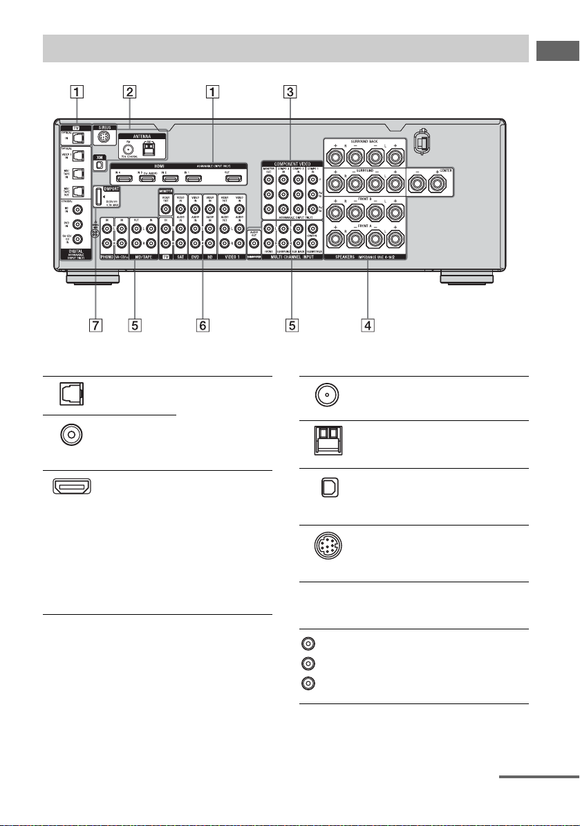
Rear panel
Getting Started
A DIGITAL INPUT/OUTPUT section
OPTICAL IN/
OUT jacks
COAXIAL IN
jacks
HDMI IN/
OUT* jacks
Connects to a DVD
player, Super Audio
CD player, etc. The
COAXIAL jack
provides a better
sound quality (page
17, 19, 26, 27).
Connects to a DVD
player, Blu-ray disc
player, satellite
tuner, etc. The image
is output to a TV or a
projector while the
sound can be output
from a TV or/and
speakers connected
to this receiver
(page 17, 24).
B ANTENNA section
FM ANTENNA
jack
AM
ANTENNA
jack
XM jack Connects to the XM
SIRIUS jack Connects to a
Connects to the
supplied FM wire
antenna (page 33).
Connects to the
supplied AM loop
antenna (page 33).
Mini-Tuner and
Home Dock (not
supplied) (page 73).
SiriusConnect Home
tuner (not supplied)
(page 73).
C COMPONENT VIDEO INPUT/
OUTPUT section
Green
(Y)
Blue
(P
B/CB)
Red
R/CR)
(P
Y, PB/CB, PR/
C
IN/OUT*
R
jacks
Connects to a DVD
player, TV, satellite
tuner, etc. (page 17,
26, 27, 28).
continued
US
9
Page 10
D SPEAKERS section
Connects to speakers
(page 15).
E AUDIO INPUT/OUTPUT section
White (L)
Red (R)
Black
AUDIO IN/
OUT jacks
MULTI
CHANNEL
INPUT jacks
AUDIO OUT
jack
Connects to a tape
deck or MD deck,
etc. (page 17, 19,
22).
Connects to a Super
Audio CD player or
DVD player with an
analog audio jack for
7.1 channel or 5.1
channel sound
(page 21).
Connects to a
subwoofer.
F VIDEO/AUDIO INPUT/OUTPUT
section
White (L)
Red (R)
Ye l l o w
AUDIO IN/
OUT jacks
VIDEO IN/
OUT* jacks
Connects to a VCR
or a DVD player, etc.
(page 17, 26, 27, 28,
29).
G DMPORT
Connects to a
DIGITAL MEDIA
PORT adapter
(page 19).
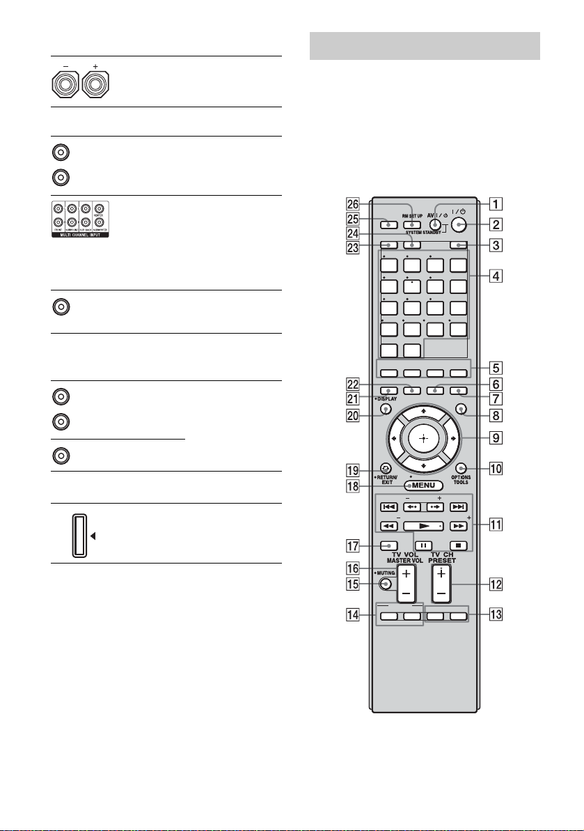
Remote commander
You can use the supplied RM-AAL019
Remote Commander to operate the receiver
and to control the Sony audio/video
components that the remote is assigned to
operate (page 115).
RM-AAL019
THEATER
THEATER
23
23
BD DVD
BD DVD
MD/
MD/
TV
TV
TAPE
TAPE
MULTI
MULTI
IN
IN
ENT/MEM
ENT/MEM
HOME
HOME
CATEGORY
CATEGORY
AMPTV
AMPTV
TV INPUT
TV INPUT
WIDE
WIDE
SA-CD/
SA-CD/
CD
CD
D.TUNING
D.TUNING
DMPORT
DMPORT
CLEAR
CLEAR
HDMI4
HDMI4
MUSICMOVIE
MUSICMOVIE
NIGHT
NIGHT
MODESLEEP
MODESLEEP
GUI
GUI
MODE
MODE
TUNING
TUNING
SHIFT
SHIFT
1
1
VIDEO2VIDEO1
VIDEO2VIDEO1
456
456
SAT
SAT
789
789
PHONO
TUNER
PHONO
TUNER
-/--
0/10
-/--
0/10
HDMI2HDMI1 HDMI3
HDMI2HDMI1 HDMI3
SIRIUS
SIRIUS
XM
XM
2CH/
2CH/
A.F.D.
A.DIRECT
A.F.D.
A.DIRECT
INPUT
INPUT
MODERESOLUTION
MODERESOLUTION
CATEGORY MODETUNING
CATEGORY MODETUNING
DISC SKIP
DISC SKIP
* You can watch the selected input image when you
connect the MONITOR OUT or HDMI OUT jack
to a TV (page 17). You can operate this receiver
using a GUI (Graphical User Interface) (page 36).
US
10
BD/DVD
BD/DVD
TOP MEN U
MENU
TOP MEN U
MENU
MACRO 1 MACRO 2
MACRO 1 MACRO 2
F1 F2
F1 F2
Page 11

Name Function
A AV ?/1 (on/
standby)
B ?/1 (on/
standby)
C AMP Press to light up the button to
D Input
buttons
b)
(TV
)
Numeric
buttons
(number 5
Press to turn on or off the audio/
video components that the
remote is assigned to operate
(page 115).
To turn the TV on or off, press
TV (X), then press AV ?/1.
If you press the ?/1 (B) at the
same time, it will turn off the
receiver and other Sony
components (SYSTEM
STANDBY).
Note
The function of the AV ?/1
switch changes automatically
each time you press the input
button (D).
Press to turn the receiver on or
set it to standby mode.
To turn off all Sony
components, press ?/1 and
AV ?/1 (A) at the same time
(SYSTEM STANDBY).
To save the power in standby
mode, set “Control for HDMI”
to “OFF” (page 54).
enable receiver operation
(page 36).
Press one of the buttons to
select the component you want
to use. When you press any of
the input buttons, the receiver
turns on. The buttons are
factory assigned to control Sony
components (page 47). You can
program the remote to control
non-Sony components
following the steps in
“Programming the remote”
(page 115).
Press SHIFT (W), then press
the numeric buttons to
b)
)
– preset/tune to preset stations.
– select the track numbers of
the DVD player, MD deck,
etc. Press 0/10 to select track
number 10.
– select the channel numbers
of the VCR, satellite tuner,
etc.
Press TV(X), then press the
numeric buttons to select the
TV channels.
Name Function
-/-- Press SHIFT (W), then
ENT/MEM Press SHIFT (W), then press
TV INPUT Press TV (X), then press TV
WIDE Press TV (X), then press
D.TUNING Press SHIFT (W), then press
CLEAR Press SHIFT (W), then
E 2CH/
A.DIRECT
A.F.D. Press to select a sound field
MOVIE
MUSIC
F SLEEP Press to activate the sleep timer
G NIGHT
MODE
press -/-- to select the channel
entry mode, either one or two
digit of the VCR, satellite tuner,
etc.
Press TV (X), then press -/-- to
select the channel entry mode of
the TV.
ENT/MEM to
– enter the value after selecting
a channel, disc or track using
the numeric buttons.
– store a station during tuner
operation.
Press TV (X), then press ENT/
MEM to enter the value of Sony
TV.
INPUT to select the input signal
(TV input or video input).
WIDE repeatedly to select the
wide picture mode.
D.TUNING to enter direct
tuning mode (page 110, 112).
press CLEAR to
– clear a mistake when you
press the incorrect numeric
button.
– return to continuous
playback, etc. of the satellite
tuner, DVD player, etc.
Press to select a sound field
(page 57) or to switch the audio
of the selected input to analog
signal without any adjustment
(page 110).
(page 59).
function and the duration which
the receiver turns off
automatically (page 100).
Press to activate the NIGHT
MODE function (page 63).
Getting Started
continued
11
US
Page 12

Name Function
H GUI MODE Press to display the menu on the
I
V/v/B/b
J OPTIONS
TOOLS
K ./>
m/M
a) b)
N
a)
X
a)
x
B·/·b Press to select an album.
CATEGORY
+/–
CATEGORY
MODE
TUNING +/– Press to select a station
L PRESET
b)
+
/–
TV CH +
M F1/F2 Press F1 or F2 to select a
N BD/DVD
TOP MENU,
MENU
MACRO 1,
MACRO 2
TV screen to operate the
receiver.
Press V/v/B/b to select the
menu items. Then press to
enter the selection.
Press to display and select the
items from the option menus of
the receiver, DVD player, Bluray disc player, etc.
Press TV (X), then press
OPTIONS TOOLS to display
the options of the Sony TV.
a)
Press to operate the DVD
a)
player, Blu-ray disc player,
component connected to the
DIGITAL MEDIA PORT
adapter, etc.
Press to select the category for
satellite tuner (page 111).
Press to select the category
b)
mode for satellite tuner
(page 111).
(page 110, 111).
Press to register FM/AM/
satellite tuner stations or to
select preset stations.
b)
/– Press TV (X), then press TV
CH +/– to operate the TV,
satellite tuner, VCR, etc.
component to operate.
•HDD/DISC combo
F1: HDD
F2: DVD disc, Blu-ray disc
• DVD/VHS combo
F1: DVD disc, Blu-ray disc
F2: VHS
Press to display the menu of the
DVD or Blu-ray disc on the TV
screen. Then use V/v/B/b and
to perform menu operations
(page 114).
Press MACRO 1 or MACRO 2
to set up the macro function
(page 119).
Name Function
O MUTING Press to turn off the sound
P MASTER
VOL +
TV VOL +/– Press TV (X), then press TV
Q DISC SKIP Press to skip a disc when using
R MENU Press AMP (3), then press
HOME Press TV (X), then press
S RETURN/
EXIT O
T DISPLAY Press to select information
U
RESOLUTION
V INPUT
MODE
temporarily. Press MUTING
again to restore the sound.
Press TV(X), then press
MUTING to activate the TV’s
muting function.
Press to adjust the volume level
/–
of all speakers at the same time.
VOL +/– to adjust the volume
level of the TV.
a multi-disc changer.
MENU to display the menu to
operate the receiver.
Press to display the menu to
operate the audio/video
components.
HOME to display the TV’s
menu. Then use V/v/B/b and
to perform menu
operations.
Press to return to the previous
menu or exit the menu while the
menu or on-screen guide of the
VCR, DVD player, etc. is
displayed on the TV screen.
Press TV (X), then press
RETURN/EXIT O to return to
the previous menu or exit the
TV’s menu while the menu is
displayed on the TV screen.
displayed in the display
window, TV screen of the VCR,
satellite tuner, etc.
Press TV (X), then press
DISPLAY to display TV’s
information on the TV screen.
Press repeatedly to change the
resolution of signals output
from the HDMI OUT or
COMPONENT VIDEO
MONITOR OUT jack
(page 88).
Press to select the input mode
when the same components are
connected to both digital and
analog jacks (page 93).
12
US
Page 13
Name Function
W SHIFT Press to light up the button to
X TV Press to light up the button to
Y THEATER Press to enjoy optimal image
Z RM SET UP Press to set up the remote.
a)
See the table on page 114 for information on the
buttons that you can use to control each
component.
b)
The TV/5, N/CATEGORY MODE and PRESET
+/TV CH + buttons have tactile dots. Use the
tactile dots as references when operating the
receiver.
activate the buttons with pink
printing.
enable TV operation (buttons
with yellow printing).
suited for movies and to output
the sound from the speakers
connected to this receiver
automatically.
Note
This button will only function if
your TV is compatible with
Theater Mode.
Refer to the operating
instructions supplied with the
TV for details.
Notes
• Some functions explained in this section may not
work depending on the model.
• The above explanation is intended to serve as an
example only. Therefore, depending on the
component, the above operation may not be
possible or may operate differently than described.
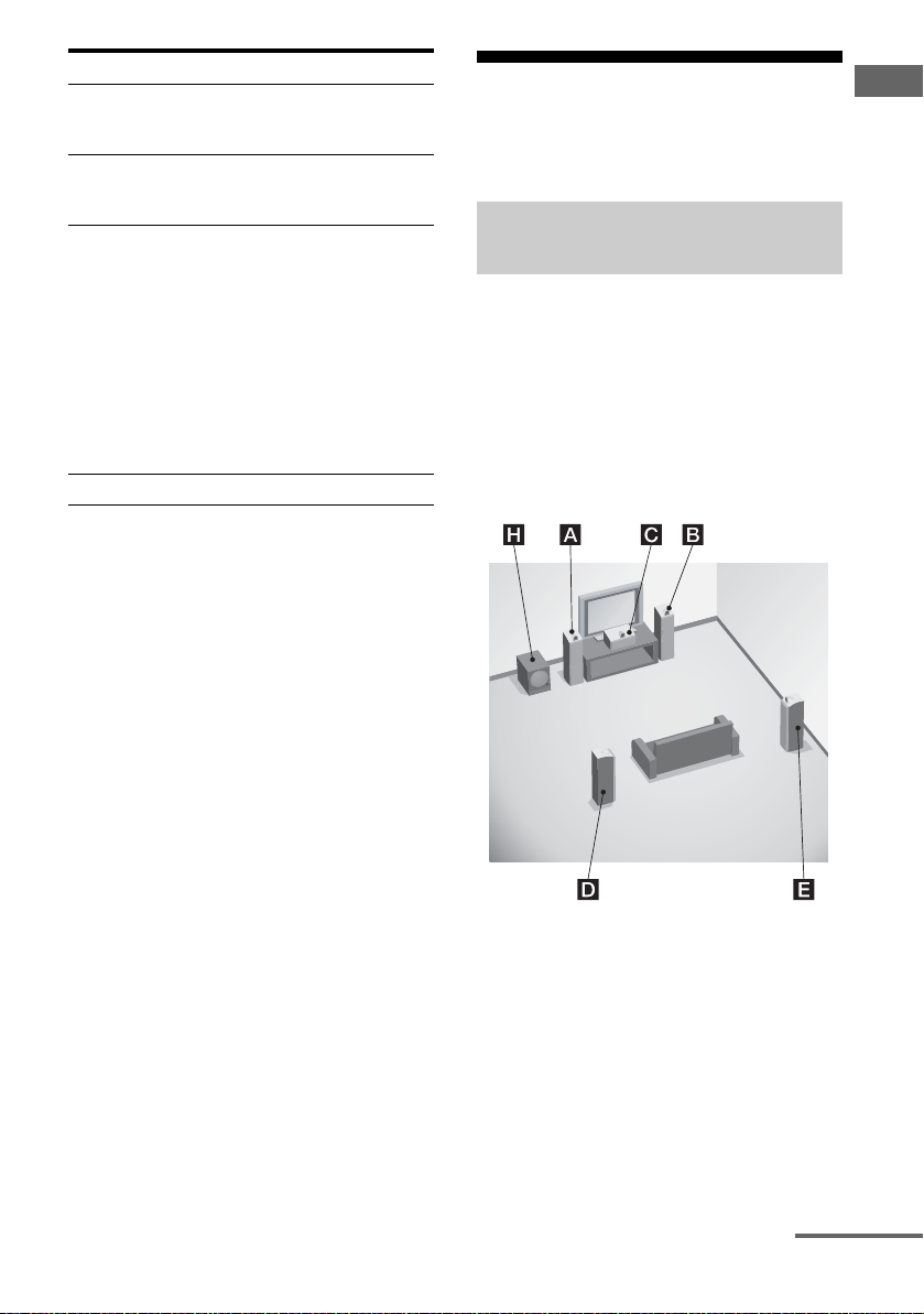
1: Installing the speakers
This receiver allows you to use a 7.1 channel
system (7 speakers and one subwoofer).
Enjoying a 5.1/7.1 channel
system
To fully enjoy theater-like multi channel
surround sound requires five speakers (two
front speakers, a center speaker, and two
surround speakers) and a subwoofer (5.1
channel system).
Example of a 5.1 channel
speaker system configuration
Getting Started
AFront speaker (left)
BFront speaker (right)
CCenter speaker
DSurround speaker (left)
ESurround speaker (right)
HSubwoofer
continued
13
US
Page 14
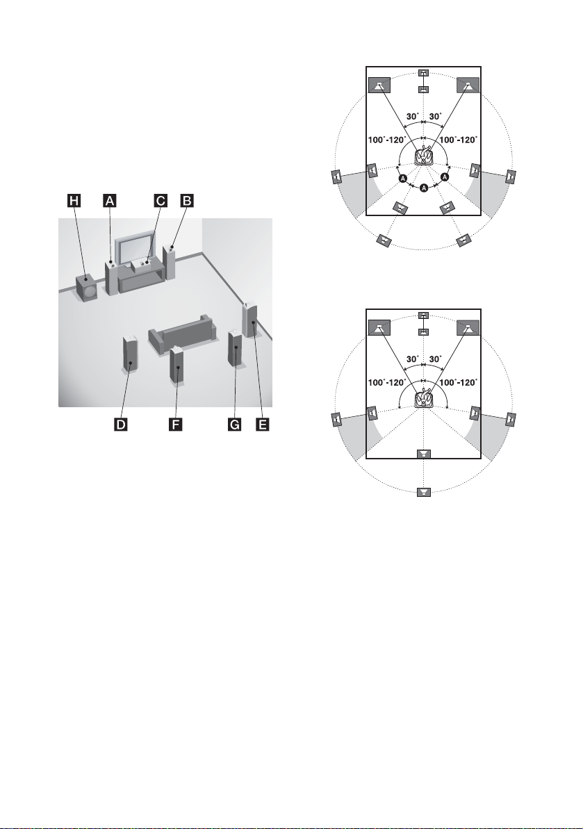
You can enjoy high fidelity reproduction of
DVD software recorded sound in the Surround
EX format if you connect one additional
surround back speaker (6.1 channel system) or
two surround back speakers (7.1 channel
system).
Example of a 7.1 channel
speaker system configuration
Tips
• The angle A should be the same.
• When you connect a 6.1 channel speaker system,
place the surround back speaker behind the seating
position.
AFront speaker (left)
BFront speaker (right)
CCenter speaker
DSurround speaker (left)
ESurround speaker (right)
FSurround back speaker (left)
GSurround back speaker (right)
HSubwoofer
US
14
• Since the subwoofer does not emit highly
directional signals, you can place it wherever you
want.
Page 15
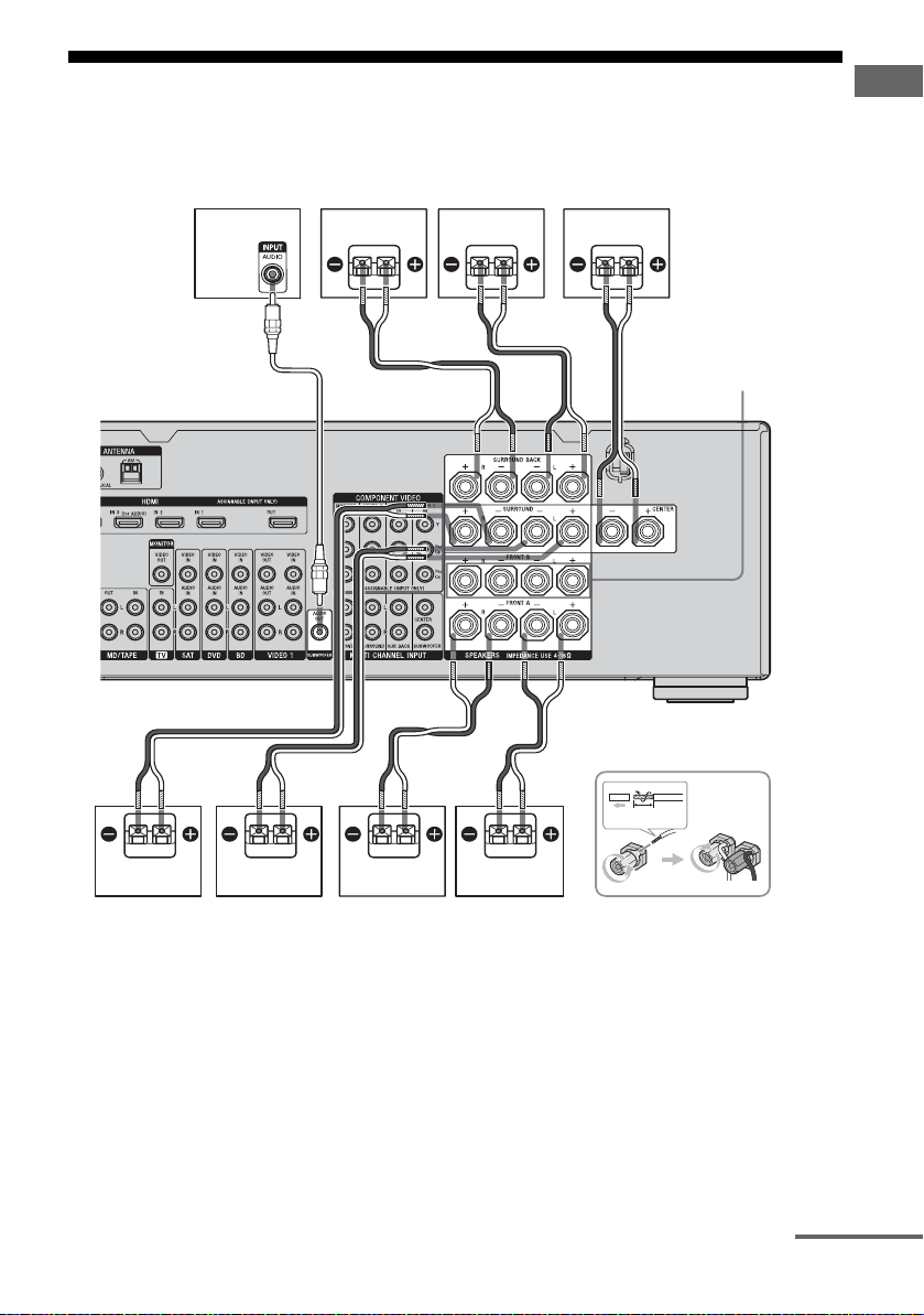
2: Connecting the speakers
Before connecting the cords, be sure to
disconnect the AC power cord.
Getting Started
HGF
AB
C
SPEAKERS FRONT
B terminals
B
13
32"
/
(10 mm)
a)
A Monaural audio cord (not supplied)
B Speaker cords (not supplied)
AFront speaker A (left)
BFront speaker A (right)
CCenter speaker
DSurround speaker (left)
ADEB
ESurround speaker (right)
FSurround back speaker (left)
GSurround back speaker (right)
HSubwoofer
c)
continued
b)
b)
US
15
Page 16

a)
If you have an additional front speaker
system, connect them to the SPEAKERS
FRONT B terminals. You can select the front
speaker system you want to use with
SPEAKERS (OFF/A/B/A+B) on the front
panel (page 40).
b)
If you connect only one surround back
speaker, connect it to the SPEAKERS
SURROUND BACK L terminals.
c)
When you connect a subwoofer with an auto
standby function, turn off the function when
watching movies. If the auto standby
function is set to on, it turns to standby mode
automatically based on the level of the input
signal to a subwoofer, then sound may not be
output.
Notes
• When you connect all the speakers with a nominal
impedance of 8 ohms or higher, set “Impedance” in
the Speaker settings menu to “8 Ω”. In other
connections, set it to “4 Ω”. For details, see “8:
Setting the speakers” (page 39).
• Before connecting the AC power cord, make sure
that metallic wires of the speaker cords are not
touching each other between the SPEAKERS
terminals.
16
US
Page 17
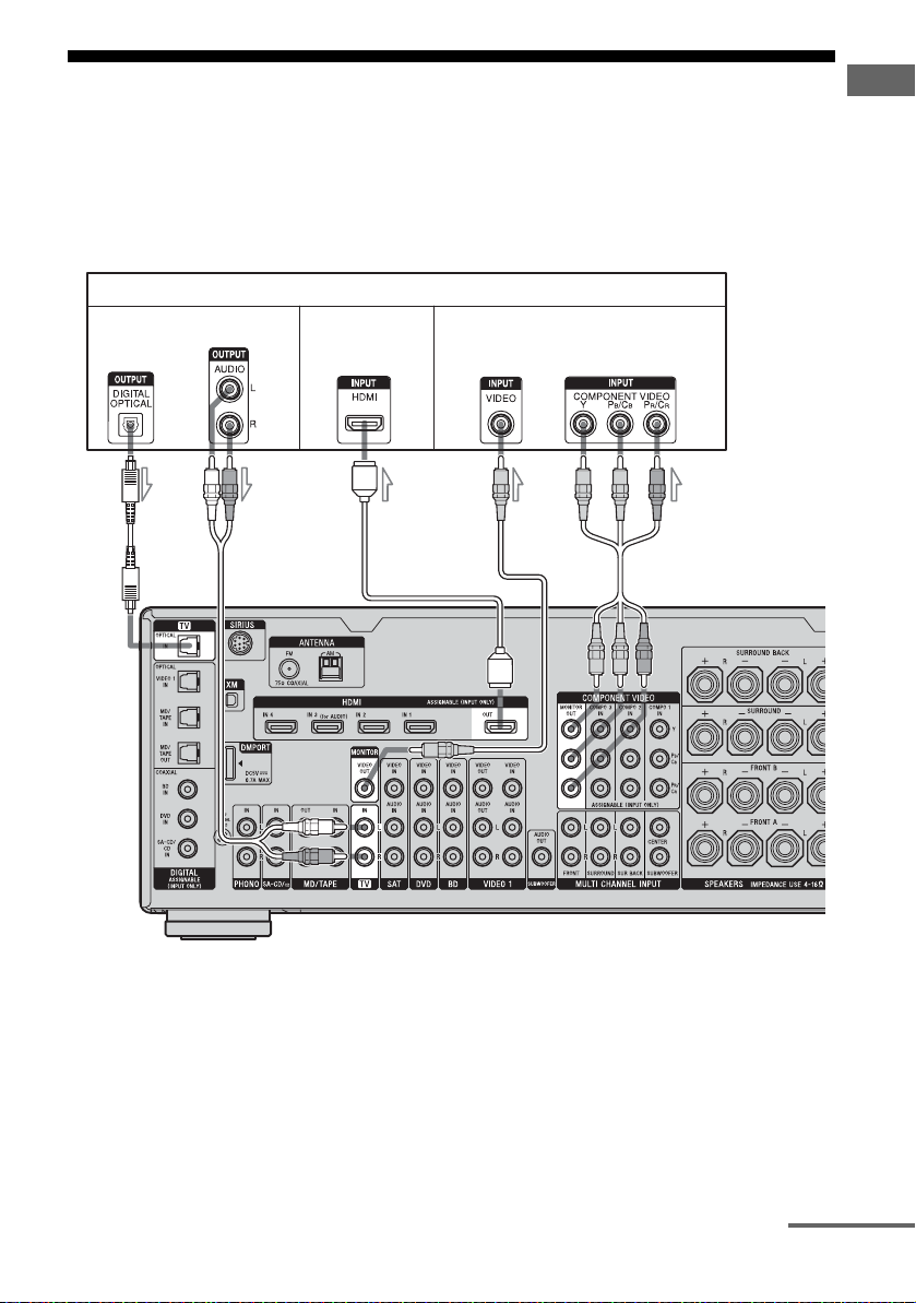
3: Connecting the TV
You can watch the selected input image when
you connect the MONITOR OUT or HDMI
OUT jack to a TV. You can operate this
receiver using a GUI (Graphical User
Interface).
TV
Audio signals
Audio/video
signals
Getting Started
It is not necessary to connect all the cords.
Connect the audio and video cords according
to the jacks of your components. Before
connecting the cords, be sure to disconnect the
AC power cord.
Video signals
AB
C
A Optical digital cord (not supplied)
B Audio cord (not supplied)
C HDMI cable (not supplied)
We recommend that you use a Sony HDMI cable.
D Video cord (not supplied)
E Component video cord (not supplied)
D
E
continued
17
US
Page 18

Notes
• Be sure to turn on the receiver when the video and
audio signals of a playback component are being
output to a TV via the receiver. Unless the power is
turned on, neither video nor audio signals will be
transmitted.
• Depending on the status of the connection between
the TV and the antenna, the image on the TV
screen may be distorted. In this case, place the
antenna farther away from the receiver.
• When connecting optical digital cords, insert the
plugs straight in until they click into place.
• Do not bend or tie optical digital cords.
Tips
• The receiver has a video conversion function. For
details, see “Notes on converting video signals”
(page 31).
• The sound of the TV is output from the speakers
connected to the receiver if you connect the audio
output jack of the TV and the TV IN jacks of the
receiver. In this configuration, set the audio output
jack of the TV to “Fixed” if it can be switched
between either “Fixed” or “Variable”.
• The screen saver is activated when the GUI menu
is displayed on the TV screen and there has been no
operation attempted for 15 minutes.
• All the digital audio jacks are compatible with
32 kHz, 44.1 kHz, 48 kHz, and 96 kHz sampling
frequencies.
4a: Connecting the audio components
How to hook up your
components
This section describes how to hook up your
components to this receiver. Before you begin,
see “Component to be connected” below for
the pages which describe how to connect each
component. Before connecting the cords, be
sure to disconnect the AC power cord.
After hooking up all your components,
proceed to “5: Connecting the antennas”
(page 33).
Component to be connected Page
Super Audio CD
player, CD player
MD deck With digital audio
Tape deck, Analog disc turntable 22
DIGITAL MEDIA PORT adapter 19
With digital audio
output
With multi channel
audio output
With analog audio
output only
output
With analog audio
output only
19
21
22
19
22
18
Notes
• When connecting optical digital cords, insert the
plugs straight in until they click into place.
• Do not bend or tie optical digital cords.
Tip
All the digital audio jacks are compatible with
32 kHz, 44.1 kHz, 48 kHz, and 96 kHz sampling
frequencies.
US
Page 19
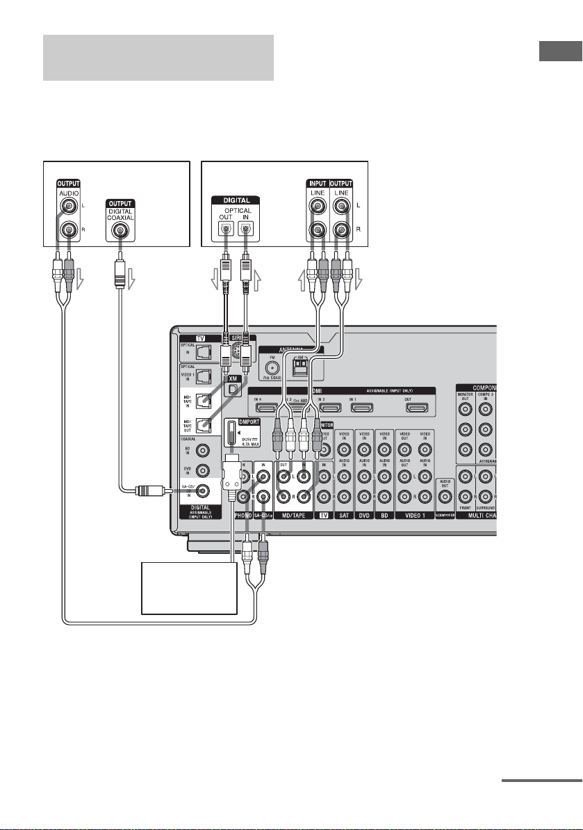
Connecting components with
digital audio input/output jacks
The following illustration shows how to
connect a Super Audio CD player, CD player,
an MD deck and DIGITAL MEDIA PORT
adapter.
Getting Started
Super Audio CD
player, CD player
DIGITAL MEDIA
PORT adapter
MD deck
C
ABA
A Audio cord (not supplied)
B Coaxial digital cord (not supplied)
C Optical digital cord (not supplied)
continued
19
US
Page 20

Notes on connecting a DIGITAL
MEDIA PORT adapter
• When connecting the DIGITAL MEDIA
PORT adapter, be sure the connector is
inserted with the arrow mark facing towards
the arrow mark on the DMPORT jack.
• Be sure to make DMPORT connections
firmly, insert the connector straight in.
• As the connector of the DIGITAL MEDIA
PORT adapter is fragile, be sure to handle
with care when placing or moving the
receiver.
• To disconnect the DIGITAL MEDIA PORT
adapter, squeeze the sides of the connector,
since the connector is locked in place.
Notes on playing a Super Audio
CD on a Super Audio CD player
• No sound is output when playing a Super
Audio CD on a Super Audio CD player
connected to only the COAXIAL SA-CD/
CD IN jack on this receiver. When you play
a Super Audio CD, connect the player to the
MULTI CHANNEL INPUT or SA-CD/CD
IN jacks on this receiver. Refer to the
operating instructions supplied with the
Super Audio CD player.
• You cannot make digital recordings of a
Super Audio CD.
If you want to connect several
digital components, but cannot
find an unused input
See “Enjoying the sound/images from other
inputs” (page 94).
US
20
Page 21
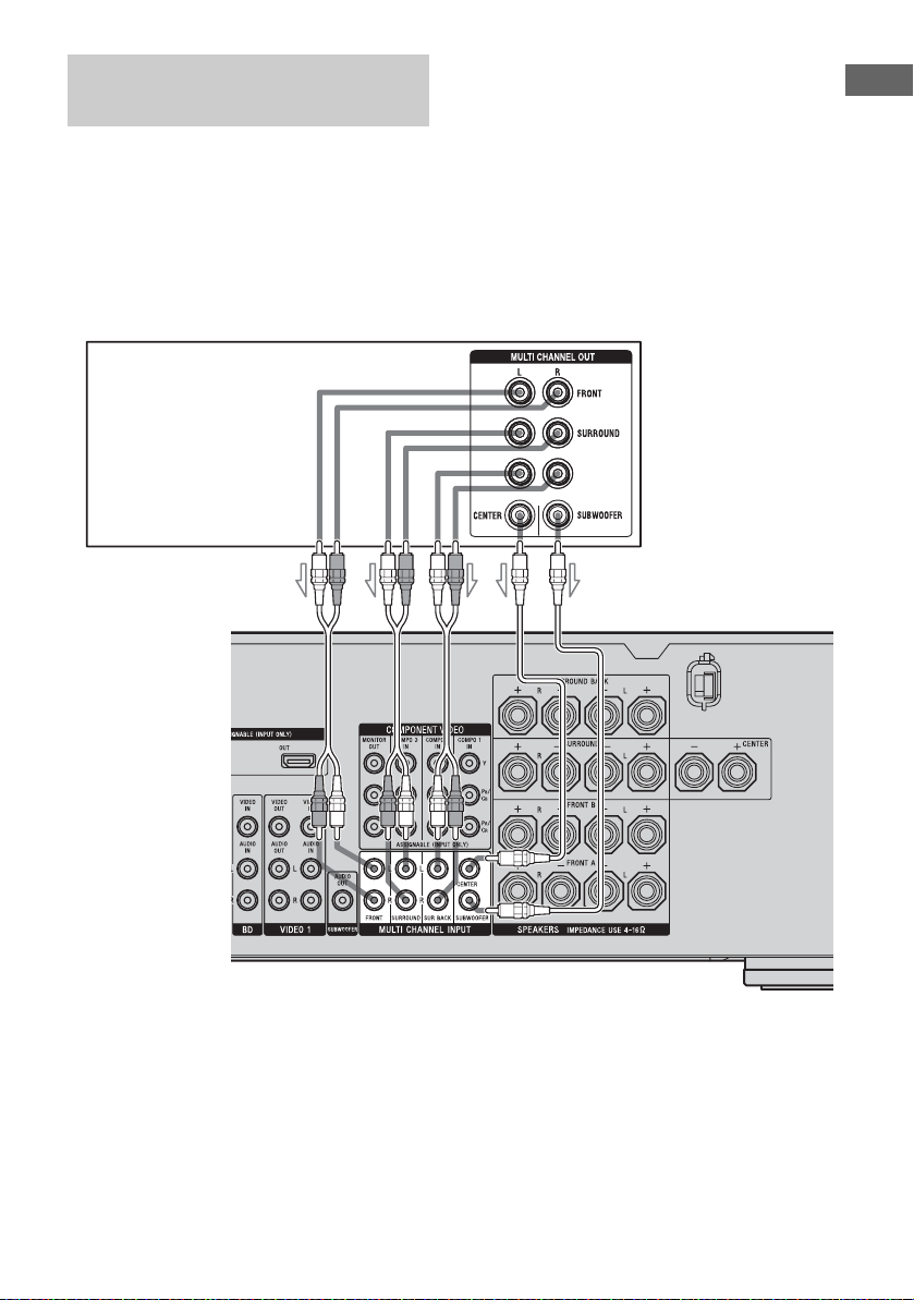
Connecting components with
multi channel output jacks
If your DVD player, Blu-ray disc player or
Super Audio CD player is equipped with multi
channel output jacks, you can connect them to
the MULTI CHANNEL INPUT jacks of this
receiver to enjoy multi channel sound.
Alternatively, the multi channel input jacks
can be used to connect an external multi
channel decoder.
DVD player, Blu-ray disc player,
Super Audio CD player, etc.
AB
SURROUND
BACK
Getting Started
A Audio cord (not supplied)
B Monaural audio cord (not supplied)
Notes
• DVD players, Blu-ray disc players and Super
Audio CD players may not have the SURROUND
BACK jacks.
• When “Sur Back Assign” is set to “BI-AMP” in the
Speaker settings menu, the input to the SUR BACK
jacks is invalid.
• Audio signals input from the MULTI CHANNEL
INPUT jacks are not output to other audio output
jacks. The signals cannot be recorded.
21
US
Page 22
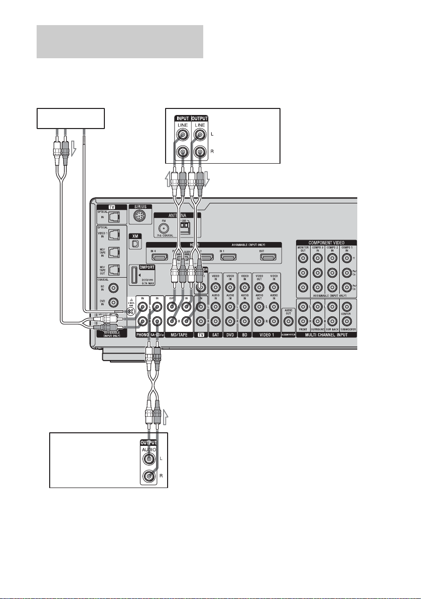
Connecting components with
analog audio jacks
The following illustration shows how to
connect a component with analog jacks, such
as a tape deck, turntable, etc.
Tu r nt a b le
A
MD deck,
Tape deck
AA
Super Audio CD player,
CD player
A Audio cord (not supplied)
Note
If your turntable has a ground (earth) wire, connect
it to the (U) SIGNAL GND terminal.
US
22
Page 23
4b: Connecting the video components
Getting Started
How to hook up your
components
This section describes how to hook up your
components to this receiver. Before you begin,
see “Component to be connected” below for
the pages which describe how to connect each
component.
Before connecting the cords, be sure to
disconnect the AC power cord.
After hooking up all your components,
proceed to “5: Connecting the antennas”
(page 33).
Component to be connected Page
TV 17
With HDMI jack 24
DVD player 26
Blu-ray disc player 27
Satellite tuner, set-top box 28
DVD recorder, VCR 29
Camcorder, video game, etc. 29
If you want to connect several
digital components, but cannot
find an unused input
See “Enjoying the sound/images from other
inputs” (page 94).
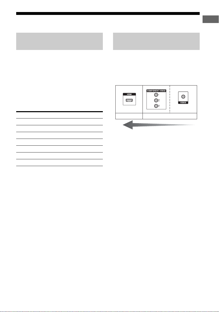
Video input/output jacks to be
connected
The image quality depends on the connecting
jack. See the illustration that follows. Select
the connection according to the jacks on your
components.
Digital Analog
High quality image
Note
Be sure to turn on the receiver when the video and
audio signals of a playback component are being
output to a TV via the receiver. Unless the power is
turned on, neither video nor audio signals will be
transmitted.
Notes
• When connecting optical digital cords, insert the
plugs straight in until they click into place.
• Do not bend or tie optical digital cords.
Tip
All the digital audio jacks are compatible with
32 kHz, 44.1 kHz, 48 kHz, and 96 kHz sampling
frequencies.
23
US
Page 24
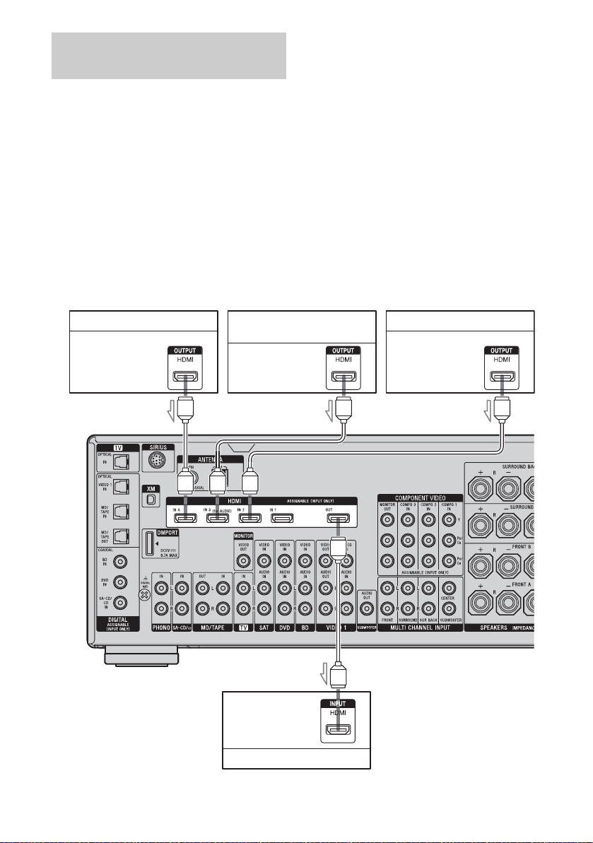
Connecting components with
HDMI jacks
HDMI is the abbreviated name for HighDefinition Multimedia Interface. It is an
interface which transmits video and audio
signals in digital format.
HDMI features
• A digital audio signal transmitted by HDMI
can be output from the speakers connected to
this receiver. This signal supports Dolby
Digital, DTS, and Linear PCM.
• This receiver can receive multi channel
Linear PCM (up to 8 channels) with a
sampling frequency of 192 kHz or less with
an HDMI connection.
• Analog video signals input to the VIDEO
jack or COMPONENT VIDEO jacks can be
up-converted as HDMI signals. Audio
signals are not output from an HDMI OUT
jack when the image is converted.
• This receiver supports High Bitrate Audio
(DTS-HD Master Audio, Dolby TrueHD)
and HDMI (Deep Color, x.v.Color).
• This receiver supports the Control for HDMI
function. For details, see “Control for
HDMI” (page 83).
• HDMI 3 input has a better sound quality.
When you need a higher sound quality,
connect your component to the HDMI IN 3
(for AUDIO) jack and select HDMI 3 as
input.
Audio/video
signals
hard disk recorder
Audio/video
signals
DVD playe rSatellite tuner, set-top box Blu-ray disc player, PS3™,
Audio/video
signals
AAA
A
Audio/video
signals
A HDMI cable (not supplied)
US
24
TV, projector, etc.
Page 25

Notes on connecting cables
• We recommend that you use a Sony HDMI
cable.
• We recommend that you use an HDMI cable
with the HDMI logo (made by Sony) for the
HDMI jack corresponding to high speed
(HDMI version 1.3a, category 2 cable) when
you view images or listen to sound during
Deep Color transmission or when you watch
a video image of 1080p or higher.
• We do not recommend using an HDMI-DVI
conversion cable. When you connect an
HDMI-DVI conversion cable to a DVI-D
component, the sound and/or the image may
not be output. Connect other audio cords or
digital connecting cords, then set “Input
Assign” in the Input Option menu when the
sound is not output correctly.
Notes on HDMI connections
• An audio signal input to the HDMI IN jack
is output from the speaker output jacks and
HDMI OUT jack. It is not output from any
other audio jacks.
• A video signal input to the HDMI IN jack
can only be output from the HDMI OUT
jack. The video input cannot be output from
the VIDEO OUT jacks or MONITOR OUT
jacks.
• The audio and video signals of HDMI input
are not output from the HDMI OUT jack
while the receiver menu is displayed.
• When you want to listen to the sound from
the TV speaker, set “Audio Out” to
“TV+AMP” in the HDMI settings menu. If
set to “AMP”, the sound is not output from
the TV speaker.
• DSD signals of Super Audio CD are not
input and output.
• Audio signals (sampling frequency, bit
length, etc.) transmitted from an HDMI jack
may be suppressed by the connected
component. Check the setup of the
connected component if an image is poor or
the sound does not come out of a component
connected via the HDMI cable.
• Sound may be interrupted when the
sampling frequency, the number of channels
or the audio format of the audio output
signals from the playback component is
switched.
• When the connected component is not
compatible with copyright protection
technology (HDCP), the image and/or the
sound from the HDMI OUT jack may be
distorted or may not be output.
In this case, check the specification of the
connected component.
• You can enjoy High Bitrate Audio (DTS-HD
Master Audio, Dolby TrueHD), multi
channel Linear PCM only with an HDMI
connection.
• Set the image resolution of the playback
component to more than 720p/1080i to
enjoy High Bitrate Audio (DTS-HD Master
Audio, Dolby TrueHD).
• The image resolution of the playback
component may need certain settings be
made before you can enjoy multi channel
Linear PCM. Refer to the operating
instructions of the playback component.
• Not every HDMI component supports all
functions that are defined by the specified
HDMI version. For example, components
that support HDMI version 1.3a, may not
support Deep Color.
• Refer to the operating instructions of each
connected component for details.
Getting Started
25
US
Page 26
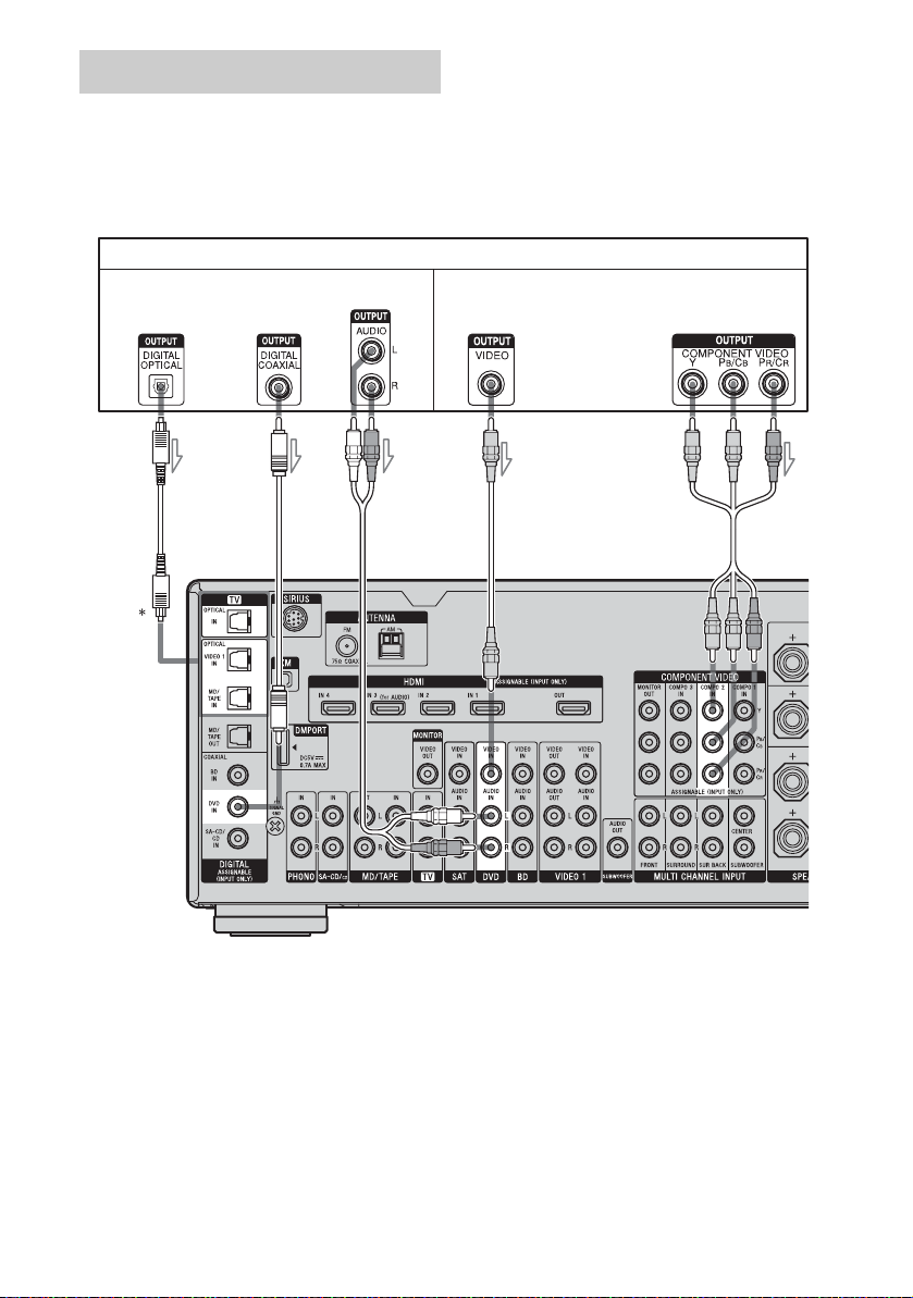
Connecting a DVD player
The following illustration shows how to
connect a DVD player.
It is not necessary to connect all the cords.
Connect the audio and video cords according
to the jacks of your components.
Audio signals
Note
To input multi channel digital audio from the DVD
player, set the digital audio output setting on the
DVD player. Refer to the operating instructions
supplied with the DVD player.
DVD player
Video signals
A
BC
A Optical digital cord (not supplied)
B Coaxial digital cord (not supplied)
C Audio cord (not supplied)
* When you connect a component equipped with an
OPTICAL jack, set “Input Assign” in the Input
menu.
D
E
D Video cord (not supplied)
E Component video cord (not supplied)
Tip
The COMPONENT VIDEO COMPO 2 IN jacks
have been assigned to the DVD player. If you
connect your DVD player to the COMPONENT
VIDEO COMPO 1 or COMPO 3 IN jacks, set
“Input Assign” in the Input menu.
26
US
Page 27
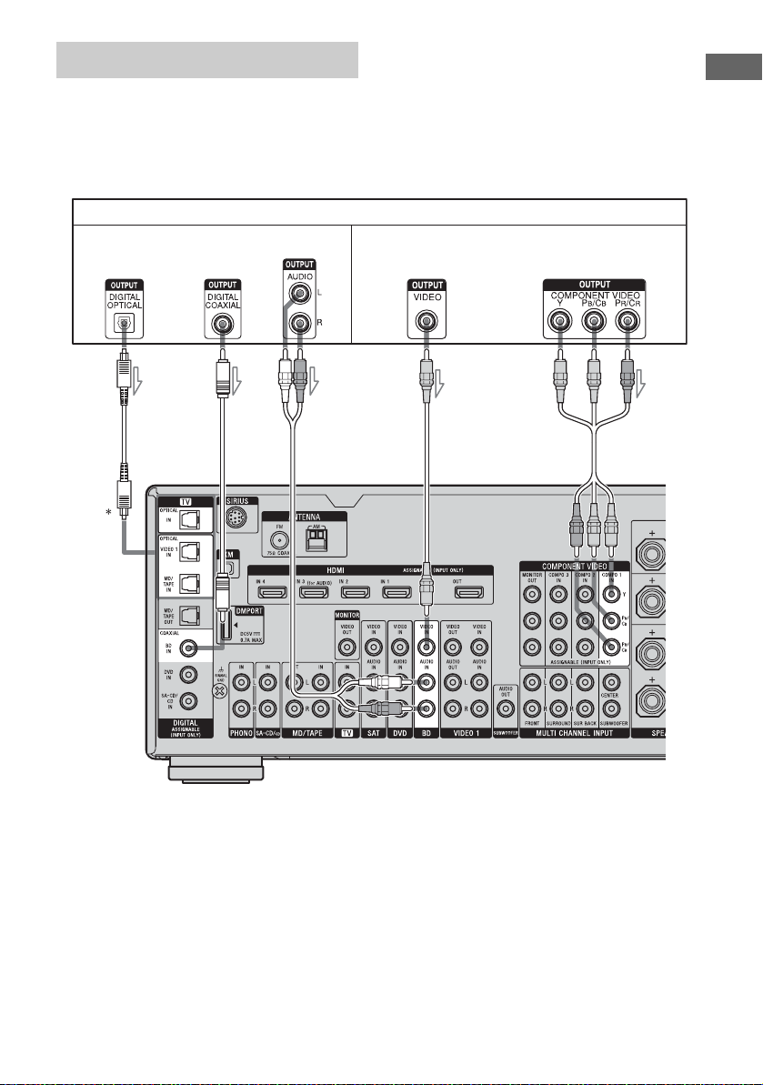
Connecting a Blu-ray disc player
The following illustration shows how to
connect a Blu-ray disc player.
It is not necessary to connect all the cords.
Connect the audio and video cords according
to the jacks of your components.
Blu-ray disc player
Audio signals Video signals
Note
To input multi channel digital audio from the Bluray disc player, set the digital audio output setting on
the Blu-ray disc player. Refer to the operating
instructions supplied with the Blu-ray disc player.
Getting Started
ABC
A Optical digital cord (not supplied)
B Coaxial digital cord (not supplied)
C Audio cord (not supplied)
* When you connect a component equipped with an
OPTICAL jack, set “Input Assign” in the Input
menu.
D
E
D Video cord (not supplied)
E Component video cord (not supplied)
Tip
The COMPONENT VIDEO COMPO 1 IN jacks
have been assigned to the Blu-ray disc player. If you
connect your Blu-ray disc player to the
COMPONENT VIDEO COMPO 2 or COMPO 3 IN
jacks, set “Input Assign” in the Input menu.
27
US
Page 28
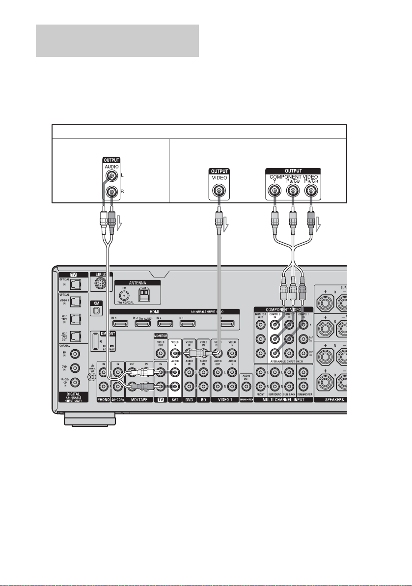
Connecting a satellite tuner,
set-top box
The following illustration shows how to
connect a satellite tuner or set-top box.
It is not necessary to connect all the cords.
Connect the audio and video cords according
to the jacks of your components.
Satellite tuner, set-top box
Audio signals Video signals
ABC
A Audio cord (not supplied)
B Video cord (not supplied)
C Component video cord (not supplied)
Tip
The COMPONENT VIDEO COMPO 3 IN jacks
have been assigned to the satellite tuner or set-top
box. If you connect your satellite tuner or set-top
box to the COMPONENT VIDEO COMPO 1 or
COMPO 2 IN jacks, set “Input Assign” in the Input
menu.
US
28
Page 29
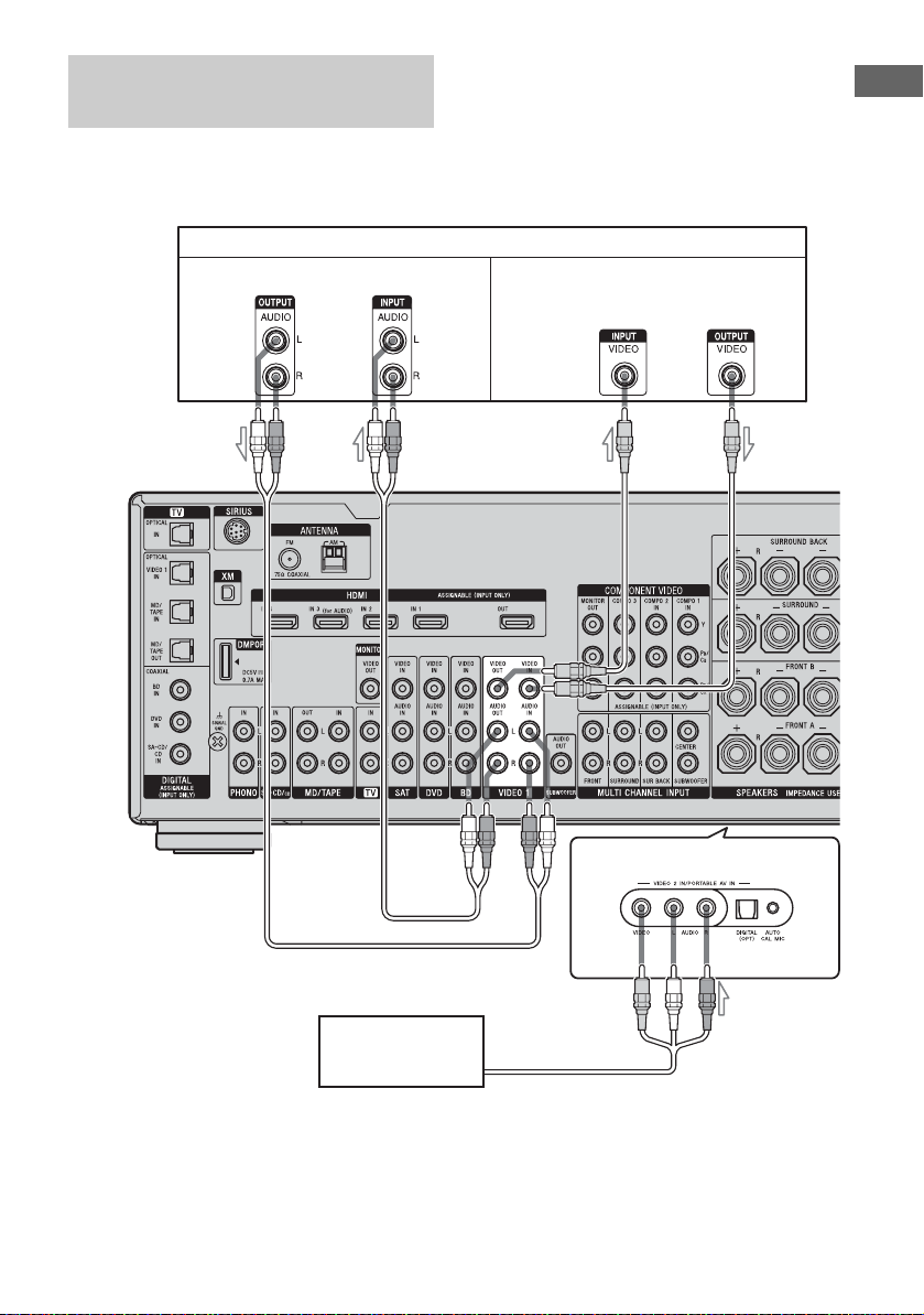
Connecting components with
analog video and audio jack
The following illustration shows how to
connect a component which has analog jacks
such as a DVD recorder, VCR, etc.
Audio signals Video signals
It is not necessary to connect all the cords.
Connect the audio and video cords according
to the jacks of your components.
DVD recorder, VCR
Getting Started
A
Camcorder,
video game
B
(On the front panel)
C
A Audio cord (not supplied)
B Video cord (not supplied)
C Audio/video cord (not supplied)
29
US
Page 30
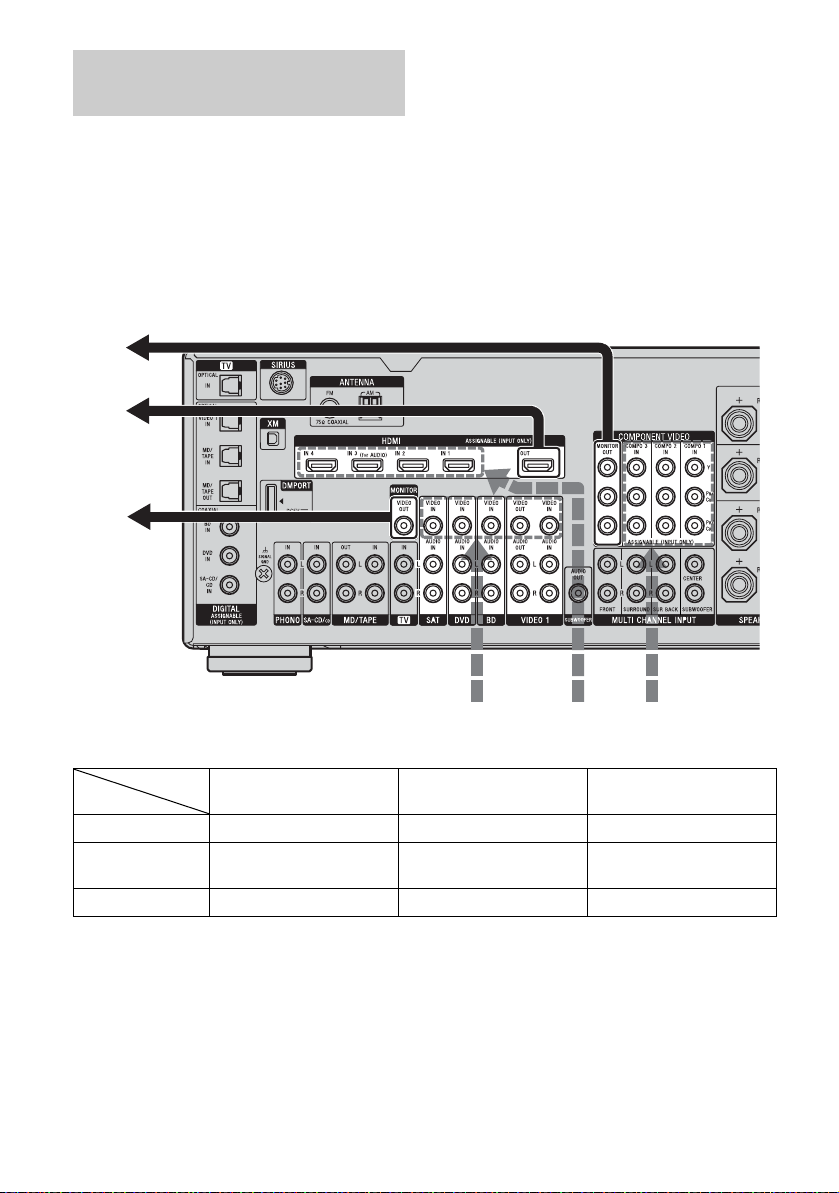
Function for conversion of video
signals
This receiver is equipped with a function for
converting video signals. You can output the
video signal after connecting this receiver via
the MONITOR OUT or HDMI OUT jack as
shown in the illustration.
• Video signals can be up-converted as HDMI
video and component video signals.
• Component video signals can be output as
HDMI video and video signals.
For details on the video converting function,
see “In the video input/output conversion table
classified by the menu settings” (page 32).
In the video input/output conversion table of the receiver
Output Signals
BC
ABC
BC
C
OUTPUT jack
INPUT jack
HDMI IN 1/2/3/4 A f XX
COMPONENT
VIDEO IN B
VIDEO IN C aaa/f*
a : Video signals are converted and output through the video converter.
f : The same type of signal as that of the input signal is output. Video signals are not converted.
X : Video signals are not output.
* Video signals are output when “Resolution” is set to “DIRECT” in the Video settings menu.
US
30
HDMI OUT
aa/fa
COMPONENT VIDEO
MONITOR OUT
AB
Input Signals
MONITOR VIDEO OUT
Page 31

Notes on converting video signals
• When video signals from a VCR, etc., are
converted on this receiver and then output to
your TV, depending on the status of the
video signal output, the image on the TV
screen may appear distorted horizontally or
no image may be output.
• HDMI video signals cannot be converted to
component video signals and video signals.
• The converted video signals are output only
from the MONITOR OUT jacks. They are
not output from the VIDEO OUT jacks.
• When you play a VCR with an image
improvement circuit, such as Time Base
Corrector (TBC), the images may be
distorted or may not be output. In this case,
set the image improvement circuit function
to off.
• The resolution of the signals output to the
COMPONENT VIDEO MONITOR OUT
jacks is converted up to 1080i. The
resolution of the signals output to the HDMI
OUT jack is converted up to 1080p.
• COMPONENT VIDEO MONITOR OUT
jacks have restrictions on resolution when
the resolution of video signals protected by
copyright technology is converted.
Resolution of up to 480p can be output to the
COMPONENT VIDEO MONITOR OUT
jacks. The HDMI OUT jack has no
restriction on resolution.
• Video signals for which the resolution has
been converted can be output from either the
COMPONENT VIDEO MONITOR OUT
jacks or the HDMI OUT jack. The video
signals are output from the HDMI OUT jack
when both are connected.
• Set “Resolution” to “AUTO” or “480i/576i”
in the Video settings menu to output the
video signals from the MONITOR VIDEO
OUT or COMPONENT VIDEO MONITOR
OUT jack when both are connected.
To display Closed Caption
Set “Resolution” to “DIRECT” in the Video
settings menu when receiving a signal that
supports Closed Captions.
Use the same kind of cords for the input/output
signals.
Getting Started
continued
31
US
Page 32

In the video input/output conversion table classified by the menu
settings
For details on “Resolution” menu setting, see “Settings for the video (Video settings menu)”
(page 54) and on operating, see “Converting analog video input signals” (page 88).
“Resolution”
menu setting
Output from
Input signals
HDMI OUT jack COMPONENT
VIDEO MONITOR
OUT jacks
MONITOR VIDEO
OUT jack
DIRECT Component video X f X
Vid eo XXf
AUTO (initial
setting)
Component video a
Vid eo a
480i/576i Component video a
Vid eo a
a)
a)
c)
c)
b)
a
b)
a
b)
a
b)
a
aa
aa
480p/576p Component video aaX
Vid eo aaf
720p, 1080i Component video aa
Vid eo aa
d)
d)
X
f
1080p Component video afX
Vid eo a X f
a : Video signals are converted and output through the video converter.
f : The same type of signal as that of the input signal is output. Video signals are not converted.
X : Video signals are not output.
a)
This resolution is set automatically, depending on the connected TV.
b)
When the TV is connected to jacks other than the HDMI jacks, 480i/576i signals are output when
“Resolution” is set to “AUTO”.
c)
480p/576p signals are output even if 480i/576i is set.
d)
Video signals without copyright protection are output based on the settings menu. Video signals with
copyright protection are output as 480p.
Notes
• Video signals are not output from the COMPONENT VIDEO MONITOR OUT or MONITOR VIDEO OUT
jack when the TV, etc., is connected to the HDMI OUT jack.
• If you select a resolution that the connected TV does not support in the “Resolution” menu, the images from
the TV cannot be output correctly.
• Converted HDMI image output signals do not support “x.v.Color” and Deep Color.
32
US
Page 33

5: Connecting the antennas
Connect the supplied AM loop antenna and
FM wire antenna.
Before connecting the antennas, be sure to
disconnect the AC power cord.
FM wire antenna (supplied)
AM loop antenna
(supplied)
Getting Started
Notes
• To prevent noise pickup, keep the AM loop antenna
away from the receiver and other components.
• Be sure to fully extend the FM wire antenna.
• After connecting the FM wire antenna, keep it as
horizontal as possible.
33
US
Page 34

6: Preparing the receiver and the remote
Connecting the AC power cord
Connect the AC power cord to a wall outlet.
Note
Before connecting the AC power cord, make sure
that metallic wires of the speaker cords are not
touching each other between the SPEAKERS
terminals.
AC power cord
To the wall outlet
Performing initial setup
operations
Before using the receiver for the first time,
initialize the receiver by performing the
following procedure. This procedure can also
be used to return settings you have made to
their factory defaults.
Be sure to use the buttons on the receiver for
this operation.
1,2 2,3
2,3
1 Press POWER to turn off the
receiver.
2 While holding down TONE
MODE and 2CH/A.DIRECT,
press POWER to turn on the
receiver.
3 Release TONE MODE and 2CH/
A.DIRECT after a few seconds.
After “CLEARING” appears on the
display window for a while,
“CLEARED !” appears.
All the settings you have changed or
adjusted are reset to the initial settings.
34
US
Page 35

Inserting batteries into the
remote
Insert two R6 (size-AA) batteries in the RMAAL019 Remote Commander.
Observe the correct polarity when installing
batteries.
Notes
• Do not leave the remote in an extremely hot or
humid place.
• Do not use a new battery with old ones.
• Do not mix manganese batteries and other kinds of
batteries.
• Do not expose the remote sensor to direct sunlight
or lighting apparatuses. Doing so may cause a
malfunction.
• If you do not intend to use the remote for an
extended period of time, remove the batteries to
avoid possible damage from battery leakage and
corrosion.
• When you replace the batteries, the programmed
remote codes may be cleared. If this happens,
program the remote codes again (page 115).
Tip
When the remote no longer operates the receiver,
replace all the batteries with new ones.
About the command mode
The receiver and the remote use the same
command mode.
If the command modes of the receiver and the
remote are different, you cannot use the
remote to operate the receiver.
If the command modes of both the receiver and
the remote are those of the initial setting (AV
SYSTEM 2), it is not necessary to reset them.
You can switch the command mode (AV
SYSTEM 1 or AV SYSTEM 2) of the receiver
and the remote. If both the receiver and the
other Sony component respond to the same
remote command, switch the command mode
of either the component or the receiver to
another command mode so that the component
does not respond to the same remote command
as the receiver.
To switch the command mode
of the receiver
POWER
2CH/A.DIRECT
While holding down 2CH/
A.DIRECT, press POWER to turn on
the receiver.
When the command mode is set to “AV2”,
“C. MODE AV2” appears on the display
window.
When the command mode is set to “AV1”,
“C. MODE AV1” appears on the display
window.
Getting Started
continued
35
US
Page 36

To switch the command mode
of the RM-AAL019 remote
7: Operating the receiver
THEATER
THEATER
1
2
While holding down RM SET UP, press
1
SHIFT
SHIFT
1
1
VIDEO2VIDEO1
VIDEO2VIDEO1
456
456
SAT
SAT
789
789
PHONO
TUNER
PHONO
TUNER
-/--
0/10
-/--
0/10
HDMI2HDMI1 HDMI3 HDMI4
HDMI2HDMI1 HDMI3 HDMI4
SIRIUS
SIRIUS
XM
XM
2CH/
2CH/
A.F.D.
A.DIRECT
A.F.D.
A.DIRECT
INPUT
INPUT
MODERESOLUTION
MODERESOLUTION
23
23
BD DVD
BD DVD
MD/
MD/
TV
TV
TAPE
TAPE
MULTI
MULTI
IN
IN
ENT/MEM
ENT/MEM
AMPTV
AMPTV
TV INPUT
TV INPUT
WIDE
WIDE
SA-CD/
SA-CD/
CD
CD
D.TUNING
D.TUNING
DMPORT
DMPORT
CLEAR
CLEAR
MUSICMOVIE
MUSICMOVIE
NIGHT
NIGHT
MODESLEEP
MODESLEEP
GUI
GUI
MODE
MODE
1
AMPSHIFT
3
?/1.
The AMP button flashes and the SHIFT
button lights up.
2 Press 1 or 2 while the AMP button is
flashing.
The AMP button lights up.
When you press 1, the command mode is
set to AV SYSTEM 1. When you press 2,
the command mode is set to AV SYSTEM
2.
3 Press ENT/MEM before the AMP
button lights off.
The AMP button flashes twice, then the
command mode setting process is
completed.
using the GUI
(Graphical User
Interface)
You can change the display mode of the menu
to screen mode using the following
procedures. “GUI MODE” appears in the
display window in screen mode.
By using the GUI menu, you can make various
settings and adjustments.
See “Operating without connecting to the TV”
(page 103) if you are not going to use a GUI
menu.
Displaying the GUI menu on the
TV screen
THEATER
SHIFT
1
23
VIDEO2VIDEO1
456
TV
SAT
789
PHONO
TUNER
-/--
0/10
HDMI2HDMI1 HDMI3
SIRIUS
XM
2CH/
A.F.D.
A.DIRECT
INPUT
MODERESOLUTION
BD DVD
MD/
TAPE
MULTI
IN
ENT/MEM
AMPTV
TV INPUT
WIDE
SA-CD/
CD
D.TUNING
DMPORT
CLEAR
HDMI4
MUSICMOVIE
NIGHT
MODESLEEP
GUI
MODE
2
3
36
4
HOME
MENU
1 Connect a TV to this receiver.
See “3: Connecting the TV” (page 17).
2 Turn on the receiver and the TV.
US
Page 37

3 Press GUI MODE repeatedly.
“GUI MODE” appears in the display
window of the receiver and the GUI menu
appears on the TV screen. Press MENU if
the GUI menu does not appear on the TV
screen.
4 Press V/v repeatedly to select a
menu you want, then press
or b.
Overview of the menus
The following menu items are available in
each settings menu.
Settings
You can use the Settings menu to set and adjust
this receiver.
Auto Calibration
You can use the Auto Calibration settings
menu to adjust the speakers automatically.
For details, see “9: Calibrating the
appropriate speaker settings automatically
(Auto Calibration)” (page 41).
Speaker
You can use the Speaker settings menu to
adjust the speakers manually for the current
position, and to set the speaker impedance.
For details, see “Setting the speaker
impedances” (page 39) and see “Adjusting
the speaker settings manually” (page 63).
Surround
You can use the Surround settings menu to
select the sound field you want for your
listening pleasure. For details on adjusting
the parameters, see “Enjoying a preprogrammed sound field” (page 56).
Getting Started
Input
Selects the input to the receiver.
For details on each input, see “Selecting a
component” (page 47).
Music
You can listen to the music from an audio
component connected the DIGITAL MEDIA
PORT adapter.
For details on the Music function, see
“Enjoying the sound/images from the
components connected to the DIGITAL
MEDIA PORT” (page 89).
FM/AM/XM/SIRIUS
You can listen to the radio using the receiver.
For details on the Tuner operation, see “Tuner
Operations” (page 69).
EQ
You can use the EQ settings menu to adjust
the equalizer. For details, see “Adjusting the
equalizer” (page 68).
Audio
For details on adjusting the audio using the
Audio settings menu, see “Settings for the
audio (Audio settings menu)” (page 53).
Video
For details on adjusting the video using the
Video settings menu, see “Settings for the
video (Video settings menu)” (page 54).
HDMI
You can use the HDMI settings menu to
operate components connected to the HDMI
jacks. For details on adjusting the
parameters, see “Settings for HDMI (HDMI
settings menu)” (page 54).
continued
37
US
Page 38

System
For details on adjusting the system using the
System settings menu, see “Settings for the
system (System settings menu)” (page 55).
Navigating through menus using
the GUI
2CH/
2CH/
A.F.D.
A.DIRECT
A.F.D.
A.DIRECT
INPUT
INPUT
MODERESOLUTION
MODERESOLUTION
MUSICMOVIE
MUSICMOVIE
NIGHT
NIGHT
MODESLEEP
MODESLEEP
GUI
GUI
MODE
MODE
1
2-9
RETURN/
EXIT O
HOME
HOME
MENU
1 Press GUI MODE repeatedly to
select “GUI ON”.
“GUI MODE” appears in the display
window of the receiver and the GUI menu
appears on the TV screen. Press MENU if
the GUI menu does not appear on the TV
screen.
3 Press or b to enter the
menu.
The menu item list appears on the TV
screen.
4 Press V/v repeatedly to select
the menu item you want to
adjust.
5 Press or b to enter the menu
item.
2 Press V/v repeatedly to select a
menu you want.
US
38
6 Press V/v repeatedly to select
the parameter you want.
Page 39

7 Press to enter the
parameter.
8 Press V/v repeatedly to select
the setting you want.
9 Press to enter the setting.
To return to the previous screen
Press RETURN/EXIT O.
To exit the menu
Press MENU.
To exit “GUI MODE”
Press GUI MODE repeatedly to select “GUI
OFF”.
8: Setting the speakers
Setting the speaker impedances
Set the appropriate speaker impedance for the
speakers you are using.
2CH/
2CH/
A.F.D.
A.DIRECT
A.F.D.
A.DIRECT
INPUT
INPUT
MODERESOLUTION
MODERESOLUTION
MUSICMOVIE
MUSICMOVIE
NIGHT
NIGHT
MODESLEEP
MODESLEEP
GUI
GUI
MODE
MODE
1
2-5
HOME
HOME
MENU
1 Press GUI MODE repeatedly to
select “GUI ON”.
“GUI MODE” appears in the display
window of the receiver and the GUI menu
appears on the TV screen. Press MENU if
the GUI menu does not appear on the TV
screen.
2 Press V/v repeatedly to select
“Settings”, then press or b.
The Settings menu list appears on the TV
screen.
Getting Started
3 Press V/v repeatedly to select
“Speaker”, then press or b.
continued
39
US
Page 40

4 Press V/v repeatedly to select
“Impedance”, then press .
5 Press V/v repeatedly to select
“4 Ω” or “8 Ω” depending on
the speakers you are using,
then press .
Notes
• If you are not sure of the impedances of the
speakers, refer to the operating instructions
supplied with your speakers. (This information is
often found on the back of the speaker.)
• When you connect all speakers with a normal
impedance of 8 ohms or higher, set “Impedance” to
“8 Ω”. When connecting other types of speakers,
set it to “4 Ω”.
• When you connect front speakers to both the
SPEAKERS A and B terminals, connect the
speakers with a normal impedance of 8 ohms or
higher.
– When you connect speakers with impedance of
16 ohms or higher in both “A” and “B”
configuration:
Set “Impedance” to “8 Ω” in the Speaker
settings menu.
– For other types of speakers in other
configurations:
Set “Impedance” to “4 Ω” in the Speaker
settings menu.
Selecting the front speakers
You can select the front speakers you want to
drive.
SPEAKERS (OFF/A/B/A+B)
Press SPEAKERS (OFF/A/B/A+B)
repeatedly to select the front
speaker system you want to drive.
Note
This setting is not available when headphones are
connected.
To select Light up
The speakers connected to the
FRONT SPEAKERS A terminals.
The speakers connected to the
FRONT SPEAKERS B terminals.
The speakers connected to both the
FRONT SPEAKERS A and B
terminals (parallel connection).
To turn off the speaker output
Press SPEAKERS (OFF/A/B/A+B)
repeatedly until the “SP A”, “SP B” and “SP
A+B” indicators in the display window light
off.
“ALL OFF” appears in the display window.
SP A
SP B
SP A+B
40
US
Page 41

9: Calibrating the
appropriate speaker
settings automatically
(Auto Calibration)
The DCAC (Digital Cinema Auto Calibration)
function allows you to perform automatic
calibration as follows:
• Check the connection between each speaker
and the receiver.
• Measure the polarity of speakers.
• Measure the distance of each speaker from
your seating position automatically.
• Measure the speaker size.
• Adjust the speaker level.
• Measure the frequency characteristics.
a)
The measurement result is not utilized in the
following cases:
– The multi channel input is selected.
– “2ch Analog Direct” is being used.
b)
The measurement is not utilized in the following
cases:
– Dolby TrueHD signals with a sampling
frequency of more than 96 kHz are being
received.
– PCM signals with a sampling frequency of
more than 96 kHz are being received.
The DCAC is designed to obtain proper sound
balance in your room. However, you can adjust
the speaker levels and balance manually
according to your preference. For details, see
“Making settings with the Test Tone menu”
(page 66).
a)
a)
a)
a)b)
Before you perform the Auto
Calibration
Before you perform the Auto Calibration, set
up and connect the speakers (page 13-16).
• The AUTO CAL MIC jack is used for the
supplied optimizer microphone only. Do not
connect other microphones. Doing so may
damage the receiver and the microphone.
• During the measurement, the sound that
comes out of the speakers is very loud. The
volume of the sound cannot be adjusted. Pay
attention to the presence of children or to the
effect on your neighborhood.
• Perform the measurement in a quiet
environment to avoid the effect of noise and
get a more accurate measurement.
• If there are any obstacles in the path between
the optimizer microphone and the speakers,
the calibration cannot be performed
correctly. Remove any obstacle from the
measurement area to avoid measurement
error.
• When you use a bi-amplifier connection, set
“Sur Back Assign” to “BI-AMP” in the
Speaker settings menu before you perform
Auto Calibration.
Notes
• The Auto Calibration function does not work if
– headphones are connected.
– SPEAKERS (OFF/A/B/A+B) is set to off.
• If the muting function has been activated before
you perform Auto Calibration, the muting function
will be set to off automatically.
Getting Started
continued
41
US
Page 42

Optimizer microphone
1 Connect the supplied optimizer
microphone to the AUTO CAL
MIC jack.
2 Set up the optimizer
microphone.
Place the optimizer microphone at your
seating position. Use a stool or tripod so
that the optimizer microphone remains at
the same height as your ears.
On setting up the active
subwoofer
• When a subwoofer is connected, turn on the
subwoofer and turn up the volume
beforehand. Turn the MASTER VOLUME
knob to just before the mid-point.
• If you connect a subwoofer with the
crossover frequency function, set the value
to maximum.
• If you connect a subwoofer with an auto
standby function, set it to off (deactivated).
Note
Depending on the characteristics of the subwoofer
you are using, the setup distance value may be
further away from the actual position.
42
US
Page 43

Performing Auto Calibration
2CH/
2CH/
A.F.D.
A.DIRECT
A.F.D.
A.DIRECT
INPUT
INPUT
MODERESOLUTION
MODERESOLUTION
MUSICMOVIE
MUSICMOVIE
NIGHT
NIGHT
MODESLEEP
MODESLEEP
GUI
GUI
MODE
MODE
1
2-7
HOME
HOME
MENU
1 Press GUI MODE repeatedly to
select “GUI ON”.
“GUI MODE” appears in the display
window of the receiver and the GUI menu
appears on the TV screen. Press MENU if
the GUI menu does not appear on the TV
screen.
2 Press V/v repeatedly to select
“Settings”, then press or b.
The Settings menu list appears on the TV
screen.
3 Press V/v repeatedly to select
“Auto Calibration”, then press
or b.
4 Press V/v repeatedly to select
“Quick Setup”, then press .
5 Press V/v repeatedly and to
un-check the items you do not
want to measure.
• Speaker Distance
• Speaker Level
• Frequency Characteristic
6 Press b.
7 Press to select “Start”.
8 The measurement starts in five
seconds.
Getting Started
continued
43
US
Page 44

9 Measurement starts.
The measurement process will take
approximately 30 seconds with a test
tone. Wait until the measurement process
completes.
Tips
• Operations other than turning the receiver on or off
are deactivated during the measurement.
• When connecting special speakers, such as dipole
speakers, the measurements may not be performed
correctly or Auto Calibration cannot be performed.
To cancel the measurement
The measurement is cancelled when you
change the volume, activate the muting
function, switch functions, change the setting
of SPEAKERS (OFF/A/B/A+B), press GUI
MODE, or connect headphones.
Confirming/saving the
measurement results
1 Confirm the measurement
result.
When the measurement ends, a beep
sounds and the measurement result
appears on the TV screen.
Note
When the speaker(s) is (are) out of the phase,
“Out Phase” is displayed on the TV screen.
The “+” and “–” terminals of the speaker may
be connected the other way around. However,
depending on the speakers, “Out Phase”
appears on the TV screen even though the
speakers are connected properly. This is
because of the speakers’ specifications. In this
case, you can continue to use the receiver.
Tip
The displayed unit of distance is feet. You can
change the unit of distance to meters in
“Distance Unit” in the Speaker settings menu.
44
US
Page 45

2 Press to select “Next”.
When “Save auto calibration (auto
speaker setup) results?” appears on the
TV screen, you can select whether to
confirm the warning (“Yes”) or not
(“No”).
Follow the instructions of the TV screen
when you select “Yes”.
For details on warning and error codes,
see “Message list after Auto Calibration
measurement” (page 46).
Tip
Press on the remote when “Please Press
ENTER.” appears on the TV screen.
3 Press B/b repeatedly to select
“Yes”, then press .
Parameter Explanation
Full Flat Makes the measurement of
frequency from each
speaker flat.
Engineer Sets the frequency to one
that matches that of the
Sony listening room
standard.
Front Reference Adjusts the characteristics
of all the speakers to match
the characteristics of the
front speaker.
OFF Sets the Auto Calibration
EQ to off.
5 Press b.
The exit screen appears.
Getting Started
4 Press V/v repeatedly to select
the Auto Calibration type, then
press .
The measurement results are saved.
6 Press to exit.
Note
The frequency response measurement result is not
utilized in the following cases.
– The multi channel input is selected.
– “2ch Analog Direct” is being used.
– Dolby TrueHD signals with a sampling
frequency of more than 96 kHz are being
received.
– PCM signals with a sampling frequency of more
than 96 kHz are being received.
Tip
The size of a speaker (LARGE/SMALL) is
determined by the low characteristics. The
measurement results may vary, depending on the
position of the optimizer microphone and speakers,
and the shape of the room. It is recommended that
you follow the measurement results. However, you
can change those settings in the Speaker settings
menu. Save the measurement results first, then try to
change the settings if you want.
45
US
Page 46

Message list after Auto Calibration measurement
Message
appears in GUI
menu [Display
window]
Error Code: 31
[E-xxx: 31]*
Error Code: 32
[E-xxx: 32]*
Error Code: 33
[E-xxx: 33]*
Warning Code: 40
[W-xxx: 40]*
Warning Code: 41
[W-xxx: 41]*
Warning Code: 42
[W-xxx: 42]*
Warning Code: 43
[W-xxx: 43]*
NO WARNING There is no warning information.
* xxx represents a speaker channel.
F Front
FL Front Left
FR Front Right
CNT Center
SL Surround Left
SR Surround Right
SB Surround Back
SBL Surround Back Left
SBR Surround Back Right
SW Subwoofer
Explanation
SPEAKERS (OFF/A/B/A+B) is set to off. Set it to others and perform the measurement
again.
None of the speakers were detected. Make sure that the optimizer microphone is connected
properly and perform the measurement again.
If the optimizer microphone is connected properly but the error code appears, the optimizer
microphone cable may be damaged or improperly connected.
• None of the front speakers are connected or only one front speaker is connected.
• The optimizer microphone is not connected.
• Either the left or right surround speakers is not connected.
• Surround back speakers are connected even though surround speakers are not connected.
Connect the surround speaker(s) to the SURROUND terminals.
• The surround back speaker is connected only to the SURROUND BACK SPEAKERS R
terminals. When you connect only one surround back speaker, connect it to the
SURROUND BACK SPEAKERS L terminals.
The measurement has completed. However, the noise level is high. You may be able to
perform the measurement properly if you try it again, even though the measurement cannot
be performed in all environments. Try to perform the measurement in a quiet environment.
The input from the microphone is too loud. The distance between the speaker and the
microphone may be too close with each other. Retry the measurement after setting them
further apart from each other.
The input from the microphone is too loud. The distance between the speaker and the
microphone may be too close with each other. Retry the measurement after setting them
further apart from each other.
The distance and position of a subwoofer cannot be detected. This may be caused by noise.
Try to perform the measurement in a quiet environment.
•Error Code: 31, 32, 33
Press B/b to select “Retry”, then press .
1
2 Press to select “Start”.
3 Follow the instructions from step 7 of
“Performing Auto Calibration”.
When a warning code appears
If a warning on the measurement result is
present, detailed information is displayed.
Press to return to step 1 of
“Confirming/saving the measurement
results” (page 44).
Tip
Depending on the position of the subwoofer, the
measurement results for polarity may vary.
However, there will be no problems even if you
continue to use the receiver with that value.
46
US
Page 47

To set Auto Calibration items
more precisely (Enhanced
Setup)
On the Auto Calibration menu, select
“Enhanced Setup”, then press .
• Seating Position
You can register three patterns as position 1,
2, and 3, depending on the seating position,
listening environment, and measurement
conditions.
• Calibration Type
For details, see the table on page 45.
Optional menu parameters for
Enhanced Setup settings
•EQ Curve
Activates/deactivates the EQ curve
measurement.
• Name Input
You can rename the position number. For
details, see “Naming inputs” (page 92).
Playback
Selecting a component
THEATER
THEATER
ENT/MEM
ENT/MEM
HOME
HOME
CATEGORY
CATEGORY
TV INPUT
TV INPUT
BD DVD
BD DVD
MD/
MD/
TAPE
TAPE
D.TUNING
D.TUNING
MULTI
MULTI
IN
IN
AMPTV
AMPTV
WIDE
WIDE
SA-CD/
SA-CD/
CD
CD
DMPORT
DMPORT
CLEAR
CLEAR
HDMI4
HDMI4
MUSICMOVIE
MUSICMOVIE
NIGHT
NIGHT
MODESLEEP
MODESLEEP
GUI
GUI
MODE
MODE
TUNING
TUNING
SHIFT
SHIFT
1
23
1
23
VIDEO2VIDEO1
VIDEO2VIDEO1
456
456
TV
SAT
TV
SAT
789
789
PHONO
TUNER
PHONO
TUNER
-/--
0/10
-/--
0/10
HDMI2HDMI1 HDMI3
HDMI2HDMI1 HDMI3
SIRIUS
SIRIUS
XM
XM
2CH/
2CH/
A.F.D.
A.DIRECT
A.F.D.
A.DIRECT
INPUT
INPUT
MODERESOLUTION
MODERESOLUTION
CATEGORY MODETUNING
CATEGORY MODETUNING
DISC SKIP
3
DISC SKIP
Playback
1
MUTING
1 Press one of the input buttons
to select the component you
want.
You can also use INPUT SELECTOR on
the receiver.
Selected
input
VIDEO 1 VCR, etc., connected to the
Components that can be
played back
VIDEO 1 jack.
continued
47
US
Page 48

Selected
input
VIDEO 2 Camcorder and video game,
BD Blu-ray disc player, etc.,
DVD DVD player, etc., connected
SAT Satellite tuner, etc., connected
TV TV connected to the TV jack.
MD/TAPE MD or tape deck, etc.,
SA-CD/CD Super Audio CD or CD
TUNER Built-in radio tuner.
PHONO Turntable, etc., connected to
MULTI IN Component connected to the
DMPORT Portable audio, etc.,
HDMI 1, 2, 3, 4HDMI components connected
XM XM Mini-Tuner and Home
SIRIUS SiriusConnect Home tuner
Components that can be
played back
etc., connected to the VIDEO
2 IN/PORTABLE AV IN
jack.
connected to the BD jack.
to the DVD jack.
to the SAT jack.
connected to the MD/TAPE
jack.
player, etc., connected to the
SA-CD/CD jack.
the PHONO jack.
MULTI CHANNEL INPUT
jack.
connected to the DIGITAL
MEDIA PORT adapter
connected to the receiver.
to the HDMI IN 1, HDMI IN
2, HDMI IN 3 or HDMI IN 4
jack.
Dock connected to the XM
jack.
connected to the SIRIUS jack.
Tips
• You can adjust the volume differently depending
on the speed with which you turn the MASTER
VOLUME knob.
To turn the volume up or down quickly: turn the
knob quickly.
To make fine adjustment: turn the knob slowly.
• You can adjust the volume differently depending
on the length of time you press and hold the
MASTER VOL +/– button on the remote.
To turn the volume up or down quickly: press and
hold the button.
To make fine adjustment: press the button and
release it immediately.
To activate the muting function
Press MUTING on the remote. To cancel,
press MUTING on the remote again or turn
MASTER VOLUME clockwise to raise the
volume.
To avoid damaging your
speakers
Before you turn off the receiver, be sure to turn
down the volume level.
2 Turn on the component and
start playback.
3 Press MASTER VOL +/– to
adjust the volume.
You can also use MASTER VOLUME on
the receiver.
US
48
Page 49

Listening to a Super Audio CD/CD
THEATER
THEATER
AMPTV
SHIFT
AMPTV
SHIFT
1
23
1
23
VIDEO2VIDEO1
VIDEO2VIDEO1
456
456
TV
SAT
TV
SAT
789
789
PHONO
TUNER
PHONO
TUNER
-/--
0/10
-/--
0/10
HDMI2HDMI1 HDMI3
HDMI2HDMI1 HDMI3
SIRIUS
SIRIUS
XM
XM
2CH/
2CH/
A.F.D.
A.DIRECT
A.F.D.
A.DIRECT
INPUT
INPUT
MODERESOLUTION
MODERESOLUTION
BD DVD
MD/
MD/
TAPE
TAPE
MULTI
MULTI
ENT/MEM
ENT/MEM
BD DVD
IN
IN
2
TV INPUT
TV INPUT
WIDE
WIDE
SA-CD/
SA-CD/
CD
CD
D.TUNING
D.TUNING
3
DMPORT
DMPORT
CLEAR
CLEAR
HDMI4
HDMI4
MUSICMOVIE
MUSICMOVIE
NIGHT
NIGHT
MODESLEEP
MODESLEEP
GUI
GUI
MODE
MODE
Playback
5
HOME
HOME
CATEGORY
CATEGORY
CATEGORY MODETUNING
CATEGORY MODETUNING
TUNING
TUNING
DISC SKIP
DISC SKIP
BD/DVD
BD/DVD
TOP MENU
MENU
F1 F2
TOP MENU
MENU
F1 F2
MACRO 1 MACRO 2
MACRO 1 MACRO 2
5
• The operation is described for a
Sony Super Audio CD player.
• Refer to the operating
instructions supplied with the
Super Audio CD player or CD
player.
z
You can select the sound field to
suit the music. See page 61 for
details.
3
1 Turn on the Super Audio CD player or CD
player, then place the disc in the tray.
2 Turn on the receiver.
3 Press SA-CD/CD to select “SA-CD/CD”.
You can also use INPUT SELECTOR on this receiver to
select “SA-CD/CD”.
4 Play back the disc.
5 Adjust to a suitable volume.
6 After you have finished listening to a Super
Audio CD or CD, eject the disc and turn off
the receiver and the Super Audio CD player
or CD player.
49
US
Page 50

Watching a DVD/Blu-ray Disc
THEATER
THEATER
SHIFT
SHIFT
1
1
VIDEO2VIDEO1
VIDEO2VIDEO1
456
456
SAT
SAT
789
789
PHONO
TUNER
PHONO
TUNER
-/--
0/10
-/--
0/10
HDMI2HDMI1 HDMI3
HDMI2HDMI1 HDMI3
SIRIUS
SIRIUS
XM
XM
2CH/
2CH/
A.F.D.
A.DIRECT
A.F.D.
A.DIRECT
INPUT
INPUT
MODERESOLUTION
MODERESOLUTION
23
23
TV
TV
ENT/MEM
ENT/MEM
BD DVD
BD DVD
MD/
MD/
TAPE
TAPE
MULTI
MULTI
IN
IN
2
AMPTV
AMPTV
TV INPUT
TV INPUT
WIDE
WIDE
3
SA-CD/
SA-CD/
CD
CD
D.TUNING
D.TUNING
DMPORT
DMPORT
CLEAR
CLEAR
HDMI4
HDMI4
MUSICMOVIE
MUSICMOVIE
NIGHT
NIGHT
MODESLEEP
MODESLEEP
GUI
GUI
MODE
MODE
6
HOME
HOME
CATEGORY
CATEGORY
CATEGORY MODETUNING
CATEGORY MODETUNING
TUNING
TUNING
DISC SKIP
DISC SKIP
BD/DVD
BD/DVD
TOP MENU
MENU
F1 F2
TOP MENU
MENU
F1 F2
MACRO 1 MACRO 2
MACRO 1 MACRO 2
6
• Refer to the operating
instructions supplied with the
TV and DVD player or Blu-ray
disc player.
• Check the following if you
cannot listen to the multi
channel sound.
– Be sure the sound source
corresponds to the multi
channel format (the MULTI
CHANNEL DECODING
lamp on the front panel lights
up during playback).
– Be sure this receiver is
connected to the DVD player
or Blu-ray disc player via a
digital connection.
– Be sure the digital audio
output of the DVD player or
Blu-ray disc player is set up
properly.
z
• Select the sound format of the
disc to be played, if necessary.
• You can select the sound field to
suit the movie or the music. See
page 61 for details.
3
MULTI CHANNEL DECODING lamp
1 Turn on the TV and DVD player or Blu-ray
disc player.
2 Turn on the receiver.
3 Press DVD or BD to select “DVD” or “BD”.
You can also use INPUT SELECTOR on this receiver to
select “DVD” or “BD”.
4 Switch the input of the TV so that an image
of the DVD or Blu-ray disc is displayed.
5 Play back the disc.
6 Adjust to a suitable volume.
7 After you have finished watching a DVD or
Blu-ray disc, eject the disc and turn off the
receiver, the TV, and the DVD player or Bluray disc player.
50
US
Page 51

Enjoying video games
THEATER
THEATER
AMPTV
SHIFT
AMPTV
SHIFT
1
23
1
23
VIDEO2VIDEO1
VIDEO2VIDEO1
456
456
TV
SAT
TV
SAT
789
789
PHONO
TUNER
PHONO
TUNER
-/--
0/10
-/--
0/10
HDMI2HDMI1 HDMI3
HDMI2HDMI1 HDMI3
SIRIUS
SIRIUS
XM
XM
2CH/
2CH/
A.F.D.
A.DIRECT
A.F.D.
A.DIRECT
INPUT
INPUT
MODERESOLUTION
MODERESOLUTION
BD DVD
BD DVD
MD/
MD/
TAPE
TAPE
MULTI
MULTI
ENT/MEM
ENT/MEM
IN
IN
2
TV INPUT
TV INPUT
WIDE
WIDE
SA-CD/
SA-CD/
CD
CD
3
D.TUNING
D.TUNING
DMPORT
DMPORT
CLEAR
CLEAR
HDMI4
HDMI4
MUSICMOVIE
MUSICMOVIE
NIGHT
NIGHT
MODESLEEP
MODESLEEP
GUI
GUI
MODE
MODE
Playback
6
HOME
HOME
CATEGORY
CATEGORY
CATEGORY MODETUNING
CATEGORY MODETUNING
TUNING
TUNING
DISC SKIP
DISC SKIP
BD/DVD
BD/DVD
TOP MENU
TOP MENU
MACRO 1 MACRO 2
MACRO 1 MACRO 2
MENU
F1 F2
MENU
F1 F2
VIDEO 2 IN/PORTABLE AV IN
6
Refer to the operating instructions
supplied with the TV and video
game.
3
1 Turn on the TV and video game.
2 Turn on the receiver.
3 Press VIDEO 2 to select “VIDEO 2*”.
You can also use INPUT SELECTOR on this receiver to
select “VIDEO 2*”.
* When you connect a video game to the VIDEO 2 IN/
PORTABLE AV IN jack on the front panel.
4 Switch the input of the TV so that an image
of the video game is displayed.
5 Place the disc in the tray and play it back on
the video game.
6 Adjust to a suitable volume.
7 After you have finished playing a game, eject
the disc and turn off the receiver, the TV, and
the video game.
51
US
Page 52

Watching video
THEATER
THEATER
AMPTV
SHIFT
AMPTV
SHIFT
1
23
1
23
VIDEO2VIDEO1
VIDEO2VIDEO1
456
456
TV
SAT
TV
SAT
789
789
PHONO
TUNER
PHONO
TUNER
-/--
0/10
-/--
0/10
HDMI2HDMI1 HDMI3
HDMI2HDMI1 HDMI3
SIRIUS
SIRIUS
XM
XM
2CH/
2CH/
A.F.D.
A.DIRECT
A.F.D.
A.DIRECT
INPUT
INPUT
MODERESOLUTION
MODERESOLUTION
ENT/MEM
ENT/MEM
BD DVD
BD DVD
MD/
MD/
TAPE
TAPE
MULTI
MULTI
IN
IN
2
TV INPUT
TV INPUT
WIDE
WIDE
SA-CD/
SA-CD/
CD
CD
3
D.TUNING
D.TUNING
DMPORT
DMPORT
CLEAR
CLEAR
HDMI4
HDMI4
MUSICMOVIE
MUSICMOVIE
NIGHT
NIGHT
MODESLEEP
MODESLEEP
GUI
GUI
MODE
MODE
6
HOME
HOME
CATEGORY
CATEGORY
CATEGORY MODETUNING
CATEGORY MODETUNING
TUNING
TUNING
DISC SKIP
DISC SKIP
BD/DVD
BD/DVD
TOP MENU
MENU
F1 F2
TOP MENU
MENU
F1 F2
MACRO 1 MACRO 2
MACRO 1 MACRO 2
6
Refer to the operating instructions
supplied with the TV and VCR.
3
1 Turn on the VCR.
2 Turn on the receiver.
3 Press VIDEO 1 to select “VIDEO 1*”.
You can also use INPUT SELECTOR on this receiver to
select “VIDEO 1*”.
* When you connect a VCR to the VIDEO 1 jack.
4 Switch the input of the TV so that an image
of the VCR is displayed.
5 Play back the tape on the VCR.
6 Adjust to a suitable volume.
7 After you have finished watching a video,
eject the tape and turn off the receiver, the
TV, and the VCR.
52
US
Page 53

Amplifier Operations
Settings for the audio
(Audio settings menu)
You can use the Audio settings menu to make
settings for the audio to suit your preference.
Select “Audio” in the Settings menu. For
details on adjusting the parameters, see “7:
Operating the receiver using the GUI
(Graphical User Interface)” (page 36).
Audio settings menu parameters
x A/V Sync
(Synchronizes audio and video
output)
Lets you delay the output of audio to minimize
the time gap between audio output and visual
display. You can adjust the delay from 0 ms to
300 ms in 10 ms steps.
Notes
• This function is useful when you use a large LCD
or plasma monitor or a projector.
• This function does not work in the following cases.
– The multi channel input is selected.
– “2ch Analog Direct” is being used.
x Decode Priority
(Digital audio input decoding
priority)
Lets you specify the input mode for the digital
signal input to the HDMI IN jacks.
•PCM
When signals from the HDMI IN jack are
selected, only PCM signals are output from
the connected player. To prevent interruption
when playback starts, set to “PCM”. When
signals in other format are received, set this
item to “AUTO”.
•AUTO
Automatically switches the input mode
between DTS, Dolby Digital, or PCM.
Note
Even when “Decode Priority” is set to “PCM”, the
sound may be interrupted at the very beginning of
the first track depending on the CD being played
back.
Amplifier Operations
x Dual Mono
(Digital broadcast language
selection)
Lets you select the language you want to listen
to during a digital broadcast. This feature only
functions for Dolby Digital sources.
• MAIN/SUB
Sound of the main language will be output
through the front left speaker, and sound of
the sub language will be output through the
front right speaker simultaneously.
•MAIN
Sound of the main language will be output.
•SUB
Sound of the sub language will be output.
53
US
Page 54

Settings for the video
Settings for HDMI (HDMI
(Video settings menu)
You can use the Video settings menu to make
settings for video. Select “Video” in the
Settings menu. For details on adjusting the
parameters, see “7: Operating the receiver
using the GUI (Graphical User Interface)”
(page 36).
Video settings menu parameters
x Resolution
(Converting video signals)
Lets you convert the resolution of analog video
input signals.
•DIRECT
•AUTO
• 480i/576i
• 480p/576p
• 720p
• 1080i
• 1080p
For details on operation, see “In the video
input/output conversion table classified by the
menu settings” (page 32).
settings menu)
You can use the HDMI settings menu to make
the required settings for components
connected to the HDMI jack. Select “HDMI”
in the Settings menu. For details on adjusting
the parameters, see “7: Operating the receiver
using the GUI (Graphical User Interface)”
(page 36).
HDMI settings menu parameters
x Control for HDMI (Control for
HDMI)
Lets you turn the components connected to the
HDMI jack using an HDMI cable on or off.
•OFF
•ON
Note
When you set “Control for HDMI” to “ON”,
“Audio Out” may be changed automatically.
x Audio Out
(HDMI audio input setting)
Lets you set the audio output for HDMI from
the playback component connected to the
receiver via an HDMI connection.
• TV+AMP
The sound is output from the TV’s speaker
and the speakers connected to the receiver.
Notes
• The sound quality of the playback component
depends on the TV’s sound quality, such as the
number of channels, the sampling frequency, etc.
When the TV has stereo speakers, the sound
output from the receiver is also stereo as that of
the TV, even if you play multi channel source.
• When you connect the receiver to a video
component (projector, etc.), sound may not be
output from the receiver. In this case, select
“AMP”.
• When you select the input that you have assigned
the HDMI input, sound does not output from the
TV.
54
US
Page 55

•AMP
The HDMI audio signals from the playback
component is only output to the speakers
connected to the receiver. The multi channel
sound can be played back as it is.
Note
Audio signals are not output from the TV’s
speakers when “Audio Out” is set to “AMP”.
x Subwoofer Level (Subwoofer
level for HDMI)
Lets you set the level of the subwoofer to 0 dB
or +10 dB when PCM signals are input via an
HDMI connection. You can set the level for
each HDMI input independently.
•0 dB
• +10 dB
•AUTO
The subwoofer level is automatically set to
0 dB or +10 dB depending on the frequency.
Settings for the system
(System settings menu)
You can use the System settings menu to
customize the settings of the receiver. Select
“System” in the Settings menus. For details on
adjusting the parameters, see “7: Operating the
receiver using the GUI (Graphical User
Interface)” (page 36).
System settings menu
parameters
x Screen Saver (Screen Saver)
Lets you activate the screen saver function for
the GUI menu on the TV connected to the
receiver.
•ON
When there has been no operation attempted
for 15 minutes, the screen saver function is
activated automatically.
•OFF
The screen saver function is disabled.
Amplifier Operations
x Language (Language)
Lets you select the language for the GUI menu
on the TV connected to the receiver.
• English
•Español
•Français
•Deutsch
55
US
Page 56

Enjoying Surround Sound
Enjoying a preprogrammed sound field
2CH/
2CH/
A.F.D.
A.DIRECT
A.F.D.
A.DIRECT
INPUT
INPUT
MODERESOLUTION
MODERESOLUTION
MUSICMOVIE
MUSICMOVIE
NIGHT
NIGHT
MODESLEEP
MODESLEEP
GUI
GUI
MODE
MODE
2
3-6
HOME
HOME
1
Start playing a sound source
MENU
you want to listen to (CD, DVD,
etc.).
2 Press GUI MODE repeatedly to
select “GUI ON”.
“GUI MODE” appears in the display
window of the receiver and the GUI menu
appears on the TV screen. Press MENU if
the GUI menu does not appear on the TV
screen.
5 Press V/v repeatedly to select
“Sound Field Setup”, then
press .
6 Press V/v repeatedly to select
the sound field you want.
To select the Enhanced
Surround mode
1
Select “Enhanced Sur Mode” in step 5.
2 Press V/v repeatedly to select the
enhanced surround sound you want.
3 Press .
Note
The selected Enhanced Surround mode can only be
applied if you have selected “Enhanced Surround”
as a sound field in the “Sound Field Setup”
parameter.
3 Press V/v repeatedly to select
“Settings”, then press or b.
The Settings menu list appears on the TV
screen.
4 Press V/v repeatedly to select
“Surround”, then press or
b.
US
56
To adjust the effect level
1
After selecting the sound field in step 6,
press .
2 Press V/v repeatedly to adjust the
effect level, then press
Higher settings apply more surround effect.
You can adjust the effect level in 4 steps
(50%, 80%, 100%, 150%).
Note
You may not be able to adjust the effect level for
some sound fields.
.
Page 57

Types of 2CH mode
x 2ch Stereo
The receiver outputs the sound from the front
left/right speakers only. There is no sound
from the subwoofer.
Standard 2 channel stereo sources completely
bypass the sound field processing and multi
channel surround formats are downmixed to 2
channel except LFE signals.
Note
No sound is output from the subwoofer in the 2ch
Stereo mode. To listen to 2 channel stereo sources
using the front left/right speakers and a subwoofer,
select “A.F.D. Auto”.
This receiver will generate a low frequency signal
for output to the subwoofer when there is no LFE
signal, which is a low-pass sound effect output from
a subwoofer to a 2 channel signal.
x 2ch Analog Direct
You can switch the audio of the selected input
to 2 channel analog input. This function
enables you to enjoy high quality analog
sources.
When using this function, only the volume and
front speaker balance can be adjusted.
Enjoying Surround Sound
57
US
Page 58

When connecting Blu-ray disc players and other next generation HD
players
This receiver supports the following audio formats.
Audio format
Maximum number
of channels
Dolby Digital 5.1ch aa
Dolby Digital EX 6.1ch aa
Dolby Digital Plus
Dolby TrueHD
a)
a)
7.1ch
7.1ch × a
DTS 5.1ch aa
DTS-ES 6.1ch aa
DTS 96/24 5.1ch aa
a)
DTS-HD High Resolution Audio
DTS-HD Master Audio
a) b)
Multi channel Linear PCM
a)
Audio signals are output in another format if the playback component does not correspond to the format. For
details, refer to the operating instructions of the playback component.
b)
Signals with a sampling frequency of more than 96 kHz are played back at 96 kHz.
7.1ch × a
7.1ch × a
a)
7.1ch × a
Connection of the playback component
and the receiver
COAXIAL/OPTICAL HDMI
× a
58
US
Page 59

Types of A.F.D. mode
The Auto Format Direct (A.F.D.) mode allows
you to listen to higher fidelity sound and select
the decoding mode for listening to a 2 channel
stereo sound as multi channel sound.
A.F.D. mode appears in GUI
menu [Display window]
A.F.D. Auto [A.F.D. AUTO] (Detecting
Enhanced Sur Mode
[E.SURROUND]
Pro Logic II* [PLII] 5-channel signals Perform Dolby Pro Logic II decoding.
Pro Logic IIx* [PLIIx] 7-channel signals Perform Dolby Pro Logic IIx decoding.
Neo:6 Cinema [NEO6 CIN] 7-channel signals Perform DTS Neo:6 Cinema mode decoding.
Neo:6 Music [NEO6 MUS] 7-channel signals Performs DTS Neo:6 Music mode decoding. This
Neural-THX [NEURAL-THX] 7-channel signals Next generation of Neural-THX
Multi Stereo [MULTI ST.] (Multi Stereo) Outputs 2 channel left/right signals from all speakers.
Multi channel
audio after
decoding
automatically)
Effect
Presets the sound as it was recorded/encoded without
adding any surround effects.
setting is ideal for normal stereo sources such as CDs.
®
addition to stereo enhancement processing and pure
discrete 5.1 surround sound, now capable of full 360°
7.1 surround sound playback from Neural-THX
surround encoded content.
However, sound may not be output from certain
speakers depending on the speaker settings.
Surround. In
®
Enjoying Surround Sound
* Depending on the speaker pattern setting, the appropriate Enhanced Surround mode appears.
continued
59
US
Page 60

Notes
• This function does not work in the following cases.
– The multi channel input is selected.
– DTS-HD signals with a sampling frequency of
more than 48 kHz are being received.
– Dolby TrueHD signals with a sampling
frequency of more than 48 kHz are being
received.
– PCM signals with a sampling frequency of more
than 96 kHz are being received.
– DTS 96/24 signals are being received.
• Neural-THX is activated as a PCM signal when a
sampling frequency of less than 48 kHz, a 2
channel analog signal or Linear PCM signals are
input. The Neural-THX processing will be turned
off automatically when another type of signal is
input. The beginning of the sound may drop out
when the SURROUND processing is turned on/off.
Tips
• You can identify the encoding format of DVD
software, etc., by looking at the logo on the
package.
• Dolby Pro Logic IIx decoding is effective when a
multi channel signal is input.
If you connect a subwoofer
This receiver will generate a low frequency
signal for output to the subwoofer when there
is no LFE signal, which is a low-pass sound
effect output from a subwoofer to a 2 channel
signal. However, the low frequency signal is
not generated for “Neo:6 Cinema” or “Neo:6
Music” when all speakers are set to “LARGE”.
In order to take full advantage of the Dolby
Digital bass redirection circuitry, we
recommend setting the subwoofer’s cut off
frequency as high as possible.
60
US
Page 61

Types of music/movie mode
You can take advantage of surround sound
simply by selecting one of the receiver’s
preprogrammed sound fields. They bring the
exciting and powerful sound of movie theaters
and concert halls into your home.
Sound field
for
Movie Cinema Studio EX A
Music Hall [HALL] Reproduces the acoustics of a classical concert hall.
Headphone* Headphone (2ch)
* You can select this sound field mode if the headphones are connected to the receiver.
Sound field appears in
GUI menu [Display
window]
[C.ST.EX A]
DCS
Cinema Studio EX B
[C.ST.EX B]
DCS
Cinema Studio EX C
[C.ST.EX C]
DCS
V.Multi Dimension
[V.MULTI DIM.]
DCS
Jazz Club [JAZZ] Reproduces the acoustics of a jazz club.
Live Concert [CONCERT] Reproduces the acoustics of a 300-seat live house.
Stadium [STADIUM] Reproduces the feeling of a large open-air stadium.
Sports [SPORTS] Reproduces the feeling of sports broadcasting.
Portable Audio
[PORTABLE]
[HP 2CH]
Headphone Theater
[HP THEA]
DCS
Headphone (Direct)
[HP DIRECT]
Headphone (Multi)
[HP MULTI]
Effect
Reproduces the sound characteristics of the Sony Pictures
Entertainment “Cary Grant Theater” cinema production
studio. This is a standard mode, great for watching almost any
type of movie.
Reproduces the sound characteristics of the Sony Pictures
Entertainment “Kim Novak Theater” cinema production
studio. This mode is ideal for watching science-fiction or
action movies with lots of sound effects.
Reproduces the sound characteristics of the Sony Pictures
Entertainment scoring stage. This mode is ideal for watching
musicals or films where orchestra music is featured in the
soundtrack.
Creates many virtual speakers from a single pair of actual
surround speakers.
Reproduces a clear enhanced sound image from your portable
audio device. This mode is ideal for MP3 and other
compressed music.
This mode is selected automatically if you use headphones
when “2ch Stereo” mode or A.F.D. mode is selected. Standard
2 channel stereo sources completely bypass the sound field
processing and multi channel surround formats are
downmixed to 2 channels except LFE signals.
This mode is selected automatically if you use headphones
when sound field is selected for movie/music. It allows you to
experience a theater-like environment while listening through
a pair of headphones.
Outputs the analog signals without processing by the tone,
sound field, etc.
This mode is selected automatically if you use headphones
when the multi channel input is selected. Outputs the front
analog signals from the MULTI CHANNEL INPUT jacks.
continued
61
Enjoying Surround Sound
US
Page 62

Notes
• The sound fields for music and movie do not work
in the following cases.
– The multi channel input is selected.
– DTS-HD signals with a sampling frequency of
more than 48 kHz are being received.
– Dolby TrueHD signals with a sampling
frequency of more than 48 kHz are being
received.
– PCM signals with a sampling frequency of more
than 48 kHz are being received.
– DTS 96/24 signals are being received.
• The effects provided by the virtual speakers may
cause increased noise in the playback signal.
• When listening with sound fields that employ the
virtual speakers, you will not be able to hear any
sound coming directly from the surround speakers.
• When one of the sound fields for music is selected,
no sound is output from the subwoofer if all the
speakers are set to “LARGE” in the Speaker
settings menu. However, the sound will be output
from the subwoofer if the digital input signal
contains LFE signals, or if the front or surround
speakers are set to “SMALL”, the sound field for
movie is selected, or “Portable Audio” is selected.
Tips
• Sound fields with DCS marks use DCS
technology. See “Glossary” (page 123).
• When a sound field with DCS mark is selected,
the Digital Cinema Sound lamp lights up on the
display window.
Resetting sound fields to the initial settings
Be sure to use the buttons on the receiver for
this operation.
1,2
2
1 Press POWER to turn off the
receiver.
2 While holding down MUSIC,
press POWER.
“S.F. CLEAR” appears on the display
window and all sound fields are reset to
their initial setting.
To turn off the surround effect
for MOVIE/MUSIC
Select “2ch Stereo” or “A.F.D. Auto” in the
Surround settings menu.
US
62
Page 63

Enjoying the surround
effect at low volume
levels
(NIGHT MODE)
This function allows you to retain a theater like
environment at low volume levels. This
function can be used with other sound fields.
When watching a movie late at night, you will
be able to hear the dialog clearly even at a low
volume level.
2CH/
2CH/
A.F.D.
A.DIRECT
A.F.D.
A.DIRECT
INPUT
INPUT
MODERESOLUTION
MODERESOLUTION
Press NIGHT MODE.
The NIGHT MODE function is activated. The
NIGHT MODE is set to on and off as you
press NIGHT MODE.
Notes
• This function does not work in the following cases.
– The multi channel input is selected.
– Dolby TrueHD signals with a sampling
frequency of more than 96 kHz are being
received.
– PCM signals with a sampling frequency of more
than 96 kHz are being received.
HOME
HOME
MUSICMOVIE
MUSICMOVIE
NIGHT
NIGHT
MODESLEEP
MODESLEEP
GUI
GUI
MODE
MODE
NIGHT
MODE
Advanced Speakers Set Up
Adjusting the speaker settings manually
You can adjust each speaker manually.
You can also adjust the speaker levels after the
Auto Calibration is completed.
Making settings with the
Manual Setup menu
2CH/
2CH/
A.F.D.
A.DIRECT
A.F.D.
A.DIRECT
INPUT
INPUT
MODERESOLUTION
MODERESOLUTION
MUSICMOVIE
MUSICMOVIE
NIGHT
NIGHT
MODESLEEP
MODESLEEP
GUI
GUI
MODE
MODE
1
2-8
HOME
HOME
MENU
1 Press GUI MODE repeatedly to
select “GUI ON”.
“GUI MODE” appears in the display
window of the receiver and the GUI menu
appears on the TV screen. Press MENU if
the GUI menu does not appear on the TV
screen.
2 Press V/v repeatedly to select
“Settings”, then press or b.
The Settings menu list appears on the TV
screen.
Advanced Speakers Set Up
3 Press V/v repeatedly to select
“Speaker”, then press or b.
continued
63
US
Page 64

4 Press V/v repeatedly to select
“Manual Setup”, then press .
5 Press V/v/B/b repeatedly to
select speaker you want to
adjust.
6 Press .
7 Press B/b repeatedly to select
the parameter you want.
8 Press V/v repeatedly to adjust
the setting.
Manual Setup menu parameters
x Level
(Level of speaker)
You can adjust each speaker’s level (center,
surround left/right, surround back left/right,
subwoofer). You can adjust the level from –20
dB to +10 dB in 0.5 dB steps.
For the front left/right speakers, you can adjust
the balance on either side. You can adjust the
front left level from –10.0 dB to +10.0 dB in
0.5 dB steps. You can also adjust the front right
level from –10.0 dB to +10.0 dB in 0.5 dB
steps.
x Distance
(Distance from the seating
position to each speaker)
You can adjust the distance from the seating
position to each speaker (front left/right,
center, surround left/right, surround back left/
right, subwoofer).
You can adjust the distance from 3 feet 3
inches to 32 feet 9 inches (1.00 meter to
10.00 meters) in 1 inch (0.01 meter) steps.
x Size
(Size of each speaker)
You can adjust each speaker’s (front left/right,
center, surround left/right, surround back left/
right) size.
• LARGE
If you connect large speakers that will
effectively reproduce bass frequencies,
select “LARGE”. Normally, select
“LARGE”.
64
US
Page 65

•SMALL
If the sound is distorted, or you feel a lack of
surround effects when using multi channel
surround sound, select “SMALL” to activate
the bass redirection circuitry and output the
bass frequencies of each channel from the
subwoofer or other “LARGE” speakers.
Note
When one of the sound fields for music is selected,
no sound is output from the subwoofer if all the
speakers are set to “LARGE”. However, the sound
will be output from the subwoofer if the digital input
signal contains LFE signals, or if the front or
surround speakers are set to “SMALL”, the sound
field for movie is selected, or “Portable Audio” is
selected.
Tips
• The “LARGE” and “SMALL” settings for each
speaker determine whether the internal sound
processor will cut the bass signal from that
channel.
When the bass is cut from a channel, the bass
redirection circuitry sends the corresponding bass
frequencies to the subwoofer or other “LARGE”
speakers.
However, since bass sound has a certain amount of
directionality, it is best not to cut it, if possible.
Therefore, even when using small speakers, you
can set them to “LARGE” if you want to output the
bass frequencies from that speaker. On the other
hand, if you are using a large speaker, but prefer not
to have bass frequencies output from that speaker,
set it to “SMALL”.
If the overall sound level is lower than you prefer,
set all speakers to “LARGE”. If there is not enough
bass, you can use the equalizer to boost the bass
levels.
• The surround back speakers will be set to the same
setting as that of the surround speakers.
• When the front speakers are set to “SMALL”, the
center, surround, and surround back speakers are
also automatically set to “SMALL”.
• If you do not use the subwoofer, the front speakers
are automatically set to “LARGE”.
Making settings with the
Speaker Pattern menu
2CH/
2CH/
A.F.D.
A.DIRECT
A.F.D.
A.DIRECT
INPUT
INPUT
MODERESOLUTION
MODERESOLUTION
MUSICMOVIE
MUSICMOVIE
NIGHT
NIGHT
MODESLEEP
MODESLEEP
GUI
GUI
MODE
MODE
1
2-5
HOME
HOME
MENU
1 Press GUI MODE repeatedly to
select “GUI ON”.
“GUI MODE” appears in the display
window of the receiver and the GUI menu
appears on the TV screen. Press MENU if
the GUI menu does not appear on the TV
screen.
2 Press V/v repeatedly to select
“Settings”, then press or b.
The Settings menu list appears on the TV
screen.
3 Press V/v repeatedly to select
“Speaker”, then press or b.
4 Press V/v repeatedly to select
“Speaker Pattern”, then press
.
Select “Speaker Pattern” according to the
speaker system which you are using. You
do not need to select the speaker pattern
after Auto Calibration.
Advanced Speakers Set Up
continued
65
US
Page 66

5 Press V/v repeatedly to select
the speaker pattern you want.
Making settings with the Test
Tone menu
2CH/
2CH/
A.F.D.
A.DIRECT
A.F.D.
A.DIRECT
INPUT
INPUT
MODERESOLUTION
MODERESOLUTION
MUSICMOVIE
MUSICMOVIE
NIGHT
NIGHT
MODESLEEP
MODESLEEP
GUI
GUI
MODE
MODE
1
2-7
HOME
HOME
MENU
1 Press GUI MODE repeatedly to
select “GUI ON”.
“GUI MODE” appears in the display
window of the receiver and the GUI menu
appears on the TV screen. Press MENU if
the GUI menu does not appear on the TV
screen.
2 Press V/v repeatedly to select
“Settings”, then press or b.
The Settings menu list appears on the TV
screen.
4 Press V/v repeatedly to select
“Test Tone”, then press .
5 Press B/b repeatedly to select
the test tone type, then press
.
6 Press V/v repeatedly to select
the speaker you want to adjust,
then press .
The test tone is output from each speaker
in sequence.
7 Press V/v repeatedly to adjust
the parameter, then press .
Tips
• To adjust the level of all speakers at the same
time, press MASTER VOL +/–.
• The adjusted value is shown on the display
during adjustment.
When a test tone is not output
from the speakers
• The speaker cords may not be connected
securely. Check to see if they are connected
securely and cannot be disconnected by
pulling on them slightly.
• The speaker cords may have the short-circuit
problem.
3 Press V/v repeatedly to select
“Speaker”, then press or b.
US
66
When a test tone is output from
a different speaker than the
speaker displayed on the
screen
The speaker pattern to the connected speaker
is not set up correctly. Make sure the speaker
connection and the speaker pattern match.
Page 67

Test Tone menu parameters Other menu parameters of
Speaker settings
x Tes t Tone (Te s t Tone)
•OFF
•AUTO
The test tone is output from each speaker in
sequence.
• L, C, R, SR, SB, SBR, SBL, SL, SW
You can select which speakers will output
the test tone.
Some items may not be displayed,
depending on the setting of the speaker
pattern.
x Phase Noise (Phase Noise)
•OFF
• L/R, L/C, C/R, R/SL, R/SR, SR/SL, SR/
SBR, SBR/SBL, SR/SB, SBL/SL, SB/SL,
SL/L, L/SR
Lets you output the test tone sequentially
from adjacent speakers.
Some items may not be displayed,
depending on the setting of the speaker
pattern.
x Phase Audio (Phase Audio)
•OFF
• L/R, L/C, C/R, R/SL, R/SR, SR/SL, SR/
SBR, SBR/SBL, SR/SB, SBL/SL, SB/SL,
SL/L, L/SR
Lets you output the front 2 channel source
sound (instead of the test tone) sequentially
from adjacent speakers.
Some items may not be displayed,
depending on the setting of the speaker
pattern.
x Sur Back Assign
(Settings of the surround back
speaker(s))
•OFF
If you have not connected surround back
speakers, select “OFF”.
• BI-AMP
If you connect front speakers in a biamplifier configuration, select “BI-AMP”.
Note
Set “Sur Back Assign” to “OFF”, then connect the
surround back speakers to this receiver when you
want to change the connection from a bi-amplifier
connection to a surround back speakers connection.
Set up the speakers again after you connect the
surround back speakers. See “9: Calibrating the
appropriate speaker settings automatically (Auto
Calibration)” (page 41) or “Adjusting the speaker
settings manually” (page 63).
x Crossover Freq
(Speaker crossover frequency)
Lets you set the bass crossover frequency of
speakers that has been set to “SMALL” in the
Speaker settings menu. Measured speaker
crossover frequency is set for each speaker
after the Auto Calibration.
The adjusted value is set for each speaker
when you adjust the speaker crossover
frequency using “Crossover Freq” after the
Auto Calibration.
Advanced Speakers Set Up
continued
67
US
Page 68

x D. Range Comp
(Dynamic range compressor)
Lets you compress the dynamic range of the
sound track. This may be useful when you
want to watch movies at low volumes late at
night. Dynamic range compression is possible
with Dolby Digital sources only.
•OFF
The dynamic range is not compressed.
•AUTO
The dynamic range is applied automatically
with Dolby TrueHD sources and is set to
“OFF” with other sources.
•STD
The dynamic range is compressed as
intended by the recording engineer.
•MAX
The dynamic range is compressed
dramatically.
Tips
• Dynamic range compressor lets you compress the
dynamic range of the soundtrack based on the
dynamic range information included in the Dolby
Digital signal.
• “STD” is the standard setting, but it only enacts
light compression. Therefore, we recommend
using the “MAX” setting. This greatly compresses
the dynamic range and lets you view movies late at
night at low volumes. Unlike analog limiters, the
levels are predetermined and provide a very natural
compression.
x Distance Unit (Distance unit)
Lets you select the unit of measure for setting
distances.
• meter
The distance is displayed in meters.
•feet
The distance is displayed in feet.
Adjusting the equalizer
You can use following parameters to adjust the
tonal quality (bass/treble level) of all speakers.
Bass Treble
Level
(dB)
Frequency
(Hz)
Note
This function does not work in the following cases.
– The multi channel input is selected.
– Dolby TrueHD signals with a sampling
frequency of more than 96 kHz are being
received.
– PCM signals with a sampling frequency of more
than 96 kHz are being received.
2CH/
2CH/
A.F.D.
A.DIRECT
A.F.D.
A.DIRECT
INPUT
INPUT
MODERESOLUTION
MODERESOLUTION
MUSICMOVIE
MUSICMOVIE
NIGHT
NIGHT
MODESLEEP
MODESLEEP
MODE
MODE
GUI
GUI
1
2-6
HOME
HOME
MENU
1 Press GUI MODE repeatedly to
select “GUI ON”.
“GUI MODE” appears in the display
window of the receiver and the GUI menu
appears on the TV screen. Press MENU if
the GUI menu does not appear on the TV
screen.
68
2 Press V/v repeatedly to select
“Settings”, then press or b.
The Settings menu list appears on the TV
screen.
US
Page 69

3 Press V/v repeatedly to select
“EQ”, then press .
4 Press B/b repeatedly to select
the speaker you want to adjust,
then press .
Tuner Operations
Listening to FM/AM radio
You can listen to FM and AM broadcasts
through the built-in tuner. Before operation,
make sure you have connected the FM and
AM antennas to the receiver (page 33).
Tip
The tuning scale for direct tuning is shown below.
• FM band 100 kHz
• AM band 10 kHz*
* The AM tuning scale can be changed (page 132).
5 Press B/b repeatedly to select
“Bass” or “Treble”, then press
V/v to adjust the parameter.
Tip
You can adjust the front speaker bass and treble
level with TONE MODE and TONE +/– on the
receiver.
6 Press to enter the setting.
Automatic tuning
2CH/
2CH/
A.F.D.
A.DIRECT
A.F.D.
A.DIRECT
INPUT
INPUT
MODERESOLUTION
MODERESOLUTION
MUSICMOVIE
MUSICMOVIE
NIGHT
NIGHT
MODESLEEP
MODESLEEP
MODE
MODE
GUI
GUI
1
2-4
HOME
HOME
OPTIONS
MENU
1 Press GUI MODE repeatedly to
select “GUI ON”.
“GUI MODE” appears in the display
window of the receiver and the GUI menu
appears on the TV screen. Press MENU if
the GUI menu does not appear on the TV
screen.
2 Press V/v repeatedly to select
“FM” or “AM”, then press or
b.
The FM or AM menu list appears on the
TV screen.
Tuner Operations
continued
69
US
Page 70

3 Press V/v to select “Auto
Tuning”, then press or b.
4 Press V/v.
Press V to scan from low to high, press v
to scan from high to low.
The receiver stops scanning whenever a
station is received.
In case of poor FM stereo
reception
Press OPTIONS.
1
2 Press V/v to select “FM Mode”, then
press or b.
Direct tuning
Enter the frequency of a station directly by
using the numeric buttons.
THEATER
THEATER
BD DVD
BD DVD
MD/
MD/
TAPE
TAPE
MULTI
MULTI
IN
IN
ENT/MEM
ENT/MEM
AMPTV
AMPTV
TV INPUT
TV INPUT
WIDE
WIDE
SA-CD/
SA-CD/
CD
CD
D.TUNING
D.TUNING
DMPORT
DMPORT
CLEAR
CLEAR
HDMI4
HDMI4
MUSICMOVIE
MUSICMOVIE
NIGHT
NIGHT
MODESLEEP
MODESLEEP
GUI
GUI
MODE
MODE
4
SHIFT
SHIFT
4
1
23
1
23
VIDEO2VIDEO1
VIDEO2VIDEO1
456
456
TV
SAT
TV
SAT
789
789
PHONO
TUNER
PHONO
TUNER
-/--
0/10
-/--
0/10
HDMI2HDMI1 HDMI3
HDMI2HDMI1 HDMI3
SIRIUS
SIRIUS
XM
XM
2CH/
2CH/
A.F.D.
A.DIRECT
A.F.D.
A.DIRECT
INPUT
INPUT
MODERESOLUTION
MODERESOLUTION
1
2-4
HOME
HOME
MENU
3 Press V/v to select “MONO”, then
press .
US
70
1 Press GUI MODE repeatedly to
select “GUI ON”.
“GUI MODE” appears in the display
window of the receiver and the GUI menu
appears on the TV screen. Press MENU if
the GUI menu does not appear on the TV
screen.
2 Press V/v repeatedly to select
“FM” or “AM”, then press or
b.
3 Press V/v to select “Direct
Tuning”, then press .
Page 71

4 Press SHIFT, then press the
numeric buttons to enter the
frequency, then press .
Example 1: FM 102.50 MHz
Select 1 b 0 b 2 b 5
Example 2: AM 1,350 kHz
Select 1 b 3 b 5 b 0
Tip
If you have tuned in an AM station, adjust the
direction of the AM loop antenna for optimum
reception.
If you cannot tune in a station
“– – – .– – MHz” appears and then the display
returns to the current frequency.
Make sure you have entered the right
frequency. If not, repeat step 4. If you still
cannot tune in a station, the frequency is not
used in your area.
Presetting radio stations
You can preset up to 30 FM and 30 AM
stations. Then you can easily tune in the
stations you often listen to.
2CH/
2CH/
A.F.D.
A.DIRECT
A.F.D.
A.DIRECT
INPUT
INPUT
MODERESOLUTION
MODERESOLUTION
MUSICMOVIE
MUSICMOVIE
NIGHT
NIGHT
MODESLEEP
MODESLEEP
GUI
GUI
MODE
MODE
1
2,
5-7
MENU
HOME
HOME
4
1 Press GUI MODE repeatedly to
select “GUI ON”.
“GUI MODE” appears in the display
window of the receiver and the GUI menu
appears on the TV screen. Press MENU if
the GUI menu does not appear on the TV
screen.
2 Press V/v repeatedly to select
“FM” or “AM”, then press or
b.
3 Tune in the station that you
want to preset using Automatic
Tuning (page 69) or Direct
Tuning (page 70).
In case of poor FM stereo reception,
switch the FM reception mode (page 70).
Tuner Operations
4 Press OPTIONS.
5 Press V/v to select “Memory”,
then press .
6 Press V/v to select a preset
number.
7 Press .
The station is stored as the selected preset
number.
continued
71
US
Page 72

8 Repeat steps 3 to 7 to preset
another station.
To tune to preset stations
1
Repeat steps 1 and 2 of “Presetting
radio stations”.
2 Press V/v to select the preset station
you want.
You can select a preset station as follows:
• AM band AM 1 to AM 30
• FM band FM 1 to FM 30
To name preset stations
1
Select a preset station you want to
name.
2 Press OPTIONS, then select “Name
Input”.
For details on naming operations, see
“Naming inputs” (page 92).
Listening to satellite radio
About XM Radio
XM is America’s number one satellite radio
company. Broadcasting live daily coast to
coast. Channel lineup consists of more than
170 digital channels, including commercialfree music, as well as sports, news, talk radio,
comedy, children’s and entertainment
programming, plus the most advanced traffic
and weather information. For more
information or to subscribe, visit xmradio.com
or call XM Listener Care at 1-800-XMRADIO
(1-800-967-2346).
XM Ready® Legal
XM monthly service subscription sold
separately. XM Mini-Tuner and Home Dock
required (each sold separately) to receive XM
service. It is prohibited to copy, decompile,
disassemble, reverse engineer, hack,
manipulate or otherwise make available any
technology or software incorporated in
receivers compatible with the XM Satellite
Radio System. Installation costs and other fees
and taxes, including a one-time activation fee
may apply. All fees and programming subject
to change. Channels with frequent explicit
language are indicated with an XL.
Channel blocking is available for XM radio
receivers by calling 1-800-XMRADIO
(1-800-967-2346). Subscriptions subject to
Customer Agreement available at
xmradio.com. XM service only available in
the 48 continuous United States. ©2008 XM
Satellite Radio Inc. All rights reserved.
72
US
Page 73

XM Ready® Subscriptions
Once you have installed the XM Mini-Tuner
Dock, inserted the XM Mini-Tuner, connected
the XM Mini-Tuner Home Dock to your XM
®
audio system, and installed the
Ready
antenna, you are ready to subscribe and begin
receiving XM programming. There are three
places to find your eight character XM Radio
ID: On the XM Mini-Tuner, on the XM MiniTuner package, and on XM Channel 0. Record
the Radio ID below for reference.
s s s s s s s s
To Subscribe to SIRIUS Satellite
Radio
Purchase and connect a SiriusConnect Home
Tuner to your Sirius Ready home audio
system.
You are then ready to activate and subscribe to
Sirius by either calling 1.888.539.SIRIUS
(7474) or log on to sirius.com. It is that easy.
Connecting the XM Radio or
SIRIUS Satellite Radio
Note
The XM Radio ID does not use the letters “I”, “O”,
“S” or “F”.
Activate your XM Radio service online at
http://activate.xmradio.com or call
1-800-XMRADIO (1-800-967-2346). You
will need a major credit card. XM will send a
signal from the satellites to activate the full
channel lineup. Activation normally takes
10 to 15 minutes, but during peak busy periods
you may need to keep your XM Ready audio
system on for up to an hour. When you can
access the full lineup on your XM Ready audio
system you are done.
SIRIUS Satellite Radio: The Best
Radio On Radio
SIRIUS brings all your favorite entertainment
including 100% commercial-free music, plus
superior sports coverage, uncensored talk and
comedy, world-class entertainment, news,
weather and more for your car, home or office.
Sirius is available in the US for subscribers with
addresses in the continental US. Required
subscription plus compatible SiriusConnect
Home Tuner with antenna are required and sold
separately. SIRIUS Programming is subject to
change. Visit sirius.com for the most complete
and up-to-date channel lineup and product
information. “SIRIUS” and the SIRIUS dog
logo and related marks are trademarks of
SIRIUS Satellite Radio Inc. All rights reserved.
XM jack SIRIUS jack
Tuner Operations
To connect to the XM jack
Before operating the system, connect the XM
Mini-Tuner and Home Dock to the XM jack.
Note
To ensure optimal reception of XM’s satellite signal,
move your antenna to various window locations
around your home to see where the best reception
will be received. Most XM customers place the
antenna in a south-facing window with a clear view
to the sky.
continued
73
US
Page 74

To connect to the SIRIUS jack
Connect the SiriusConnect Home tuner. When
you use the SiriusConnect Home tuner with
this receiver, be sure to connect the AC power
adaptor supplied with the tuner to a wall outlet.
Keep the SiriusConnect Home tuner, antenna,
and AC power adaptor away from the speaker
cords and the power cord to avoid picking up
noise.
Aiming the XM Antenna or
SIRIUS antenna
2CH/
2CH/
A.F.D.
A.DIRECT
A.F.D.
A.DIRECT
INPUT
INPUT
MODERESOLUTION
MODERESOLUTION
MUSICMOVIE
MUSICMOVIE
NIGHT
NIGHT
MODESLEEP
MODESLEEP
GUI
GUI
MODE
MODE
1
2-3
3 Press OPTIONS, then press V/v
repeatedly to select “Antenna
Aiming”, then press .
XM
SIRIUS
MENU
HOME
HOME
3
1 Press GUI MODE repeatedly to
select “GUI ON”.
“GUI MODE” appears in the display
window of the receiver and the GUI menu
appears on the TV screen. Press MENU if
the GUI menu does not appear on the TV
screen.
2 Press V/v repeatedly to select
“XM” or “SIRIUS”, then press
or b.
4 While checking the parameter
on the TV screen, aim your
antenna to where the best
reception will be received.
XM
SIRIUS
74
US
Page 75

Checking the XM Radio ID or
SIRIUS ID number
2CH/
2CH/
A.F.D.
A.DIRECT
A.F.D.
A.DIRECT
INPUT
INPUT
MODERESOLUTION
MODERESOLUTION
MUSICMOVIE
MUSICMOVIE
NIGHT
NIGHT
MODESLEEP
MODESLEEP
GUI
GUI
MODE
MODE
3 Press OPTIONS, then press V/v
repeatedly to select “Radio ID”
or “Sirius ID”, then press .
XM
1
2-3
MENU
HOME
HOME
3
1 Press GUI MODE repeatedly to
select “GUI ON”.
“GUI MODE” appears in the display
window of the receiver and the GUI menu
appears on the TV screen. Press MENU if
the GUI menu does not appear on the TV
screen.
2 Press V/v repeatedly to select
“XM” or “SIRIUS”, then press
or b.
XM
SIRIUS
SIRIUS
Tuner Operations
4 Check the XM Radio ID or
SIRIUS ID on the TV screen and
write it in the space provided
here.
XM Radio ID:_____________________
SIRIUS ID:_______________________
You can also check the XM Radio ID and
SIRIUS ID using the display on the
receiver.
75
US
Page 76

Selecting a channel by Category
Mode
You can select a channel from one category or
all the categories.
2CH/
2CH/
A.F.D.
A.DIRECT
A.F.D.
A.DIRECT
INPUT
INPUT
MODERESOLUTION
MODERESOLUTION
MUSICMOVIE
MUSICMOVIE
NIGHT
NIGHT
MODESLEEP
MODESLEEP
GUI
GUI
MODE
MODE
1
2-4
HOME
HOME
OPTIONS
MENU
3 Press V/v repeatedly to select
the category, then press .
• ALL: You can select a channel from all
the categories.
• (category name): You can select a
channel from one category.
XM
1 Press GUI MODE repeatedly to
select “GUI ON”.
“GUI MODE” appears in the display
window of the receiver and the GUI menu
appears on the TV screen. Press MENU if
the GUI menu does not appear on the TV
screen.
2 Press V/v repeatedly to select
“XM” or “SIRIUS”, then press
or b.
SIRIUS
When the “Preset Mode” screen is
displayed, press OPTIONS, then press V/
v repeatedly to select “Category Mode”.
4 Press V/v to select the channel,
then press .
The selected channel is being received.
The channel information is displayed on
the TV screen.
Note
When you select a channel in “Category Mode”, the
channel you selected may not be the one in the
category you want. This is because one channel may
belong to more than one category.
76
US
Page 77
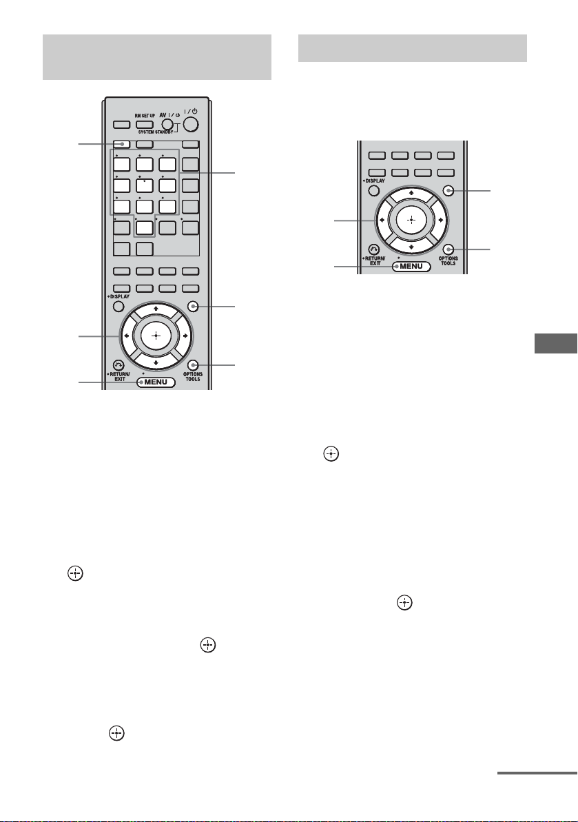
Selecting a channel by inputting
the channel number directly
THEATER
THEATER
BD DVD
BD DVD
MD/
MD/
TAPE
TAPE
MULTI
MULTI
IN
IN
ENT/MEM
ENT/MEM
AMPTV
AMPTV
TV INPUT
TV INPUT
WIDE
WIDE
SA-CD/
SA-CD/
CD
CD
D.TUNING
D.TUNING
DMPORT
DMPORT
CLEAR
CLEAR
HDMI4
HDMI4
MUSICMOVIE
MUSICMOVIE
NIGHT
NIGHT
MODESLEEP
MODESLEEP
GUI
GUI
MODE
MODE
5
SHIFT
SHIFT
5
1
23
1
23
VIDEO2VIDEO1
VIDEO2VIDEO1
456
456
TV
SAT
TV
SAT
789
789
PHONO
TUNER
PHONO
TUNER
-/--
0/10
-/--
0/10
HDMI2HDMI1 HDMI3
HDMI2HDMI1 HDMI3
SIRIUS
SIRIUS
XM
XM
2CH/
2CH/
A.F.D.
A.DIRECT
A.F.D.
A.DIRECT
INPUT
INPUT
MODERESOLUTION
MODERESOLUTION
1
2,
4,6
MENU
HOME
HOME
3
Presetting the channels
You can select the channels you want directly
by presetting them using the preset numbers.
You can preset up to 30 XM Radio channels
and 30 SIRIUS Satellite Radio channels.
2CH/
2CH/
A.F.D.
A.DIRECT
A.F.D.
A.DIRECT
INPUT
INPUT
MODERESOLUTION
MODERESOLUTION
MUSICMOVIE
MUSICMOVIE
NIGHT
NIGHT
MODESLEEP
MODESLEEP
GUI
GUI
MODE
MODE
1
2,
5,6
4
MENU
HOME
HOME
1 Press GUI MODE repeatedly to
select “GUI ON”.
“GUI MODE” appears in the display
window of the receiver and the GUI menu
appears on the TV screen. Press MENU if
the GUI menu does not appear on the TV
screen.
Tuner Operations
1 Press GUI MODE repeatedly to
select “GUI ON”.
“GUI MODE” appears in the display
window of the receiver and the GUI menu
appears on the TV screen. Press MENU if
the GUI menu does not appear on the TV
screen.
2 Press V/v repeatedly to select
“XM” or “SIRIUS”, then press
or b.
3 Press OPTIONS.
4 Press V/v to select “Direct
Tuning”, then press .
5 Press SHIFT, then press the
numeric buttons to enter the
channel number.
6 Press .
The selected channel is tune in.
2 Press V/v repeatedly to select
“XM” or “SIRIUS”, then press
or b.
3 Select a channel you want to
preset using Category Tuning
(page 76) or Direct Tuning
(page 77).
4 Press OPTIONS.
5 Press V/v to select “Memory”,
then press .
continued
77
US
Page 78

6 Press V/v repeatedly to select
the preset channel you want to
use as the preset channel, then
press .
Preset channels from 1 to 30 are available,
and a default channel is preset for all the
preset channels when you purchase the
receiver.
The selected channel is registered as the
preset channel you selected in step 3.
Restricting access to specific
channels (Parental Lock)
(SIRIUS only)
You can restrict access to certain channels
using your own lock code. The lock code is set
to “0000” as the default.
Change the lock code before you use this
function for the first time (see “To change the
lock code”).
7 Repeat steps 3 to 6 to preset
another channel.
To select the preset channels
1
Repeat steps 1 and 2 of “Presetting the
channels”.
2 Press V/v to select the preset number
from the preset list, then press .
You can select stored preset channels from
1 to 30.
Notes
• The channel information you have preset may be
changed if XM Satellite Radio Inc. or SIRIUS
Satellite Radio Inc. change their channel
programming.
• When the “Category Mode” screen is displayed,
press OPTIONS, then press V/v to select “Preset
Mode”.
THEATER
THEATER
6
2,
SHIFT
SHIFT
1
1
VIDEO2VIDEO1
VIDEO2VIDEO1
456
456
TV
SAT
TV
SAT
789
789
PHONO
TUNER
PHONO
TUNER
-/--
0/10
-/--
0/10
HDMI2HDMI1 HDMI3
HDMI2HDMI1 HDMI3
SIRIUS
SIRIUS
XM
XM
2CH/
2CH/
A.F.D.
A.DIRECT
A.F.D.
A.DIRECT
INPUT
INPUT
MODERESOLUTION
MODERESOLUTION
23
23
BD DVD
BD DVD
MD/
MD/
TAPE
TAPE
MULTI
MULTI
IN
IN
ENT/MEM
ENT/MEM
AMPTV
AMPTV
TV INPUT
TV INPUT
WIDE
WIDE
SA-CD/
SA-CD/
CD
CD
D.TUNING
D.TUNING
DMPORT
DMPORT
CLEAR
CLEAR
HDMI4
HDMI4
MUSICMOVIE
MUSICMOVIE
NIGHT
NIGHT
MODESLEEP
MODESLEEP
GUI
GUI
MODE
MODE
6
1
4,5
RETURN/
EXIT O
MENU
HOME
HOME
4
1 Press GUI MODE repeatedly to
select “GUI ON”.
“GUI MODE” appears in the display
window of the receiver and the GUI menu
appears on the TV screen. Press MENU if
the GUI menu does not appear on the TV
screen.
78
2 Press V/v repeatedly to select
“SIRIUS”, then press or b.
3 Select a channel you want to
lock using Category Tuning
(page 76) or Direct Tuning
(page 77).
US
Page 79
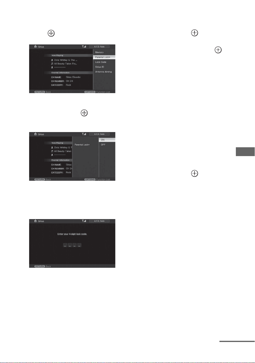
4 Press OPTIONS, then press V/v
to select “Parental Lock”, then
press or b.
5 Press V/v repeatedly to select
“ON”, then press .
“Enter your 4-digit lock code.” appears.
To change the lock code
1
Press V/v repeatedly to select
“SIRIUS”, then press or b.
2 Press OPTIONS, then press V/v to
select “Lock Code”, then press .
“Enter your 4-digit lock code.” appears.
3 Press SHIFT, then press the numeric
buttons to enter your 4-digit lock code.
“Enter a new lock code.” appears.
4 Enter a new 4-digit lock code using the
numeric buttons.
“To confirm, enter your new lock code
again.” appears.
5 Reenter the new lock code with the
numeric buttons.
“The lock code has been changed.”
appears.
6 Press SHIFT, then press the
numeric buttons to enter your
4-digit lock code.
“The channel has been locked.” appears
and the Parental Lock is set.
To delete the numbers you have entered,
go back to step 4 by pressing RETURN/
EXIT O, and then repeat the procedure
above from step 4.
To listen to the locked channels
1
Press V/v repeatedly to select
“SIRIUS”, then press or b.
2 Select a locked channel you want to
listen to using “Direct Tuning”
(page 77).
“The channel is locked. Enter your 4-digit
lock code.” appears.
3 Press SHIFT, then press the numeric
buttons to enter your 4-digit lock code.
The channel is tuned in.
Tuner Operations
continued
79
US
Page 80

To cancel the Parental Lock
1
Press V/v repeatedly to select
“SIRIUS”, then press or b.
2 Tune in the channel you want to unlock
using “Direct Tuning” (page 77).
3 Press OPTIONS, then press V/v to
select “Parental Lock”, then press
or b.
4 Press V/v repeatedly to select “OFF”,
then press .
“Enter your 4-digit lock code.” appears.
5 Press SHIFT, then press the numeric
buttons to enter your 4-digit lock code.
“The channel has been unlocked.” appears
and the channel is unlocked.
Notes
• When you select a channel using Category Tuning,
locked channels are skipped.
• When the receiver is reset to the factory settings,
the lock code returns to the default (0000), but the
Parental Lock settings are not removed.
• You cannot preset locked channels. If you set the
Parental Lock for a preset channel, the preset
information for that channel returns to the default.
• You cannot set the Parental Lock for channel 0 or
channel 184.
80
US
Page 81

XM Radio message list
Message
appears in GUI
menu [Display
window]
Check Antenna
[ANTENNA]
CH Unauthorized
[UNAUTH]
No Signal
[NO SIGNAL]
Loading
[LOADING]
Off Air
[OFF AIR]
[– – – – – – ] No artist name or song title is available
CH Unavailable
[CH UNAVL]
Check XM Tuner
[XM TUNER]
Explanation Remedies
The XM antenna is not connected to the
XM Mini-Tuner and Home Dock or the
XM antenna cable is damaged.
You selected an XM channel that is
blocked or cannot be received with your
XM subscription package.
The XM Mini-Tuner is not receiving the
XM satellite signal. The XM antenna’s
view of the satellites may be blocked or
the antenna is not properly aimed.
The XM Mini-Tuner is acquiring audio
or program information from the XM
satellite signal. This message can also
appear if the signal is too weak.
You selected an XM channel that is not
currently broadcasting.
for this selection.
The selected channel is not available.
The channel may have been reassigned
to a different channel number. This
message may occur initially with a new
radio or a radio that has not received
XM’s signal for an extended period.
The XM Mini-Tuner is not installed or
not fully seated in the XM Mini-Tuner
Home Dock or the XM Mini-Tuner
Home Dock is not connected to the
receiver.
Check that the XM antenna is connected to the
XM Mini-Tuner and Home Dock securely and
check the antenna cable for damage. Replace the
XM antenna if the cable is damaged.
Consult the latest channel guide at
www.xmradio.com for the current list of channels.
For information on receiving this channel, visit
www.xmradio.com or contact XM Satellite Radio
at 1-800-967-2346.
Check the antenna for obstructions and reposition
the XM antenna to get a better signal reception.
To optimize the antenna position, see “Aiming the
XM Antenna or SIRIUS antenna” (page 74).
Refer to the instructions supplied with the XM
Mini-Tuner and Home Dock for antenna
installation information.
This message should disappear in a few seconds
when the signal is strong. If you often see this
message, reposition the XM antenna for better
signal reception.
To optimize the antenna position, see “Aiming the
XM Antenna or SIRIUS antenna” (page 74).
Check this XM channel later. In the meantime,
select another channel.
—
Consult the latest channel guide at
www.xmradio.com for the current list of channels.
For a new radio or a radio that has not received
XM’s signal for an extended period, allow the
radio to receive the XM satellite signal for at least
5 minutes and then select the channel again.
Confirm the XM Mini-Tuner is fully seated in the
dock and check the XM Mini-Tuner and Home
Dock cable is connected to the receiver.
Tuner Operations
continued
81
US
Page 82

SIRIUS Satellite Radio message list
Message
appears in GUI
menu [Display
window]
Antenna Error
[ANTENNA]
Acquiring Signal
[ACQUIRING]
CALL 888-539SIRI [CALL 888,
539-SIRI]
Check Sirius
Tune r
[SR TUNER]
Invalid Channel
[INVALID]
Locked
Channel
[LOCKED CH]
Subscription
Updated
[SUB UPDT]
Updating
Channels
xx%
Completed
(xx are for
integers)
[UPDATING]
Firmware
Updating
[FW UPDT]
[–––– –] There is no text information in the
Explanation Remedies
The antenna is not connected properly. Check the connection between the SiriusConnect
The receiving condition is not good. Try moving the antenna to another location. For
You have not subscribed for the selected
channel.
The SiriusConnect Home tuner is not
connected properly.
You have entered an invalid channel
number.
The selected channel is locked. —
The subscription information has been
updated.
Channel information is being updated. —
The SiriusConnect Home tuner
firmware is being updated.
channel.
Home tuner and the antenna.
details about the antenna location, see the
instructions supplied with the SiriusConnect
Home tuner.
—
Check all the connections, and then turn the
system on again. Also make sure if the AC adaptor
supplied with the SiriusConnect Home tuner is
connected to a wall socket.
The channel to be tuned-in is void due to the
change by the broadcast service, or the receiving
condition is not good.
—
—
This is not an error. The text information may not
be displayed depending on the system condition,
for example, right after the system has received a
channel.
82
US
Page 83

Control for HDMI
Using the Control for HDMI function for “BRAVIA” Sync
To use “BRAVIA” Sync, set the Control for
HDMI function as explained below.
By connecting Sony components that are
compatible with the Control for HDMI
function with an HDMI cable (not supplied),
operation is simplified as follows:
• One-Touch Play: When you play back a
component such as a DVD/Blu-ray disc
player, the receiver and the TV are turned on
automatically and switched to the
appropriate HDMI input.
• System Audio Control: While watching TV,
you can select to output the sound from the
TV speaker or the speakers connected to the
receiver.
• System Power Off: When you turn off the
TV, the receiver and connected components
are also turned off simultaneously.
The Control for HDMI function
does not work in the following
cases:
• When you connect the receiver to a
component which does not correspond with
Sony Control for HDMI function.
• When you connect the receiver and
components using other than HDMI
connection.
We recommend that you connect the receiver
to products featuring “BRAVIA” Sync.
Note
Depending on the connected component, the
Control for HDMI function may not work. Refer to
the operating instructions of the component.
Control for HDMI
Control for HDMI is a mutual control function
standard used by HDMI CEC (Consumer
Electronics Control) for HDMI (HighDefinition Multimedia Interface).
83
US
Page 84

Connecting a TV and other
components
Before connecting the cords, be sure to
disconnect the AC power cord.
To enjoy TV multi channel
surround sound broadcasting
You can listen to TV multi channel surround
sound broadcasting from the speakers
connected to the receiver.
Connect the OPTICAL output jack of the TV
to the OPTICAL IN jack of the receiver.
Satellite tuner, Set-top box Blu-ray disc player
Audio/video
signals
Audio/video
signals
AAA
ACB
DVD playe r
Audio/video
signals
Audio signals
TV, etc.
A HDMI cable (not supplied)
We recommend that you use a Sony HDMI cable.
B Optical digital cord (not supplied)
C Audio cord (not supplied)
a)
Connect at least one of the audio cords (B or C).
US
84
a)
a)
Audio/video
signals
Page 85

Preparing Control for HDMI function
This receiver supports the Control for HDMIEasy Setting function.
This function is only available for certain
types of TV. When you perform the Control
for HDMI-Easy Setting on the TV, the Control
for HDMI setting on this receiver will
automatically change accordingly.
During the Control for HDMI-Easy Setting
operation, “SCANNING” flashes in the
display window. This receiver will
automatically change the input to HDMI input.
When the setting is completed,
“COMPLETE” appears on the display
window.
For details, refer to the operating instructions
of the TV.
If your TV does not support the Control for
HDMI-Easy Setting function, do the following
procedures. For details on setting the TV and
the connected components, refer to the
operating instructions of the respective
components.
1 Make sure that the receiver is connected to
the TV and components (compatible with
Control for HDMI function) via HDMI
connection.
2 Turn on the receiver, TV and connected
components.
3 Set the respective Control for HDMI
function for the receiver and TV to on.
See “To set Control for HDMI” (page 86).
When the receiver menu is displayed on the
TV screen in the screen mode, press GUI
MODE repeatedly to select “GUI OFF” to
enter the display mode, then check the TV
display image of the component connected
to the receiver.
For details on setting the TV, refer to the
operating instructions of the TV.
4 Select the HDMI input of the receiver and
TV to match the HDMI input of the
connected component, so that the image
from the connected component is displayed.
5 Set the Control for HDMI function for the
connected component to on.
If the Control for HDMI function for the
connected component is already set to on,
you do not need to change the setting.
6 Repeat steps 4 and 5 for other components
that you want to use the Control for HDMI
function.
Notes
• If you unplug and reconnect the HDMI cable, be
sure to repeat steps 1 to 6 above.
• You cannot perform One-Touch Play and System
Audio Control during the Control for HDMI-Easy
Setting operation.
• Before you do the Control for HDMI-Easy Setting
from the TV, be sure to turn on the TV, connected
components and receiver.
• If the playback components cannot function after
you have made the settings for Control for HDMIEasy Setting, check the Control for HDMI setting
on your TV.
• If the connected components do not support the
Control for HDMI-Easy Setting, you need to set
the Control for HDMI function for the connected
components to on before you perform the Control
for HDMI-Easy Setting from the TV.
Control for HDMI
85
US
Page 86

To set Control for HDMI
2CH/
2CH/
A.F.D.
A.DIRECT
A.F.D.
A.DIRECT
INPUT
INPUT
MODERESOLUTION
MODERESOLUTION
MUSICMOVIE
MUSICMOVIE
NIGHT
NIGHT
MODESLEEP
MODESLEEP
MODE
MODE
GUI
GUI
1
2-5
HOME
HOME
MENU
1 Press GUI MODE repeatedly to
select “GUI ON”.
“GUI MODE” appears in the display
window of the receiver and the GUI menu
appears on the TV screen. Press MENU if
the GUI menu does not appear on the TV
screen.
2 Press V/v repeatedly to select
“Settings”, then press or b.
The Settings menu list appears on the TV
screen.
3 Press V/v repeatedly to select
“HDMI”, then press or b.
Watching a DVD
(One-Touch Play)
You can enjoy sound and image from the
components connected to the receiver via
HDMI connections by a simple operation.
Play back a connected component.
The receiver and the TV are turned on
automatically and switched to the appropriate
HDMI input.
Watching a DVD by simple
operation
You can also select a connected component,
such as a DVD/Blu-ray disc player using the
TV menu. In this case, the receiver and the TV
switch to the appropriate HDMI input.
Note
Depending on the TV, the start of the content may
not be output.
4 Press V/v repeatedly to select
“Control for HDMI”, then press
.
5 Press V/v repeatedly to select
“ON”, then press .
Control for HDMI function is activated.
US
86
Page 87

Enjoying the TV sound
from the speakers
connected to the receiver
(System Audio Control)
You can enjoy the TV sound from the speakers
connected to the receiver by a simple
operation.
You can operate System Audio Control
function using the TV menu. For details, refer
to the operating instructions of the TV.
When System Audio Control function is
turned on, the receiver will turns on and
switches to the appropriate input
automatically.
TV sound is output from the speakers
connected to the receiver, and the volume of
the TV is minimized simultaneously.
You can also use the System Audio Control
function as follows.
• If you turn on the receiver while the TV is
turned on, the System Audio Control
function will automatically be set to on and
the TV sound will output from the speakers
connected to the receiver. However, if you
turn off the receiver, the sound will output
from the TV speakers.
• You can adjust the receiver’s volume when
you adjust the TV volume.
Notes
• If System Audio Control does not function
according to your TV setting, refer to the operating
instructions of the TV.
• When “Control for HDMI” is set to “ON”, the
“Audio Out” settings in the HDMI settings menu
will be set automatically depending on the System
Audio Control settings.
• When you connect a TV that does not have System
Audio Control function, the System Audio Control
function does not work.
• If the TV is turned on before turning on the
receiver, the TV sound will not be output for a
moment.
Control for HDMI
87
US
Page 88

Turning off the receiver
with the TV
(System Power Off)
When you turn the TV off by using the
POWER button on the TV’s remote, the
receiver and the connected components turn
off automatically.
You can also use the receiver’s remote to turn
off the TV.
THEATER
THEATER
AV ?/1
TV
SHIFT
SHIFT
1
1
VIDEO2VIDEO1
VIDEO2VIDEO1
2 3
2 3
AMPTV
AMPTV
TV INPUT
TV INPUT
BD DVD
BD DVD
Press TV, then press AV ?/1.
The TV, receiver and the components
connected via HDMI are turned off.
Notes
• Set the TV Standby Synchro to “ON” before using
the System Power Off function. For details, refer to
the operating instructions of the TV.
• Depending on the status, the connected
components may not be turned off. For details,
refer to the operating instructions of the connected
components.
Other Operations
Converting analog video input signals
This receiver allows you to convert the
resolution of analog video input signals.
2CH/
2CH/
A.F.D.
A.DIRECT
A.F.D.
A.DIRECT
INPUT
INPUT
MODERESOLUTION
RESOLUTION
MODERESOLUTION
Press RESOLUTION repeatedly.
Each time you press the button, the resolution
of the output signals will be changed.
You can also use “Resolution” in the Video
settings menu.
HOME
HOME
MUSICMOVIE
MUSICMOVIE
NIGHT
NIGHT
MODESLEEP
MODESLEEP
GUI
GUI
MODE
MODE
88
US
Page 89

Enjoying the sound/ images from the components connected to the DIGITAL MEDIA PORT
The DIGITAL MEDIA PORT (DMPORT)
allows you to enjoy sound from a network
system such as a portable audio/video source
or computer.
By connecting a DIGITAL MEDIA PORT
adapter, you can enjoy sound and image from
the connected component on the receiver.
For details on connecting the DIGITAL
MEDIA PORT adapter, see “Connecting
components with digital audio input/output
jacks” (page 19).
Sony offers the following DIGITAL MEDIA
PORT adapters:
• TDM-BT1 Bluetooth™ Wireless Audio
Adapter
• TDM-NW1/NW10 DIGITAL MEDIA
PORT Adapter
• TDM-NC1 Wireless Network Audio Client
• TDM-iP1/iP10/iP50 DIGITAL MEDIA
PORT Adapter
• TDM-MP10 DIGITAL MEDIA PORT
Adapter
The DIGITAL MEDIA PORT adapter is an
optional product.
Notes
• Do not connect an adapter other than the DIGITAL
MEDIA PORT adapter.
• Before disconnecting the DIGITAL MEDIA PORT
adapter, make sure to turn the receiver off using the
remote.
• Do not connect or disconnect the DIGITAL
MEDIA PORT adapter to/from the receiver while
the system is turned on.
• Depending on the type of DIGITAL MEDIA
PORT adapter, the images are also output.
• The DIGITAL MEDIA PORT adapters are
available for purchase depending on the area.
Selecting an operation screen
to operate the component
connected to the DIGITAL MEDIA
PORT adapter
You can select an operation screen using the
GUI menu, depending on the DIGITAL
MEDIA PORT adapter you want to use. For
some adapter, such as TDM-BT1 or TDMNW1, the operation screen is fixed and you
cannot change it on the GUI screen.
2CH/
2CH/
A.F.D.
A.DIRECT
A.F.D.
A.DIRECT
INPUT
INPUT
MODERESOLUTION
MODERESOLUTION
MUSICMOVIE
MUSICMOVIE
NIGHT
NIGHT
MODESLEEP
MODESLEEP
GUI
GUI
MODE
MODE
1
2,
3,5
MENU
HOME
HOME
4
1 Press GUI MODE repeatedly to
select “GUI ON”.
“GUI MODE” appears in the display
window of the receiver and the GUI menu
appears on the TV screen. Press MENU if
the GUI menu does not appear on the TV
screen.
2 Press V/v repeatedly to select
“Music”, then press or b.
“DMPORT” appears beside “Music”.
Other Operations
continued
89
US
Page 90
3 Press or b.
The component connected to the
DIGITAL MEDIA PORT adapter is
recognized and “DMPORT” on the TV
screen will change to the component’s
name.
The category of the component connected
to DIGITAL MEDIA PORT adapter
appears on the TV screen.
Note
An icon which shows the component
recognized is displayed on the TV screen. If
the component connected to the adapter cannot
be recognized, “DMPORT” is displayed on the
TV screen.
Operating the component
connected to the DIGITAL MEDIA
PORT adapter
To operate the TDM-iP1/TDMiP50/TDM-NC1 using the GUI
menu of the receiver
1 Make sure that “System GUI” is
selected in step 5 in “Selecting
an operation screen to operate
the component connected to
the DIGITAL MEDIA PORT
adapter” (page 89).
4 Press OPTIONS to display
“Function List”.
5 Press V/v to select “DMPORT
Control”, then press or b.
You can select the following modes in this
menu:
• System GUI
This mode is for the TDM-iP1 and
TDM-NC1. The list of tracks will be
displayed on the GUI screen of the
receiver. You can select a track you want
and play it back on each GUI screen.
• Adapter GUI
This mode is for the TDM-iP1 and
TDM-NC1. The menu of the adapter
will be displayed on the TV screen.
•iPod
This mode can be selected only when
the TDM-iP1 is connected.
If “DMPORT Control” is not displayed,
refer to the operating instructions
supplied with component for details on
operating that component.
2 Select the content from the
contents list displayed on the
GUI screen and play it back.
In case of iPod
Music Playlists > Playlist > Track
Artists > Artist > Album > Track
Albums > Album > Track
Songs > Track
Genres > Genre > Artist > Album > Track
Composers > Composer > Album > Track
Audiobooks > Track
Video Movies > Content
TV Shows > Episode > Content
Music Videos > Artist > Content
Video Playlists > Video Playlist > Content
Video Podcast > Episode > Content
In case of Network Client
Music Surfin
a)
> Albumc) > Track
a)
Playlist
> Playlist > Track
Web Radio
Music Library
a)
> Station > Program
b)
> Album > Track
90
a)
Displayed only when M-crew Server is connected.
b)
Displayed only when a DLNA server other than
M-crew Server is connected.
c)
Displayed as “Genre”, “Artist” or “Album”,
depending on the “List Mode” setting.
US
Page 91

To operate the TDM-iP1/iP50 or
TDM-NC1 using the adapter
menu
Make sure that “Adapter GUI” is selected in
step 5 in “Selecting an operation screen to
operate the component connected to the
DIGITAL MEDIA PORT adapter” (page 89).
For details on operating the adapter using the
adapter GUI menu, refer to the operating
instructions supplied with the adapter you are
using.
To operate the TDM-iP1/iP50
using the iPod menu
Make sure that “iPod” is selected in step 5 in
“Selecting an operation screen to operate the
component connected to the DIGITAL
MEDIA PORT adapter” (page 89).
For details on operating the iPod, refer to the
operating instruction supplied with the iPod.
Playing back the track selected
During playback of the selected track, the
displayed screen changes depending on the
DIGITAL MEDIA PORT adapter connected.
TDM-iP1
You can also operate the components
connected to the DIGITAL MEDIA PORT
adapter using the following play mode buttons
on the remote of the receiver.
Press DMPORT on the remote to enable
DMPORT operation.
To Do the following
Play Press N.
Pause Press X. To resume play,
Stop Press x.*
Find the beginning of a
track during playback, or
find the beginning of the
previous track
Find the beginning of the
next track
Skip to the previous
album
Skip to the next album Press •b.
Go backward/forward Press m/M.**
* When a TDM-iP1 is connected, the receiver
enters pause mode when x is pressed.
** Fast-backward/forward while pressing and
holding the m/M button.
press the button again.
Press ..
Press >.
Press B•.
Option parameters in the play
modes
Other Operations
TDM-NC1
x Repeat Mode (TDM-iP1/iP50
only)
Plays one or all the track repeatedly.
•Off
Deactivates the repeat play mode.
•One
Plays one track repeatedly.
•All
Plays all the tracks repeatedly.
continued
91
US
Page 92

x Shuffle (TDM-iP1 only)
Plays all the tracks in random order.
•Off
Deactivates the shuffle play mode.
• Albums
Plays all the tracks on an album in random
order.
• Songs
Plays all the tracks in “Songs” in random
order.
x List Mode (TDM-NC1 only)
Selects a range of tracks to be played back.
•Genre
Plays back tracks in the selected genre.
• Artist
Plays back tracks of the selected artist.
• Album
Plays back tracks in the selected album.
Tip
The List Mode can be used with the Function List
menu even when the list is displayed.
DIGITAL MEDIA PORT message
list
Message appears Explanation
No Adapter The adapter is not connected.
No Device There is no device connected
No Audio No audio file was found.
Loading The data is being read.
No Server* There is no server connected.
No Track* No track was found.
No Item* No item was found.
Connecting* Connecting to the server.
Configuring* The network is setting up.
Warning* Check the adapter display of
Party Mode* The unit is currently in party
Searching* Searching the server.
*TDM-NC1 only.
US
92
to the adapter.
the DIGITAL MEDIA PORT
adapter.
mode “Guest”.
Naming inputs
You can enter a name of up to 8 characters for
inputs and display it.
This is convenient for labeling the jacks with
the names of the connected components.
2CH/
2CH/
A.F.D.
A.DIRECT
A.F.D.
A.DIRECT
INPUT
INPUT
MODERESOLUTION
MODERESOLUTION
MUSICMOVIE
MUSICMOVIE
NIGHT
NIGHT
MODESLEEP
MODESLEEP
GUI
GUI
MODE
MODE
3-4
HOME
HOME
2
1 Choose the item you want to
name.
You can name the following items.
• Auto Calibration position (page 47)
• Inputs (page 47)
• Preset stations (page 71)
2 Press OPTIONS.
3 Select “Name Input”, then
press .
The soft keyboard appears on the screen.
4 Press V/v/B/b to select a
character, then press .
5 Select [Finish] to enter the
name.
The name you entered is registered.
To cancel naming input
Select [Cancel].
Page 93

Switching between
digital and analog audio
(INPUT MODE)
When you connect components to both digital
and analog audio input jacks on the receiver,
you can fix the audio input mode to either of
them, or switch from one to the other,
depending on the type of material you intend
to watch.
THEATER
THEATER
BD DVD
BD DVD
MD/
MD/
TAPE
TAPE
MULTI
MULTI
IN
IN
ENT/MEM
ENT/MEM
AMPTV
AMPTV
TV INPUT
TV INPUT
WIDE
WIDE
SA-CD/
SA-CD/
CD
CD
D.TUNING
D.TUNING
DMPORT
DMPORT
CLEAR
CLEAR
HDMI4
HDMI4
MUSICMOVIE
MUSICMOVIE
NIGHT
NIGHT
MODESLEEP
MODESLEEP
GUI
GUI
MODE
MODE
1
SHIFT
SHIFT
1
23
1
23
VIDEO2VIDEO1
VIDEO2VIDEO1
456
456
TV
SAT
TV
SAT
789
789
PHONO
TUNER
PHONO
TUNER
-/--
0/10
-/--
0/10
HDMI2HDMI1 HDMI3
HDMI2HDMI1 HDMI3
SIRIUS
SIRIUS
XM
XM
2CH/
2CH/
A.F.D.
A.DIRECT
A.F.D.
A.DIRECT
INPUT
INPUT
MODERESOLUTION
MODERESOLUTION
2
Audio input modes
•AUTO
Gives priority to digital audio signals when
there are both digital and analog
connections. If there are more than one
digital connection, HDMI audio signals have
priority over COAXIAL and OPTICAL
audio signals.
If there are no digital audio signals, analog
audio signals are selected.
•ANALOG
Specifies the analog audio signals input to
the AUDIO IN (L/R) jacks.
Notes
• Some audio input modes may not be set up
depending on the input.
• When HDMI input, XM, SIRIUS or DMPORT input
is selected, “------” appears on the display window,
and you cannot select other audio input modes.
Select an input other than the HDMI input, XM,
SIRIUS and DMPORT input, then set the audio input
mode.
• When “2ch Analog Direct” is being used, or the
multi channel input is selected, audio input mode is
set to “ANALOG”. You cannot select other audio
input modes.
HOME
HOME
1 Press the input button.
You can also use INPUT SELECTOR on
the receiver.
2 Press INPUT MODE repeatedly
to select the audio input mode.
The selected audio input mode appears on
the TV screen.
93
Other Operations
US
Page 94

Enjoying the sound/ images from other inputs
You can reassign video and/or audio signals to
another input.
Example: Connect the OPTICAL OUT jack of
the DVD player to the OPTICAL VIDEO 1 IN
jack of this receiver when you want to input
only the digital optical audio signals from the
DVD player.
Connect the component video jack of the DVD
player to the COMPONENT VIDEO COMPO
1 IN jack of this receiver when you want to
input the video signals from the DVD player.
Assign video and/or audio signals to the DVD
input jack using “Input Assign” in the Input
menu.
2CH/
2CH/
A.F.D.
A.DIRECT
A.F.D.
A.DIRECT
INPUT
INPUT
MODERESOLUTION
MODERESOLUTION
MUSICMOVIE
MUSICMOVIE
NIGHT
NIGHT
MODESLEEP
MODESLEEP
GUI
GUI
MODE
MODE
1
2,
3,5
2 Press V/v repeatedly to select
“Input”, then press or b.
3 Press V/v to select the input
name you want to assign.
4 Press OPTIONS, then select
“Input Assign”.
MENU
6
HOME
HOME
4
1 Press GUI MODE repeatedly to
select “GUI ON”.
“GUI MODE” appears in the display
window of the receiver and the GUI menu
appears on the TV screen. Press MENU if
the GUI menu does not appear on the TV
screen.
US
94
5 Select the audio and/or video
signals you want to assign to
the input which you selected in
step 3 using V/v/B/b, then
press .
6 Press RETURN/EXIT O to
enter the setting.
Page 95

Input name
VIDEO1 VIDEO2
BD DVD SAT MD/TAPE SA-CD/CDMULTI IN
Assignable video
input jacks
Assignable audio
input jacks
Vid eo1 :
Composite
Vid eo2 :
Composite
BD:
Composite
DVD:
Composite
SAT:
Composite
HDMI1 aaaaaa a a
HDMI2 aaaaaa a a
HDMI3 aaaaaa a a
HDMI4 aaaaaa a a
Component1 aaaaaa a a
Component2 aaaaaa a a
Component3 aaaaaa a a
None aaaaa a a a
Vid eo1 : OPT a – aaa – a –
Vid eo2 : OPT – aaaa – a –
MD/TAPE:
OPT
BD: COAX aaa– aa ––
DVD: COAX aa – aa a ––
SA-CD/CD:
COAX
Analog aaaaaa a –
a –––– – – –
– a ––– – – –
––a –– – – –
–––a ––––
––––a –––
––aaaa a –
aa ––aaa –
Other Operations
Notes
• You cannot assign optical signals from an input source to the optical input jacks on the receiver, and you
cannot assign coaxial signals from the input source to the coaxial input jacks on the receiver.
• When you assign the digital audio input, the INPUT MODE setting may change automatically.
95
US
Page 96

Changing the display window
You can check the sound field, etc., by
changing the information on the display
window.
2CH/
2CH/
A.F.D.
A.DIRECT
A.F.D.
A.DIRECT
INPUT
INPUT
MODERESOLUTION
MODERESOLUTION
DISPLAY GUI
Press DISPLAY repeatedly.
Each time you press DISPLAY, the display
will change as follows.
Input name you selected
name t Sound field type t Volume level t
Stream information
Tip
You cannot switch the display while “GUI MODE”
is shown on the display window. Press GUI MODE
repeatedly to select “GUI OFF”.
MUSICMOVIE
MUSICMOVIE
NIGHT
NIGHT
MODESLEEP
MODESLEEP
GUI
GUI
MODE
MODE
HOME
HOME
* t Original input
MODE
FM and AM band
Station name* t Frequency t Sound field
type t Volume level
XM Radio and SIRIUS Satellite
Radio
Channel name t Channel number t
Category name t Artist name/Feature t
Song/program title t Composer name
(SIRIUS only) t Signal strength t Sound
field type t Volume level
* Index name appears only when you have assigned
one to the input or preset station. Index name does
not appear when only blank spaces have been
entered.
Note
Character or marks may not be displayed for some
languages.
96
US
Page 97

About the indicators on the display window
SW
LFE
L
CR
SLSSR
SB LSBSB R
OPT D +EX
MULTI IN
HDMI
DTS - HD
DMPORT ANALOG LPCM
TrueHDNeural
MSTR HI
RES NEO:6
COAX
Name Function
A SW Lights up when subwoofer
is connected and the audio
signal is output from the
SUBWOOFER jack. While
this indicator lights up, the
receiver creates a
subwoofer signal based on
the LFE signal in the disc
being played back or the
low frequency components
of the front channels.
B LFE Lights up when the disc
being played back contains
an LFE (Low Frequency
Effects) channel and the
LFE channel signal is
actually being reproduced.
C COAX Lights up when INPUT
MODE is set to “AUTO”
and the source signal is a
digital signal being input
through the COAXIAL
jack.
D OPT Lights up when INPUT
MODE is set to “AUTO”
and the source signal is a
digital signal being input
through the OPTICAL jack.
--
THX DTS D.RANGE CAT B SLEEP
EQ-Bl
96 24
PL ll
AMP
/
MEM MONO ST
X
XM
SIRIUS A.DIRECT
+
ASPES
Name Function
E ; D/
; D EX/
; D+/
; TrueHD
“; D” lights up when the
receiver is decoding Dolby
Digital signals.
“; D EX” lights up when
the receiver is decoding
Dolby Digital Surround EX
signals.
“; D+” lights up when the
receiver is decoding Dolby
Digital Plus signals.
“; TrueHD” lights up
when the receiver is
decoding Dolby TrueHD
signals.
Note
When playing a Dolby Digital
format disc, be sure that you
have made digital connections
and that INPUT MODE is set
to “AUTO” (page 93).
F Neural-THX Lights up when the receiver
applies Neural-THX
processing to input signals.
Other Operations
continued
97
US
Page 98

Name Function
G DTS/
DTS-ES/
DTS 96/24
“DTS” lights up when the
receiver is decoding DTS
signals.
“DTS-ES” lights up when
the receiver is decoding
DTS-ES signals.
“DTS 96/24” lights up
when the receiver is
decoding DTS 96 kHz/24
bit signals.
Note
When playing a DTS format
disc, be sure that you have
made digital connections and
that INPUT MODE is set to
“AUTO” (page 93).
H D.RANGE Lights up when dynamic
range compression is
activated.
I CAT Lights up when category
mode is selected during
satellite radio operation.
J SP A/SP B/
SP A+B
Lights up according to the
speaker system used
(page 40). However, these
indicators do not light up if
the speaker output is turned
off or if headphones are
connected.
K SLEEP Lights up when the sleep
timer is activated.
L A.DIRECT Lights up when the receiver
is processing Analog Direct
signals.
M Tuner
indicators
Lights up when using the
receiver to tune in radio
stations, etc.
N SIRIUS Lights up when
SiriusConnect Home tuner
is connected and “SIRIUS”
is selected.
O MEM Lights up when a memory
function, such as Name
Input etc., is activated.
Name Function
P XM Lights up when XM Mini-
Tuner and Home Dock are
connected and “XM
RADIO” is selected.
Q ; PL/
; PL II/
; PL IIx
“; PL” lights up when the
receiver applies Dolby Pro
Logic processing to 2
channel signals in order to
output the center and
surround channel signals.
“; PL II” lights up when
the Dolby Pro Logic II
decoder is activated.
“; PL IIx” lights up when
the Dolby Pro Logic IIx
decoder is activated.
However, these indicators
do not light up if there are
no center and surround
speakers and you select a
sound field using the A.F.D.
button.
R BI-AMP Lights up when “Sur Back
Assign” is set to “BIAMP”.
S EQ Lights up when the
equalizer is activated.
T NEO:6 Lights up when DTS Neo:6
Cinema/Music decoding is
activated.
U DTS-HD
MSTR/
DTS-HD HI
RES/
“DTS-HD MSTR” lights up
when the receiver is
decoding DTS-HD Master
Audio signals.
“DTS-HD HI RES” lights
up when the receiver is
decoding DTS-HD High
Resolution signals.
V LPCM Lights up when Linear
PCM signals are detected.
98
US
Page 99

Name Function
W ANALOG Lights up when
– INPUT MODE is set to
“AUTO” and no digital
signal is being input
through the COAXIAL,
OPTICAL or HDMI
jacks.
– INPUT MODE is set to
“ANALOG”.
– the “2ch Analog Direct”
is being used.
X DMPORT Lights up when DIGITAL
MEDIA PORT adapter is
connected and “DMPORT”
is selected.
Y MULTI IN Lights up when multi
channel input is selected.
Z HDMI Lights up when the receiver
recognizes a component
connected via an HDMI IN
jack.
Name Function
wj Playback
channel
indicators
The letters (L, C, R, etc.)
indicate the channels being
played back. The boxes
around the letters vary to
show how the receiver
downmixes the source
sound (based on the speaker
settings).
L
R
C
SL
SR
S
Front Left
Front Right
Center (monaural)
Surround Left
Surround Right
Surround (monaural or the
surround components
obtained by Pro Logic
processing)
SBL
SBR
SB
Surround Back Left
Surround Back Right
Surround Back (the
surround back components
obtained by 6.1 channel
decoding)
Example:
Recording format (Front/
Surround): 3/2.1
Output channel: When
“Speaker Pattern” is set to
“3/0.1” (page 65).
Sound Field: A.F.D. AUTO
Other Operations
SW
L
CR
SL SR
99
US
Page 100

Using the sleep timer
Recording using the
You can set the receiver to turn off
automatically at a specified time.
2CH/
2CH/
A.DIRECT
A.DIRECT
A.F.D.
A.F.D.
INPUT
INPUT
MODERESOLUTION
MODERESOLUTION
MUSICMOVIE
MUSICMOVIE
NIGHT
NIGHT
MODESLEEP
MODESLEEP
SLEEP
Press SLEEP repeatedly.
Each time you press SLEEP, the display
changes cyclically as follows:
When sleep timer is being used, “SLEEP”
lights up in the display window.
Tip
To check the remaining time before the receiver
turns off, press SLEEP. The remaining time appears
on the display window. If you press SLEEP again,
the sleep timer will be cancelled.
receiver
You can record from a video/audio component
using the receiver. Refer to the operating
instructions supplied with your recording
component.
THEATER
THEATER
BD DVD
BD DVD
MD/
MD/
TAPE
TAPE
MULTI
MULTI
IN
IN
ENT/MEM
ENT/MEM
AMPTV
AMPTV
TV INPUT
TV INPUT
WIDE
WIDE
SA-CD/
SA-CD/
CD
CD
D.TUNING
D.TUNING
DMPORT
DMPORT
CLEAR
CLEAR
MUSICMOVIE
MUSICMOVIE
1
SHIFT
SHIFT
1
23
1
23
VIDEO2VIDEO1
VIDEO2VIDEO1
456
456
TV
SAT
TV
SAT
789
789
PHONO
TUNER
PHONO
TUNER
-/--
0/10
-/--
0/10
HDMI2HDMI1 HDMI3 HDMI4
HDMI2HDMI1 HDMI3 HDMI4
SIRIUS
SIRIUS
XM
XM
2CH/
2CH/
A.F.D.
A.DIRECT
A.F.D.
A.DIRECT
Recording onto a MiniDisc or
audio tape
You can record onto a MiniDisc or audio tape
using the receiver. Refer to the operating
instructions supplied with your MD deck or
tape deck.
100
1 Press the input button of the
playback component.
You can also use INPUT SELECTOR on
the receiver.
2 Prepare the playback
component for playing.
For example, insert a CD into the CD
player.
US
 Loading...