

Sony STR-DE998 User Manual

2-580-804-11(1)
FM Stereo
FM/AM Receiver
Operating Instructions
Owner’s Record
The model and serial numbers are located on the rear of the unit. Record the serial
number in the space provided below. Refer to them whenever you call upon your
Sony dealer regarding this product.
Model No.
Serial No.
STR-DE998
©2005 Sony Corporation
WARNING
To prevent fire or shock hazard, do not
expose the unit to rain or moisture.
To prevent fire, do not cover the ventilation of the
apparatus with newspapers, table-cloths, curtains, etc.
And don’t place lighted candles on the apparatus.
To prevent fire or shock hazard, do not place objects
filled with liquids, such as vases, on the apparatus.
Do not install the appliance in a confined space,
such as a bookcase or built-in cabinet.
Don’t throw away batteries with
general house waste; dispose of
them correctly as chemical waste.
For customers in the United States
This symbol is intended to alert
the user to the presence of
uninsulated “dangerous voltage”
within the product’s enclosure
that may be of sufficient
magnitude to constitute a risk of
electric shock to persons.
This symbol is intended to alert
the user to the presence of
important operating and
maintenance (servicing)
instructions in the literature
accompanying the appliance.
WARNING
This equipment has been tested and found to comply
with the limits for a Class B digital device, pursuant to
Part 15 of the FCC Rules. These limits are designed to
provide reasonable protection against harmful
interference in a residential installation. This
equipment generates, uses, and can radiate radio
frequency energy and, if not installed and used in
accordance with the instructions, may cause harmful
interference to radio communications. However, there
is no guarantee that interference will not occur in a
particular installation. If this equipment does cause
harmful interference to radio or television reception,
which can be determined by turning the equipment off
and on, the user is encouraged to try to correct the
interference by one or more of the following measures:
– Reorient or relocate the receiving antenna.
– Increase the separation between the equipment and
receiver.
– Connect the equipment into an outlet on a circuit
different from that to which the receiver is
connected.
– Consult the dealer or an experienced radio/TV
technician for help.
CAUTION
You are cautioned that any changes or modification not
expressly approved in this manual could void your
authority to operate this equipment.
Note to CATV system installer:
This reminder is provided to call CATV system
installer’s attention to Article 820-40 of the NEC that
provides guidelines for proper grounding and, in
particular, specifies that the cable ground shall be
connected to the grounding system of the building, as
close to the point of cable entry as practical.
For customers in Canada
CAUTION
TO PREVENT ELECTRIC SHOCK, MATCH WIDE
BLADE OF PLUG TO WIDE SLOT, FULLY
INSERT.
NERGY STAR
E
mark. As an E
Sony Corporation has determined that
this product meets the E
®
is a U.S. registered
NERGY STAR
NERGY STAR
®
partner,
®
guidelines for energy efficiency.
US
2
About This Manual
• The instructions in this manual is for model
STR-DE998. Check your model number by looking
at the lower right corner of the front panel.
• The instructions in this manual describe the controls
on the receiver. You can use the controls on the
supplied remote if they have the same or similar
names as those on the receiver. For details on the use
of your remote, see pages 45–55.
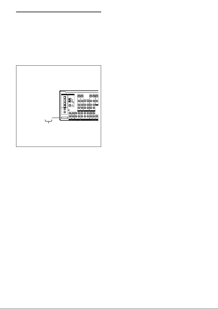
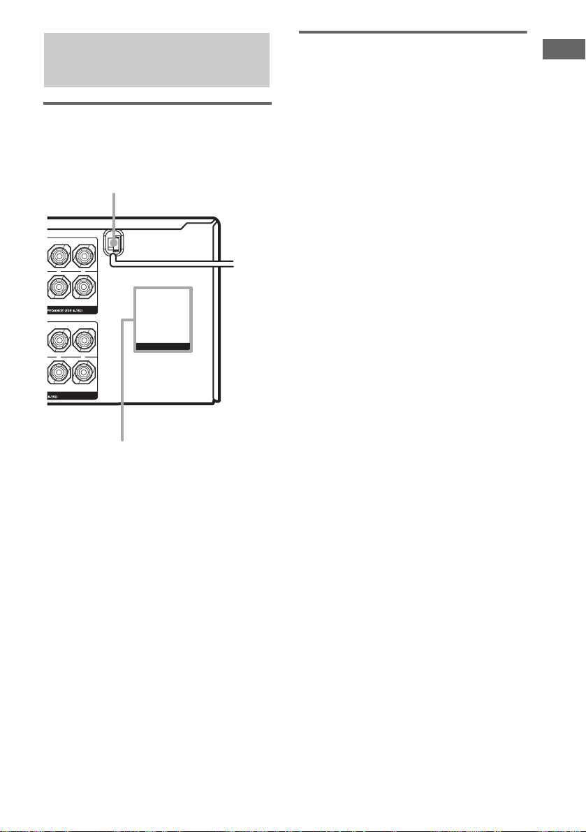
About area codes
The area code of the receiver you purchased is
shown on the lower portion of the rear panel (see
the illustration below).
DIGITAL
ANTENNA
OPTICAL
TV/SAT
IN
MD/
TAPE
IN
MD/
TAPE
OUT
SA-CD/
CD
IN
DVD
IN
SA-CD/
CD
IN
COAXIAL
ASSIGNABLE
2-XXX-XXX-XX AA
(INPUT ONLY)
Area code
Any differences in operation, according to the area
code, are clearly indicated in the text, for example,
“Models of area code AA only”.
This receiver incorporates Dolby* Digital and Pro
Logic Surround and the DTS** Digital Surround
System.
* Manufactured under license from Dolby
Laboratories.
“Dolby”, “Pro Logic” and the double-D symbol are
trademarks of Dolby Laboratories.
** “DTS”, “DTS-ES”, “Neo:6” and “DTS 96/24” are
trademarks of Digital Theater Systems, Inc.
SIGNAL GND
S-VIDEO
IN
VIDEO IN
VIDEO OUT
AUDIO IN
AUDIO OUT
DVD VIDEO 2
LRL
FRONT SURROUND
MULTI CH IN
S-VIDEO
S-VIDEO
S-VIDEO
OUT
OUT
IN
VIDEO IN
VIDEO OUT
VIDEO OUTVIDEO IN
L
MONITOR
R
AUDIO IN
AUDIO OUT
AUDIO IN
VIDEO 1
CENTER
L
R
R
SURR
SUB
SUB
OUT
BACK
WOOFER
WOOFER
2ND ZONE
PRE OUT
S-VIDEO
IN
AM
VIDEO IN
LRL
R
AUDIO IN
TV/SAT
LRL
R
OUT ININ IN
MD/TAPE
PHONO
SA-CD/CD
US
3

Table of Contents
Getting Started
1: Check how to hookup your
components.......................................5
1a: Connecting components with
digital audio output jacks ...........7
1b: Connecting components with
multi channel output jacks........10
1c: Connecting components with
only analog audio jacks............12
2: Connecting the antennas ...................14
3: Connecting speakers .........................15
4: Connecting the AC power cord ........ 17
5: Setting up the speakers .....................18
6: Adjusting the speaker levels and
balance............................................22
— TEST TONE
Amplifier Operation
Selecting the component.......................23
Listening to multi channel sound..........24
— MULTI CH IN
Listening to FM/AM radio....................24
Presetting radio stations ........................25
Changing the display.............................26
About the indications in the display......27
Enjoying Surround Sound
Using only the front speakers ...............29
Enjoying higher fidelity sound..............30
— AUTO FORMAT DIRECT
Selecting a sound field..........................31
Selecting the surround back decoding
mode ...............................................33
— SURR BACK DECODING
Advanced Adjustments and
Settings
Reassigning the digital audio input ...... 35
— DIGITAL ASSIGN
Reassigning the component video
input................................................ 36
— COMPONENT VIDEO
INPUT ASSIGN
Switching the audio input mode for
digital components ......................... 36
— INPUT MODE
Customizing sound fields ..................... 37
Adjusting the equalizer......................... 38
Advanced settings................................. 39
Other Operations
Naming preset stations and inputs........ 41
Using the Sleep Timer .......................... 41
Selecting the speaker system................ 42
Recording ............................................. 42
Listening to the sound in another
zone ................................................ 43
Operations Using the Remote
RM-AAE001
Before you use your remote.................. 45
Remote button description.................... 45
Selecting the command mode of the
remote............................................. 50
Programming the remote...................... 50
Learning the commands of your
components..................................... 53
Performing several commands in
sequence automatically
(Macro Play)................................... 55
Additional Information
Precautions ........................................... 56
Troubleshooting.................................... 57
Specifications ....................................... 60
List of button locations and reference
pages............................................... 62
Index ..................................................... 63
US
4

Getting Started
1: Check how to hookup your components
Steps 1a through 1c beginning on page 7 describe how to hook up your components to this receiver.
Before you begin, refer to “Connectable components” below for the pages which describe how to
connect each component.
After hooking up all your components, proceed to “2: Connecting the antennas” (page 14).
Connectable components
Component to be connected Page
DVD player
With digital audio output
With multi channel audio output
With analog audio output only
TV monitor
With component video input
With S-Video or composite video input only 13
Satellite tuner
With digital audio output
With analog audio output only
Super Audio CD/CD player
With digital audio output
With multi channel audio output
With analog audio output only
MD/Tape deck
With digital audio output
With analog audio output only
Analog disc turntable 12
Multi channel decoder 10
VCR, camcorder, video game, etc. 13
a)
b)
c)
d)
a)
c)
a)
b)
c)
a)
c)
7–8
10–11
7–8
8 or 11
7–8
7–8
9
10
12
9
12
Getting Started
a)
Model with a DIGITAL OPTICAL OUTPUT or DIGITAL COAXIAL OUTPUT jack, etc.
b)
Model with a MULTI CH OUTPUT jacks, etc. This connection is used to output the audio decoded by the
component’s internal multi channel decoder through this receiver.
c)
Model equipped only with AUDIO OUT L/R jacks, etc.
d)
Model with component video (Y, PB/CB/B-Y, PR/CR/R-Y) input jacks.
continued
US
5
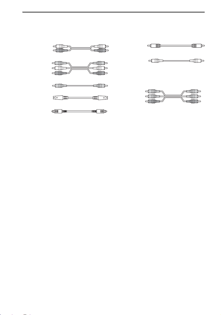
Required cords
The hookup diagrams on the subsequent pages assume the use of the following optional connection
cords (A to H) (not supplied).
A Audio cord
White (L)
Red (R)
B Audio/video cord
Yellow (video)
White (L/audio)
Red (R/audio)
C Video cord
Yellow
D S-video cord
E Optical digital cord
Notes
• Turn off the power to all components before making any connections.
• Be sure to make connections firmly to avoid hum and noise.
• When connecting an audio/video cord, be sure to match the color-coded pins to the appropriate jacks on the
components: yellow (video) to yellow; white (left, audio) to white; and red (right, audio) to red.
• When connecting optical digital cords, insert the cord plugs straight in until they click into place.
• Do not bend or tie optical digital cords.
F Coaxial digital cord
G Monaural audio cord
Black
Tip
Audio cord A can be torn into two monaural audio
cords G.
H Component video cord
Green
Blue
Red
US
6
.
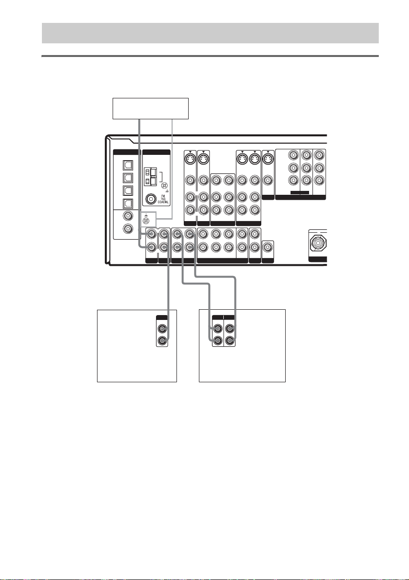
1a: Connecting components with digital audio output jacks
Hooking up a DVD player, TV monitor or satellite tuner
For details on the required cords (A–H), see page 6.
1 Connect the audio jacks.
DVD player
OUTPUT
AUDIO
OUT
L
R
SA-CD/CD
L
R
AF
Y
P
S-VIDEO
S-VIDEO
IN
TV/SAT
L
R
OUT ININ IN
MD/TAPE
VIDEO IN
AUDIO IN
L
R
IN
VIDEO IN
AUDIO IN
DVD VIDEO 2
LRL
FRONT SURROUND
AM
VIDEO OUT
VIDEO IN
L
R
AUDIO OUT
AUDIO IN
R
SURR
BACK
MULTI CH IN
S-VIDEO
OUT
VIDEO OUT
L
R
AUDIO OUT
VIDEO 1
CENTER
SUB
WOOFER
2ND ZONE
S-VIDEO
IN
AUDIO IN
OUT
S-VIDEO
VIDEO OUTVIDEO IN
MONITOR
L
R
WOOFER
PRE OUT
OUT
SUB
B/CB
/B–Y
R/CR
P
/R–Y
TV/SATINDVD
ASSIGNABLE
COMPONENT VIDEO
MONITOR
IN
OUT
+
CEN
DIGITAL
OPTICAL
TV/SAT
IN
MD/
TAPE
IN
MD/
TAPE
OUT
SA-CD/
CD
IN
DVD
IN
SA-CD/
CD
IN
COAXIAL
ASSIGNABLE
(INPUT ONLY)
OUTPUT
DIGITAL
COAXIAL
ANTENNA
SIGNAL GND
PHONO
Getting Started
E
OUTPUT
DIGITAL
OPTICAL
A
L
R
OUTPUT
AUDIO
OUT
Satellite tuner
Note
You can also listen to the sound of your TV by connecting your TV’s audio output jacks to the TV/SAT AUDIO IN
jacks on the receiver. In this case, do not connect the TV’s video output jack to the TV/SAT VIDEO IN jack on the
receiver.
continued
US
7
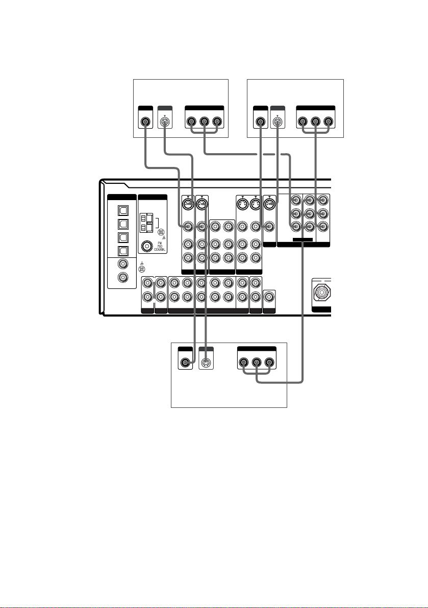
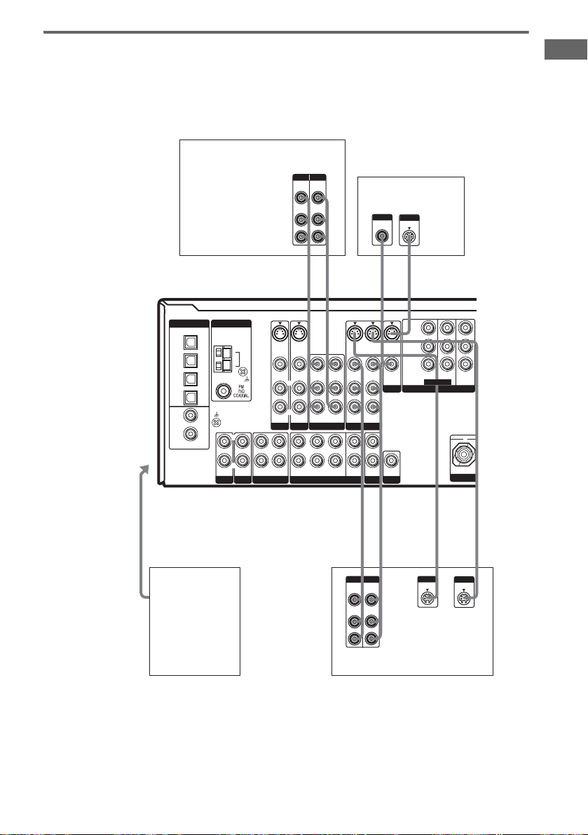
2 Connect the video jacks.
The following illustration shows how to connect a TV or satellite tuner and a DVD player with
COMPONENT VIDEO (Y,
P
/CB/B-Y, PR/CR/R-Y) output jacks. Connecting a TV with component
B
video input jacks allows you to enjoy higher quality video.
DIGITAL
OPTICAL
TV/SAT
IN
MD/
TAPE
IN
MD/
TAPE
OUT
SA-CD/
CD
IN
DVD
IN
SA-CD/
CD
IN
COAXIAL
ASSIGNABLE
(INPUT ONLY)
OUTPUT
VIDEO
ANTENNA
SIGNAL GND
PHONO
L
R
Satellite tuner
OUTPUT
S VIDEO
S-VIDEO
AM
VIDEO IN
AUDIO IN
TV/SAT
L
R
OUT ININ IN
SA-CD/CD
MD/TAPE
CHD
OUTPUT
VIDEO
OUTPUT
COMPONENT
PR/CR/R–Y PB/CB/B–Y
S-VIDEO
IN
IN
VIDEO IN
L
R
AUDIO IN
DVD
FRONT
OUTPUT
S VIDEO
Y
VIDEO OUT
L
R
AUDIO OUT
VIDEO 2
LRL
R
SURROUND
MULTI CH IN
VIDEO IN
AUDIO IN
SURR
BACK
CHHCD D
S-VIDEO
S-VIDEO
OUT
VIDEO OUT
L
R
AUDIO OUT
AUDIO IN
VIDEO 1
CENTER
SUB
OUT
WOOFER
2ND ZONE
OUTPUT
COMPONENT
PR/CR/R–Y PB/CB/B–Y
IN
INPUT
VIDEO
S-VIDEO
VIDEO OUTVIDEO IN
MONITOR
L
R
WOOFER
PRE OUT
OUT
SUB
Y
TV monitor
INPUT
S VIDEO
Y
P
B/CB
/B–Y
R/CR
P
/R–Y
TV/SATINDVD
COMPONENT VIDEO
COMPONENT
PR/CR/R–Y PB/CB/B–Y
ASSIGNABLE
IN
INPUT
MONITOR
OUT
+
CEN
Y
DVD player
Tips
• When using the S-video jacks instead of the video jacks, your monitor must also be connected via an S-video jack.
S-video signals are on a separate bus from the video signals and will not be output through the video jacks.
• On this receiver, standard video signals can be converted to component video or S-video signals and S-video
signals can be converted to component video signals. These upconverted video signals can only be output from the
MONITOR VIDEO OUT jack. However, you cannot convert the component video signals to standard video or
S-video signals.
• When standard video signals (composite video signals) or S-video signals from a VCR etc. are converted upward
on this receiver and then output to your TV, depending on the status of the video signal output, the image on the
TV screen may appear distorted horizontally or no image may be output.
US
8
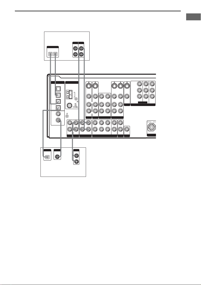
Hooking up an MD/Tape deck or a Super Audio CD/CD player
For details on the required cords (A–H), see page 6.
MD/Tape deck
INPUT OUTPUT
LINE
IN
ANTENNA
SIGNAL GND
PHONO
F*A
L
R
SA-CD/CD
OUTPUT
LINE
L
R
l
INOUT
l
Y
P
S-VIDEO
S-VIDEO
IN
TV/SAT
L
R
OUT ININ IN
MD/TAPE
VIDEO IN
AUDIO IN
L
R
IN
VIDEO IN
AUDIO IN
DVD VIDEO 2
LRL
FRONT SURROUND
AM
LINE
L
R
VIDEO OUT
VIDEO IN
L
R
AUDIO OUT
AUDIO IN
R
SURR
BACK
MULTI CH IN
S-VIDEO
OUT
VIDEO OUT
R
AUDIO OUT
VIDEO 1
CENTER
SUB
WOOFER
L
2ND ZONE
S-VIDEO
IN
AUDIO IN
OUT
VIDEO OUTVIDEO IN
MONITOR
L
R
WOOFER
PRE OUT
S-VIDEO
OUT
SUB
B/CB
/B–Y
R/CR
P
/R–Y
TV/SATINDVD
ASSIGNABLE
COMPONENT VIDEO
MONITOR
IN
OUT
+
CEN
DIGITAL
OPTICAL
OUT
IN
E
EAA
l
OUT
l
DIGITAL
OPTICAL
TV/SAT
IN
MD/
TAPE
IN
MD/
TAPE
OUT
SA-CD/
CD
IN
DVD
IN
SA-CD/
CD
IN
COAXIAL
ASSIGNABLE
(INPUT ONLY)
*
E
DIGITAL
OUTPUT
DIGITAL
OPTICAL
COAXIAL
OUT
Super Audio CD/CD
player
Getting Started
* Connect to either the SA-CD/CD COAXIAL IN or the SA-CD/CD OPTICAL IN jack. We recommend making
connections to the SA-CD/CD COAXIAL IN jack.
If you want to connect several digital components, but cannot find an
unused input
See “Reassigning the digital audio input” (page 35).
Tip
All the digital audio jacks are compatible with 32 kHz, 44.1 kHz, 48 kHz and 96 kHz sampling frequencies.
Notes
• It is not possible to record analog signals if you make only digital connections. Likewise, you cannot record digital
signals if you make only analog connections. To record analog signals, make analog connections. To record digital
signals, make digital connections.
• No sound is output when you play a Super Audio CD disc on the Super Audio CD player connected to the
SA-CD/CD OPTICAL IN or SA-CD/CD COAXIAL IN jack on this receiver. Connect the player to the analog
input jacks (SA-CD/CD IN jacks). Refer to the operating instructions supplied with the Super Audio CD player.
US
9
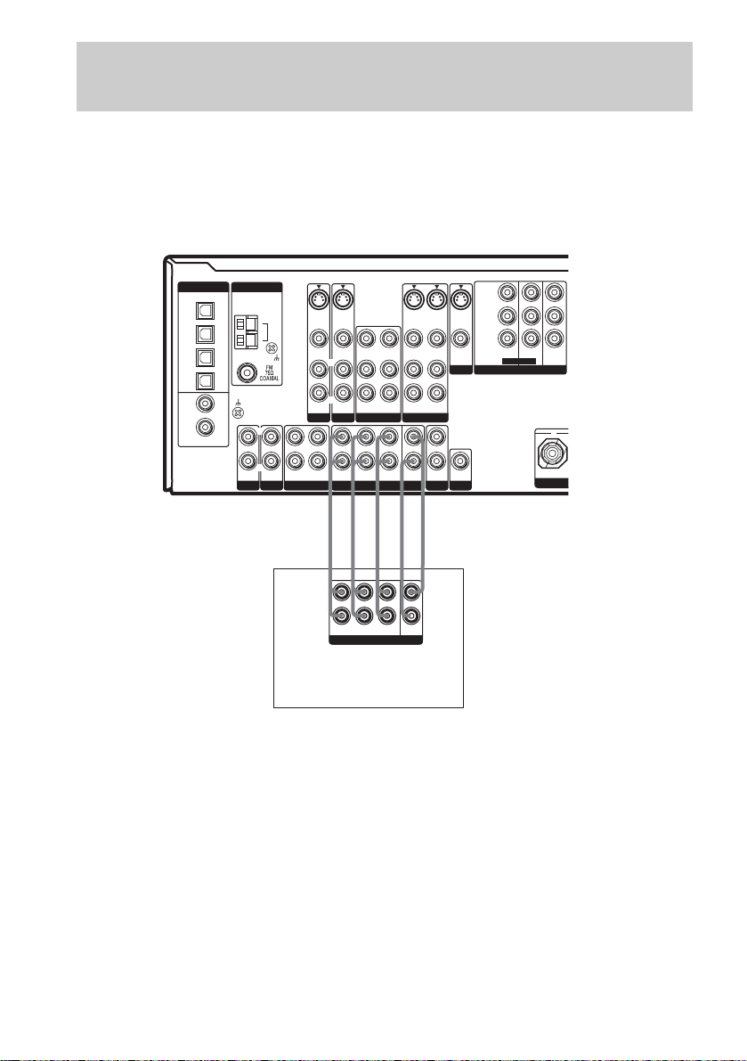
1b: Connecting components with multi channel output
jacks
1 Connect the audio jacks.
If your DVD or Super Audio CD player is equipped with multi channel output jacks, you can connect
it to this receiver’s MULTI CH IN jacks to enjoy the multi channel sound. Alternatively, the multi
channel input jacks can be used to connect an external multi channel decoder.
For details on the required cords (A
DIGITAL
ASSIGNABLE
(INPUT ONLY)
ANTENNA
SIGNAL GND
PHONO
OPTICAL
TV/SAT
IN
MD/
TAPE
IN
MD/
TAPE
OUT
SA-CD/
CD
IN
DVD
IN
SA-CD/
CD
IN
COAXIAL
–H), see page 6.
AM
L
L
R
R
OUT ININ IN
SA-CD/CD
MD/TAPE
S-VIDEO
S-VIDEO
IN
IN
VIDEO IN
VIDEO IN
VIDEO OUT
VIDEO IN
L
L
R
R
AUDIO IN
AUDIO OUT
DVD VIDEO 2
LL
R
R
FRONT
SURROUND
MULTI CH IN
AUDIO IN
AUDIO IN
TV/SAT
AAA GG
SURR
BACK
S-VIDEO
OUT
VIDEO OUT
L
R
AUDIO OUT
VIDEO 1
CENTER
SUB
WOOFER
S-VIDEO
IN
AUDIO IN
L
R
OUT
2ND ZONE
S-VIDEO
OUT
VIDEO OUTVIDEO IN
MONITOR
SUB
WOOFER
PRE OUT
Y
P
B/CB
/B–Y
R/CR
P
/R–Y
TV/SATINDVD
ASSIGNABLE
COMPONENT VIDEO
MONITOR
IN
OUT
+
CEN
L
R
FRONT
SURR
SURROUND
BACK
MULTI CH OUT
CENTER
SUB
WOOFER
DVD player,
Super Audio CD player,
Multi channel decoder, etc.
Tip
This connection also allows you to enjoy software with multi channel audio recorded in formats other than the Dolby
Digital and DTS.
Note
When you make connections to the MULTI CH IN jacks, you will need to adjust the level of the speakers and sub
woofer using the controls on the connected component.
US
10
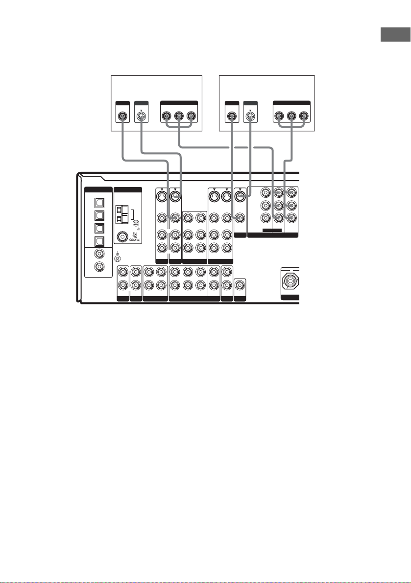
2 Connect the video jacks.
The following illustration shows how to connect a DVD player with COMPONENT VIDEO (Y,
P
/B-Y, PR/CR/R-Y) output jacks. Connecting a TV with component video input jacks allows you
B/CB
to enjoy higher quality video.
TV monitorDVD player
Getting Started
PR/CR/R–Y PB/CB/B–Y
TV/SATINDVD
ASSIGNABLE
IN
INPUT
COMPONENT
MONITOR
OUT
+
Y
HC
CEN
DIGITAL
OPTICAL
TV/SAT
IN
MD/
TAPE
IN
MD/
TAPE
OUT
SA-CD/
CD
IN
DVD
IN
SA-CD/
CD
IN
COAXIAL
ASSIGNABLE
(INPUT ONLY)
OUTPUT
VIDEO
ANTENNA
SIGNAL GND
PHONO
L
R
SA-CD/CD
OUTPUT
S VIDEO
AM
TV/SAT
L
R
OUT ININ IN
MD/TAPE
OUTPUT
COMPONENT
PR/CR/R–Y PB/CB/B–Y
Y
HCD D
S-VIDEO
S-VIDEO
IN
IN
VIDEO IN
VIDEO IN
VIDEO OUT
VIDEO IN
L
L
R
R
AUDIO IN
AUDIO OUT
DVD VIDEO 2
LRL
R
FRONT SURROUND
MULTI CH IN
AUDIO IN
SURR
BACK
AUDIO IN
S-VIDEO
OUT
VIDEO OUT
L
R
AUDIO OUT
VIDEO 1
CENTER
SUB
WOOFER
INPUT
VIDEO
S-VIDEO
IN
AUDIO IN
L
R
OUT
2ND ZONE
PRE OUT
S-VIDEO
OUT
VIDEO OUTVIDEO IN
MONITOR
SUB
WOOFER
INPUT
S VIDEO
Y
B/CB
P
/B–Y
P
R/CR
/R–Y
COMPONENT VIDEO
Tips
• When using the S-video jacks instead of the video jacks, your monitor must also be connected via an S-video jack.
S-video signals are on a separate bus from the video signals and will not be output through the video jacks.
• On this receiver, standard video signals can be converted to component video or S-video signals and S-video
signals can be converted to component video signals. These upconverted video signals can only be output from the
MONITOR VIDEO OUT jack. However, you cannot convert the component video signals to standard video or
S-video signals.
• When standard video signals (composite video signals) or S-video signals from a VCR etc. are converted upward
on this receiver and then output to your TV, depending on the status of the video signal output, the image on the
TV screen may appear distorted horizontally or no image may be output.
11
US
1c: Connecting components with only analog audio jacks
Hooking up audio components
For details on the required cords (A–H), see page 6.
Turntable
A
DIGITAL
OPTICAL
TV/SAT
IN
MD/
TAPE
IN
MD/
TAPE
OUT
SA-CD/
CD
IN
DVD
IN
SA-CD/
CD
IN
COAXIAL
ASSIGNABLE
(INPUT ONLY)
ANTENNA
SIGNAL GND
PHONO
AM
R
OUT ININ IN
SA-CD/CDRMD/TAPE
VIDEO IN
AUDIO IN
TV/SAT
LL
S-VIDEO
IN
S-VIDEO
IN
VIDEO IN
VIDEO OUT
L
R
AUDIO IN
AUDIO OUT
DVD VIDEO 2
LRL
FRONT SURROUND
MULTI CH IN
L
R
R
VIDEO IN
AUDIO IN
SURR
BACK
S-VIDEO
OUT
VIDEO OUT
R
AUDIO OUT
VIDEO 1
CENTER
SUB
WOOFER
L
AUDIO IN
2ND ZONE
S-VIDEO
IN
OUT
S-VIDEO
VIDEO OUTVIDEO IN
MONITOR
L
R
SUB
WOOFER
PRE OUT
OUT
Y
P
B/CB
/B–Y
R/CR
P
/R–Y
TV/SATINDVD
ASSIGNABLE
COMPONENT VIDEO
MONITOR
IN
OUT
+
CEN
l
OUT
A
INPUT OUTPUT
LINE
L
R
LINE
MD/Tape deck
Super Audio CD/
CD player
A
OUTPUT
LINE
Note
If your turntable has a ground wire, connect it to the U SIGNAL GND terminal.
US
12
L
R
l
A
IN
Hooking up video components
If you connect your TV to the MONITOR jacks, you can watch the video from the selected input
(page 23). You can also display the SPEAKER SET UP, LEVEL, EQUALIZER and CUSTOMIZE
menu settings and sound fields on your TV by pressing ON SCREEN. For details on the required cords
(A
–H), see page 6.
VCR
OUTPUTINPUT
VIDEO
VIDEO
IN
To the VIDEO 3
IN/PORTABLE
AV IN jacks
(Front panel)
DIGITAL
OPTICAL
TV/SAT
IN
MD/
TAPE
IN
MD/
TAPE
OUT
SA-CD/
CD
IN
DVD
IN
SA-CD/
CD
IN
COAXIAL
ASSIGNABLE
(INPUT ONLY)
ANTENNA
SIGNAL GND
PHONO
L
R
SA-CD/CD
OUT
AUDIO
AUDIO
OUT
IN
L
R
BB DC
L
OUT
S-VIDEO
S-VIDEO
IN
TV/SAT
L
R
OUT ININ IN
MD/TAPE
VIDEO IN
AUDIO IN
R
IN
VIDEO IN
L
AUDIO IN
DVD VIDEO 2
FRONT SURROUND
AM
VIDEO OUT
L
R
AUDIO OUT
LRL
R
MULTI CH IN
L
VIDEO IN
AUDIO IN
SURR
BACK
IN
S-VIDEO
OUT
VIDEO OUT
AUDIO OUT
VIDEO 1
CENTER
SUB
WOOFER
INPUT
VIDEO
S-VIDEO
IN
VIDEO IN
L
R
AUDIO IN
OUT
2ND ZONE
TV monitor
INPUT
S VIDEO
S-VIDEO
OUT
VIDEO OUT
MONITOR
L
R
SUB
WOOFER
PRE OUT
Y
B/CB
P
/B–Y
PR/C
R
/R–Y
TV/SATINDVD
ASSIGNABLE
COMPONENT VIDEO
MONITOR
IN
OUT
+
CEN
Getting Started
B, D
Camcorder or
video game
OUT
B
VIDEO
AUDIO
L
OUTPUTINPUT
VIDEO
IN
OUT
AUDIO
OUT
IN
L
IN
BDD
INPUT
S VIDEO
L
R
VCR
L
OUTLIN
OUTPUT
S VIDEO
13
US
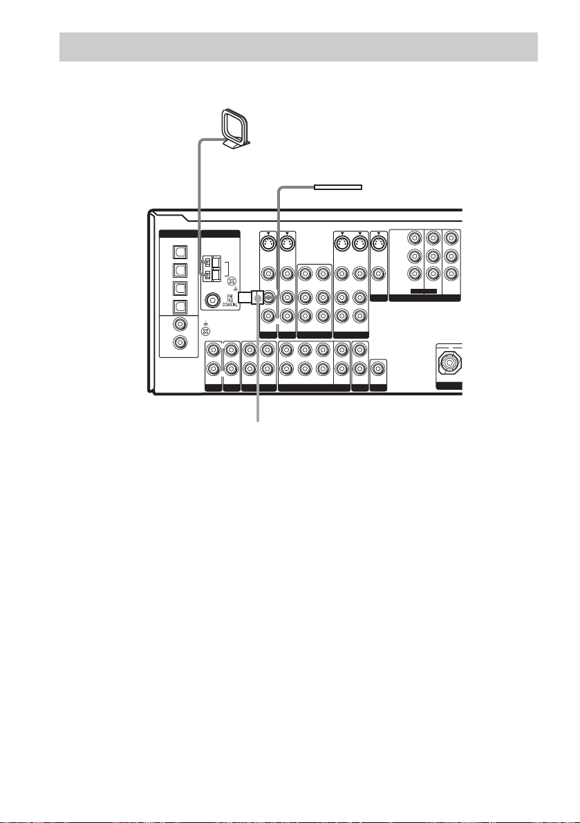
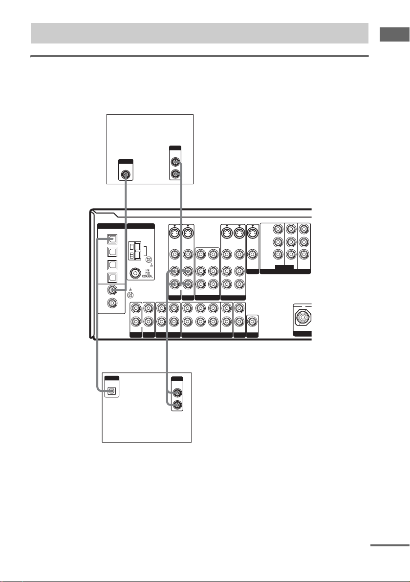
2: Connecting the antennas
Connect the supplied AM loop antenna and FM wire antenna.
AM loop antenna
(supplied)
DIGITAL
IN
IN
IN
IN
IN
ASSIGNABLE
(INPUT ONLY)
ANTENNA
SIGNAL GND
PHONO
L
R
SA-CD/CD
S-VIDEO
S-VIDEO
IN
IN
AM
VIDEO IN
VIDEO IN
L
R
AUDIO IN
AUDIO IN
TV/SAT
DVD VIDEO 2
L
R
FRONT SURROUND
OUT ININ IN
MD/TAPE
VIDEO OUT
L
R
AUDIO OUT
LRL
R
MULTI CH IN
VIDEO IN
AUDIO IN
SURR
BACK
S-VIDEO
VIDEO OUT
AUDIO OUT
CENTER
WOOFER
*
OPTICAL
TV/SAT
MD/
TAPE
MD/
TAPE
OUT
SA-CD/
CD
DVD
SA-CD/
CD
COAXIAL
OUT
R
VIDEO 1
SUB
S-VIDEO
IN
L
AUDIO IN
L
R
OUT
2ND ZONE
FM wire antenna
(supplied)
Y
B/CB
P
S-VIDEO
OUT
/B–Y
P
R/CR
/R–Y
TV/SATINDVD
VIDEO OUTVIDEO IN
MONITOR
PRE OUT
SUB
WOOFER
ASSIGNABLE
COMPONENT VIDEO
MONITOR
IN
OUT
+
CEN
* The shape of the connector varies depending on the area code.
Notes
• To prevent noise pickup, keep the AM loop antenna away from the receiver and other components.
• Be sure to fully extend the FM wire antenna.
• After connecting the FM wire antenna, keep it as horizontal as possible.
• Do not use the U SIGNAL GND terminal for grounding the receiver.
US
14
3: Connecting speakers
Connect your speakers to the receiver. This receiver allows you to use a 7.1 channel speaker system.
To fully enjoy theater-like multi channel surround sound requires five speakers (two front speakers, a
center speaker, and two surround speakers) and a sub woofer (5.1 channel).
You can enjoy high fidelity reproduction of DVD software recorded in the Surround EX format if you
connect one additional surround back speaker (6.1 channel) or two surround back speakers (7.1
channel) (see “Selecting the surround back decoding mode” on page 33).
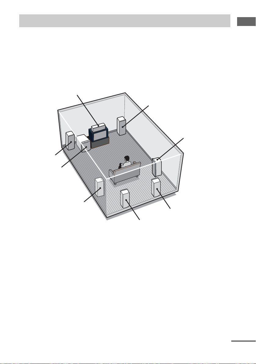
Example of 7.1 channel speaker system configuration
Center speaker
Front speaker (right)
Surround speaker (right)
Front speaker (left)
Sub woofer
Getting Started
Surround speaker (left)
Surround back speaker (right)
Surround back speaker (left)
Tips
• When you connect 6.1 channel speaker system, place the surround back speaker behind the listening position (see
“When placing only one surround back speaker” illustration on page 20).
• Since the sub woofer does not emit highly directional signals, you can place it wherever you want.
continued
15
US
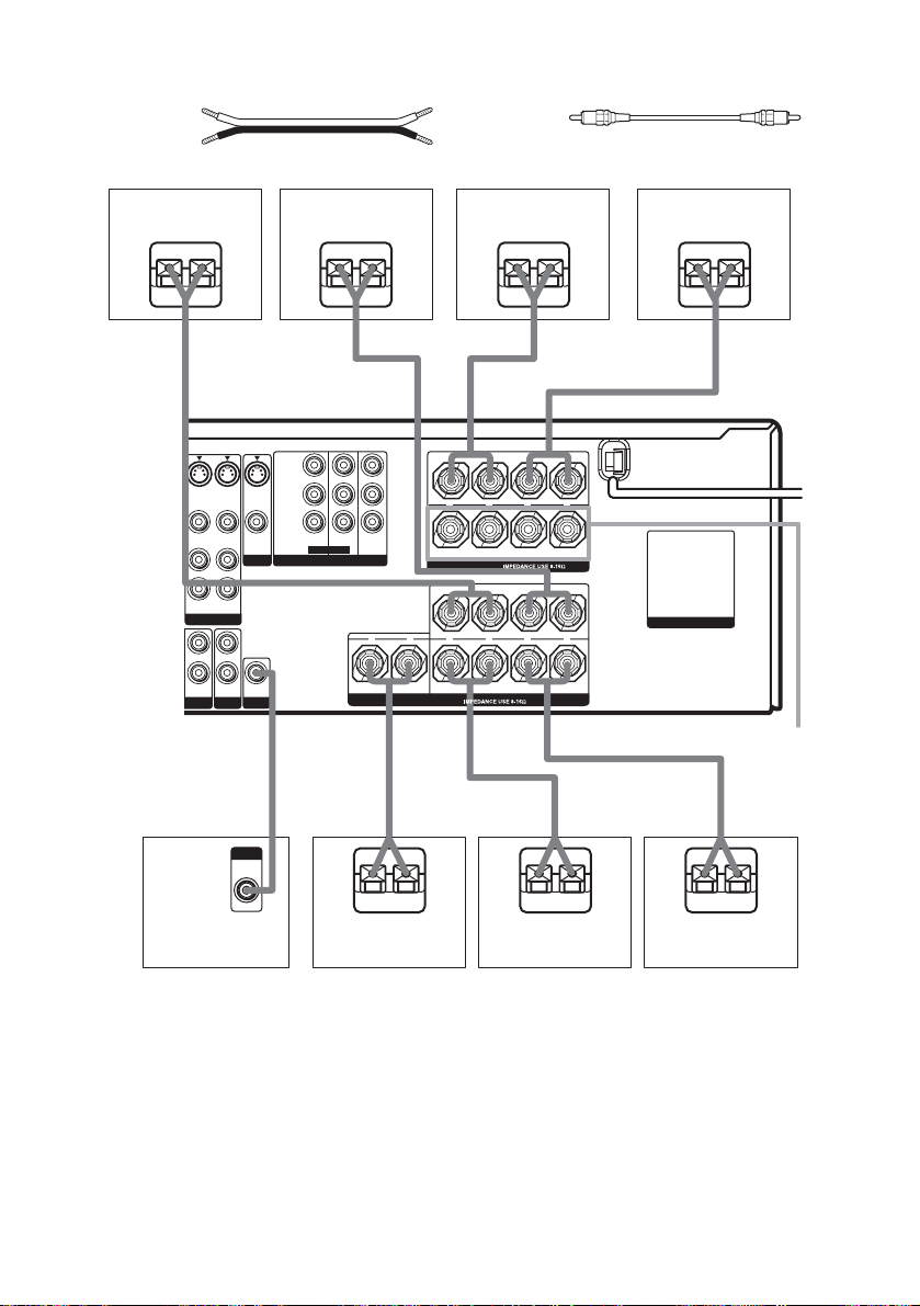
Required cords
A Speaker cords (not supplied)
(+)
(–)
B Monaural audio cord (not supplied)
Black
Surround speaker
(right)
Ee
S-VIDEO
S-VIDEO
OUT
IN
VIDEO OUT
L
R
AUDIO IN
AUDIO OUT
VIDEO 1
CENTER
SUB
OUT
WOOFER
2ND ZONE
S-VIDEO
VIDEO OUTVIDEO IN
MONITOR
L
R
WOOFER
PRE OUT
B
INPUT
AUDIO
IN
OUT
SUB
Surrond speaker
(left)
Ee
A
Y
P
B/CB
/B–Y
R/CR
P
/R–Y
TV/SATINDVD
MONITOR
IN
ASSIGNABLE
COMPONENT VIDEO
E
Front speaker
(right)
Ee
A
FRONT A
LR
FRONT B
SURROUND
––
LR
LR
––
LR
++
OUT
SPEAKERS
+
+ +
–
SURROUND BACK (2ND ZONE)CENTER
SPEAKERS
Front speaker
(left)
Ee
AA
AC OUTLET
SPEAKERS
FRONT B*
A
e
E
A
E
e
A
e
Sub woofer
Center speaker
Surround back
speaker (right)**
Surround back
speaker (left)**
* If you have an additional front speaker system, connect them to the SPEAKERS FRONT B terminals. You can
select the front speakers you want to use with SPEAKERS (OFF/A/B/A+B) button. For details, see “Selecting the
speaker system” (page 42).
** If you connect only one surround back speaker, connect it to the SPEAKERS SURROUND BACK L terminals.
US
16
4: Connecting the AC
N
N
O
power cord
Performing initial setup
operations
Before using the receiver for the first time,
Getting Started
initialize the receiver by performing the
Connecting the AC power
cord
Connect the AC power cord to a wall outlet.
AC power cord
following procedure.
This procedure can also be used to return
settings you have made to their factory defaults.
Use the buttons on the receiver for the operation.
1 Press ?/1 to turn off the receiver.
2 Hold down ?/1 for 5 seconds.
“PUSH ENTER” flashes in the display.
T A
L
+
–
L
T B
UND
L
+
–
L
CK (2ND ZONE)
AC OUTLET
* The configuration, shape, and number of AC outlets
vary according to the area code.
Notes
• The AC OUTLET(s) on the rear of the receiver is a
switched outlet, which supplies power to the
connected component only while the receiver is
turned on.
• Make sure that the total power consumption of the
component(s) connected to the receiver’s AC
OUTLET(s) does not exceed the wattage stated on
the rear panel. Do not connect high-wattage
electrical home appliances such as electric irons,
fans, or TVs to this outlet. This may cause a
malfunction.
SWITCHED 120W/1A MAX
AC 120V 60Hz
AC OUTLET
*
b
To a wall
outlet
3 Press ENTER.
“MEMORY CLEARING” appears in the
display for a while, then “MEMORY
CLEARED” appears.
The following are reset to their factory
settings.
• All settings in the SPEAKER SET UP,
LEVEL, EQUALIZER and
CUSTOMIZE menus.
• The sound field memorized for each
input and preset station.
• All sound field parameters.
• All preset stations.
• All index names for inputs and preset
stations.
• MASTER VOLUME –/+ is set to
“VOLUME MIN”.
• Input is set to DVD.
US
17

5: Setting up the speakers
You can use the SPEAKER SET UP menu to set
the size, distance and location of the speakers
connected to this receiver.
1 Press ?/1 to turn on the receiver.
2 Press MAIN MENU repeatedly to select
“SET UP”.
3 Turn MENU to select the parameter you
want to adjust.
For details, see “SPEAKER SET UP menu
parameters” below.
Note
Some speaker setup items may appear dimmed in
the display. This means that they have been
adjusted automatically due to other speaker
settings or may not be adjustable.
4 Turn –/+ to select the setting you want.
The setting is entered automatically.
5 Repeat steps 3 and 4 until you have set
all of the items that follow.
SPEAKER SET UP menu
parameters
The initial settings are underlined.
x EASY SETUP XXX (Speaker easy setup)
•YES
If you want to set up your speakers
automatically, select “YES”. You can select a
pre-defined speaker pattern (see the supplied
“Easy Setup Guide”).
•NO
If you want to adjust the settings of each
speaker manually, select “NO”.
x SP PATTERN X–X
(Speaker setup pattern)
When “EASY SETUP” is set to “YES”, select
the speaker setup pattern. Turn –/+ to select the
speaker setup pattern and press ENTER to enter
the selection. Check your speaker setup pattern
using the supplied “Easy Setup Guide”.
x SUB WOOFER XXX
(Sub woofer selection)
•YES
If you connect a sub woofer, select “YES”.
•NO
If you did not connect a sub woofer, select
“NO”. The front speakers are automatically
set to “LARGE” and you cannot change this
setting. This activates the bass redirection
circuitry and outputs the LFE signals from
other speakers.
• In order to take full advantage of the Dolby
Digital bass redirection circuitry, we
recommend that you set the cut off frequency
on the sub woofer as high as possible.
x FRONT SP XXXXX
(Front speakers size)
• LARGE
If you connect large speakers that will
effectively reproduce bass frequencies, select
“LARGE”. Normally, select “LARGE”.
•SMALL
If the sound is distorted, or you feel a lack of
surround effects when using multi channel
surround sound, select “SMALL” to activate
the bass redirection circuitry and output the
front channel bass frequencies from the sub
woofer. When the front speakers are set to
“SMALL”, the center, surround and surround
back speakers are also automatically set to
“SMALL” (unless previously set to “NO” or
to “ZONE-2”*).
* For surround back speakers only.
x CTR SP XXXXX
(Center speaker size)
• LARGE
If you connect a large speaker that will
effectively reproduce bass frequencies, select
“LARGE”. Normally, select “LARGE”.
However, if the front speakers are set to
“SMALL”, you cannot set the center speaker
to “LARGE”.
•SMALL
If the sound is distorted, or you feel a lack of
surround effects when using multi channel
surround sound, select “SMALL” to activate
the bass redirection circuitry and output the
center channel bass frequencies from the front
speakers (if set to “LARGE”) or sub woofer.
a)
18
US

•NO
If you did not connect a center speaker, select
“NO”. The sound of the center channel will be
output from the front speakers.
x SURR SP XXXXX
(Surround speakers size)
b)
• LARGE
If you connect large speakers that will
effectively reproduce bass frequencies, select
“LARGE”. Normally, select “LARGE”.
However, if the front speakers are set to
“SMALL”, you cannot set the surround
speakers to “LARGE”.
•SMALL
If the sound is distorted, or you feel a lack of
surround effects when using multi channel
surround sound, select “SMALL” to activate
the bass redirection circuitry and output the
surround channel bass frequencies from the
sub woofer or other “LARGE” speakers.
•NO
If you did not connect surround speakers,
select “NO”.
x SB SP XXXXXX
(Surround back speakers selection)
c)
When the surround speakers size parameter is
set to “NO”, the surround back speakers
selection parameter is also automatically set to
“NO” (unless previously set to “ZONE-2”).
• DUAL
If you connect two surround back speakers,
select “DUAL”. The sound will be output to a
maximum of 7.1 channels.
•SINGLE
If you connect only one surround back
speaker, select “SINGLE”. The sound will be
output to a maximum of 6.1 channels.
•NO
If you did not connect surround back
speakers, select “NO”.
• ZONE-2
If you want to assign both your surround back
speakers to another room or zone, select
“ZONE-2”. For details, see “Using the
surround back speakers for 2nd zone” on
page 44.
Tips
• a)–c) correspond to the following Dolby Pro Logic
modes
a) NORMAL
b) PHANTOM
c) 3 STEREO
• The “LARGE” and “SMALL” settings for each
speaker determine whether the internal sound
processor will cut the bass signal from that channel.
When the bass is cut from a channel, the bass
redirection circuitry sends the corresponding bass
frequencies to the sub woofer or other “LARGE”
speakers.
However, since bass sounds have a certain amount of
directionality, it is best not to cut them, if possible.
Therefore, even when using small speakers, you can
set them to “LARGE” if you want to output the bass
frequencies from that speaker. On the other hand, if
you are using a large speaker, but prefer not to have
bass frequencies output from that speaker, set it to
“SMALL”.
If the overall sound level is lower than you prefer, set
all speakers to “LARGE”. I f there is not enough bass,
you can use the BASS parameter in the
EQUALIZER menu to boost the bass levels. To
adjust the bass, see page 38.
Getting Started
continued
19
US
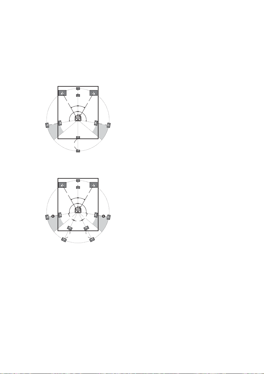
x FRONT DIST. XX ft.
(Front speaker distance)
Initial setting: 10 ft.
Lets you set the distance from your listening position
to the front speakers (A). You can adjust from 3 to 23
feet in 1 foot steps.
If both front speakers are not placed an equal distance
from your listening position, set the distance to the
closest speaker.
When placing only one surround back speaker
B
A
CC
A
30˚30˚
100˚-120˚100˚-120˚
D
When placing two surround back speakers
(The angle E should be the same)
B
AA
30˚30˚
100˚-120˚100˚-120˚
E
E
E
DD
x CTR DIST. XX ft.
(Center speaker distance)
Initial setting: 10 ft.
Lets you set the distance from your listening position
to the center speaker. Center speaker distance should
be set from a distance equal to the front speaker
distance (A) to a distance 5 feet closer to your
listening position (B).
x SURR DIST. XX ft.
(Surround speaker distance)
Initial setting: 10 ft.
Lets you set the distance from your listening position
to the surround speakers. Surround speaker distance
should be set from a distance equal to the front speaker
distance (A) to a distance 15 feet closer to your
listening position (C).
If both surround speakers are not placed an equal
distance from your listening position, set the distance
to the closest speaker.
x SB DIST. XX ft.
(Surround back speaker distance)
Initial setting: 10 ft.
Lets you set the distance from your listening position
to the surround back speaker. Surround back speaker
distance should be set from a distance equal to the front
speaker distance (A) to a distance 15 feet closer to
your listening position (D).
If you connect two surround back speakers and both
surround back speakers are not placed an equal
distance from your listening position, set the distance
to the closest speaker.
Tip
The receiver lets you to input the speaker position in
terms of distance. However, it is not possible to set the
center speaker further than the front speakers. Also, the
center speaker cannot be set more than 5 feet closer
than the front speakers.
Likewise, the surround speakers and the surround back
speakers cannot be set further away from the listening
position than the front speakers. And they can be no
more than 15 feet closer.
This is because incorrect speaker placement is not
conducive to the enjoyment of surround sound.
Please note that, setting the speaker distance closer than
the actual location of the speakers will cause a delay in
the output of the sound from that speaker. In other
words, the speaker will sound like it is further away.
For example, setting the center speaker distance 3–6
feet closer than the actual speaker position will create
a fairly realistic sensation of being “inside” the screen.
If you cannot obtain a satisfactory surround effect
because the surround speakers are too close, setting the
surround speaker distance closer (shorter) than the
actual distance will create a larger sound stage.
Adjusting these parameter while listening to the sound
often results in much better surround sound. Give it a
try!
20
US
 Loading...