

Page 1

FM Stereo
FM-AM Receiver
3-856-142-13(1)
Operating instructions
STR-DE905G
STR-DE805G
© 1996 by Sony Corporation
Page 2
WARNING
- Consult the dealer or an experienced
radio/TV technician for help.
Precautions
To prevent fire or shock
hazard, do not expose
the unit to rain or
moisture.
This symbol is intended to alert the user
to the presence of uninsulated
“dangerous voltage” within the
product’s
enclosure that may be of sufficient
magnitude to constitute a risk of electric
shock to persons.
This symbol is intended to alert the user
to the presence of important operating
and maintenance (servicing)
instructions in the literature
accompanying the appliance.
IMPORTANT
This equipment has been tested and
found to comply with the limits for a
Class B digital device, pursuant to Part
15 of the FCC Rules.
These limits are designed to provide
reasonable protection against harmful
interference in a residential installation.
This equipment generates, uses, and can
radiate radio frequency energy and, if
not installed and used in accordance
with the instructions, may cause
harmful interference to radio
communications. However, there is no
guarantee that interference will not
occur in a particular installation. If this
equipment does cause harmful
interference to radio or television
reception, which can be determined by
turning the equipment off and on, the
user is encouraged to try to correct the
interference by one or more of the
following measures:
- Reorient or relocate the receiving
antenna.
- Increase the separation between the
equipment and receiver.
- Connect the equipment into an outlet
on a circuit different from that to
2
which the receiver is connected.
CAUTION
You are cautioned that any change or
modifications not expressly approved in
this manual could void your authority
to operate this equipment.
Note to CATV system installer
This reminder is provided to call the
CATV system installer’s attention to
Article 820-40 of the NEC that provides
guidelines for proper grounding and, in
particular, specifies that the cable
ground shall be connected to the
grounding system of the building, as
close to the point of cable entry as
practical.
Note on the remote commander:
This device complies with Part 15 of the
FCC Rules. Operation is subject to the
following two conditions: (1) This
device may not cause harmful
interference, and (2) this device must
accept any interference received,
including interference that may cause
undesired operation.
CAUTION
Use of this appliance with some systems
may present a shock or fire hazard. Do
not use with any units which have the
following marking located near output.
WARNING: HAZARDOUS ENERGY !
Owner’s record
The model and serial numbers are
located on the rear of the unit. Record
the serial number in the space provided
below. Refer to them whenever you call
upon your Sony dealer regarding this
product.
Model No. STR-DE905G/STR-DE805G
Serial No.
For the customers in Canada
CAUTION
TO PREVENT ELECTRIC SHOCK, DO
NOT USE THIS POLARIZED AC PLUG
WITH AN EXTENSION CORD,
RECEPTACLE OR OTHER OUTLET
UNLESS THE BLADES CAN BE FULLY
INSERTED TO PREVENT BLADE
EXPOSURE.
This class B digital apparatus meets all
requirements of the Canadian
Interference-Causing Equipment
Regulations.
On safety
• Should any solid object or liquid fall
into the cabinet, unplug the receiver
and have it checked by qualified
personnel before operating it any
further.
On power sources
• Before operating the receiver, check
that the operating voltage is identical
with your local power supply. The
operating voltage is indicated on the
nameplate at the rear of the receiver.
• This unit is not disconnected from the
AC power source as long as it is
connected to the wall outlet, even if
the unit itself has been turned off.
• If you are not going to use the
receiver for a long time, be sure to
disconnect the receiver from the wall
outlet. To disconnect the AC power
cord, grasp the plug itself; never pull
the cord.
• One blade of the plug is wider than
the other for the purpose of safety
and will fit into the wall outlet only
one way. If you are unable to insert
the plug fully into the outlet, contact
your dealer.
• AC power cord must be changed
only at the qualified service shop.
On placement
• Do not install the appliance in a
confined space, such as a bookcase or
built-in cabinet.
• Place the receiver in a location with
adequate ventilation to prevent heat
buildup and prolong the life of the
receiver.
• Do not place the receiver near heat
sources, or in a place subject to direct
sunlight, excessive dust or
mechanical shock.
• Do not place anything on top of the
cabinet that might block the
ventilation holes and cause
malfunctions.
On operation
• Before connecting other components,
be sure to turn off and unplug the
receiver.
On cleaning
• Clean the cabinet, panel and controls
with a soft cloth slightly moistened
with a mild detergent solution. Do
not use any type of abrasive pad,
scouring powder or solvent such as
alcohol or benzine.
Page 3
For the customers in the USA
For detailed safety precautions, see the
“IMPORTANT SAFEGUARDS” leaflet.
If you have any question or problem
concerning your receiver, please
consult your nearest Sony dealer.
About This Manual
The instructions in this manual are for
models STR-DE905G and STR-DE805G.
Check your model number by looking
at the lower right corner of the front
panel. In this manual, the STR-DE905G
is the model used for illustration
purposes, any difference in operation is
clearly indicated in the text, for
example, “STR-DE905G only”.
Conventions
• The instructions in this manual
describe the controls in the on-screen
display. You can also use the controls
on the receiver if they have the same
or similar names as those in the onscreen display.
• The following icons are used in this
manual:
Indicates hints and tips for
making the task easier.
This receiver incorporates the Dolby Pro
Logic Surround system.
Manufactured under license from Dolby
Laboratories Licensing Corporation.
“Dolby ,” the double-D symbol a and
“Pro Logic” are trademarks of Dolby
Laboratories Licensing Corporation.
T
ABLE OF CONTENTS
Introduction
Features 4
Understanding How the Receiver Works: STR-DE905G 6
: STR-DE805G 7
Getting Started
Unpacking 8
Hookup Overview 8
RC Antenna Hookups (STR-DE905G only) 9
IR Repeater Hookups 9
Antenna Hookups 10
Audio Component Hookups 10
Speaker System Hookups 11
TV/VCR Hookups 12
AC Hookups 13
Before You Use Your Receiver 13
Preparing and Using the Remote
Inserting Batteries into the Remote : STR-DE905G 14
: STR-DE805G 14
Preventing Interference Between Multiple Remotes
(STR-DE905G only) 15
How to Use the Remote :STR-DE905G 15
: STR-DE805G 16
Registering a TV or Monitor 17
Registering Audio/Video Equipment 19
Programming Infrared (IR) codes from other remotes
(USER IR setting) 22
Basic Operations
Selecting a Component 24
Tuning and Presetting Radio Stations 26
Recording 27
Using the Sleep Timer 29
Using Sound Fields
Introduction 30
Using Pre-programmed Sound Fields 30
Getting the Most Out of Dolby Pro Logic Surround Sound 32
Customizing Sound Fields 33
Advanced Operations
Using the Index functions 35
Operating a CD Changer 37
Enjoying Two Components at the Same Time 38
Operating Several Components in Sequence Automatically
(macro play) 39
Settings and Adjustments
Remote Operation of Audio Sources Without the TV
(illuminated control flasher) 40
Playing Sources Automatically (auto play) 41
Starting a Source Automatically at Power On (auto start) 41
Adjusting the Sensitivity of the Remote 42
Selecting the Display Parameters 42
Adjusting the Position of the On-Screen Display 43
Additional Information
Front Panel Descriptions 44
Rear Panel Descriptions 45
Troubleshooting 46
Specifications 48
Glossary 49
Index 50
3
Page 4
Introduction
Features
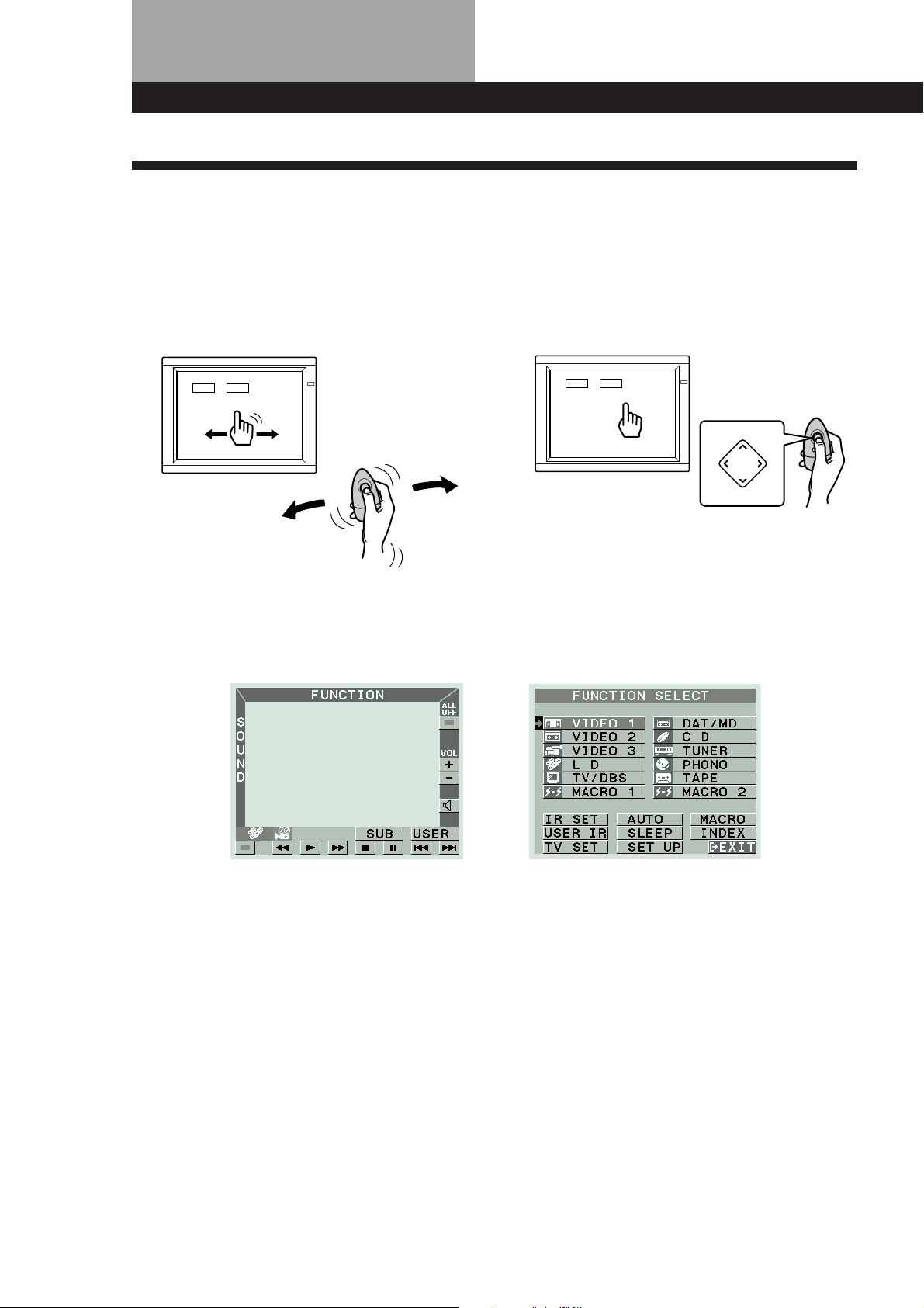
On-screen control of Audio/Video components
The STR-DE905G and STR-DE805G FM Stereo/FM-AM receivers are audio/ video control centers with a unique
interface. By connecting the receivers to your TV, an on-screen display appears and lets you operate the various
connected audio/video components. Use the remote to move the pointer (hand-shaped icon) on the on-screen
display and select functions.
STR-DE905G STR-DE805G
Â
Mm
µ
Â
PUSH
ENTER
Mm
µ
This unit’s on-screen display lets you control audio/video components as well as any other device that can be
controlled by an infrared remote control, such as lighting fixtures.
For details on how the receiver controls other equipment, see pages 6 and 7.
4
Page 5
Introduction
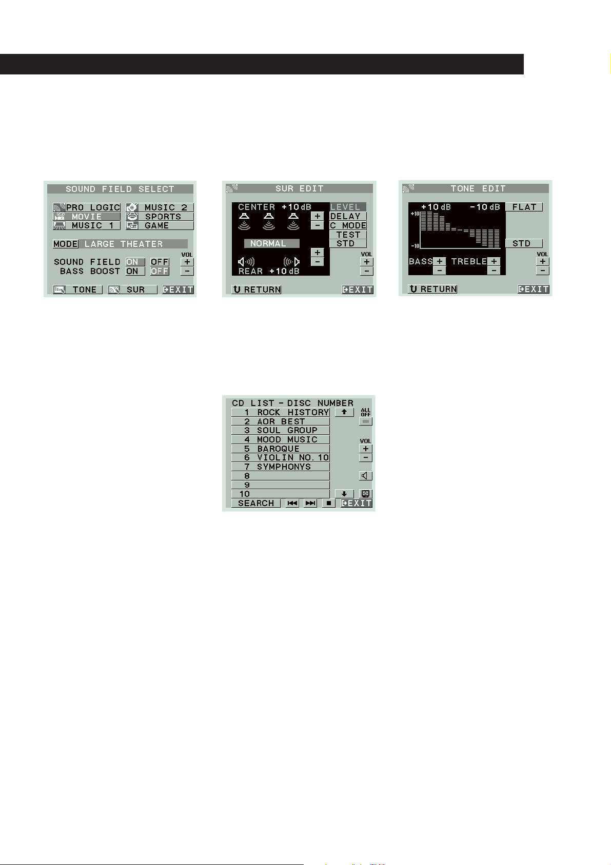
A wide variety of sound fields including Dolby Pro Logic surround
Since the receiver comes preset with 12 different sound fields (like HALL, THEATER, ARENA, etc.), you can enjoy exciting
sound effects simply by choosing one from the SOUND FIELD SELECT screen.
The receiver also incorporates a Dolby Pro Logic decoder, so you can enjoy programs recorded in Dolby Surround with a
surround effect similar to a movie theater.
CD Changer Control
Connecting a Sony CD changer equipped with a Control A1 terminal allows you to access and display the disc information
stored in the CD changer in alphabetical order, numerical order, or by group name. You can also select the disc to be played
discs from the on-screen display using the receiver’s remote.
5
Page 6
Getting StartedIntroduction
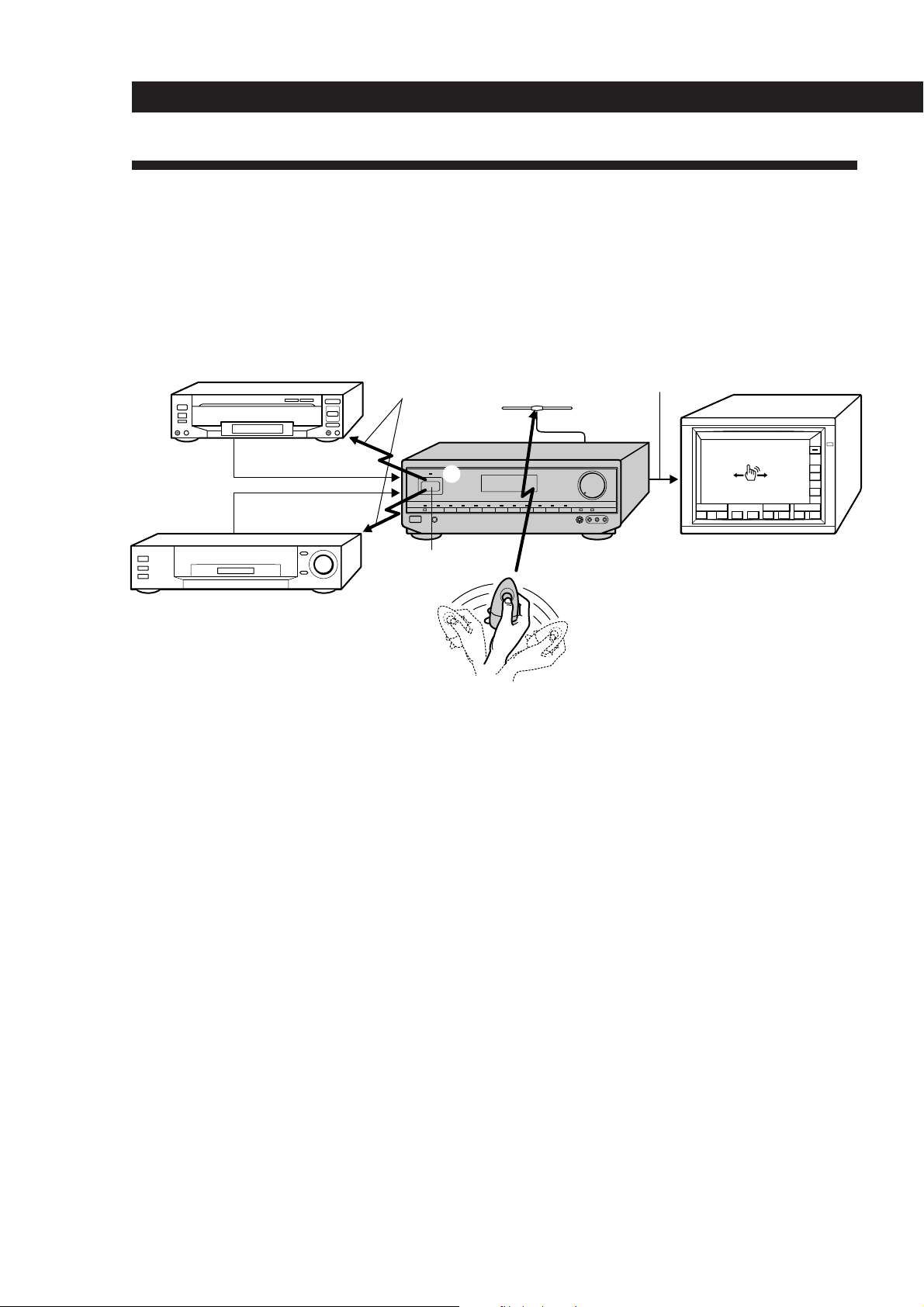
Understanding How the Receiver Works: STR-DE905G
Before you can use the remote to control the receiver, you must connect the remote control (RC) antenna as shown
below.
Steel beams within walls and other metallic objects may interfere with signal reception by the RC antenna. To
prevent this, keep the RC antenna at least 20 inches (about 50 cm) away from all metallic objects.
Since this receiver uses menu operations, you must connect a TV.
Video signal (Input from source
LD player, etc.
IR control codes
RC antenna
components combined with on-screen
display)
Video signal
Video signal
3
IR repeater
STR-DE905G
FUNCTION
S
O
U
N
D
2
()0pP=+
TV (monitor)
ALL
OFF
VOL
+
–
USERSUB
1
VCR, etc.
On-screen operation
The remote commander emits a constant radio frequency (RF) signal that conveys any movement of the remote
1
commander to the receiver via the RC antenna (1 above).
2 This controls the movement of the pointer (hand icon) in the on-screen display (2 above).
3 When you move the pointer to an on-screen icon, and press the button on the remote, the infrared (IR) repeater
transmits the corresponding IR control code to the respective program source (3 above).
If the screen flickers or the pointer does not move
The RF signal from the remote is being obstructed and is not reaching the RC antenna (1 above). Reposition the RC antenna or
bring the remote commander closer to the RC antenna.
If the program source fails to respond or is slow to respond
The IR control code from the IR repeater is not fully reaching the infrared receptor on the program source. Connect the extra IR
repeater (supplied) and position it facing the program source (see “IR Repeater Hookups” on page 9).
If some of the programmed on-screen controls are unresponsive or slow, rerecord the IR codes for those buttons ( see
“Registering non-Sony Audio/Video equipment” on page 19).
6
Page 7
Introduction
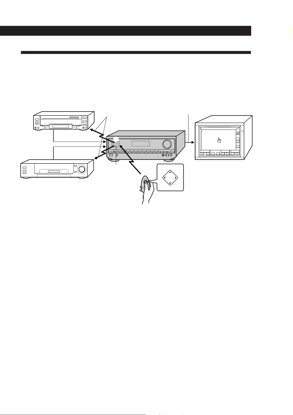
Understanding How the Receiver Works: STR-DE805G
The remote control supplied with the STR-DE805 uses infrared (IR) rays to command the receiver and control the onscreen display.
Since this receiver uses menu operations, you must connect a TV.
Video signal (Input from source
LD player, etc.
IR control codes
components combined with on-screen
display)
Video signal
Video signal
STR-DE805G
3
FUNCTION
S
O
U
N
D
Â
2
Mm
µ
()0pP=+
USERSUB
TV (monitor)
Â
PUSH
ENTER
Mm
VCR, etc.
IR reeator
and receptor
1
µ
On-screen operation
1 The remote commander emits an infrared (IR) signal when you press direction control button (1 above).
2 This controls the movement of the pointer (hand icon) in the on-screen display (2 above).
3 When you move the pointer to an on-screen icon, and press the center of the direction control button, the
infrared (IR) repeater transmits the corresponding IR control code to the respective program source (3 above).
If the screen does not appear or the pointer does not move when you press the direction control button
The IR code from the remote is not fully reaching the infrared receptor on the receiver (1 above). Make sure there are no
obstacles between the remote and the receiver.
ALL
OFF
VOL
+
–
If the program source fails to respond or is slow to respond
The IR control code from the IR repeater is not fully reaching the infrared receptor on the program source. Connect the extra IR
repeater (supplied) and position it facing the program source (see “IR Repeater Hookups” on page 9).
If some of the programmed on-screen controls are unresponsive or slow, rerecord the IR codes for those buttons ( see
“Registering non-Sony Audio/Video equipment” on page 19).
7
Page 8
Getting Started
Unpacking
Check that you received the following items with the
receiver:
• FM wire antenna (1)
• AM loop antenna (1)
• Remote commander RM-VP1 (remote) (STR-DE905G
only) (1)
• Remote commander RM-VR1 (remote) (STR-DE805G
only) (1)
• Size AA (R6) batteries (2)
• Remote control (RC) antenna (1) (STR-DE905G only)
• IR repeater (1)
• Video cable (1)
• Control S cord (1)
• Getting Started and Basic Operation Guide (1)
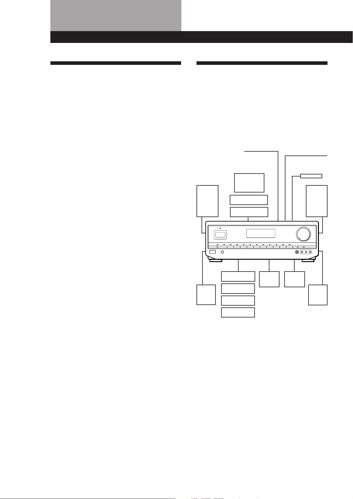
Hookup Overview
The receiver allows you to connect and control the
following audio/video components. Follow the
hookup procedures for the components that you want
to connect to the receiver on the pages specified. To
learn the locations and names of each jack, see “Rear
Panel Descriptions” on page 45.
Speaker
System
Hookups (11)
Front
speaker
(L)
RC Antenna Hookups
(STR-DE905G only) (9)
TV/VCR Hookups (12)
TV
VCR
LD player
Antenna Hookups (10)
AM/FM antenna
IR Repeater
Hookups (9)
Front
speaker
(R)
Center
speaker
Active
woofer
Rear
speaker
(R)
Rear
speaker
(L)
CD player
Tape deck
DAT/MD deck
Turntable
Audio Component
Hookups (10)
Before you get started
• Turn off the power to all components before making
any connections.
• Do not connect the AC power cords until all of the
connections are completed.
• Be sure to make connections firmly to avoid hum
and noise.
• When connecting an audio/video cable, be sure to
match the color-coded pins to the appropriate jacks
on the components: Yellow (video) to Yellow; White
(left, audio) to White; and Red (right, audio) to Red.
8
Page 9
Getting Started
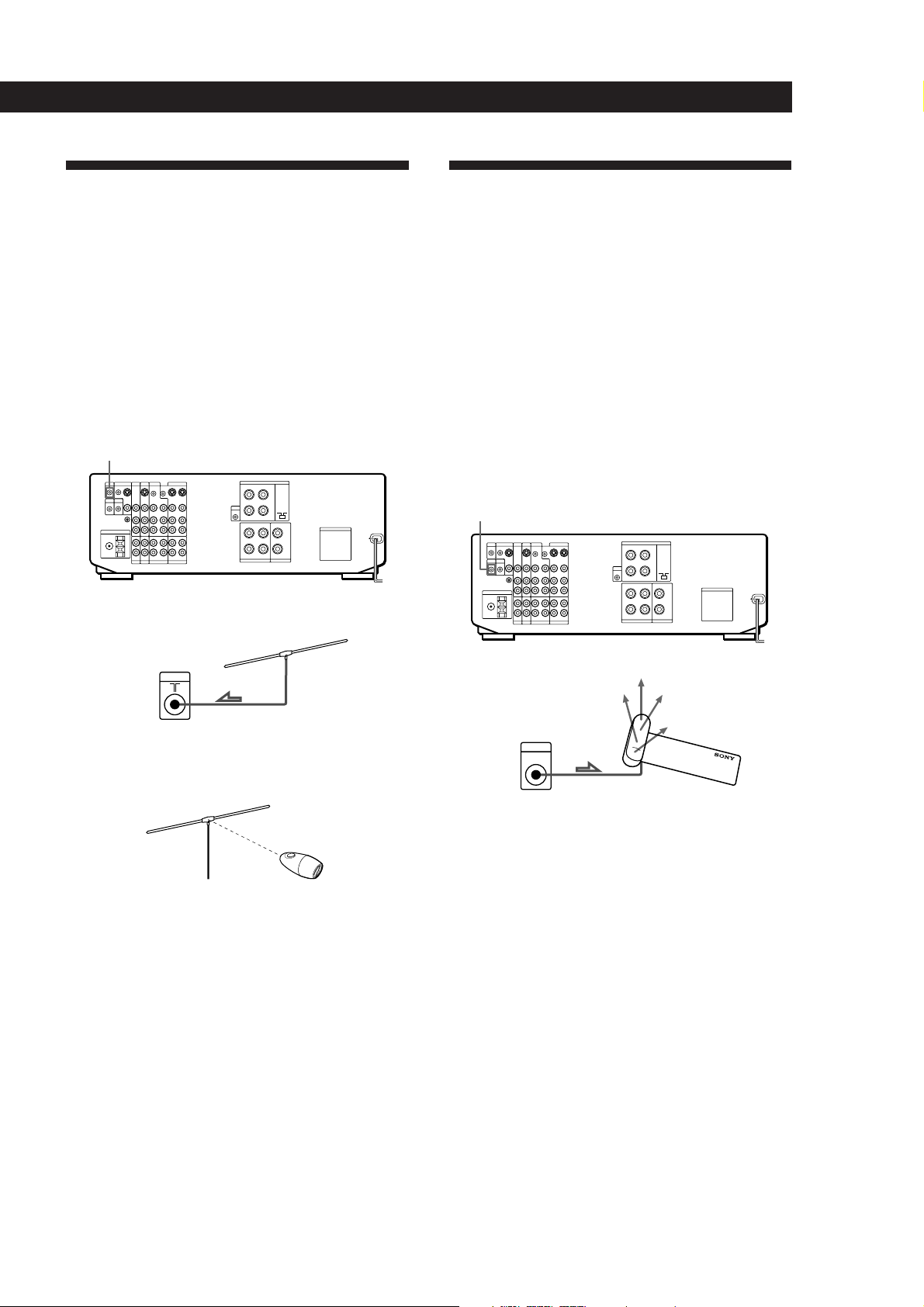
RC Antenna Hookups
(STR-DE905G only)
Overview
This section describes how to connect the supplied RC
antenna to the receiver. Since the remote controls the
unit using radio frequency (RF) signals, you must
connect the remote control (RC) antenna to the unit
before you can use the remote commander.
For the specific location of the terminal, see the
illustration below.
RC ANT
Hookups
IR Repeater Hookups
Overview
This section describes how to connect the supplied
extra infrared (IR) repeater to the receiver. The repeater
emits infrared signals corresponding to those emitted
by the remote controls supplied with the respective
components. Connected this repeater to obtain
additional coverage if you experience difficulty
controlling a certain component using the receiver’s on
screen display (OSD) control functions, or your
installation prevents the repeater on the front panel
from reaching all of the equipment you need to control.
For the specific location of the terminal, see the
illustration below.
IR OUT
Receiver
RC ANT
To maximize RF signal transmission efficiency:
• Position the RC antenna perpendicular to the signal path
of the remote (see below).
• Operate the remote within about 24 feet (about 7 m) of the
RC antenna.
If you have difficulty operating the on-screen display
within this range, reposition the RC antenna for better
reception.
• Keep the RC antenna at least 20 inches (about 50 cm) away
from metallic objects.
RC antenna
Hookups
Receiver
IR OUT
Notes
• Use the supplied adhesive tape to secure the IR repeater
so that its front faces the equipment to be controlled.
• If you experience trouble controlling the connected
equipment, the infrared (IR) signals transmitted from the
repeater may not be reaching the infrared receptor on the
respective equipment. In such a case, reposition the IR
repeater closer to that piece of equipment.
IR repeater
9
Page 10
Getting Started
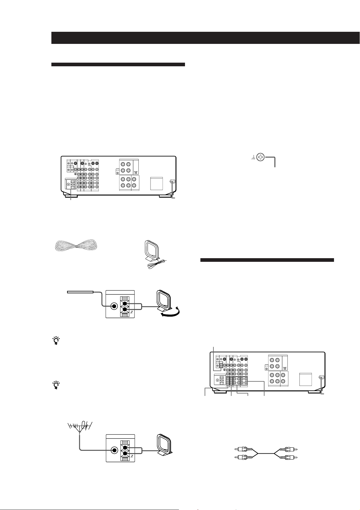
Antenna Hookups
Note
To prevent noise pickup, keep the AM loop antenna away
from the unit and TV set.
Overview
This section describes how to connect AM and FM
antennas to the receiver. If you want to receive radio
broadcasts with the receiver, complete these
connections first, then go to the following pages.
For specific locations of the terminals, see the
illustration below.
ANTENNA
What antennas will I need?
• FM wire antenna
(supplied) (1)
• AM loop antenna
(supplied) (1)
Hookups
Connecting a ground wire
To prevent hum, connect a ground wire (not supplied)
to the y ground terminal. If you’ve connected an
outdoor antenna, be sure to connect the ground for
lightning protection.
Receiver
.
to ground
Where do I go next?
If you want to connect other components, go on to the next
section. If you’re only planning to use the receiver to listen
to the radio, go to “Speaker System Hookups” starting on
page 11.
Audio Component Hookups
FM wire antenna
After connecting
the wire antenna,
Receiver
ANTENNA
FM
75Ω
COAXIAL
AM loop antenna
AM
keep it as horizontal
as possible.
Adjust the
direction.
If AM reception is poor
We recommend that you purchase and connect the
optional Sony antenna to the unit if reception is
weakened by ferroconcrete used in the construction of
your apartment or building.
If you have poor FM reception
Connect a 75-ohm coaxial cable (not supplied) to an FM
outdoor antenna.
FM outdoor antenna
Receiver
ANTENNA
FM
75Ω
COAXIAL
AM loop antenna
AM
Overview
This section describes how to connect your audio
components to the receiver. If you want to use the
receiver as an amplifier, complete these connections.
For specific locations of the jacks, see the illustration
below.
CTRL A1
PHONO DAT/MDCD TAPE
What cords will I need?
Audio cords (not supplied) (1 for each CD player and
turntable; 2 for each tape deck, DAT deck, or MD deck)
White (L)White (L)
Red (R)
Red (R)
10
Page 11
Hookups
The arrow ç indicates signal flow.
CD player
CD player
OUTPUT
LINE
Tape deckReceiver
OUTPUT
DAT/MDReceiver
OUTPUT
Tape deck
DAT/MD
Receiver
L
R
L
R
L
R
TAPE
DAT/MD
IN
CD
INREC OUT
INREC OUT
L
R
INPUT
LINELINE
INPUT
LINELINE
Getting Started
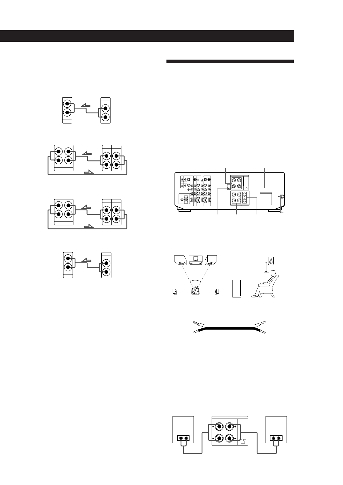
Speaker System Hookups
Overview
This section describes how to connect your speakers to
the receiver. Although front (left and right) speakers
are required, center and rear speakers are optional.
Adding center and rear speakers will enhance the
surround effects. Connecting an active woofer will
increase bass response.
For specific locations of the terminals, see the
L
R
L
R
illustration below.
WOOFER REAR
FRONT SPEAKERS
SPEAKERS
IMPEDANCE
SELECTOR
CENTER
SPEAKER
Turntable
Receiver Turntable
L
R
IN
PHONO
OUTPUT
LINE
L
R
• If your turntable has an earth lead
To prevent hum, connect the earth lead to the y ground
terminal on the receiver.
CONTROL A1 Hookups
• If you have a CONTROL A1 compatible Sony CD player
or tape deck
Use a CONTROL A1 cord (not supplied) to connect the
CTRL A1 jack on the CD player or tape deck to the S-LINK
CTRL A1 jack on the receiver. Refer the separate manual
“CONTROL-A1 Control System” and the Operating
Instructions supplied with your CD player or tape deck
for details.
• If you have a Sony CD changer with a COMMAND
MODE selector
If the CD changer’s COMMAND MODE selector can be
switched between CD 1, CD 2, and CD 3, be sure to set the
command mode to “CD 1” and connect the changer to the
CD terminals on the receiver.
However, if you have a Sony CD changer with VIDEO
OUT terminals, set the command mode to “CD 2” or “CD
3” and connect the changer to a set of the receiver’s video
component terminals (VIDEO 1, VIDEO 2, or LD).
For optimum surround sound effect, place your
speakers as shown below.
Rear speaker
60 - 90 cm
45°
Front speaker
What cords will I need?
Speaker cord (not supplied) (1 for each speaker)
(+)
(–)
(+)
(–)
Twist the stripped ends of the cord about 2/3 inch (15 mm).
Be sure to match the speaker cord to the appropriate
terminal on the components: + to + and – to –. If the cords
are reversed, the sound will be distorted and will lack bass.
Hookups
Front speakers
Front speaker
(R)
} ]
Receiver
FRONT SPEAKERS
RL
Front speaker
(L)
} ]
(continued)
11
Page 12
Getting Started
L
R
L
R
TV/DBS
OUTPUT
VIDEO
IN
AUDIO
IN
VIDEO
AUDIO
MONITOR
OUT 1
INPUT
VIDEO
OUT
CTRL S
IN
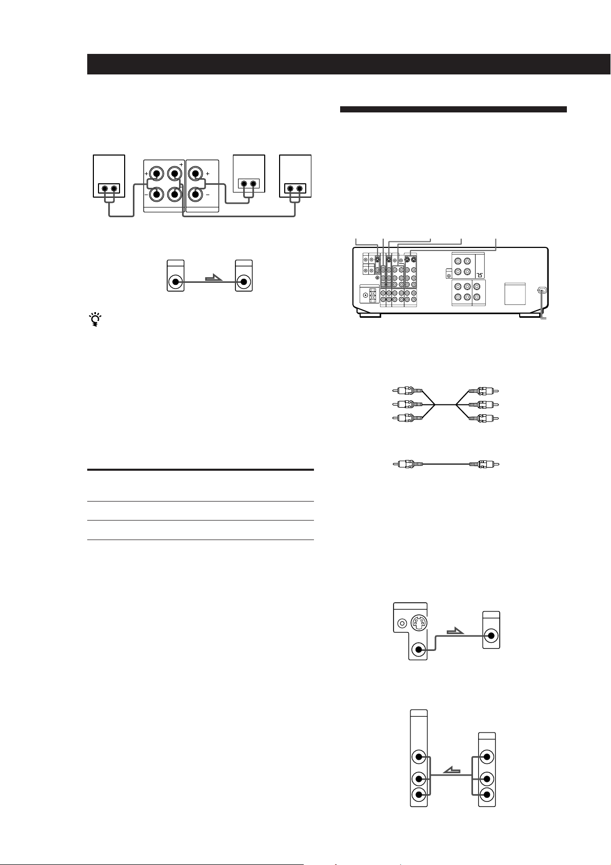
Rear and center speakers
Rear
speaker
(R)
Receiver
R
} ]} ]
REAR SPEAKERSLCENTER SPEAKER
Center
speaker
} ]
Rear
speaker
(L)
TV/VCR Hookups
Overview
This section describes how to connect video
components to the receiver. For specific locations of the
jacks, see the illustration below.
Active woofer
Receiver
AUDIO
OUT
Active woofer
INPUTMIX
If your TV monitor uses separate speakers
You can connect one of them to the SURROUND OUT
CENTER terminal for use with Dolby Pro Logic
Surround Sound (see page 32).
Selecting the impedance
Set the IMPEDANCE SELECTOR for the front speakers
as indicated in the table below. Check the instruction
manual of your speakers if you’re not sure of the
impedance. (This information is usually printed on a
label on the back of the speaker.)
if nominal impedance of
your speaker is
Between 4 and 8 ohms
8 ohms or higher
Set IMPEDANCE SELECTOR to
4 Ω
8 Ω
VIDEO 1VIDEO 2LDMONITOR TV/DBS
What cables will I need?
• Audio/video cable (not supplied) (1 for each TV or LD
player; 2 for each VCR)
Yellow
White (L)
Red (R)
Yellow
White (L)
Red (R)
• Video cable (not supplied) (1 for a TV monitor)
Yellow
Yellow
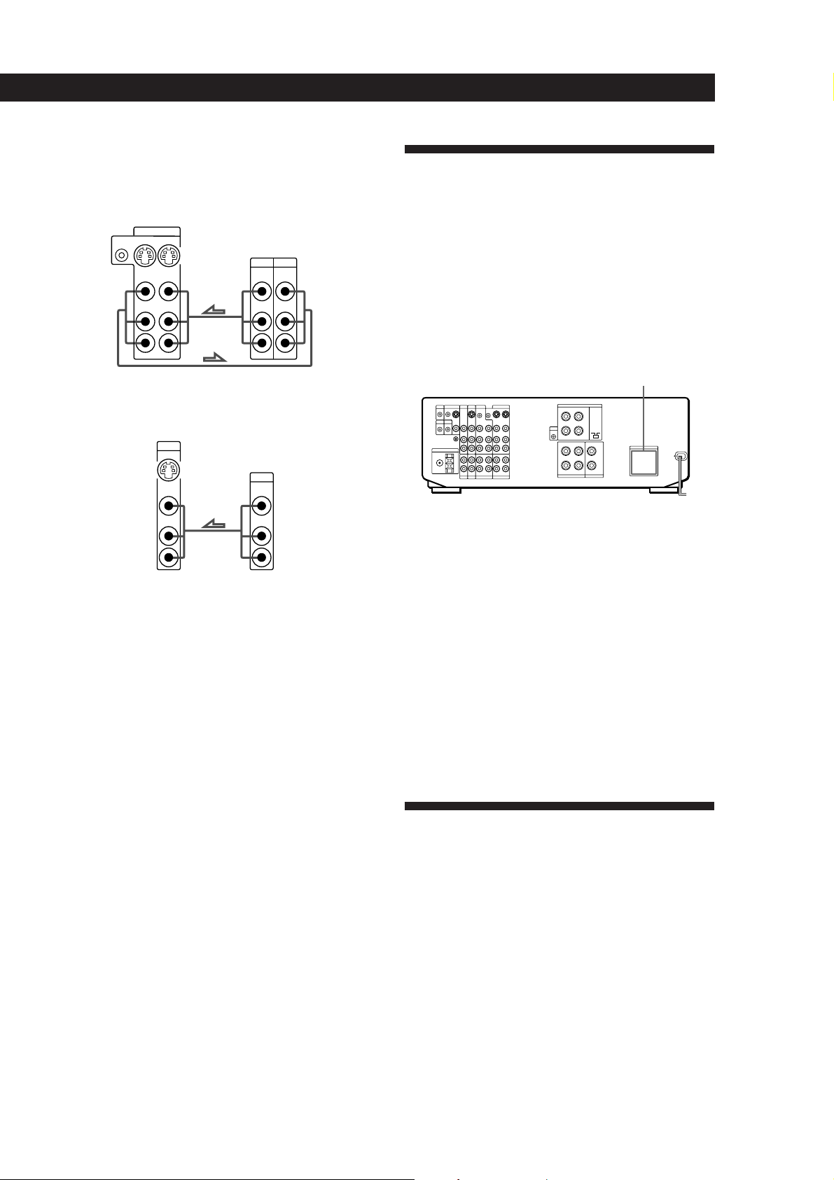
Hookups
The arrow ç indicates signal flow.
Monitor
If you are using your TV as a monitor, do not connect
anything to the TV/DBS IN jacks, unless you have a
Sony TV with TV OUT jacks (see page 25 for details).
Receiver
TV
TV tuner or DBS (Digital Broadcasting Satellites) receiver
Receiver
TV/DBS
12
Page 13
VCR (via the VIDEO 1 jacks)
If you have two VCRs connect the second one to the VIDEO
2 jacks. If one of them has a StarSight tuner, be sure to
connect that one to the VIDEO 1 jacks.
Receiver
VIDEO 1
CTRL S
IN
INOUT
VIDEO
VIDEO
IN
OUT
AUDIO
AUDIO
IN
OUT
L
R
VCR
OUTPUT
VIDEO VIDEO
AUDIO AUDIO
INPUT
L
R
LD player
Receiver
LD
IN
VIDEO
IN
AUDIO
IN
L
R
LD
OUTPUT
VIDEO
AUDIO
L
R
• If you have a CONTROL S compatible Sony TV, DBS
receiver, monitor, VCR or LD player
Use a CONTROL S cord (supplied) to connect the CTRL S
IN (for TV, DBS tuner, or monitor) or OUT (for VCR or LD
player) jack on the receiver to the appropriate S-LINK jack
on the respective component. Refer to the Operating
Instructions supplied with your TV, DBS receiver,
monitor, VCR, or LD player for details.
Getting Started
AC Hookups
Connecting the AC power cord
Connect the AC power cord from this receiver and
from your audio/video components to a wall outlet.
If you connect other audio components to the
SWITCHED AC OUTLET(s) on the receiver, the
receiver can supply power to the connected
components so you can turn on/off whole system
when you turn on/off the receiver.
SWITCHED AC OUTLET(s)
/
to a wall
outlet
Caution
Make sure that the power consumption of the component(s)
connected to the receiver’s AC outlet(s) does not exceed the
wattage indicated on the rear panel. Do not connect highwattage electrical home appliances such as electric irons,
fans, or TVs to this outlet.
Where do I go next?
Before you use the␣ receiver, go to the next section to make
sure that all the controls are set to the appropriate positions.
Where do I go next?
Go on to the next section to connect an AC plug and
complete your home theater system.
Before You Use Your Receiver
Before you start using your receiver, make sure that
you have:
• Turned MASTER VOLUME to the leftmost
position (0).
• Set the speakers to ON. (For details, see page 44.)
13
Page 14
Preparing and Using the Remote
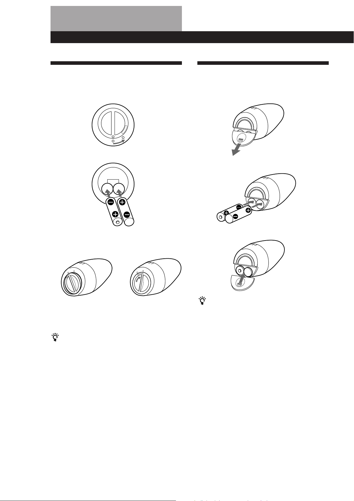
Inserting Batteries Into the
Remote: STR-DE905G
1 Open the cover on the bottom of the remote.
O
P
E
N
÷
2 Insert two size -AA (R6) batteries with correct
polarity (+/–).
3 Close the cover by holding it down (it will be a
little uneven) and turning it to the right.
The cover locks
Inserting Batteries Into the
Remote: STR-DE805G
1 Open the cover on the bottom of the remote.
2 Insert two size -AA (R6) batteries with correct
polarity (+/–).
3 Close the cover.
14
÷
After inserting the batteries into the remote
Place it undisturbed on a flat surface for about 10
seconds to allow the internal circuitry to calibrate.
To avoid damage caused by battery leakage and
corrosion
Remove the batteries when the commander will not be
used for a long time.
Battery life
• Normal operation can be expected about three
months using Sony SUM-3 (NS), and a half year
using Sony AM-3 (NW) alkaline batteries. Since the
remote consumes power whenever you pick it up
and an on-screen display appears, the service life of
the batteries may be less than three months,
depending on how much you handle the remote.
• When the batteries become weak, LOW will appear
on the display during the initial on-screen displays
(but possibly not at the deeper menu levels). When
EMPTY appears, the batteries are almost completely
drained and will soon need to be replaced.
To avoid damage caused by battery leakage and
corrosion
Remove the batteries when the commander will not be
used for a long time.
Battery life
• Normal operation can be expected about three
months using Sony SUM-3 (NS), and a half year
using Sony AM-3 (NW) alkaline batteries. Since the
remote consumes power whenever you pick it up
and an on-screen display appears, the service life of
the batteries may be less than three months,
depending on how much you handle the remote.
• Do not expose the remote sensor to direct sunlight or
lighting apparatuses. Doing so may cause a
malfunction.
Page 15
Preparing and Using the Remote
Preventing Interference
Between Multiple Remotes
(STR-DE905G only)
If you use two or more receivers at the same time,
interference may occur between the RF signals, causing
the units to operate erratically. You can prevent this by
giving all units a unique security number which
distinguishes the signal of each unit from the others.
Follow the procedure below to assign a security
number to each unit.
1 Turn off the power to the unit.
2 Turn on the unit again while simultaneously
holding down the PHONO, CD, and TUNER
buttons on the front panel. “SECURITY No.”
appears in the display. Enter a number from 0 to
15 by pressing PHONO, CD or TUNER on the
front panel. Make sure that the number is
different from the security code of the other units.
3 After a few seconds, “SECURITY OK!” appears,
indicating that the code has been recorded.
SECURITY
NO.
0
1
2
3
4
5
6
7
Remote
commander
4321
4321
4321
4321
4321
4321
4321
4321
SECURITY
NO.
8
9
10
11
12
13
14
15
How to Use the Remote:
Remote
commander
4321
4321
4321
4321
4321
4321
4321
4321
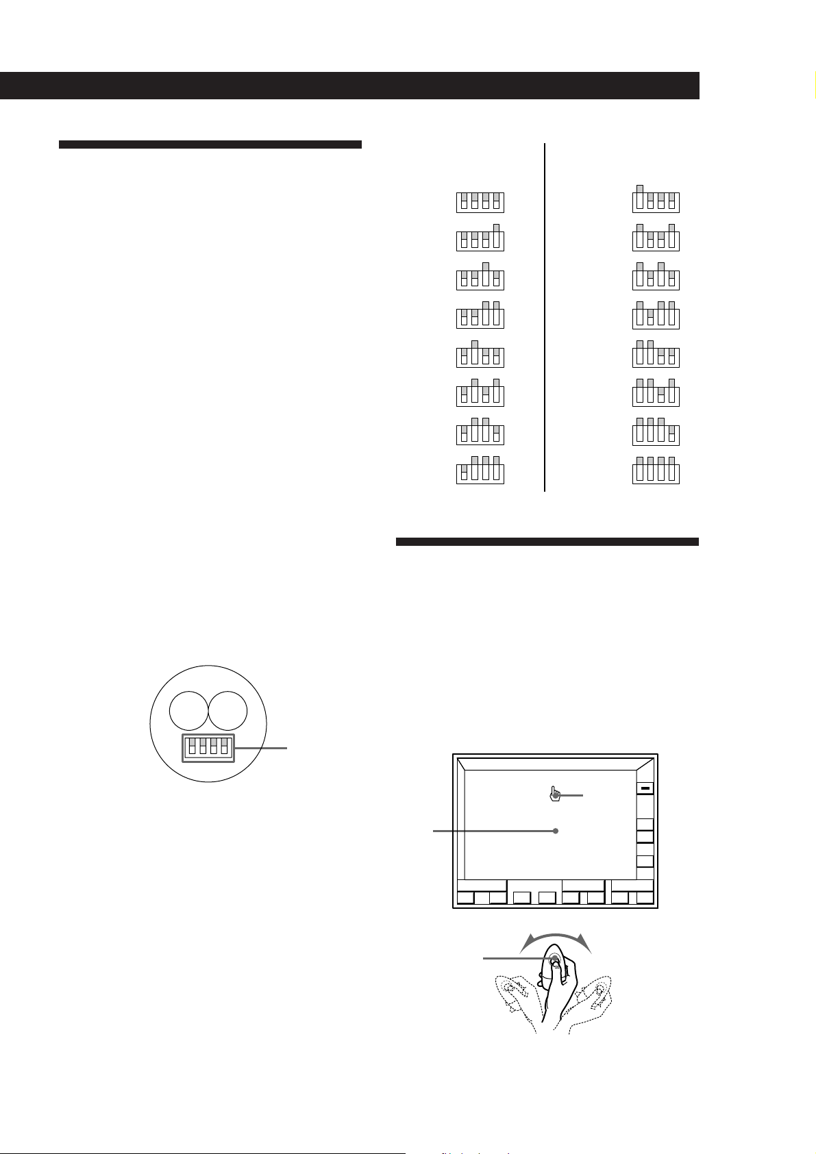
4 Enter the same security number into the remote.
To do this, open the battery compartment and
remove the batteries. You will see a set of yellow
switches as shown below.
Yellow
switches
Use the tip of a pen or some other pointed object
to flip up the appropriate switches for each digit
of the security number (refer to the chart on the
following page). Note that all switches are down
for zero, and all switches are up for fifteen.
5 Reinsert the batteries and place the remote on a
flat surface for about 10 seconds.
STR-DE905G
The supplied remote lets you perform almost all of the
receiver operations. Operation is simple, just move the
remote in the direction you want to move the pointer
(hand shaped icon) on the on-screen display. Position
the pointer so that the finger tip is positioned on one of
the on-screen items, then press and quickly release the
button on the remote to “click” the item.
Blank
area
Click button
FUNCTION
S
O
U
N
D
()0pP=+
Pointer
ALL
OFF
VOL
+
–
USERSUB
To turn on the receiver
Press the click button on the remote once or twice to turn on
the unit.
(continued)
15
Page 16
Preparing and Using the Remote
()0pP=+
FUNCTION
+
–
VOL
ALL
OFF
USERSUB
S
O
U
N
D
PUSH
ENTER
Mm
Â
µ
If the on-screen display does not appear even after the
batteries have been inserted into the remote (see page
14), reinsert the batteries and place the remote on a flat
surface for about 10 seconds.
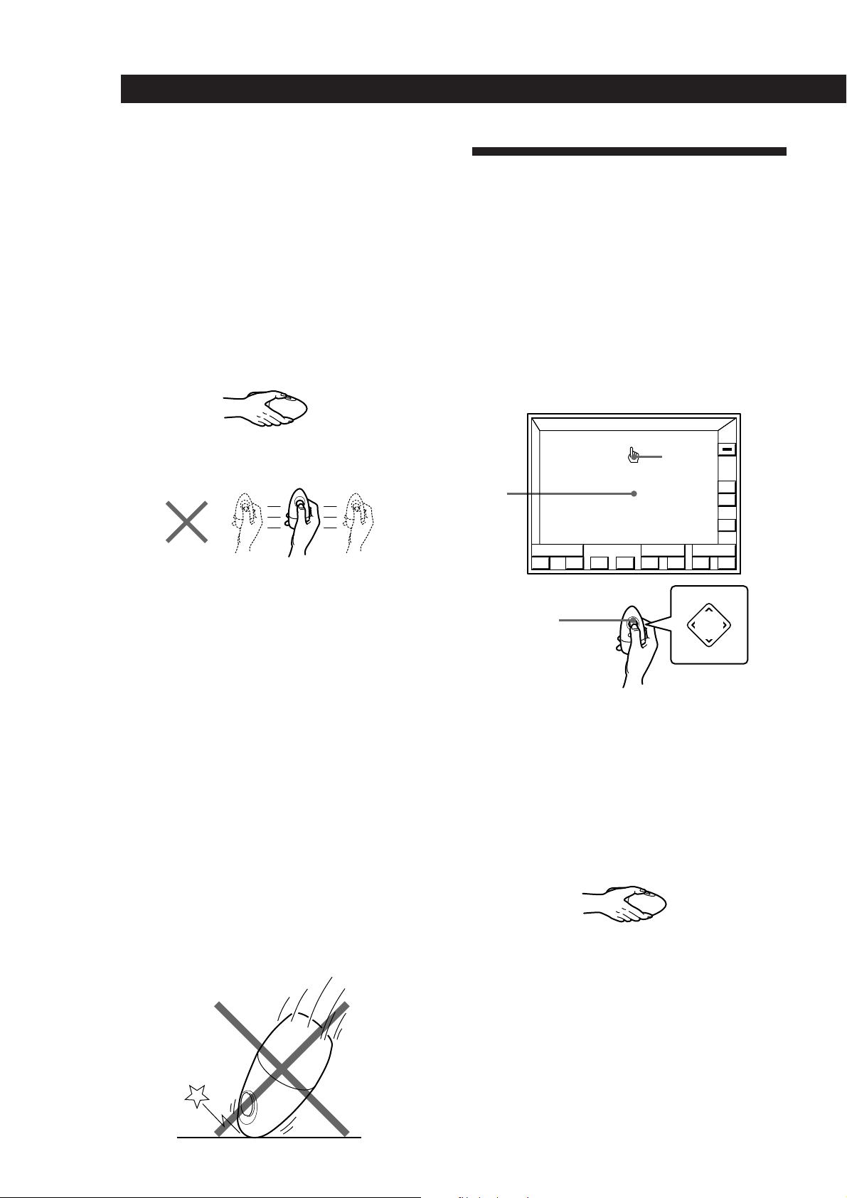
Hints on handling the remote
• A slight wrist movement is all you need to direct the
pointer. (See previous illustration.)
• Hold the remote with its “click” button facing up, as
shown below. If the click button is oriented
diagonally, the pointer will not move in the same
direction that you move the remote.
How to Use the Remote:
STR-DE805G
The supplied remote lets you perform almost all of the
receiver operations. Operation is simple, press the
direction control button on the remote once to recall
the on-screen display, then press the corner of the
direction control pad representing the direction you
want to move the pointer (hand shaped icon) on the
on-screen display. Position the pointer so that the
finger tip is positioned on one of the on-screen items,
then press and quickly release the center of the
direction control button to “click” the item.
• The pointer will not move if you move the remote
along a flat plane as shown below.
• The on-screen display disappears automatically after
a few seconds when you place the remote on a flat
surface.
To make the on-screen display disappear faster,
position the pointer in the blank area, hold down the
click button to vanish the display, then place the
remote on a flat surface and release the click button.
To recall the on-screen display, pick up the remote.
Notes
• The position of the pointer freezes when you hold down
the click button.
• If the pointer begins drifting on the screen even while the
remote is stationary, place the remote on a flat surface
until the on-screen display disappears. The pointer
should behave normally the next time you use the remote.
• If your hand is very dry, the on-screen display may not
appear when you touch the click button. In this case, press
the click button.
Pointer
Blank
area
Direction
control
button
To turn on the receiver
Press the direction control button on the remote once or
twice to turn on the unit.
Hints on handling the remote
• Hold the remote with its direction control button
facing up, as shown below.
Caution
Since the remote contains delicate circuitry and parts, do not
subject it to sudden changes in temperatures or to shock.
• To make the on-screen display disappear, position
the pointer in the blank area, and press the center of
the direction control button.
16
Page 17

Registering a TV or Monitor
Registering a Sony TV or monitor
If your Sony TV can be controlled by an infrared
remote, and it is connected to the receiver by it’s
VIDEO 1 video input jack, IR code registration is
unnecessary.
Preparing and Using the Remote
4 Click OTHER TV (or click “Sony TV” for a Sony
TV).
TV MONITOR SET
TV IR SET
TV INPUT
TV SIZE
GRAPHIC POSITION
Sony TV
OTHER TV
VIDEO
1
NORMAL WIDE
32
The following cases require registration of a Sony TV
• If your Sony TV is connected via a different video
input jack (such as VIDEO 2).
To ensure proper operation, follow steps 1 to 3 below,
click VIDEO 1 2 3 to specify the correct video input in step
4, then click RETURN or EXIT.
• If you are using a wide Sony TV.
To ensure proper operation, follow steps 1 to 3, click
WIDE in step 4, then click RETURN or EXIT.
Registering a non-Sony TV or monitor
Complete the following procedure to set the receiver to
turn on your TV or monitor automatically whenever
you turn on the receiver.
Registration
1 Turn on the receiver and the TV set.
Make sure the input selector on the TV set is set to
the video input.
2 Click FUNCTION in the main menu.
FUNCTION
ALL
OFF
RETURN
EXIT
If you connected the receiver to the VIDEO 2, or 3
jacks on your TV or monitor
Click VIDEO 1 2 3 to specify the correct video input.
If you are using a wide TV
Click WIDE to specify WIDE.
If you are using a Sony TV
The IR codes are programed automatically and
registration is complete (click RETURN or EXIT).
Before going to step 5, cover the IR sensor on the
TV to prevent accidental operation. Otherwise,
the on-screen display may be turned off during
the programing procedure.
5 Click START.
TV MONITOR SET
TV IR SET
TV INPUT
TV SIZE
GRAPHIC POSITION
Sony TV
OTHER TV
START
VIDEO
1
NORMAL WIDE
32
S
O
U
N
D
BAND
3 Click TV SET.
VIDEO 1 DAT/MD
VIDEO 2
VIDEO 3
L D
MACRO 1
TV SET
LIST
FM 102.50MHz
FUNCTION SELECT
STEREO
CD
TUNER
PHONO
TAPETV / DBS
MACRO 2
USERSUB
EXIT
VOL
+
–
+–
RETURN
EXIT
6 When “PUSH YOUR COMMANDER” appears on
the TV screen, press the button
that corresponds to the highlighted control button
(e.g., POWER).
TV IR SET
TV IR SET
PUSH YOUR COMMANDER
RETURN
on the TV's remote
TV POWER
VIDEO 1
CODE CLEAR
EXIT
(continued)
17
Page 18

Preparing and Using the Remote
When programing the IR code, point the remote
at the IR sensor on the receiver from a distance no
greater than 4 inches (10 cm) and hold down the
button on the remote for about 5 seconds until the
instruction “RELEASE YOUR COMMANDER”
appears.
IR sensor
Keep the remote pointed horizontally at the IR
sensor until the code is programed.
If you tilt or move the remote during the
programing process, the IR code may not be
programed correctly.
7 Repeat this procedure for the remaining buttons
that appear on the TV screen. If an IR code was
not programed correctly, the IR code setting
indicator will flash.
If your TV set’s remote has an independent input
selector button (e.g., VIDEO 1)
Program the IR code of this button when the VIDEO 1
button appears. When you turn on the receiver, the TV
switches to the video input automatically.
If your TV set does not have an independent input
selector button or has a cyclic input selector button
Click EXIT to return to the main menu.
The TV’s input can not be switched automatically when
you turn on the receiver. Switch the TV to the video
input manually. If you programed an IR code for the
VIDEO 1 button, follow the instructions in “To erase a
specific IR code” below to erase the VIDEO 1 code.
To erase TV IR codes
Click CODE CLEAR.
• To erase a specific IR code
1 Click SINGLE IR CODE CLEAR
2 Click the button you want to clear.
“Are you sure?” appears for confirmation.
3 Click YES to erase the code.
“CODE CLEAR!” appears in the display.
To stop before erasing a code, click NO.
To erase another code repeat steps 2 and 3.
• To erase all the TV IR codes
1 Click TV IR CODE CLEAR.
“Are you sure?” appears for confirmation.
2 Click YES to erase the codes.
“CODE CLEAR!” appears in the display. To stop before
erasing the codes, click NO.
• To erase all the IR codes.
1 Click ALL IR CODE CLEAR.
“Are you sure?” appears for confirmation.
2 Click YES to erase the codes.
“CODE CLEAR!” appears in the display. To stop before
erasing all the codes, click NO.
Note
Some IR codes may not have been successfully programed,
even if “RELEASE YOUR COMMANDER” appears on the
TV screen. In this case, try programing the IR code again. If
the IR code still cannot be programed, follow the procedure
described in “Programming Other Infrared (IR) Codes
(USER IR setting)” on page 22.
To change from another manufacturer’s TV set to a Sony
TV set
Connect the receiver’s MONITOR OUT jack to the VIDEO 1
input jack of the Sony TV set. Follow steps 1 to 3, then click
SONY TV in step 4. Click VIDEO 1 2 3 and/or WIDE to
specify VIDEO 1 and/or WIDE if necessary. Then click
RETURN or EXIT.
18
To exit to the main menu
Click EXIT.
To return to a previous menu
Click RETURN.
Page 19

Registering Audio/Video
Equipment
Registering Sony audio/video equipment
If your Sony audio and video equipment can be
controlled by an infrared remote, simply connect them
to the jacks shown on the following table, registration
is unnecessary.
Receiver jacks Equipment to be connected
VIDEO 1 Sony VTR 3 (VHS)
VIDEO 2 Sony VTR 1 (BETA)
VIDEO 3 Sony VTR 2 (8 mm)
LD Sony LD player
TV/DBS Sony DBS receiver
DAT/MD Sony DAT deck
CD Sony CD player (CD 1)
TAPE Sony Tape deck
MONITOR Sony TV (via its VIDEO 1 jack)
Preparing and Using the Remote
Registering non-Sony audio/video
equipment
If you connect audio or video equipment made by
another manufacturer, you must program the IR codes
used by the equipment before you can control it
through the receiver.
You can program up to 120 IR codes, including user IR
codes; however, depending on the type of codes
recorded, the maximum limit may be less than 100. It
may be difficult or impossible to program up to 120
codes under the following conditions:
• When programing IR codes of special remotes such
as card type remotes, or remotes for household
appliances such as air conditioners.
• When programing from remotes with weak batteries.
• When programing IR codes that have been
programed to a programmable remote (i.e., any IR
code not originally supplied in the respective
remote).
Registration
Click FUNCTION in the main menu.
1
FUNCTION
ALL
OFF
The following cases require registration of Sony products
• When connecting a Sony MD deck to the DAT/MD
jacks.
• When connecting a Sony audio product with
CONTROL-A1 compatibility.
• When connecting a Sony product to jacks other than
those specified in the previous table (e.g., when
connecting a Sony LD player to the VIDEO 3 jacks).
• When exchanging non-Sony audio or video
equipment with a Sony product.
Notes
• If your VCR has a COMMAND CODE selector switch (for
VTR1, VTR2, or VTR3), set the switch to the applicable
setting. If your VCR has a built-in StarSight tuner, you
must set the COMMAND CODE selector switch to VTR 3.
• If your CD changer has a COMMAND MODE selector
switch (for CD 1, CD 2, or CD 3), normally it should be set
to “CD 1”. However, if your CD changer has VIDEO OUT
terminals, set the command mode to “CD 2” or “CD 3”
(“CD 3” should only be used when making CONTROL-A1
connections).
S
O
U
N
D
BAND
2 Click IR SET.
VIDEO 1 DAT/MD
VIDEO 2
VIDEO 3
L D
MACRO 1
IR SET
LIST
FM 102.50MHz
FUNCTION SELECT
STEREO
CD
TUNER
PHONO
TAPETV / DBS
MACRO 2
VOL
+
–
USERSUB
+–
EXIT
(continued)
19
Page 20

Preparing and Using the Remote
3 Click the appropriate function.
IR CODE SETTING
VIDEO 1 Sony VTR3
VIDEO 2
VIDEO 3
LD
TV/DBS
DAT/MD
CD Sony CD1
TAPE Sony TAPE
RETURN
Sony VTR1
Sony VTR2
Sony LD
Sony DBS
Sony DAT
EXIT
4 Click “Sony” for a Sony product or OTHER for a
non-Sony product.
IR CODE SETTING
OUTPUT IR
Sony
RETURN
OTHERMAKER
EXIT
If the program source is a Sony product
The IR codes are programed automatically and
registration is complete (click RETURN or EXIT).
To take advantage of CONTROL-A1 compatible audio
components, such as multi-disc CD players, click
CONTROL-A1 to select CONTROL-A1.
5 Click the respective program source.
IR CODE SETTING
OUTPUT IR
VCR
RETURN
Sony
TV
LD
CD
OTHERMAKER
TAPE
DAT
MD
EXIT
If the equipment is not a video deck or laser disc
player
Cover the IR sensor on the equipment to prevent
accidental operation during the programing procedure,
click START, then go to step 6.
IR CODE SETTING
OUTPUT IR
VCR
RETURN
Sony
TV
LD
CD
START
OTHERMAKER
TAPE
DAT
MD
EXIT
If the equipment is a video deck or laser disc player:
1 Click START.
A list of other manufacturers appears.
2 Click the manufacturer of the respective equipment
and the IR codes for that program source are
registered automatically. (If the manufacturer is not
listed, cover the IR sensor on the equipment to
prevent accidental operation during the programing
procedure, click “OTHER”, then go to step 6).
3 Click TEST.
If the selected program source turns on, it means the
IR codes have been registered. This ends the
procedure.
If the program source does not turn on, click the
number button beside the manufacturer’s name to
select another number, then click TEST again. If the
program source still does not turn on, cover the IR
sensor on the equipment to prevent accidental
operation during the programing procedure, click
“OTHER”, click “OTHER”, then go to step 6.
6 When “PUSH YOUR COMMANDER” appears on
the TV screen, press the button
video equipment’s remote that corresponds to the
control button highlighted on the TV screen.
is the POWER switch.
IR CODE SETTING
on your audio/
20
1 9 2
10/0
PUSH YOUR COMMANDER
RETURN
)(0pP=+
3
4
>10
5 6 7 8
REC
CODE CLEAR
EXIT
When programing the IR code, point the remote
at the IR sensor on the receiver from a distance no
greater than 4 inches (10 cm) and hold down the
Page 21

Preparing and Using the Remote
button on the remote for about 5 seconds until the
instruction “RELEASE YOUR COMMANDER”
appears and the IR code setting indicator turns
off.
IR sensor
Keep the remote pointed horizontally at the IR
sensor until the code is programed.
If you tilt or move the remote during the
programing process, the IR code may not be
recorded correctly.
Repeat this procedure for the remaining buttons
After you’ve programed all the IR codes, the IR CODE
SETTING menu reappears.
To program special IR codes that do not appear as
on-screen controls
See “Programming Other Infrared (IR) Codes (USER IR
setting)” on page 22.
If the IR codes do not operate as expected
• Perform the programing operation(s) again to make sure
the IR codes were programmed correctly.
• If you experience difficulty operating the INPUT, number,
or ENTER buttons of a video deck or laserdisc player after
automatic registration from the manufacturer list in step 5.
Program the IR codes for that equipment manually as
shown in step 6.
• On some laser disc players made by other manufacturers,
the ) and 0 buttons may not operate correctly even
after automatically registration from the manufacturer list
in step 5. If this happens, perform step 6 to manually
program the IR codes for the ) and 0 buttons, as well
as any other buttons that you want to use with the laser
disc player.
• If you register a playback source as TOSHIBA 2 or RCA 2,
you cannot turn the TV set on or off using the receiver’s
remote (the power will not go on when you click TEST).
• Some IR codes may not have been successfully
programed, even if “RELEASE YOUR COMMANDER”
appears on the TV screen. In this case, try programing the
IR code again. If the IR code still cannot be programed,
follow the procedure described in “Programming Other
Infrared (IR) Codes (USER IR setting)” on page 22.
• The unit may not be able to record IR codes with special
waveforms produced on some remotes.
7 Repeat steps 3 to 6 to program IR codes from
other program sources.
To exit to the main menu
Click EXIT.
To return to a previous menu
Click RETURN.
To erase IR codes
Click CODE CLEAR.
• To erase a specific IR code
1 Click SINGLE IR CODE CLEAR
2 Click the button you want to clear.
“Are you sure?” appears for confirmation.
3 Click YES to erase the code.
“CODE CLEAR!” appears in the display.
To stop before erasing a code, click NO.
To erase another code repeat steps 2 and 3.
• To erase all the IR codes for the current component (e.g.,
OTHER CD).
1 Click (OTHER CD) CODE CLEAR.
“Are you sure?” appears for confirmation.
2 Click YES to erase the codes.
“CODE CLEAR!” appears in the display.
To stop before erasing the codes, click NO.
• To erase all the IR codes.
1 Click ALL IR CODE CLEAR.
“Are you sure?” appears for confirmation.
2 Click YES to erase the codes.
“CODE CLEAR!” appears in the display.
To stop before erasing all the codes, click NO.
Notes
• Do not register the same type of component (i.e., an LD
player) at several different functions.
• The unit emits an IR signal that cancels the automatic
playback function of program sources, such as laser disc
and CD players, designed to start playing the moment
they are turned on. To activate the auto play feature, set
the receiver’s AUTO PLAY function to on.
• Keep the infrared sensor away from fluorescent light or
direct sunlight. Otherwise, the IR codes may not be
recorded.
• Even if the power cord has been disconnected from the
AC power outlet, recorded IR codes will stay in the
memory for approximately two weeks. If they disappear,
“ALL CLEAR!” will appear on the TV screen the next time
you turn on the receiver.
• Do not operate the remote supplied with the STR-DE805G
when “PUSH YOUR COMMANDER” appears on the TV
screen in step 6. Programing IR codes from the supplied
remote may cause the STR-DE805G to malfunction.
21
Page 22

Preparing and Using the Remote
Programming Other Infrared
(IR) Codes (USER IR setting)
Use the USER IR CODE SETTING menu to program
any IR codes that could not be programed in
“Registering Audio/Video Equipment”. These can
include codes for audio and video equipment, as well
as other types of equipment, made by almost any
manufacturer. The following procedure lets you to
program up to 20 USER IR codes.
To switch between upper and lower case letters
Click CAPS.
If you make a mistake
Click ? or / to move the cursor to the character to be
changed, then click the correct character (or click the
space bar to erase the character).
5 After entering the name, click RETURN to go back
to the USER IR CODE SETTING menu.
Repeat steps 3 through 5 until you enter the
names of all the IR codes you want to program.
1 Click FUNCTION in the main menu.
2 Click USER IR.
FUNCTION SELECT
VIDEO 1 DAT/MD
VIDEO 2
VIDEO 3
L D
MACRO 1
USER IR
CD
TUNER
PHONO
TAPETV / DBS
MACRO 2
EXIT
3 Click A B C D to select a user IR code page, then
click INDEX.
USER IR CODE SETTING
A B C D
INDEX
RETURN
EXIT
6 Click the name of the first IR code.
USER IR CODE SETTING
LIGHT 1
LIGHT 2
LIGHT 3
LIGHT 4
RETURN
A B C D
EXIT
Before going to step 7, cover the IR sensor on the
respective equipment to prevent accidental
operation during the programing procedure.
7 Click on START.
When “PUSH YOUR COMMANDER” appears on
the TV screen, press the button you want to
program.
USER IR CODE SETTING
LIGHT 1
LIGHT 2
LIGHT 3
LIGHT 4
A B C D
INDEX
START
22
4 Spell out a name for the IR code by clicking each
character in order. The name is stored
automatically.
USER IR CODE SETTING
A
B
F
G
K
L
P
Q
U
V
CAPS
RETURN
To enter a space
Click the space bar.
W
C
D
H
M
R
E
I
J
N
O
S
T
X
Y
bB
1
2
5
8
0
–
EXIT
3
6
9
*
+
4
7
/
Z
PUSH YOUR COMMANDER
RETURN
CODE CLEAR
EXIT
When programing the IR code, point the remote
at the IR sensor on the receiver from a distance no
greater than 4 inches (10 cm) and hold down the
button on the remote for about 5 seconds until the
instruction “RELEASE YOUR COMMANDER”
appears and the IR code setting indicator turns
off.
IR sensor
Page 23

Keep the remote pointed horizontally at the IR
sensor until the code is programed.
If you tilt or move the remote during the
programing procedure, the IR code may not be
programed correctly.
Repeat this procedure for the remaining buttons
After you’ve programed all the IR codes, the IR CODE
SETTING menu reappears.
To reprogram a specific IR code.
Click the button where the IR code was programed, then
click START.
To Erase IR codes
Click CODE CLEAR.
• To erase one specific IR code
1 Click SINGLE IR CODE CLEAR
2 Click the button you want to clear.
“Are you sure?” appears for confirmation.
3 Click YES to erase the code.
“CODE CLEAR!” appears in the display.
To stop before erasing a code, click NO.
To erase another code repeat steps 2 and 3.
• To erase all the user IR codes.
1 Click USER IR CODE CLEAR.
“Are you sure?” appears for confirmation.
2 Click YES to erase the codes.
“CODE CLEAR!” appears in the display.
To stop before erasing the codes, click NO.
• To all the IR codes.
1 Click ALL IR CODE CLEAR.
“Are you sure?” appears for confirmation.
2 Click YES to erase the codes.
“CODE CLEAR!” appears in the display.
To stop before erasing all the codes, click NO.
Preparing and Using the Remote
Notes
• Even if the receiver’s power cord has been disconnected
from the AC power outlet, programed IR codes will stay
in the memory for approximately two weeks. If they
disappear, “ALL CLEAR” will appear on the TV screen
when you turn on the unit again.
• The power switch on some air conditioners use two
independent IR codes, even when there is only one switch.
If you cannot turn the air conditioner off with the IR code
programed for the on/off switch, repeat the procedure
and program the on and off IR codes separately.
• The operation of some air conditioner remote commanders
require two–way signal exchange with the air conditioner
itself. Though it is possible to program the IR codes of
such remote commanders in the unit, their use may not
result in normal air conditioner operation.
• The unit may not be able to register IR codes with special
waveforms produced on some remote commanders.
23
Page 24

Basic Operations
Selecting a Component
To exit to the main menu
Click EXIT.
To listen to or watch a connected component, go to the
function select menu and click on the program source
you desire.
Before you begin, make sure you have:
• Connected the RC antenna (STR-DE905G), IR
emitter, and all components securely and correctly as
indicated on pages 9 to 13.
• Registered the IR codes for the connected
components as indicated on pages 17 to 23.
• Turned MASTER VOLUME to the leftmost position
(0) to avoid damaging your speakers.
1 Pick up the remote and press the button once or
twice to turn on the receiver. Your TV should turn
on automatically, if not see pages 17 to 18 to
register your TV.
2 Click FUNCTION in the main menu.
FUNCTION
ALL
OFF
3 Click the component you desire.
The component starts playing automatically.
4 Click VOL + or – to adjust the volume.
To adjust the volume of the TV's speakers, use the
volume control on the TV.
FUNCTION
S
O
U
N
D
)(0pP=+
Control buttons
To operate the selected component
The control buttons at the bottom of the screen function as a
remote control for the selected component. Click the button
representing the operation you desire. Refer to the manual
supplied with the component you are controlling for details
regarding its operation.
To show other control buttons for the selected
component
Click SUB.
ALL
OFF
VOL
+
–
USERSUB
FUNCTION SELECT
VIDEO 1 DAT/MD
VIDEO 2
VIDEO 3
L D
MACRO 1
CD
TUNER
PHONO
TAPETV / DBS
MACRO 2
EXIT
To listen to or watch Click
Video tapes VIDEO 1, VIDEO 2
Laser discs LD
TV programs TV/DBS
Digital Audio Tapes (DAT) DAT/MD
or MiniDiscs (MD)
Compact Discs (CD) CD
Radio programs TUNER
Records PHONO*
Analog audio cassettes TAPE*
*1Control buttons do not appear when you select
phono.
*2The tape icon turns green during tape monitoring.
or VIDEO 3
1
2
To execute IR commands programed from other remotes
1 Click USER
2 Click A B C D repeatedly to display the command you
desire.
3 Click the button for the respective command.
To program IR codes from other remotes, see page 22.
To mute the sound
Click . The icon changes to and turns green.
“MUTE ON” then “MUTING” appear in the display on the
receiver. To turn the sound back on, click on the icon again.
To turn off the TV when listening to an audio source
Click in the bottom left corner. See “Remote Operation
of Audio Sources Without the TV (flasher)” on page 40 for
details regarding remote operation without the TV.
To turn off the selected component
Click in the bottom left corner.
To turn off all connected components
Click ALL OFF .
If you have components that turn on only when you press
the play button, they will not turn off you click ALL OFF
when the AUTO PLAY function (see page 41) is off. In this
case, click then on the play button (().
24
Page 25

Basic Operations
Notes
• The AUTO PLAY function is set at the factory to start
playing the component immediately after it is selected. To
turn AUTO PLAY off, see page 41.
• Components of the same type will be controlled
simultaneously by the on-screen controls.
For example, if you use the on-screen controls to start
playing one of two Sony laser disc players in the room, the
other will also start playing at the same time.
• If a component does not respond, it may be because IR
codes from the IR repeater are not fully reaching the
selected component source. If this happens, change the
position of the IR repeater or program source.
Watching Video programs
When you watch TV or video programs, we
recommend you play audio portion through the
receiver instead of your TV’s speaker. This lets you
take advantage of the receiver’s surround sound
effects, like Dolby Surround, and lets you use the
receiver’s remote to control the audio.
Turn off the speakers on your TV before you start so
you can enjoy the surround sound from your receiver.
Watching TV programs
You can use the TV tuner built in to your video deck to
watch TV programs using the receiver’s on-screen
operations.
1 Select the appropriate function (e.g. “VIDEO 2”).
2 Click TVb in the VCR controls at the bottom of the screen.
The control panels switches to the video decks’s TV
controls.
3 Click CH – or + to change the channel.
To return to the VCR controls, click VTRb.
We recommend switching to the VCR controls before
switching functions. If you leave directly from the TV
controls to the FUNCTION SELECT menu, the AUTO PLAY
(page 41) function will not operate the next time you select
the video deck as a program source.
Watching TV programs using a Sony TV (with TV OUT jacks)
When connecting a Sony TV with TV OUT jacks, connect the
TV OUT jacks to this unit’s TV/DBS IN jacks, then set the
TV/DBS function to “Sony TV”. This lets you watch TV
programs by selecting the TV/DBS function. Also, use the
TV’s VIDEO LABEL function to set the video input jack (e.g.,
VIDEO 1 IN) connected to this unit’s MONITOR OUT jack to
“RECEIVER”. If your Sony TV does not have TV OUT jacks,
refer to “Watching TV programs” above and use the TV
tuner built in to your video deck to watch TV programs.
Controlling a Sony DBS receiver
Before you can control the DBS receiver, the IR codes for the
function representing the DBS receiver must be set to “Sony
DBS”. The TV function is factory set to Sony DBS (to set a
different function to Sony DBS see page 19).
1 Select the appropriate function (e.g. TV)
2 Click TV /.
3 Click CURSOR MENU.
The DBS receiver control panel appears.
The icons in the cursor menu have the same function as
those on the DBS receiver (except for SELECT, which
substitutes for the enter button). Click the boarders at the
edge of the screen to move the DBS cursor.
To jump between the current and the previous channels,
click JUMP.
Controlling StarSight functions of a Sony VCR
Before you can control StarSight functions, the IR codes for
the function representing the StarSight tuner must be set to
“Sony VTR 3”. The VIDEO 1 function comes factory set to
“Sony VTR 3” (to set a different function to Sony VTR 3 see
page 19).
1 Select the appropriate function (e.g. “VIDEO 1”)
2 Click TV /.
3 Click STAR /.
The StarSight control panel appears.
Click the boarders at the edge of the screen to move the
StarSight cursor.
To change the video input of a Sony VCR
Click the INPUT icon in the video deck control panel.
To switch the screen size when using a wide TV monitor
Click to display the WIDE TV DISPLAY control panel,
then click the button for the display mode you desire.
This operation is only possible when “TV SIZE” in the TV
MONITOR SET menu is set to WIDE (see page 17).
Selecting a Component Using the Controls
on the Front Panel
1 Press POWER to turn on the receiver.
2 Press the button for the component you want to
use:
To listen to or watch Press
Video tapes VIDEO 1, VIDEO 2
or VIDEO 3
Laser discs LD
TV programs TV/DBS
Digital Audio Tapes (DAT) DAT/MD
or MiniDiscs (MD)
Analog audio cassettes TAPE MONITOR
Compact Discs (CD) CD
Radio programs TUNER
Records PHONO
3 Turn on the component, for example, a CD player,
and start playback.
When you listen with headphones
Connect the headphones to the PHONES jack and set
the SPEAKERS selector to OFF.
25
Page 26

Basic Operations
FM
50MH
Tuning and Presetting Radio
Stations
6 Click LIST to display the memory list.
BAND
FM 102.50MHz
SUB
STEREO
USERLIST
+–
This receiver lets you tune and preset radio stations
from the on-screen display. You can store up to 30 FM
or AM stations, and recall them later with a simple
click. To assign names to the preset stations, see page
35.
Before you begin, make sure you have:
• Connected the RC antenna securely and correctly as
indicated on page 9 (STR-DE-905G only).
• Connected an FM/AM antennas to the receiver as
indicated on page 10.
1 Click FUNCTION in the main menu.
2 Click TUNER .
3 Click BAND to select FM or AM.
FUNCTION
S
O
U
N
D
BAND
LIST
FM 102.50MHz
STEREO
ALL
OFF
VOL
+
–
USERSUB
+–
7 Click A B C repeatedly to select the page (A, B, or
C) where you want to store the station.
FM 95.50MHz
0
ABC MEMORY
BAND
FM 102.50MHz
STEREO
EXIT
+–
8 Click MEMORY.
MEMORY turns red.
95.
0
ABC MEMORY
BAND
z
FM 102.50MHz
STEREO
EXIT
+–
9 Click the button (0 to 9) where you want to store
the station.
The button lights up and the station is stored.
1
FM 102.50MHz
FM 92.00MHz
2
FM 94.50MHz
3
FM 92.00MHz
4
FM 89.50MHz
5
FM 89.50MHz
6
FM 104.50MHz
7
FM 101.00MHz
8
FM 96.00MHz
9
FM 95.50MHz
0
ABC MEMORY
BAND
FM 102.50MHz
STEREO
EXIT
ALL
OFF
VOL
+
–
+–
26
4 Click SUB, then click on TUNE MODE
MANUAL/ AUTO to select the tuning mode.
Select MANUAL for manual station selection.
Select AUTO for automatic station selection.
FUNCTION
S
A B C
O
U
N
D
6 7 8 9 10
TUNE MODE
LIST
BAND
FM 102.50MHz
5 4 3 2 1
MANUAL
SUB
AUTO
EXIT
STEREO
USER
ALL
OFF
VOL
+
–
+–
5 Click the + or – icon next to the frequency to tune
in a station.
BAND
FM 102.50MHz
SUB
STEREO
USERLIST
+–
10 Repeat steps 4 through 10 to preset up to 30
stations.
During automatic tuning
When you tune past either end of the band, the
receiver automatically jumps to the opposite end and
continues scanning in the same direction. Every time a
station is received, the receiver stops scanning. To
continue scanning, press the icon again.
To change a preset station
Preset a new station at the number you want to change.
Note
If the AC power cord is disconnected for about one week,
the preset stations will be cleared from the receiver’s
memory, and you will have to preset the stations again.
To watch FM simulcast TV programs
Make sure that you tune in the simulcast program on
both the TV (or VCR) and the receiver.
Page 27

Tuning preset stations (preset tuning)
1 Click FUNCTION in the main menu.
2 Click TUNER .
3 Click LIST.
4 Click A B C repeatedly to display the station you
want.
5 Click the button (0 to 9) for the respective station.
To recall preset stations from the SUB menu
1 Click SUB.
2 Click A B C repeatedly to select the memory page.
3 Click the number of the station you want.
Basic Operations
Recording
This receiver makes it easy to record to and from the
components connected to the receiver. You don’t have
to connect playback and recording components
directly: once you select a program source on the
receiver, you can record and edit from the on-screen
display as you normally would using the controls on
each component.
Before you begin, make sure you’ve connected all
components properly.
Tuning preset stations using the controls
on the front panel
Press POWER to turn on the receiver.
1
2 Press TUNER to select “TUNER”.
The last received station is tuned in.
3 Press PRESET TUNING +/– to tune in the preset
station you desire.
c
ç
c
ç
Playback component
(program source)
ç: Audio signal flow
c: Video signal flow
Recording component
(tape deck, DAT deck,
MD deck, VCR)
You can record on a cassette tape, Digital Audio Tape,
MiniDisc, or video tape (etc.) using the receiver. See the
instruction manual of your recording component if
you need help.
1 Click FUNCTION in the main menu.
2 Click the program source you want to record
(“LD” for example).
3 Click on SUB.
)(0pP=+
USERSUB
4 Click REC EDIT.
S
O
U
N
D
6 7 8 9
SIDE
A
REC EDIT
FUNCTION
5 4 3 2 1
10/0
SIDE
)(0pP=+
+10
B
EXIT
USER
ALL
OFF
VOL
+
–
(continued)
27
Page 28

Basic Operations
5 Click the component you want to record to
(“VIDEO 1” for example).
S
O
U
N
D
PLAYER
RECORDER
FUNCTION
VIDEO 1
VIDEO 2
DAT / MD
TAPE
EXIT
ALL
OFF
VOL
+
–
The control panels for both components appear
on the TV screen. “PLAYER” for the source
component, and “RECORDER” for the recording
component.
S
O
U
N
D
b
PLAYER
RECORDER
REC
FUNCTION
L D
(+=pP
VIDEO 1
()0pP
EXIT
ALL
OFF
VOL
+
–
The green arrow indicates the selected
component.
6 Insert a blank tape into the recording component
(or VCR, etc.) and adjust the recording level, if
necessary.
To monitor the recorded sound when recording to a
3-head cassette deck
1 Click EXIT.
2 Click FUNCTION in the main menu.
3 Click TAPE.
To stop recording
Click on p of the recording unit.
To return to the main menu.
Click EXIT.
Notes
• There is no sound output from the recording component
even though all the buttons on the recording unit’s control
panel are operational.
• If you click RECORDER during recording, the source
being recorded will be cut off.
• If you leave the REC EDIT menu by clicking FUNCTION,
SOUND, or EXIT, recording continues, but control returns
to the PLAYER side, even if you previously clicked
RECORDER.
• If you open the FUNCTION SELECT menu and click
another program source while recording, the newly
selected program source will be recorded.
• Some cassette decks require that you press the r REC and
( buttons simultaneously to start recording. To perform
one-button from the on-screen display, be sure to record
the recording signal as shown in steps 1 to 7 of
“Registering non-Sony audio/video equipment” (pages 19
to 21) for both Sony and non-Sony products.
• Sound input through the TAPE connectors on the rear
panel cannot be recorded on a recording unit.
• When you record on a DAT or MD connected to the DAT/
MD REC OUT jacks, sound adjustments do not effect the
recording.
28
7 Click the REC to start recording, then click the
PLAYER ( control.
Recording begins.
FUNCTION
S
O
U
N
D
b
PLAYER
RECORDER
REC
L D
(+=pP
VIDEO 1
()0pP
EXIT
To control the recording component
Click on RECORDER.
Click PLAYER to return control to the source
component.
ALL
OFF
VOL
+
–
Page 29

Using the Sleep Timer
You can set the receiver to turn off automatically at a
time you specify.
1 Click FUNCTION in the main menu.
2 Click SLEEP.
FUNCTION SELECT
VIDEO 1 DAT/MD
VIDEO 2
VIDEO 3
L D
MACRO 1
CD
TUNER
PHONO
TAPETV / DBS
MACRO 2
Basic Operations
SLEEP
EXIT
3 Click TIMER repeatedly to select the length of the
sleep timer. The timer changes as shown below:
SLEEP TIMER SETTING
HOUR
SLEEP
RETURN
n 2:00:00 n 1:30:00n 1:00:00 n 0:30:00 n OFF
You can also freely specify the time
Click + or – to change the sleep time in 1 minute
intervals. You can specify up to 5 hours.
To return to the main menu
Click EXIT.
20000::
MIN SEC
–
+
EXIT
To go to the previous menu
Click RETURN.
When the sleep timer is set
“SLEEP” appears in the upper left corner of the main menu.
SLEEP
FUNCTION
OFF
ALL
You can check the time remaining before the
receiver turns off
Click FUNCTION, then click SLEEP. The remaining
time appears in the on-screen display.
29
Page 30

Using Surround Sound
Using Surround Sound
Introduction
The STR-DE905G and STR-DE805G are provided with
a variety of surround features which allow you to
listen to a wide range sources in surround sound.
Additionally, adjustable parameters to let you
customize the sound to your preference.
To use a pre-programmed sound field
See “Using Pre-programmed Sound Fields” on this
page. This section describes how to recall the sound
fields and provides a description of each sound field.
To take advantage of Dolby Pro Logic
Surround sound
See “Getting the Most Out of Dolby Pro Logic
Surround Sound” on page 32. This section describes
how to adjust the levels of your speaker system and
customize the PRO LOGIC sound fields.
You can find Dolby Surround-encoded software by
looking at the packaging
However, some videos and laser discs may use Dolby
Surround sound even if it's not indicated on the
package.
Using Pre-programmed Sound
Fields
You can take advantage of surround sound simply by
selecting one of the pre-programmed sound fields
according to the program you want to play.
1 While playing a program source, click SOUND in
the main menu.
FUNCTION
S
O
U
N
D
)(0pP=+
2 Click a sound field genre to select the type of
sound field you desire.
The previously selected mode turns on
automatically.
SOUND FIELD SELECT
PRO LOGIC
MOVIE
MUSIC 1
MUSIC 2
SPORTS
GAME
ALL
OFF
VOL
+
–
USERSUB
To create your own sound field
See “Customizing Sound Fields” on page 33 to adjust
the tone and surround parameters.
For additional information regarding
surround sound
See the “Glossary” on pages 49 and 50.
SOUND FIELD
BASS BOOST
VOL
+
–
EXIT
3 Click MODE repeatedly to select the mode you
desire from the respective genre.
Refer to the following chart.
SOUND FIELD SELECT
PRO LOGIC
MOVIE
MUSIC 1
MODE
SOUND FIELD
BASS BOOST
To increase the bass
Click on BASS BOOST ON.
To return to the main menu.
Click EXIT.
ON
ON
MUSIC 2
SPORTS
GAME
OFF
OFF
VOL
+
–
EXIT
30
Page 31

Using Surround Sound
To play without surround effects
Select “Acoustic” from MUSIC 2. The surround effects are
defeated but you can still adjust the tone (see page 33).
To turn off the sound fields
Click SOUND FIELD ON/OFF.
Sound fields for STR-DE905G and STR-DE805G
GENRE MODE To
PRO LOGIC PRO LOGIC Decode programs processed with Dolby Surround.
ENHANCED Obtain additional output from rear speakers when decoding Dolby Surround
MOVIE SMALL THEATER Add the acoustic reflections of theater to decoded Dolby Surround signals.
LARGE THEATER
MONO MOVIE Create a theater-like environment from movies with monaural soundtracks.
MUSIC 1 SMALL HALL Reproduce the acoustics of a rectangular concert halls. Ideal for soft acoustic
LARGE HALL
MUSIC 2 KARAOKE Reduce the vocal tracks of stereo music sources.
ACOUSTIC Reproduce normal 2 channel stereo with tone control (TONE).
SPORTS ARENA Reproduce the feeling of a large concert arena. Great for Rock and Roll.
STADIUM Reproduce the feeling of a large open-air stadium. Great for electric sounds.
GAME GAME Obtain maximum audio impact from video game software.
programs.
sounds.
31
Page 32

Using Surround Sound
Getting the Most Out of Dolby
Pro Logic Surround Sound
4 Click C MODE repeatedly until the center mode
you want is displayed. Select the center mode by
referring to the following chart.
SUR EDIT
To obtain the best possible Dolby Pro Logic Surround
sound, first select the center mode according to your
speaker system. Then, equalize the speaker levels and
adjust the delay time of the PRO LOGIC sound field.
Note that you must have at least one additional pair of
speakers and/or one center speaker to do the following
adjustments.
Selecting the center mode
The receiver offers you four center modes:
PHANTOM, 3 CHANNEL LOGIC, NORMAL, and
WIDE. Each mode is designed for a different speaker
configuration. Select the mode that best suits your
speaker system configuration.
1 Click SOUND in the main menu.
2 Click PRO LOGIC to select the pro logic sound
field.
SOUND FIELD SELECT
PRO LOGIC
RETURN
If you have
Front and rear
speakers, no
center speaker
Front and center
speakers, no rear
speaker
Front and rear
speakers, and a
small center
speaker
CENTER
REAR
Select
PHANTOM
3 CH LOGIC
(3 Channel
Logic)
NORMAL
0 dB
0 dB
+
C MODE
–
+
–
VOL
+
–
EXIT
So that
The sound of the
center channel is
output from the front
speakers.
The sound of the rear
channel is output
from the front
speakers.
The bass sound of the
center channel is
output from the front
speakers (because a
small speaker cannot
produce enough
bass).
MODE
SOUND FIELD
BASS BOOST
ON
ON
OFF
OFF
VOL
+
–
EXIT
3 Click SUR.
The Dolby Pro Logic SUR EDIT screen appears.
To select the pro logic sound field.
SOUND FIELD SELECT
PRO LOGIC
MOVIE
MUSIC 1
MODE
SOUND FIELD
BASS BOOST
SUR
ON
ON
MUSIC 2
SPORTS
GAME
OFF
OFF
VOL
+
–
EXIT
Front and rear
speakers, and a
center speaker
equivalent to your
front speakers
WIDE
For “complete”
Dolby Pro Logic
Surround sound.
Adjusting the speaker volume
The test tone feature lets you set the volume of your
speakers to the same level. (If all of your speakers have
equal performance, you don’t have to adjust the
speaker volume.)
Using the remote lets you adjust the volume level from
your listening position.
1 Click TEST.
The tone is emitted from each speaker
sequentially. The speaker emitting the test tone is
shown in red on the TV screen.
SUR EDIT
CENTER
0 dB
+
–
TEST
32
Page 33

Using Surround Sound
2 Adjust the volume levels so that you hear the test
tone from each speaker at the same volume level
when you are in your listening position:
• To adjust the volume between the front right
and front left speakers, use the BALANCE
control on the front of the receiver.
• To adjust the level of center speaker, click
CENTER + or –.
• To adjust the level of rear speakers, click REAR
+ or –.
3 Click TEST to turn off the test tone.
You can adjust all speakers at one time
Use MASTER VOLUME on the front of the receiver.
Adjusting the delay time
You can make the surround sound more effective by
delaying the output from the rear speakers (delay
time). You can adjust the delay time in 0.1 ms steps
within the range of 15 to 30 ms. For example, if you’ve
placed the rear speakers in a large room or apart from
your listening position, set the delay time shorter.
To reset the current sound field to the original
factory settings
Click STD.
Adjusting the tone
You can adjust the tone of the speakers.
Follow the procedure described in “Adjusting the
tone” below.
Customizing the Sound Fields
Each sound field is composed of an equalizer (bass,
midrange, or treble) and surround sound parameters
— variables of sound, that create the sound image. You
can customize the sound fields by adjusting the
speaker level (LEVEL) and effect (EFFECT) surround
parameters to suit your listening situation.
Once you customize the sound fields, they are stored in
memory unless the receiver is unplugged for about 1
week.
1 Start playing a program source encoded with
Dolby surround sound.
2 Click DELAY.
SUR EDIT
CENTER
0 dB
DELAY
+
–
3 Click SHORT or LONG to adjust the delay time.
SUR EDIT
DELAY
SHORT LONG
RETURN
To return to the main menu
Click EXIT.
To go to the previous menu
Click RETURN.
DELAY
VOL
+
–
EXIT
Adjusting the tone
Adjust the tone of the front, center and rear speakers
for optimum sound. You can adjust the tone of all
sounds fields, including Dolby Surround.
1 Start playing a program source, then click
SOUND in the main menu.
2 Click the genre of sound field you want to reset.
The previously selected mode turns on
automatically.
3 Click MODE repeatedly to select the mode you
want to adjust.
4 Click TONE.
The TONE EDIT menu appears.
SOUND FIELD SELECT
PRO LOGIC
MOVIE
MUSIC 1
MODE
SOUND FIELD
BASS BOOST
TONE
ON
ON
MUSIC 2
SPORTS
GAME
OFF
OFF
VOL
+
–
EXIT
(continued)
33
Page 34

Using Surround Sound
5 Click BASS + or – to adjust the level of the low
frequencies and click TREBLE + or – to adjust the
level of the high frequencies as you desire.
SUR EDIT
+10 dB
+10
-10
BASS TREBLE
-10 dB
+
–
RETURN
Note
You may hear some noise as you adjust the parameters.
To start adjustment with a flat equalizer curve.
Click FLAT
To reset the tone parameter of the selected sound field
to the original factory settings
Click STD.
To exit to the main menu
Click EXIT.
FLAT
STD
VOL
+
–
+
–
EXIT
4 Click SUR.
The SUR EDIT menu appears.
To adjust the speaker levels
Click LEVEL then click + or – to adjust the
speakers to the levels you prefer.
SUR EDIT
LEVEL
+
–
REAR
RETURN
To adjust the effect level
Click EFFECT then click UP or DOWN to adjust
the presence of the sound field to the level you
prefer.
0 dB
SUR EDIT
SUR EFFECT
VOL
EXIT
EFFECT
+
–
To return to the previous menu
Click RETURN.
To adjust the volume
Click VOL + or –.
Adjusting surround sound parameters
Change the surround parameters to fit your listening
situation. You can adjust the speaker levels and the
overall presence of the sound field.
To adjust the parameters of the PRO LOGIC sound
field, see “Getting the Most Out of Dolby Pro Logic
Surround Sound” on page 32.
1 Start playing a program source, then click
SOUND in the main menu.
2 Click the genre of sound field you want to reset.
The previously selected mode turns on
automatically.
3 Click MODE repeatedly to select the mode you
want to adjust.
VOL
+
DOWN
RETURN
To reset all parameters of the current sound field to
the original factory settings.
Click STD.
To exit to the main menu
Click EXIT.
To return to the previous menu
Click RETURN.
To adjust the volume
Click VOL + or –.
Note
If you make new adjustments to a sound field, the previous
settings are replaced by the new ones.
UP
–
EXIT
34
Page 35

Advanced Operations
Using the INDEX functions
Advanced Operations
6 Spell out the new name by clicking each character
in order. The name is stored automatically.
The index functions let you customize the function
menu, tuner preset list, and CD list. You can specify
the icons and names up to 8 characters long for each
function button, specify names up 8 characters long for
each preset radio station, and specify names up to 12
characters long for each compact disc (up to 200 discs)
or group of discs in a CD changer.
Changing icons and names of function
buttons
1 Click FUNCTION in the main menu.
The FUNCTION SELECT menu appears.
2 Click INDEX.
The INDEX SETTING screen appears.
FUNCTION SELECT
INDEX SETTING
bB
A
B
C
D
E
1
2
F
K
P
U
CAPS
RETURN
G
H
I
J
L
M
W
N
R
S
X
Q
V
4
O
7
T
/
Y
Z
5
8
0
–
EXIT
3
6
9
*
+
To enter a space
Click the space bar.
To switch between upper and lower case letters
Click CAPS.
If you make a mistake
Click ? or / to move the cursor to the character to be
changed, then click the correct character (or click the
space bar to erase the character).
To go back to the previous menu
Click RETURN.
To exit to the main menu.
Click EXIT.
INDEX
EXIT
3 Click the icon to be changed.
4 Click the icon you desire from the icon menu,
then click RETURN.
5 Click the function button to be changed.
INDEX SETTING
VIDEO 1
VIDEO 2
VIDEO 3
LD
TV / DBS
MACRO 1
LIST
RETURN
VIDEO 1
VIDEO 2
VIDEO 3
LD
TV / DBS
MACRO 1
EXIT
Adding names to preset radio stations
Click the LIST TUNER button in the INDEX
1
SETTING screen.
INDEX SETTING
LIST
RETURN
The list of the preset frequencies appears. Click
on A, B, or C to select the page. Then click on 0 to
9 to select the station to be named.
TUNER
EXIT
(continued)
35
Page 36

Advanced Operations
2 Spell out the name by clicking each character in
order. The name is stored automatically.
INDEX SETTING
A
B
C
D
F
K
P
U
CAPS
RETURN
G
H
L
M
Q
R
V
W
E
I
J
N
O
S
T
X
Y
To enter a space
Click the space bar.
To switch between upper and lower case letters
Click CAPS.
If you make a mistake
Click ? or / to move the cursor to the character to be
changed, then click the correct character (or click the
space bar to erase the character).
To go back to the previous menu
Click RETURN.
bB
1
2
5
8
0
–
EXIT
3
6
9
*
+
4
7
/
Z
2 Click the DATA LOAD button.
CD INDEX SETTING
1
2
3
4
5
6
7
8
9
10
RETURN
CD name data is downloaded and after a few
minutes, the downloaded data appears in the CD
INDEX SETTING menu.
Notes
• The DATA LOAD button will not appear if the CD
changer is not registered as a Sony CONTROL A1 CD in
the IR CODE SETTING menu (see page 20) or if the CD
changer is not turned on.
• The DATA LOAD procedure will not work if the CD
change is not turned on or if the CTRL A1 connection is
incomplete (see page 11).
• If the following characters have been recorded in the CD
changer, they will appear as blanks in the on-screen
display: # $ ; • ä ö ü
>
DATA
LOAD
.
EXIT
To exit to the main menu.
Click EXIT.
Adding names to CDs in a Sony CD changer
equipped with a CTRL A1 jack
If your CD changer is a Sony product with a CTRL A1
jack, you can download all of the CD name data in the
CD changer, thus saving you the trouble of adding
names one by one.
1 Click the LIST CD button in the INDEX SETTING
screen.
INDEX SETTING
LIST
RETURN
CD
EXIT
To go back to the previous menu
Click RETURN.
To exit to the main menu.
Click EXIT.
Adding names to CDs in non-Sony CD
changers or Sony CD changers without
CTRL A1 jacks
If your CD changer is not a Sony Product or does not
have a CTRL A jack, you will have to add names
manually as follows;
1 Click the LIST CD button in the INDEX SETTING
screen.
INDEX SETTING
36
LIST
RETURN
CD
EXIT
Page 37

2
• To name a disc
Click TITLE. Display the number of the disc to
be named by clicking the > or . icon on the
right side of screen, then click the disc to be
named.
• To name a group, click GROUP.
Click GROUP, then click the group to be
named.
Advanced Operations
Operating a CD Changer
Grouping CDs
You use the on-screen display to assign your CDs to
one or more groups.
3 Spell out the name by clicking each character in
order. The name is stored automatically.
CD INDEX SETTING
vV
10
A
B
C
D
F
K
P
U
CAPS
RETURN
G
H
L
M
Q
R
V
W
E
I
J
N
O
S
T
X
Y
To enter a space
Click the space bar.
To switch between upper and lower case letters
Click CAPS.
If you make a mistake
Click ? or / to move the cursor to the character to be
changed, then click the correct character (or click the
space bar to erase the character).
To go back to the previous menu
Click RETURN.
To exit to the main menu.
Click EXIT.
bB
1
2
5
8
0
–
EXIT
3
6
9
*
+
4
7
/
Z
1 Click FUNCTION in the main menu.
The FUNCTION SELECT menu appears.
2 Click INDEX.
The INDEX SETTING screen appears.
3 Click the LIST CD button.
4 Click SELECT, then click the disc you want to
assign to a new group.
CD INDEX SETTING
BGM A
21
BGM B
22
Love Songs
23
BEST of BB
24
BEST of CC
25
BEST of DD
26
27
28
29
30
RETURN
>
DATA
SELECT
.
EXIT
If the disc you want is not displayed
Click the > or . icon to display the disc.
5 Click the names of the groups you want to assign
the CD to.
For example, to assign the CD to both “GROUP 1”
and “GROUP 4”, click both group names so that
they are highlighted.
CD INDEX SETTING
GROUP 1
1
GROUP 2
2
GROUP 3
3
GROUP 4
4
GROUP 5
5
GROUP 6
6
GROUP 7
7
GROUP 8
8
GROUP 9
9
GROUP 10
10
RETURN
EXIT
To remove the CD from one or more groups
Click the highlighted group name so that it goes out.
To go back to the previous menu
Click RETURN.
To go back to the main menu.
Click EXIT.
(continued)
37
Page 38

Advanced Operations
Playing CDs with the LIST function
1
Click FUNCTION in the main menu.
The FUNCTION SELECT menu appears.
2 Click CD.
3 Click LIST.
LIST
)(0pP=+
USERSUB
4 Click the > or . icons to see the next or previous
10 discs, then click the disc. Playback starts
automatically.
When a Sony CD changer equipped with a CTRL
A1 jack is connected, the disc capacity shown on
screen changes automatically in accordance with
the capacity of the CD changer.
CD LIST - DISC NUMBER
1
2
3
4
5
6
7
8
9
10
SEARCH
=+ p
>
.
EXIT
ALL
OFF
VOL
+
–
discs are displayed in numeric order.
Click the > or . icons to display disc , then
click the disc. Playback starts automatically
Notes
• Depending on the type of CD changer connected (3 or 5
disc changer, etc), you may not be able to select the CD
even by clicking the disc name. In this case, select the CD
from the normal CD control panel.
• If the CD changer is made by another manufacturer, and
the sequence of operations required to start playback is
other than; 1 pressing a numeric button followed by 2
pressing the disc button, then playback may not start
when you click the disc name. In this case, return to the
main menu, click SUB, and operate the CD changer
according to its normal playback procedure.
Enjoying Two Components at
the Same Time
Use the procedure below to play two program sources
at the same time (for example, to play a laser disc while
listening to a compact disc).
Make sure the AUTO PLAY function is set to off (see
page 41).
38
To Locate a specific disc
Click SEARCH, the CD LIST - SEARCH screen
appears.
CD LIST - SEARCH
GROUP NAME
ALPHABET
DISC NUMBER
ALL
OFF
VOL
+
–
RETURN
• To display the discs in a certain group.
Click GROUP NAME, then click the name of
the group in which the CD is located.
The CD list for that group is displayed. Click
the > or . icons to display disc , then click the
disc. Playback starts automatically
• To display the discs in alphabetical order.
Click ALPHABET, after a few seconds, discs
are displayed in alphabetical order.
Click the > or . icons to display disc , then
click the disc. Playback starts automatically
• To display the discs in numeric order.
Click DISC NUMBER, after a few seconds,
EXIT
1 Click FUNCTION in the main menu.
The FUNCTION SELECT menu appears.
2 Click a video program source.
The control panel for the video program source
appears.
Click (.
3 Click on FUNCTION again, then click an audio
program source.
The control panel for the audio program source
appears.
Click (.
To stop play
Click the p button in each control panel.
Page 39

Operating Several Components
in Sequence Automatically
(macro play)
The macro functions (1 and 2) let you link up to eight
IR command codes in sequential order for execution as
a single command. You can specify the IR codes from
both the preset and user IR code lists. The macros can
then be executed either manually (by selecting them
from the FUNCTION SELECT menu) or automatically
(by specifying them in the AUTO START SETTING
menu (see page 41)).
1 Click FUNCTION in the main menu.
The FUNCTION SELECT menu appears.
2 Click MACRO.
The MACRO PLAY SETTING menu appears.
FUNCTION SELECT
Advanced Operations
5 Click ? or / to show the IR codes available for
that button.
The IR codes recorded for the various components
in the FUNCTION SELECT menu and the IR
codes in the user IR menu set appear in groups of
5 at the right of the screen.
To specify a time lag between commands
Click ? or / repeatedly to display the time lag
commands (WAIT 10s, WAIT 5s, and WAIT 1s).
To specify an IR code to turn off all the components
Click ? or / repeatedly to display ALL OFF.
Note
If the macro was selected for automatic execution at
startup with the AUTO START function (see page 41),
ALL OFF cannot be selected in that macro.
6 Click on the IR code you desire.
The name of the IR code appears in the
highlighted macro step number and the next
macro step number is highlighted.
7 Repeat steps 5 and 6 to enter up to eight IR codes.
MACRO
EXIT
3 Click MACRO 1 or 2.
MACRO PLAY SETTING
1
2
3
4
5
6
7
8
RETURN
1 2MACRO COMMAND
WAIT 10s
WAIT 5s
WAIT 1s
ALL OFF
NO SET
EXIT
4 Click macro step number 1.
This is the first IR code in the macro sequence.
MACRO PLAY SETTING
1
2
3
4
5
6
7
8
RETURN
1 2MACRO COMMAND
NO SET
WAIT 10s
WAIT 5s
WAIT 1s
ALL OFF
NO SET
EXIT
To erase an entered IR code
1 Click the code you want to erase so it will be highlighted.
2 Click ? or / repeatedly until NO SET appears at the
right of the screen.
3 Click NO SET to erase the IR code highlighted in step 1.
To enter IR codes randomly
1 Click a numbered macro button.
2 Click ? or / repeatedly until the IR code you desire
appears at the right of the screen.
3 Click the IR code.
To execute a macro
Click FUNCTION in the main menu.
/?
1
The FUNCTION SELECT menu appears.
2 Click MACRO 1 or MACRO 2.
Execution of the specified IR codes starts
automatically.
FUNCTION SELECT
MACRO 1
/?
MACRO 2
EXIT
39
Page 40

Settings and Adjustments
Settings and Adjustments
Remote Operation of Audio
Sources Without the TV
(illuminated control flasher)
The Illuminated Control Flasher (or flasher) function
allows you to control audio program sources without
using the TV’s on-screen display by using only the
remote and the front panel of the receiver.
When you move the remote (STR-DE905G) or press the
direction control button (STR-DE805G), the indicator
lamps on the front panel light up in succession. These
lamps, let you select and control the operations that
appear in the display on the receiver.
1 Click FUNCTION in the main menu.
The FUNCTION SELECT menu appears.
2 Click SET UP.
FUNCTION SELECT
6 Move the remote from left to right (STR-DE905G)
or press the left or right side of the direction
control button (STR-DE805G).
Various operations for the selected program
source appear in the display according to the
movement of the remote. The indicator
corresponding to the operation button on the
front panel also lights up.
The operations available for each program source
are shown below.
Program source Operations
DAT/MD = ( + p
CD = ( + p
TUNER PRESET– PRESET +
PHONO No display
TAPE 0 ( ) p
All sources INPUT SELECT, ALL OFF, TV ON,
VOLUME –, VOLUME +, MUTE
SET UP
EXIT
3 Click FLASHER ON.
SET UP
AUTO PLAY
FLASHER
IR OUTPUT
AUTO OSD ERASE
POINTER ONLY
DEMO
DISPLAY
FEELING
RETURN
ON OFF
EXIT
4 Click an audio program source in the FUNCTION
SELECT menu.
5 Click the TV off icon to turn off the TV monitor.
7 Click the remote when the operation you want
appears in the display.
To select another program source
1 Click the remote when INPUT SELECT appears in
the display.
2 Move the remote commander from left to right.
The various program sources appear in the display
one at a time. If you select a video program source,
the TV set will turn on automatically.
To cancel the flasher function
Click the remote when TV ON appears in the display,
or select a video component.
Note
If you select “ALL OFF” in the flasher mode, the next
time the receiver is turned on it turns on in flasher
mode. The receiver turns on normally, however, if
there are components set to auto start (see page 41).
40
)(0pP=+
USERSUB
Note
The TV off icon for the flasher function only appears
when you select audio program sources.
Page 41

Settings and Adjustments
Playing Sources Automatically
(auto play)
The AUTO PLAY function lets you set the receiver to
start playing the program sources immediately after
they are selected from the FUNCTION SELECT menu.
The receiver comes with AUTO PLAY set to ON.
1 Click FUNCTION in the main menu.
The FUNCTION SELECT menu appears.
2 Click SET UP.
3 Click AUTO PLAY ON or OFF to select auto play
on or off.
SET UP
AUTO PLAY
FLASHER
IR OUTPUT
AUTO OSD ERASE
POINTER ONLY
DEMO
DISPLAY
FEELING
RETURN
To return to the main menu
Click EXIT.
To go to the previous menu
Click RETURN.
Notes
• If you select another component during playback, the
current component stops and the newly selected
component starts playing.
• The AUTO PLAY function does not work when you
operate the receiver using the controls on the front panel.
• The AUTO PLAY function may not work for components
with poor remote control response. If you experience this,
reposition the IR repeater closer to that component to
facilitate reception of the IR command codes.
ON OFF
EXIT
Starting a Source
Automatically at Power On
(auto start)
The AUTO START function lets you set the receiver to
start playing a specific program source immediately
whenever you turn on the receiver.
1 Click FUNCTION in the main menu.
The FUNCTION SELECT menu appears.
2 Click AUTO.
The AUTO START SETTING screen appears.
FUNCTION SELECT
AUTO
EXIT
3 Click the component you want to start playing
automatically when the receiver is turned on.
Only one program source can be selected.
To automatically start the component played last the
next time you turn on the receiver
Click LAST.
To execute a macro automatically when you turn on
the receiver
Click MACRO 1 or MACRO 2 when the AUTO PLAY
function is ON and the program source is specified in
the MACRO PLAY setting (see page 39).
When LAST is specified, the program source last played
will turn on automatically the next time you turn on the
receiver.
To cancel the AUTO START function
Click NO SET in step 3.
AUTO START will not operate when you turn on the
receiver.
To return to the main menu
Click EXIT.
To go to the previous menu
Click RETURN.
Note
Macros containing the ALL OFF command (see page 39)
cannot be selected for use with the AUTO START function.
41
Page 42

Settings and Adjustments
Adjusting the Sensitivity of the
Remote
You can select from five different sensitivity levels that
determine the speed at which the pointer moves.
1 Click FUNCTION in the main menu.
The FUNCTION SELECT menu appears.
2 Click SET UP.
3 Click FEELING 1 through 5 to select the
sensitivity level you desire.
The higher the number, the faster the speed.
SET UP
AUTO PLAY
FLASHER
IR OUTPUT
AUTO OSD ERASE
POINTER ONLY
DEMO
DISPLAY
FEELING
RETURN
To return to the main menu
Click EXIT.
1 2 3 4 5
EXIT
Selecting the Display
Parameters
Use this procedure to select one of two display types:
NORMAL or SEE–THROUGH, and one of three
display modes: AUTO OSD ERASE, POINTER ONLY,
or DEMO.
It also allows you to switch the IR OUTPUT setting
when you use the IR repeater.
1 Click FUNCTION in the main menu.
The FUNCTION SELECT menu appears.
2 Click SET UP.
3 Click DISPLAY NORMAL or SEE–THROUGH to
select the display type.
SET UP
AUTO PLAY
FLASHER
IR OUTPUT
AUTO OSD ERASE
POINTER ONLY
DEMO
DISPLAY
NORMAL SEE–THROUGH
FEELING
RETURN
EXIT
To go to the previous menu
Click RETURN.
Note (STR-DE905G only)
If you find it difficult to change the remote commander
sensitivity because the setting is too high (i.e., 5), turn off the
unit, then turn it on while holding down the CD and
PHONO buttons on the front panel.
The remote commander sensitivity will return to the factory–
set value.
NORMAL: The display appears in the factory–set
color.
SEE–THROUGH: All menus and control panels
are transparent, with only characters and outlines
visible, allowing you to see the contents of video
and laser disc programs.
Note
Even if you have selected SEE-THROUGH, the display
changes to NORMAL when there is no video signal
being input. When a video signal is input, the display
reverts to SEE-THROUGH.
4 Click AUTO OSD ERASE ON or OFF, POINTER
ONLY SET or DEMO START to select the display
mode as necessary.
If necessary, click IR OUTPUT ON or OFF.
SET UP
AUTO PLAY
FLASHER
IR OUTPUT
AUTO OSD ERASE
POINTER ONLY
DEMO
DISPLAY
ON OFF
ON OFF
SET
START
42
FEELING
RETURN
EXIT
Page 43

AUTO OSD ERASE:
This display mode is useful during laser disc operations
since it allows you to see chapter numbers that
otherwise might be hidden by the control panel.
When this mode is on, control panels disappear
whenever you click and hold down a control button.
When you release the button, the control panel
reappears.
Settings and Adjustments
Adjusting the Position of the
On-Screen Display
The graphic position function (GRAPHIC POSITION)
lets you make fine adjustments to the overall position
of the on-screen display control panel.
POINTER ONLY:
This display mode allows you to use the pointer to
point to various on screen items, such as during a
presentation (etc.).
When you click POINTER ONLY SET, the on–screen
display disappears except for the pointer and an EXIT
button. To freeze the pointer, hold down the button on
the remote.
DEMO:
This display mode activates a program that explains the
various functions of the receiver. Please note that when
the program is running it replaces previously stored
data (such as surround sound parameters) with data
from the program. Therefore, you should only use the
DEMO mode when no data has been stored or when
rewriting existing data does not matter.
Click START to activate the program. To stop the
program, click the button on the remote two or three
times or turn off the receiver.
IR OUTPUT:
When it is set to OFF, the IR signals are only output
from the IR OUT jack on the rear panel. No IR signals
will be output from the IR repeater on the front panel.
When the IR OUTPUT is set to OFF, “IR OFF” appears
in the main menu.
Normally, IR OUTPUT should be set to ON.
1 Click FUNCTION in the main menu.
The FUNCTION SELECT menu appears.
2 Click TV SET.
3 Click GRAPHIC POSITION SET.
The position adjustment screen appears.
TV MONITOR SET
TV IR SET
TV INPUT
TV SIZE
GRAPHIC POSITION
RETURN
The position adjustment screen appears.
B
VIDEO
SET
EXIT
V
b
To return to the main menu
Click EXIT.
To go to the previous menu
Click RETURN.
v
EXIT
Click the boarders to adjust the position so you
can just see the top, bottom, right and left edges of
the boarder.
4 Click EXIT.
To return to the main menu
Click EXIT.
To go to the previous menu
Click RETURN.
43
Page 44

Additional Information
Front Panel Descriptions
1
2
1 POWER switch
2 Infrared (IR) repeater
Emits IR codes to command
program sources.
3 Infrared (IR) codes setting
indicator
Lights up when the unit receives
IR codes.
4 IR sensor
When recording IR codes from
the remote controls of other
components, point the remote’s
emitter at this area during
operation.
5 Display
Shows the program source,
function, and tuning frequency,
etc.
6 MASTER VOLUME control
Adjusts the overall sound
volume.
43
!•!ª
!§!¶
7 SOUND FIELD button
Turns the sound field on and off.
8 VIDEO 3 INPUT jacks
For connecting camcorders or
video game units, etc.
9 PRESET TUNING +/–
Selects preset stations.
0 PHONO button
Selects the record player
connected to the PHONO jacks.
!¡ TUNER button
Selects the tuner.
!™ CD button
lects the compact disc player
connected to the CD jacks.
!£ DAT/MD button
Selects the DAT or MiniDisc
deck connected to the DAT/MD
jacks.
5
!∞ !¢
!¡
0
!™
!£ 7
6
8
9
!¢ TV/DBS button
Selects the DBS receiver
connected to the DBS jacks.
!∞ LD (Laser Disc) button
Selects the lase disc player
connected to the LD jacks.
!§ VIDEO 1-3 buttons
Selects the video components
connected to the VIDEO 1-3
jacks.
!¶ TAPE MONITOR button
For monitoring audio program
sources during recording.
!• PHONES jack
For connecting stereo
headphones.
!ª SPEAKERS selector
For turning the speakers OFF or
ON.
44
Page 45

Rear Panel Descriptions
Additional Information
1234 6578 9
@º@¡
1 CNTRL-A1
2 IR OUT
3 RC ANT (STR-DE905G only)
4 MONITOR
5 TV/DBS
6 LD
7 VIDEO 2
8 VIDEO 1
9 MIX AUDIO OUT
!ª
!¶
!•
!§
0 FRONT SPEAKERS
!¡ IMPEDANCE SELECTOR
(See page 12)
!™ AC power cord
!£ SWITCHED AC OUTLETs
(Outlet shape and position varies
according to destination)
!¢ CENTER SPEAKER
!∞ REAR SPEAKERS
0
!∞
!¡
!™
!£!¢
!§ TAPE
!¶ DAT/MD
!• CD
!ª PHONO
@º ANTENNA (AM/FM)
@¡ y ground terminal
45
Page 46

Additional Information
Troubleshooting
If you experience any of the following difficulties while
using the receiver, use this troubleshooting guide to
help you remedy the problem. Should any problem
persist, consult your nearest Sony dealer.
The TV set turns off when you turn on the receiver with
the remote.
/ Make sure that the TV set is off when you
turn on the receiver with the remote.
Severe hum or noise is heard.
/ Check that the speakers and components are
connected securely.
/ Check that the connecting cords are away
from a transformer or motor, and at least 10
feet (3 meters) away from a TV set or
fluorescent light.
/ Place your TV away from the audio
components.
/ Make sure you connect a ground wire to the
antenna ground terminal.
/ The plugs and jacks are dirty. Wipe them
with a cloth slightly moistened with alcohol.
When you select a program source from the FUNCTION
SELECT menu, the selected program source turns off.
/ The program source was turned on by a
different remote. The program source needs
to be turned on by the receiver or manually.
Some equipment does not turn off when you click on the
ALL OFF button.
/ The equipment was turned on by another
remote commander. Turn off the equipment
manually.
There’s no sound or only a very low-level sound is heard.
/ Check that the speakers and components are
connected securely.
/ Make sure you selected the correct
component.
/ Make sure you set the SPEAKERS selector to
ON.
/ Click the
the display.
/ The protective device on the receiver has been
activated because of a short circuit.
(“PROTECTOR” flashes.) Turn off the
receiver, eliminate the short-circuit problem
and turn on the power again.
The left and right sounds are unbalanced or reversed.
/ Check that the speakers and components are
connected correctly and securely.
/ Adjust the BALANCE control.
icon if “MUTING” appears in
No sound is heard from the center speaker.
/ Select a PRO LOGIC or MOVIE (except Mono
movie) sound field (see pages 30 and 31).
/ Select the appropriate center mode
(see page 32).
/ Adjust the speaker volume appropriately
(see page 32).
Recording cannot be made.
/ Check that the components are connected
correctly.
/ Select the source component from the
FUNCTION SELECT menu or with the
function buttons.
No sound or only a very low-level sound is heard from
the rear speakers.
/ Turn on the sound field function.
/ Select the appropriate center mode
(see page 32).
/ Adjust the speaker volume appropriately
(see page 32).
/ Make sure you turned on the sound field
function.
Radio stations cannot be tuned in.
/ Check that the antennas are connected
securely. Adjust the antennas and connect an
external antenna if necessary.
/ The signal strength of the stations is too weak
(when you tune in with automatic tuning).
Use direct tuning.
/ Make sure you set the tuning interval
correctly (when you tune in AM stations with
automatic tuning) (see page 48).
/ No stations have been preset or the preset
stations have been cleared (when you tune in
with scanning preset stations). Preset the
stations (see page 26).
46
Page 47

Additional Information
Surround effect cannot be obtained.
/ Turn on the sound field function.
/ Make sure that the SPEAKERS selector is set
to ON.
No picture or an unclear picture is seen on the TV screen.
/ Select the appropriate function on the
receiver.
/ Set your TV to the appropriate input mode.
/ Place your TV away from the audio
components.
The on-screen display disappears while you are using the
commander (STR-DE905G only).
/ Check that the RC antenna is connected
securely and properly.
/ Make sure there are no metal objects near the
RC antenna.
/ Make sure the remote is not too far from the
RC antenna.
You have difficulty operating the unit because the onscreen display is distorted.
/ Make sure that video components are not
connected to both the S-VIDEO and VIDEO
jacks at the same time. Use only the S-VIDEO
connectors, or the VIDEO connectors (if there
are no S-VIDEO connectors on the TV).
/ When connect two or more VCRs to the unit,
make sure to use a distributor when
connecting the TV antenna to the VCRs to
preserve video signal quality.
/ Clean the head of the VCR.
/ Do not select channels where there is no
broadcast. Set the unit to skip channels where
there is no broadcast.
The remote does not function.
/ Replace both batteries in the remote with new
ones if they are weak.
/ Connect the RC antenna to the RC ANT jack
on the rear of the receiver (STR-DE905G only)
(see page 9).
/ Remove the obstacles in the path of the
remote and the receiver (STR-DE805G only).
/ Remove the obstacles in the path of the
remote and the RC antenna (STR-DE905G
only).
/ Make sure both the remote and receiver are
set to the same security number (STR-DE905G
only) (see page 15).
IR codes of non-Sony equipment cannot be recorded.
/ Be sure that the respective remote is pointed
directly at the infrared sensor on the front of
the receiver from a distance of less than 8
inches (20 cm).
/ There may be interference from a fluorescent
light source. Keep the infrared sensor away
from fluorescent light.
Note
If the unit does not operate properly even after attempting
the prescribed remedies or other problems occur, try the
following:
(1) Turn off the power, turn it on again. If the unit still does
not work, (2) turn off the power with the POWER switch,
then reinsert the plug into the power outlet and turn the
power on again. If the unit still does not work, (3) turn off
the power with the POWER switch, then turn it on while
holding down TAPE MONITOR and VIDEO 2 on the front
panel. Please note, however, that this remedy will erase all
data recorded in the unit.
The on-screen display becomes distorted when you select
a program source from the FUNCTION SELECT menu.
/ There may be distortion in the video signal,
but this is not a malfunction, continue as is.
The pointer on the on-screen display moves even when
the remote is stationary (STR-DE905G only).
/ The remote may be out of calibration. Rest the
remote on a flat surface, then try using it
again after the on-screen display disappears.
Note (STR-DE805G only)
When the receiver is placed in an audio rack (etc.) with a
glass front, the pointer may click the on-screen button
repeatedly, instead of holding it down, even though you are
holding down the button on the remote control (e.g., during
forward search while playing a video, etc.). This
phenomenon is a result of interference between the IR
repeator and receptor on the front panel. It is not a
malfunction. If this occurs, try connecting the supplied IR
repeater and placing it in an appropriate position.
47
Page 48

Additional Information
Specifications
Audio power specifications
POWER OUTPUT AND TOTAL
HARMONIC DISTORTION
With 8-ohm load, both
channels driven, from 20 20,000 Hz, rated 120 watts
per channel, minimum RMS
power, with no more than
0.3 % total harmonic
distortion from 250
milliwatts to rated output.
Amplifier section
POWER OUTPUT
Stereo mode
Surround mode
Terminals
Front
Center
Rear
Dynamic power
output
Harmonic
distortion at
rated output
Frequency
response
8 ohms 20 Hz - 20 kHz,
120 W + 120 W
8 ohms at 1 kHz,
THD 0.8 %
Output
120 W/ch
120 W
50 W/ch
160 W + 160 W, 8 ohms
225 W + 225 W, 4 ohms
Less than 0.3 %
PHONO: RIAA
equalization curve
±0.5 dB
CD, TAPE, DAT/MD,
TV/DBS, LD, VIDEO
1, 2,: 10 Hz-50 kHz dB
(Direct Pass)
+0
–1
Inputs
Sensitivity
PHONO
2.5 mV
(MM)
CD
TAPE,
200 mV
150 mV
DAT/MD,
VIDEO 1,
2, 3, TV/
DBS, LD
Outputs
BASS BOOST
TONE
FM tuner section
Tuning range
Antenna
terminals
Sensitivity
Usable sensitivity
S/N
Harmonic
distortion at
1 kHz
Separation
Frequency
response
Selectivity
AM tuner section
Tuning range
Impedance
S/N
(weighting
network,
input level)
50
50
75 dB**
(A, 2.5 mV)
82 dB**
(A, 250 mV)
kilohms
kilohms
** ‘78 IHF
REC OUT VIDEO 1, 2
(AUDIO) OUT:
Voltage 250 mV,
Impedance 10 kilohms
WOOFER OUT
Voltage: 2 V
Impedance: 1 kilohms
PHONES: Accepts low
and high impedance
headphones
+10 dB at 70 Hz
±8 dB at 100 Hz
and 10 kHz
87.5 - 108.0 MHz
75 ohms, unbalanced
Mono: 18.3 dBf, 4.5 µV
Stereo: 38.3 dBf, 45 µV
11.2 dBf, 2 µV (IHF)
Mono: 76 dB
Stereo: 70 dB
Mono: 0.3 %
Stereo: 0.5 %
45 dB at 1 kHz
30 Hz - 15 kHz dB
60 dB at 400 kHz
With 10 kHz interval*:
530 - 1710 kHz
With 9 kHz interval:
531 - 1710 kHz
+0.5
–2
S/N
Harmonic
distortion
Selectivity
* You can change the AM tuning interval
between 9 kHz and 10 kHz. After tuning
in any AM station, turn off the receiver.
Hold down the PRESET + button and
press the POWER button. All preset
stations will be erased when you change
the interval. To reset the interval, repeat
the procedure.
54 dB (at 50 mV/m)
0.5 % (50 mV/m,
400 kHz)
At 9 kHz: 35 dB
At 10 kHz: 40 dB
Video section
Inputs
Outputs
VIDEO 1, 2, TV:
1 Vp-p 75 ohms
VIDEO 1, 2, MONITOR:
1 Vp-p 75 ohms
General
System
Power
requirements
Power
consumption
AC outlets
Dimensions
Mass (Approx.)
Supplied
accessories
Design and specifications are subject to
change without notice.
Tuner section: PLL
quartz-locked digital
synthesizer system
Preamplifier section:
Low-noise NF type
equalizer
Power amplifier section:
Pure-complimentary
SEPP
120 V AC, 60 Hz
USA model: 270 W
Canada model: 400 VA
2 switched, total 120 W
3
17 x 6
/8 x 14 3/8 inches
(430 x 160 x 365 mm)
10.0 kg (22 lb 1 oz)
FM wire antenna (1)
AM loop antenna (1)
Remote commander
(remote) (1)
Size AA (R6) batteries (2)
RC antenna
(STR-DE905G only) (1)
IR repeater (1)
Geting Started and Basic
Operation Guide (1)
48
Antenna
Usable sensitivity
Loop antenna
50 dB/m (at 1,000 kHz or
999 kHz)
Page 49

Additional Information
Glossary
Center mode
Setting of speakers to enhance Dolby Pro
Logic Surround mode. To obtain the best
possible surround sound, select one of the
following four center modes according to
your speaker system.
• NORMAL mode
Select NORMAL mode if you have front
and rear speakers and a small center
speaker. Since a small speaker cannot
produce enough bass, the bass sound of
the center channel is output from the front
speakers.
Front
speaker (L)
speaker (L)
Center
speaker
Rear
• WIDE mode
Select WIDE mode if you have front and
rear speakers and a large center speaker.
With the WIDE mode, you can take full
advantage of Dolby Surround sound.
Front
speaker (L)
Center
speaker
Rear
speaker (L)
• PHANTOM mode
Select PHANTOM mode if you have front
and rear speakers but no center speaker.
The sound of the center channel is output
from the front speakers.
Front
speaker (L)
Rear
speaker (L)
Front
speaker (R)
Rear
speaker (R)
Front
speaker (R)
Rear
speaker (R)
Front
speaker (R)
Rear
speaker (R)
• 3 CH LOGIC mode
Select 3 CH LOGIC mode if you have front
and center speakers but no rear speaker.
The sound of the rear channel is output
from the front speakers to let you
experience some of the surround sound
without using rear speakers.
Front
speaker (L)
Center
speaker
Front
speaker (R)
Delay time
Time lag between the surround sound output
from front speakers and rear speakers. By
adjusting the delay time of the rear speakers,
you can obtain the feeling of presence. Make
the delay time longer when you have placed
the rear speakers in a small room or close to
your listening position, and make it shorter
when you have placed them in a large room
or apart from your listening position.
Dolby Pro Logic Surround
Decoding system of Dolby Surround sound
standardized in TV programs and movies.
Compared with the former Dolby Surround
system, Dolby Pro Logic Surround improves
sound image by using four separate channels:
off-screen audio effects, on-screen dialog,
left-to-right panning, and music. These
channels manipulate the sound to be heard
and enhance the action as it happens on the
screen. To take advantage of Dolby Pro Logic,
you should have at least one pair of rear
speakers and/or one center speaker. You also
need to select the appropriate center mode to
enjoy a full effect.
Dolby Surround
Encoding and decoding system of Dolby
Surround sound for consumer use. Dolby
Surround decodes the extra channels on the
Dolby Surround-encoded sound tracks of
movie videos and TV programs and produces
sound effects and echoes that make the action
seem to envelop you.
The receiver offers Dolby Surround (PRO
LOGIC) as one of the pre-programmed sound
fields. If you have rear or center speaker(s),
we recommend that you customize the Dolby
Surround sound field by selecting the
appropriate center mode to take advantage of
Dolby Pro Logic Surround sound.
Effect level
Combination of the level of early reflections
and reverberation. You can adjust the effect
level in 6 levels. As you select higher levels,
the room becomes “live,” and as you select
lower levels, the room becomes “dead.”
Memory page
Internal memory to store preset radio
stations. This receiver provides 3 “pages” (A,
B, and C). Each memory page lets you store
10 FM or AM stations; therefore, you can
store a total of 30 stations.
Parameter
Variable of sound that composes sound
image, such as tone or delay time. You can
customize the pre-programmed sound fields
by adjusting parameters to suit your listening
situation.
Preset station
A radio broadcasting station that is stored in
memory of the receiver. Once you “preset”
stations, you no longer have to tune in the
stations. Each preset station is assigned its
own preset number, which lets you tune
them in quickly.
Programmable remote
Remote control with “learning” capability.
You can control not only Sony components
but non-Sony components by programming
the control signals of these components.
Sound field
Sound pattern produced by a sounding
source or sources in a given environment due
to direct and reflected sounds and the
acoustics of the environment. The receiver
offers pre-programmed sound fields like,
PRO LOGIC, THEATER, and HALL (etc.) to
let you enjoy surround sound easily.
Station index
Index name given to preset radio stations.
You can group preset stations by assigning
the same station index to them.
Surround sound
Sound that consists of three elements: direct
sound, early reflected sound (early
reflections) and reverberative sound
(reverberation). The acoustics where you hear
the sound affect the way these three sound
elements are heard. These sound elements are
combined in such a way that you can actually
feel the size and the type of a concert hall.
• Types of sound
Early reflections
Direct sound
Reverberation
• Transition of sound from rear speakers
Direct sound
Level
Early
reflections Reverberation
Early reflection time
Time
49
Page 50

Additional Information
Test tone
Signal given out by the receiver for adjusting
the speaker volume. The test tone will come
out as follows:
• In a system with a center speaker
(NORMAL/WIDE/3 CH LOGIC modes)
The test tone is output from the front L
(left), center, front R (right), and rear
speakers in succession.
Front (R)Front (L)
Center
3 CH LOGIC
Rear (L, R)
NORMAL/WIDE
• In a system without a center speaker
(PHANTOM mode)
The test tone is output from the front and
the rear speakers alternately.
Front (L, R)
PHANTOM
Rear (L, R)
Index
A, B
Adjusting
delay time 33
on-screen display 42, 43
parameter 34
sensitivity of remote 42
speaker volume 32, 34
tone 33
volume 24
Antenna hookups
AM/FM 10
RC 9
Audio component hookups 10
Automatic play 41
Automatic start 41
Automatic tuning 26
C
Center mode 32, 49
NORMAL mode 32, 49
PHANTOM mode 32, 49
3 CH LOGIC mode 32, 49
WIDE mode 32, 49
CD changer operation 37
Connecting. See Hookups
Customizing sound fields 33
D
Delay time 33, 49
Dolby Pro Logic
Surround 49
getting the most out of 32
Dolby Surround sound 32, 49
center mode 32, 49
Dubbing. See Recording
E
Editing. See Recording
Effect level 34, 49
F
Front panel 44
G
Grouping CDs 37
I, J, K
Indexing
CDs 36
preset station 35
program source 35
IR repeater 9, 44
L
Labeling. See Indexing
M
Macro operations 39
Memory page 26, 27
N, O
Naming. See Indexing
NORMAL mode 32, 49
P, Q
Parameter 34, 49
PHANTOM mode 32, 49
Preset station 49
Presetting
radio stations 26
Preset tuning 27
Program source
indexing 35
selecting 24
Programming IR codes
17, 19, 22
clearing the signal
18, 21, 23
R
Rear panel
9-13, 45
Receiving broadcasts 26
using preset stations 27
Recording 27
Remote 14-23, 40, 42
controlling non-Sony
components 17, 19, 22
controlling Sony
components 17, 19
inserting batteries 14
operations without TV 40
security code 15
sensitivity 42
usage 15, 16
50
H
Hookups
AC power cord 13
AM/FM antennas 10
audio components 10
IR repeater 9
overview 8
RC antenna 9
speakers 11
TV/VCRs 12
Page 51

S
Scanning
CD list 38
preset stations 27
radio stations 26
Searching for a CD 38
Selecting a program source 24
Sleep timer 29
Sound field
customizing 33
pre-programmed 30
Speakers
connection 11
impedance 12
placement 11
Station index 35
Storing radio stations. See
Presetting
Surround sound 30, 49
T
Test tone 32, 50
3 CH LOGIC mode 32, 49
Troubleshooting 46
Tuning. See Receiving
broadcasts
TV/VCR hookups 12
Additional Information
U, V, W, X, Y, Z
Unpacking 8
51
Page 52

Sony Corporation Printed in Malaysia
 Loading...