

SONY SLV-SE610, SLV-SE710, SLV-SE810, SLV-SX710, SLV-SX717 Service Manual
...
SLV-SE610/SE710/SE810/SX710/SX717/SX810/X9
SECTION 7
ADJUSTMENTS
During the adjustment, see the Parts Arrangement
Diagram for Adjustments on Page 7-6.
7-1. MECHANICAL ADJUSTMENTS
Refer to the SERVICE MANUAL of VHS MECHANICAL ADJUSTMENT VI.
7-2. ELECTRICAL ADJUSTMENTS
2-1. PRE-ADJUSTMENT PREPARATIONS
Necessary items and indications for total adjustment of electric
circuit of this machine will be described in this chapter.
2-1-1. Instruments to be Used
1) Color TV
2) Oscilloscope 1 or 2 phenomena, band more than 30 MHz, delay mode, as provided.
3) NTSC pattern generator
4) PAL pattern generator
5) Digital voltmeter
6) Audio level meter
7) Audio noise meter
8) Audio generator
9) Attenuator
10) Alignment tape
Part Code: 8-192-605-36 KRV-51P (PAL)
Part Code: 8-192-605-32 KRV-51N2 (NTSC)
2-1-3. Set-up of Adjustment
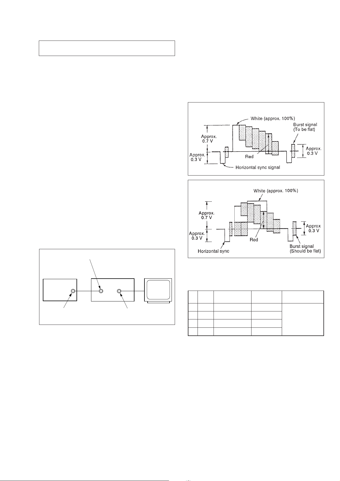
In this adjustment, PAL or NTSC pattern generator is connected
with LINE input signal terminal. When checking with tuner , connected AERIAL terminal. Check that the amplitudes of video signal SYNC signal, of picture portions, and of burst signals are flat
at approximately 0.3, 0.7 and 0.3 V, respectively, and that the level
ratio of the burst signal and “red” signal are 0.30: 0.66. Fig. 7-2-2.
shows video signals (color bars) used in adjusting the video section.
PAL
NTSC
2-1-2. Connection
Unless otherwise specified, connect and adjust the measuring instruments as shown in the following diagram.
VIDEO LINE IN
Pattern generator VCR
Video output
(75 Ω)
VIDEO LINE OUT
Monitor TV
Fig. 7-2-1
Fig. 7-2-2
2-1-4. Alignment T apes
[Alignment T ape (KRV -51N2/KR V-51P)]
Mode
1
SP
2
SP
3
EP
4
EP
2-1-5. Specified I/O Level and Impedance
Input/output terminal
Video inputs LINE IN : phono jack
Audio inputs LINE IN : phono jacks
Video outputs LINE OUT: phono jack
Audio outputs LINE OUT: phono jacks
Time
Seven minutes
Three minutes
Seven minutes
Three minutes
1 Vp-p, 75 Ω, unbalanced, sync negative
47 kW, –7.5 dBs (0 dBs = 0.775 Vrms)
More than 10 kW, –4 dBs
1 Vp-p, 75 Ω, unbalanced, sync negative
–7.5 dBs at load impedance 47 kΩ
Output impedance : less than 10 Ω
Video signal
Color bar
Monoscope
Color bar
Monoscope
(HiFi/Normal)
Audio signal
400 Hz
7-1
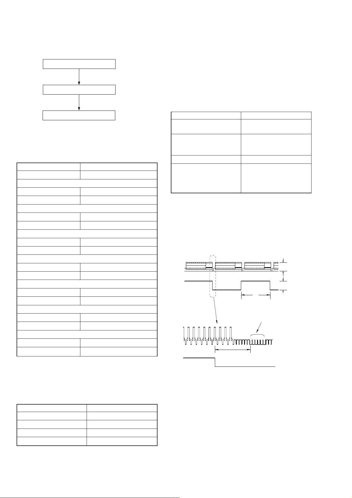
2-1-6. Adjusting Sequence
Make the electrical adjustment in the following sequence.
Power supply adjustment
Servo system adjustment
2-3. SERVO SYSTEM ADJUSTMENT
2-3-1. RF Switching Position Adjustment
(MA-400 BOARD)
Purpose:
Adjust the interval between A ch and B ch of tape playback output.
Improve the interchangeability with other tapes and sets.
When it is out of order, the interval appears on the screen, the
screen is disturbed.
Audio system adjustment
2-2. POWER SUPPLY ADJUSTMENTS
2-2-1. Power Supply Check
(SRV938EK BOARD)
Mode E-E
Measuring Instrument Digital voltmeter
MTR12 V check
Measurement Point Pin 5, 6 of CN201
Specified Value 13.5 ±0.4 V
D6 V check
Measurement Point Pin qf of CN201
Specified Value 5.9 ± 0.2 V
+13 V check
Measurement Point Pin qs of CN201
Specified Value 13.6 ± 0.5 V
+38 V check
Measurement Point Pin 2 of CN202
Specified Value 35.0 ± 3.5 V
SW 5 Vcheck
Measurement Point Pin qg, qh of CN201
Specified Value 5.2 ± 0.2 V
+F, –F check
Measurement Point Pin 4, 6 of CN202
Specified Value 2.9 V
–11 V check
Measurement Point Pin 3 of CN202
Specified Value –11.5 ± 1.0 V
+ 0.6
– 0.3
Mode PB
Signal Alignment tape SP mode
color bar
Measurement Point CH1: VIDEO LINE OUT
CH2: Pin 2 of CN262
(RF SWP)
Measuring Instrument Oscilloscope
Specified Value 6.5 ± 0.5 H (416 ± 32 µsec)
PAL
6.5 ± 0.5 H (410 ± 32 µsec)
NTSC
Adjusting Method:
1) During playback, connect MA-400 board CN262 pin 3 and
the pin 5 for about 1 second to activate the RF switching
position adjustment mode.
2) Check appear “A P” on FL display.
3) Using the channel + and – buttons, adjust to 6.5 ± 0.5 H.
4) Press the pause button.
CH1
CH2
CH1
CH2
V
enlargement
Vertical sync. signal
6.5 ± 0.5 H
(416 ± 32 µsec) PAL
(410 ± 32 µsec) NTSC
Approx. 1 Vp-p
Approx. 5 Vp-p
Checking Method:
1) Confirm that each voltage meets its specified value.
2-2-2. +6 V Adjustment
(SRV938EK BOARD)
Mode REC or PB
Measuring Instrument Digital voltmeter
Measurement Point Pin qf of CN201
Adjusting Element VR251
Specified Value 5.9 ± 0.2 V
Fig. 7-2-3.
7-2
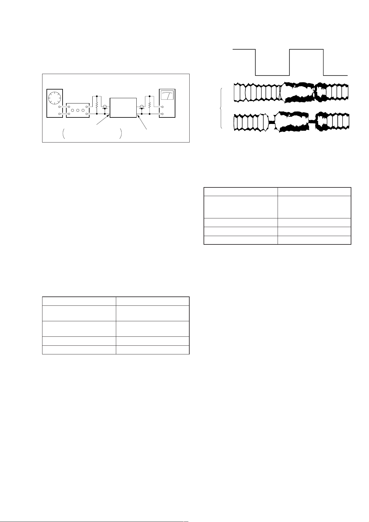
2-4. AUDIO SYSTEM ADJUSTMENTS
• Adjust both Lch and Rch.
[Connection]
CH1
RF SWP
Audio
generator
600 Ω
Attenuator
AUDIO LINE IN
Feed signal both
channelssimultaneously.
Audio level meter or
distortion meter
47 kΩ
VCR
AUDIO LINE OUT
Fig. 7-2-4.
2-4-1. Hi-Fi Audio System Adjustment
• Set switches and knobs to the following positions to make adjustment unless otherwise specified.
INPUT SELECT switch................... LINE
AUDIO MONITOR .......................... STEREO
[Adjustment Sequence]
1. AF Switching Position Adjustment
2. Frequency Response Check
3. Overall Level Characteristic and Distortion Factor
Check
4. Overall S/N Check
1. AF Switching Position Adjustment
(MA-400 BOARD)
Purpose:
Adjust the interval between A CH and B CH of tape playback
output. Improve the interchangeability with other tapes and sets.
When it is out of order, noisy sound is increased and big noise is
heard.
Mode PB
Signal Alignment tape SP mode
color bar
Measurement point CH1: Pin 2 of CN262
CH2: Pin 1 of CN262
Measuring Instrument Oscilloscope
Specified Value Fig. 7-2-5
OK
CH2
NG
Fig. 7-2-5.
2. Frequency Response Check
Purpose:
Confirm that the frequency characteristic is within the specification.
Mode REC and PB (SP, LP mode)
Signal 400 Hz, –26.3 dBs
30 Hz, –26.3 dBs
20 kHz, –26.3 dBs
Measurement point Audio output terminal
Measurement equipment Audio level meter
Specified value 0 ± 3 dB
Note: Tape path adjustment must have been completed.
Confirmation Method:
1) Supply a signal of 400 Hz, –26.3 dBs to both L and R channels of Audio Line Input.
2) Connect the audio level meter to the Audio Line Output.
3) Adjust the attenuator so that the audio level meter will indicate –26.3 dBs.
4) Make recording.
5) Set an audio line input signal to 30 Hz and make recording.
6) Set an audio line input signal to 20 kHz and make recording.
7) Playback a recorded portion, and measure output levels at 400
Hz and 30 Hz and 20 kHz.
8) Confirm that the 30 Hz and 20 kHz playback output level within
a range of the 400 Hz playback output level 0 ± 3 dB.
Adjusting Method:
1) During playback, connect MA-400 board CN262 pin 3 and
the pin 5 for about 1 second to activate the RF switching
position adjustment mode.
2) Press the record button to activate the AF switching position
adjustment mode.
3) Check appear “A H” on FL display.
4) Using the channels + and – buttons, minimize a chipped portion. At this time, confirm that a noisy sound is not heard.
5) Press the pause button.
7-3
 Loading...