

Sony SLV-SE310G-I User Manual
3-065-672-11 (1) GB
Video Cassette
Recorder
Operating Instructions
PAL
SLV-SE310G/I
© 2001 Sony Corporation

WARNING
To prevent fire or shock hazard, do not expose the
unit to rain or moisture.
Toavoid electrical shock, do not open the cabinet.
Refer servicing to qualified personnel only.
Mains lead must only be changed at a qualified
service shop.
Notice for customers in the United
Kingdom and Republic of Ireland
A moulded plugcomplying with BS1363 is fitted to
this equipment for your safety and convenience.
If the 13A fitted plug does not match the outlet
socket in your home, please refer to your Appointed
Sony Dealer for advice.
Should the fuse in the plug supplied need to be
replaced, a 5 AMP fuse approvedby ASTAor BSI
to BS1362, (i.e., marked with or mark)
must be used.
If the plug supplied with this equipment has a
detachable fuse cover, be sure to attach the fuse
coverafter you change the fuse. Never use the plug
without the fuse cover. If you should lose the fuse
cover, please contact your nearest Sony service
station.
Precautions
Safety
• This unit operates on 220 – 240 V AC, 50 Hz.
Check that the unit’s operating voltage is
identical with your local power supply.
• If anything falls into the cabinet, unplug the unit
and have it checked by qualified personnel before
operating it any further.
• The unit is not disconnected from the mains as
long as it is connected to the mains, even if the
unit itself has been turned off.
• Unplug the unit from the wall outlet if you do not
intend to use it for an extended periodof time. To
disconnect the cord, pull it out by the plug, never
by the cord.
Installing
• Allow adequate air circulation to prevent internal
heat buildup.
• Do not place the unit on surfaces (rugs, blankets,
etc.) or near materials (curtains, draperies) that
may block the ventilation slots.
• Do not install the unit near heat sources such as
radiators or air ducts, or in a place subject to
direct sunlight, excessive dust, mechanical
vibration or shock.
• Do not install the unit in an inclined position. It is
designed to be operated in a horizontal position
only.
• Keep the unit and cassettes away from equipment
with strong magnets, such as microwave ovens or
large loudspeakers.
• Do not place heavy objects on the unit.
• If the unit is brought directly from a cold to a
warm location, moisture may condense inside the
VCR and cause damage to the video head and
tape. When you first install the unit, or when you
move it from a cold to a warm location, wait for
about three hours before operating the unit.
Caution
Televisionprogrammes, films,video tapes and other
materials may be copyrighted. Unauthorized
recording of such materialm ay be contrary to the
provisions of the copyright laws. Also, use of this
recorder with cable television transmission may
require authorization from the cable television
transmitter and/or programme owner.
Compatible colour systems
This VCR is designed to record and play back using
the PAL colour system. Recording of video sources
based on other colour systems cannot be guaranteed.
VIDEO Plus+ and PlusCode are registered
trademarksof Gemstar DevelopmentCorporation.
The VIDEO Plus+ system is manufactured under
license from Gemstar Development Corporation.
WARNING
2

Table of contents
Getting Started
Getting Started
4 Index to parts and controls
9 Step 1 : Unpacking
10 Step 2 : Setting up the remote
commander
13 Step 3 : Connecting the VCR
17 Step4:SettinguptheVCRwith
the Auto Set Up function
19 Step 5 : Tuning your TV to the
VCR
21 Selecting a language
22 Presetting channels
25 Changing/disabling programme
positions
30 Setting the clock
34 Setting your personal code
Basic Operations
36 Playing a tape
38 Recording TV programmes
41 Recording TV programmes using
the Dial Timer
46 Recording TV programmes using
the VIDEO Plus+ system
50 Setting the timer manually
67 Editing with another VCR
Additional Information
69 Troubleshooting
73 Specifications
74 Index
Back Cover
Quick Start Guide
Additional Operations
53 Playing/searching at various speeds
54 Setting the recording duration time
55 Synchronized Recording
57 Checking/changing/cancelling
timer settings
59 Searching using the Smart Search
function
62 Adjusting the picture
64 Reducing the VCR’s power
consumption
65 Changing menu options
Table of contents
3
Getting Started
Index to parts and controls
Refer to the pages indicated in parentheses ( ) for details.
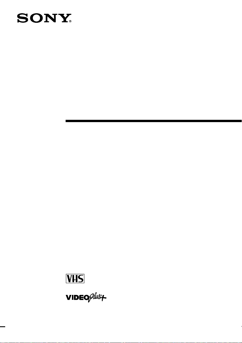
Front panel
A?/1 (on/standby) switch (34)
BA (eject) button (36)
CTape compartment
DRemote sensor (10)
Em (rewind) button (36) (53)
FH (play) button (36) (53)
GM (fast-forward) button (36) (53)
Hz REC(record)button(38)(54)(68)
Ix (stop) button (36) (68)
JX (pause) button (36) (68)
K DIAL TIMER (41)
LSYNCHRO REC (Synchronized
Recording) button (56)
MPROGRAM +/– buttons (20) (53)
(62)
NAUTO SET UP/
RF (Radio Frequency) CHANNEL
button (17) (19)
Index to parts and controls
4
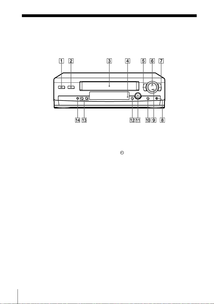
Display window
Getting Started
SP
LP
EP
ATimer indicator (43) (47) (51)
BTape speed indicators (38)
CVIDEO indicator (14) (39)
DVPS (Video Programme System)/
PDC (Programme Delivery Control)
indicator (48)
EOPC (Optimum Picture Control)
indicator (62)
SMARTLINKVIDEO VPS
PDC OPC
TV
FSMARTLINK indicator (15)
GTV indicator (40)
HTracking i ndicator (62)
ITime counter/clock/line/programme
position indicator (36) (38) (68)
JRemaining time indicator (39)
KTape/recording indicator (38)
continued
Index to parts and controls
5
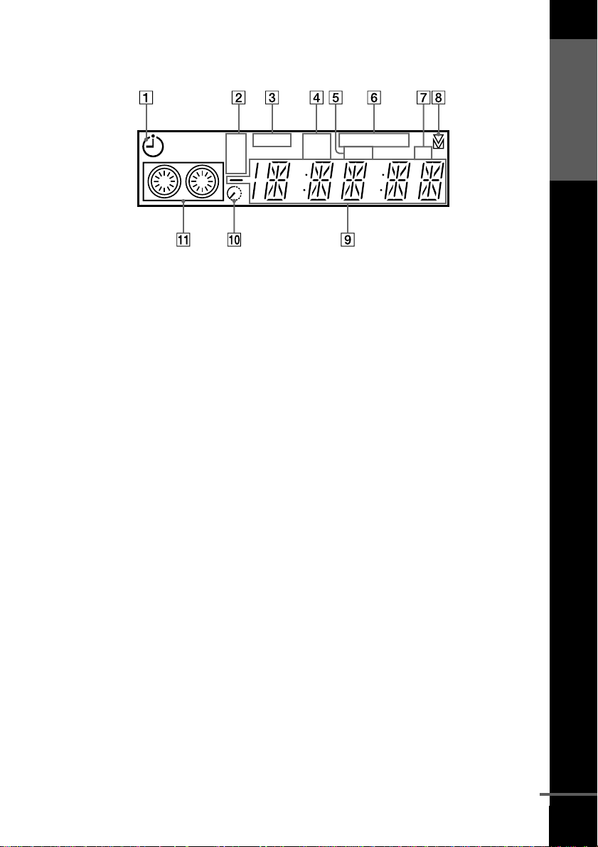
Rear panel
AMains lead (13) (14)
BAERIAL IN
ANTENNE ENTREE connector (13)
(14)
CAERIAL OUT
ANTENNE SORTIE connector (13)
(14)
Dt LINE-2 IN
t ENTREE LIGNE-2 connector
(16) (55) (67)
Ei LINE-1 (TV)
i LIGNE-1 (TV) connector (14)
Index to parts and controls
6
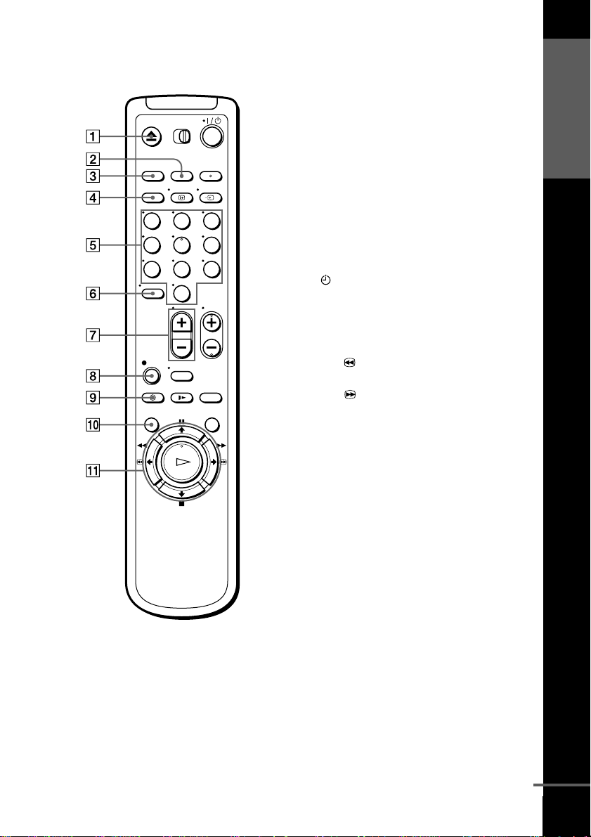
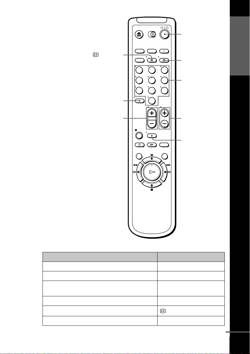
Remote commander
AZ EJECT button (36)
BCOUNTER/REMAIN button (39)
CCLEAR button (36) (46) (57)
DSP (Standard Play)/LP (Long Play)
button (38)
EProgramme number buttons (11) (39)
F- (ten’s digit) button (11) (39)
Getting Started
123
456
789
0
G2 (volume) +/– buttons (for TV)
(11)
Hz REC (record) button (38) (54)
I TIMER button (46) (50)
JMENU button (30) (57)
KX PAUSE/M button (30) (36)
x STOP/m button (30) (36)
m REW (rewind)/< button
(36) (53)
M FF (fast-forward)/, button
(36) (53)
H PLAY/OK button (30) (36)
continued
Index to parts and controls
7
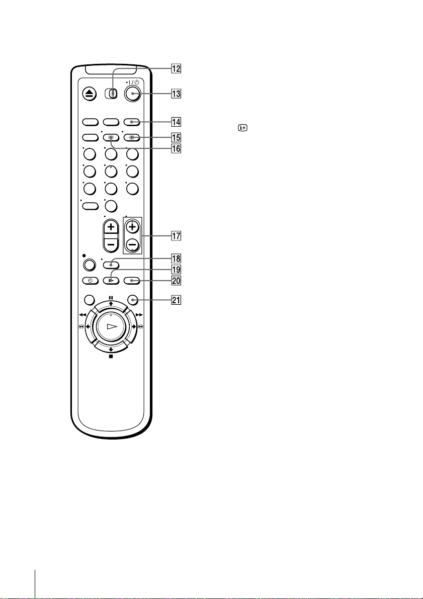
L[TV] / [VIDEO] remote control switch
(10)
M?/1 (on/standby) switch (11) (47)
NINPUT SELECT button (39) (51)
(68)
Ot TV/VIDEO button (11) (14) (39)
P DISPLAY button (39)
123
456
789
0
QPROG (programme) +/– buttons (11)
(23) (38)
RWIDE button (for TV)(11)
Sy SLOW button (53)
T×2 button (53)
USMART SEARCH button (59)
Index to parts and controls
8
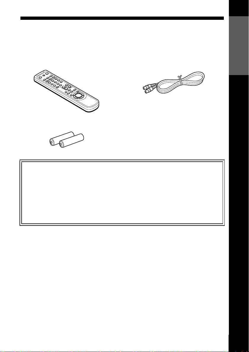
Step 1 : Unpacking
Check that you have received the following items with the VCR:
• Remote commander • Aerial cable
• R6 (size AA) batteries
Check your model name
The instructions in this manual are for the 2 models: SLV-SE310G and SE310I.
Check your model number by looking at the rear panel of your VCR.
SLV-SE310G is the model used for illustration purposes. Any difference in
operation is clearly indicated in the text, for example, “SLV-SE310I only.”
Getting Started
Unpacking
9
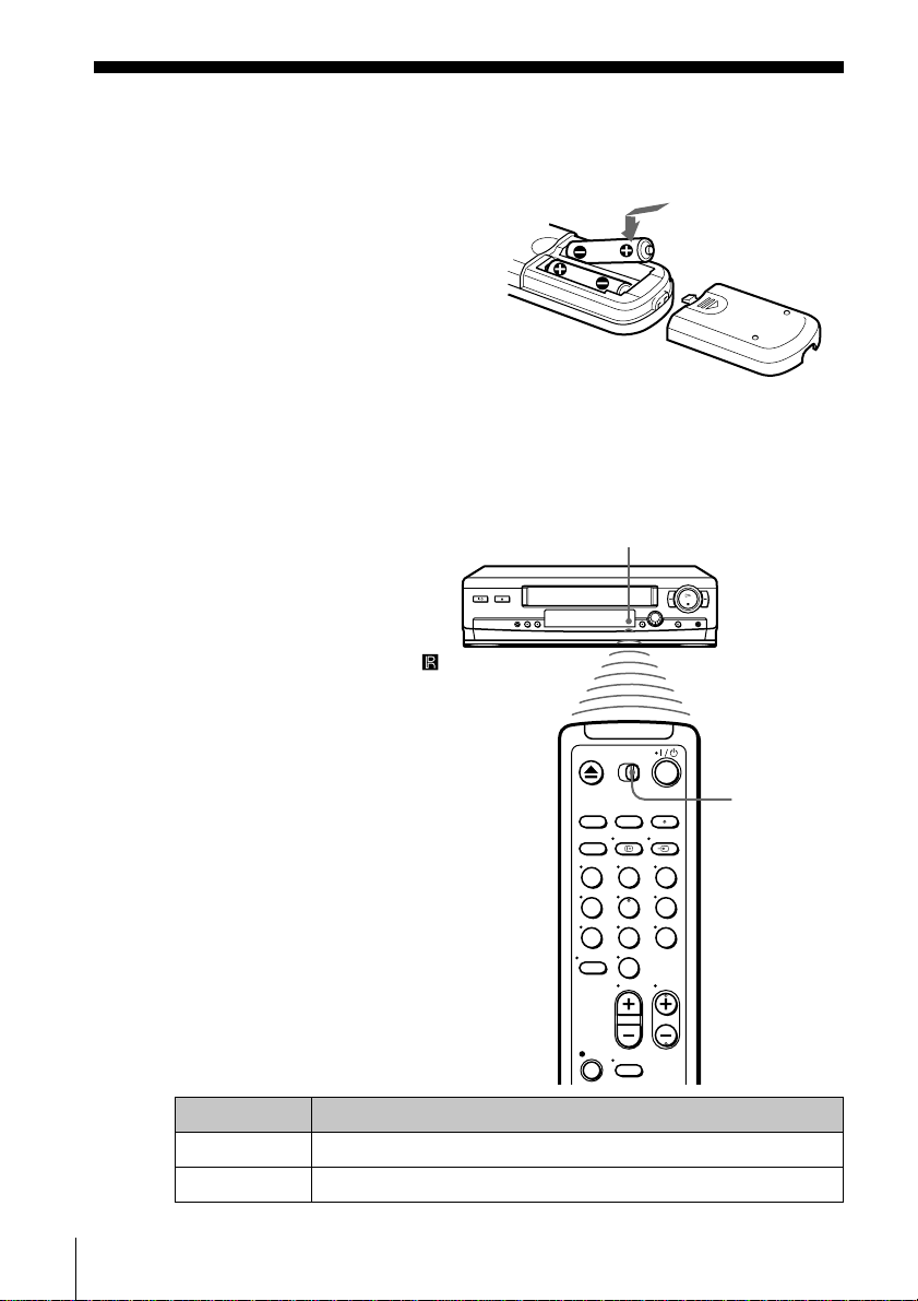
Step 2 : Setting up the remote commander
Inserting the batteries
Insert two R6 (size AA)
batteries by matchingthe + and
– on the batteries to the
diagram inside the battery
compartment.
Insert the negative (–) end first,
then push in and down until the
positive (+) end clicks into
position.
Using the remote commander
You can use this remote
commander to operate this
VCR and a Sony TV. Buttons
on the remote commander
marked with a dot (•) can be
used to operate your Sony TV.
If the TV does not have the
symbol near the remote sensor,
this remote commander will
not operate the TV.
Remote sensor
To operate Set [TV] / [VIDEO] to
the VCR [VIDEO] and point at the remote sensor at the VCR
aSonyTV [TV] and point at the remote sensor at the TV
Setting up the remote commander
10
[TV] /
[VIDEO]
123
456
789
0
?/1
Getting Started
DISPLAY
-
2 +/–
123
456
789
0
t TV/VIDEO
Programme
number buttons
PROG +/–
WIDE
TV control buttons
To Press
Set the TV to standby mode ?/1
Select an input source: aerial in or line in t TV/VIDEO
Select the TV’s programme position Programme number buttons,
-,PROG+/–
Adjust the volume of the TV 2 +/–
Call up the on-screen display
Switch to/from wide mode of a Sony wide TV WIDE
DISPLAY
continued
Setting up the remote commander
11

Notes
• With normal use, the batteries should last about three to six months.
• If you do not use the remote commander for an extendedperiod of time, remove
the batteries to avoid possible damage from battery leakage.
• Do not use a new battery together with an old one.
• Do not use different types of batteries together.
• Some buttons may not work with certain SonyTVs.
Setting up the remote commander
12
Step 3 : Connecting the VCR
If your TV has a Scart (EURO-AV) connector, see page 14.
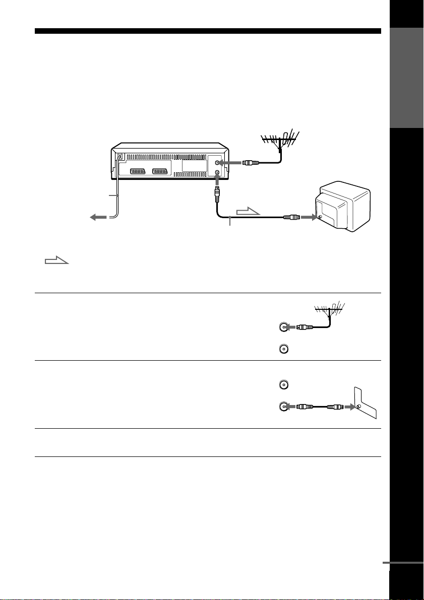
If your TV does not have a Scart (EURO-AV) connector
AERIAL IN
AERIAL OUT
Mains lead
to mains
Aerial cable (su pplied)
: Signal flow
Getting Started
AERIAL IN
1
2
3
Disconnect the aerial cable from
your TV and connect it to
AERIAL IN on the rear panel of
the VCR.
Connect AERIAL OUT of the
VCR and the aerial input of your
TV using the supplied aerial cable.
AERIAL
ANTENNE
AERIAL
ANTENNE
IN
ENTREE
OUT
SORTIE
IN
ENTREE
OUT
SORTIE
Connect the mains lead to the mains.
Note
• When you connect the VCR and your TV only with an aerial cable, you have to
tune your TV to the VCR (see page 19).
continued
Connecting the VCR
13
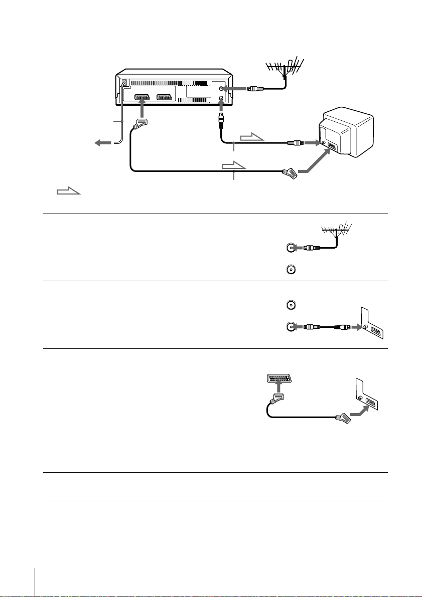
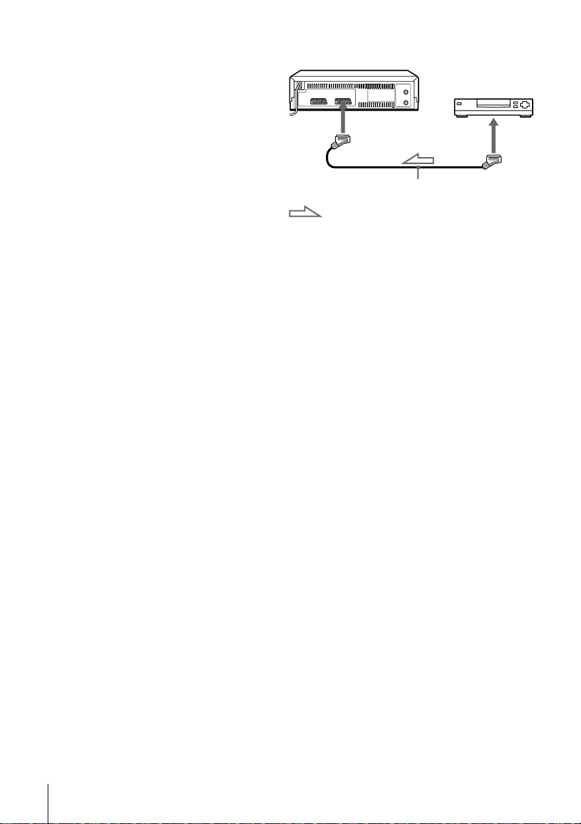
If your TV has a Scart (EURO-AV) connector
AERIAL IN
1
2
3
Mains lead
to mains
: Signal flow
i LINE-1
(TV)
Aerial cable (supplied)
Scart cable (not supplied)
AERIAL OUT
Disconnect the aerial cable from
your TV and connect it to
AERIAL IN on the rear panel of
the VCR.
Connect AERIAL OUT of the
VCR and the aerial input of your
TV using the supplied aerial cable.
ConnectLINE-1 (TV) onthe VCR
and the Scart (EURO-AV)
connector on the TV with the
optional Scart cable.
This connection improves picture
and sound quality. Whenever you
want to watch the VCR picture,
press t TV/VIDEO to display
the VIDEO indicator in the
display window.
AERIAL IN
IN
ENTREE
AERIAL
ANTENNE
OUT
SORTIE
IN
ENTREE
AERIAL
ANTENNE
OUT
SORTIE
Scart (EURO-AV)
4
Connecting the VCR
14
Connect the mains lead to the mains.
Note
• If the TV is connected to the LINE-1 (TV) connector, setting the RF channel to
OFF is recommended. In the OFF position, only the signal from the aerial is
output through the AERIAL OUT connector (see page 20).
About the SMARTLINK features
If the connected TV complies
with SMARTLINK,
MEGALOGIC*
Q-Link*
3
or T-V LINK*
automatically runs the SMARTLINK function after you complete the steps
on the previous page (the SMARTLINK indicator appears in the VCR’s
display window when you turn on the TV). You can enjoy the following
SMARTLINK features.
• Preset Download
You can download your TV tuner preset data to this VCR and tune the
VCR according to that data in Auto S et Up. This greatly simplifies the
Auto Set Up procedure. Be careful not to disconnect the cables or exit the
Auto Set Up function during the procedure.
See “Setting up the VCR with the Auto Set Up function” on page 17.
• TV Direct Rec
You can easily record what you are watching on the TV. For details, see
“Recording what you are watching on the TV (TV Direct Rec)” on page
40.
•OneTouchPlay
With One Touch Play, you can start playback automatically without
turning on the TV. For details, see “Starting playback automatically with
one button (One Touch Play)” on page 37.
•OneTouchMenu
You can turn on the VCR and TV, set the TV to the video channel, and
display the VCR’s on-screen display automatically by pressing MENU on
theremotecommander.
•OneTouchTimer
You can turn on the VCR and TV, set the TV to the video channel, and
display the timer recording menu (the TIMER METHOD menu, the
TIMER menu, or the VIDEO Plus+ menu) automatically by pressing
TIMER on the remote commander.
You can set which timer recording menu is displayed using TIMER
OPTIONS in the OPTIONS-2 menu (see page 66).
• Automatic Power Off
You can have the VCR turn off automatically, if the VCR is not used after
you turn off the TV.
1
, EASYLINK*2,
, EURO VIEW LINK*4,
5
,thisVCR
SMARTLINK
Getting Started
*1“MEGALOGIC” is a registered trademark of Grundig Corporation.
*2“EASYLINK” is a trademark of Philips Corporation.
3
“Q-Link” is a trademark of Panasonic Corporation.
*
*4“EURO VIEW LINK” is a trademark of Toshiba Corporation.
5
“T-V LINK” is a trademark of JVC Corporation.
*
Note
• Not all TVs respond to the functions above.
Connecting the VCR
continued
15
Additional connection
To aset top box with Line
Through
Using the Line Through
function, you can watch
programmes from a set top
box connected to this VCR on
theTVevenwhentheVCRis
turned off. When you turn on
the set top box, this VCR
automatically sends the signal
from the set top boxto the TV
without turning itself on.
Connect the set top box to the LINE-2 IN connector as shown above.
1
Set POWER SAVE to OFF in the OPTIONS-2 menu.
2
Turn off the VCR.
3
To watch a programme, turn on the set top box and the TV.
Note
• You cannot watch programmes on the TV while recording unless you are recording
a programme from your set top box.
tLINE-2 IN
Scart cable (not supplied)
: Signal flow
LINE OUT
Connecting the VCR
16
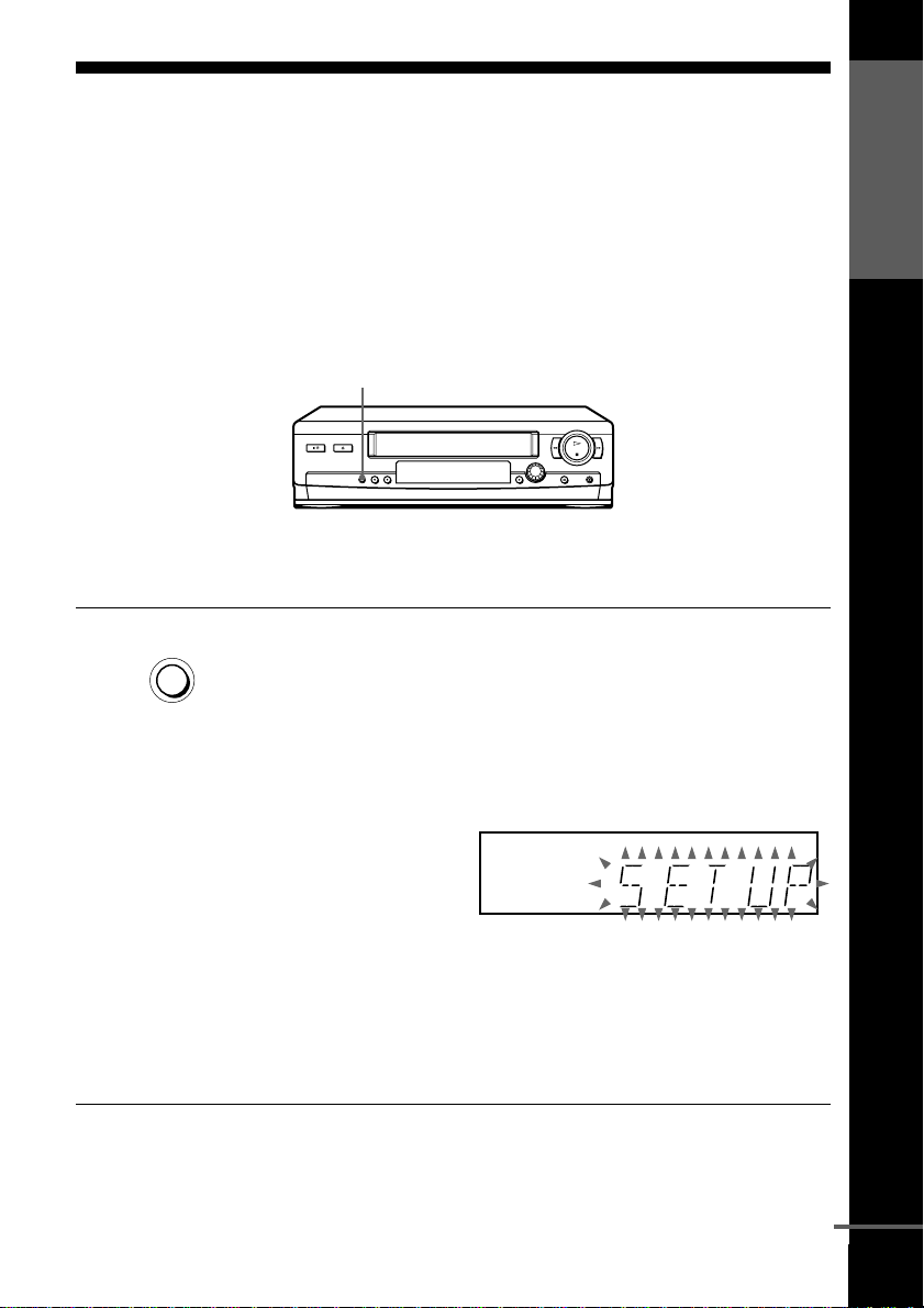
Step4:SettinguptheVCRwiththeAuto
Set Up function
Before using the VCR for the first time, set up the VCR using the Auto Set
Up function. With this function, you can set the TV channels, guide
channels for the VIDEO Plus+ system, R F channel, and VCR clock
automatically.
AUTO SET UP
Getting Started
AUTO SET UP
RF CHANNEL
Hold down AUTO SET UP on the VCR for more than three
seconds.
The VCR automatically turns on, and starts searching for all of the
receivable channels and presets them in the appropriate order for
your local area.
If you want to change the order of the channels or disable unwanted
programme positions, see “Changing/disabling programme
positions” on page 25.
If you use the SMARTLINK connection, the Preset Download
function starts and the SMARTLINKindicator flashes in the display
window during download.
After the search or download is complete, the current time appears
in the display window for any stations that transmit a time signal.
If the time does not appear, set the clock manually, see page 30.
continued
Setting up the VCR with the Auto Set Up function
17

To cancel the Auto Set Up function
Press AUTO SET UP.
Notes
• IfyoustoptheAutoSetUpfunctionduringstep3,youmustrepeatsetupfrom
step 1.
• Whenever you operate the Auto Set Up function, some of the settings (VIDEO
Plus+, timer, etc.) will be reset. If this happens, you have to set them again.
Setting up the VCR with the Auto Set Up function
18
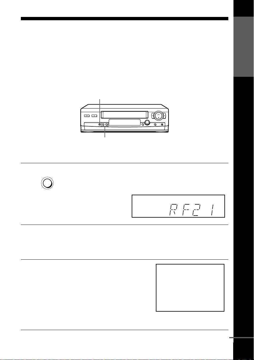
Step 5 : Tuning your TV to the VCR
If your TV has a Scart (EURO-AV) connector, see page 20.
If your TV does not have a Scart (EURO-AV) connector
Follow the steps below so that your TV will properly receive the video
signals from your VCR.
RF CHANNEL
PROGRAM +/–
Getting Started
1
2
3
AUTO SET UP
RF CHANNEL
Press RF CHANNEL on the VCR lightly.
The factory-preset RF channel appears in the display window.
The VCR signal is output through this channel to the TV.
Turn on your TV and select a programme position for the VCR
picture.
This programme position will now be referred to as the video
channel.
Tune the TV to the same channel
shown in the VCR display window
so that the picture on the right
appears clearly on the TV screen.
RefertoyourTVmanualforTV
tuning instructions.
If the picture does not appear
clearly, see “To obtain a clear
picture from the VCR” below.
SONY VIDEO CASSETTE RECORDER
continued
Tuning your TV to the VCR
19
4
AUTO SET UP
Press RF CHANNEL.
You have now tuned your TV to the VCR. Whenever you want to
play a tape, set the TV to the video channel.
RF CHANNEL
TochecktoseeiftheTVtuningiscorrect
Set the TV to the video channel and press PROGRAM +/– on the VCR. If
the TV screen changes to a different programme each time you press
PROGRAM +/–, the TV tuning is correct.
To obtain a clear picture from the VCR
If the screen does not appear clearly in step 3 above, press PROGRAM +/–
so that another RF channel appears. Then tune the TV to the new RF
channel so that a clear picture appears.
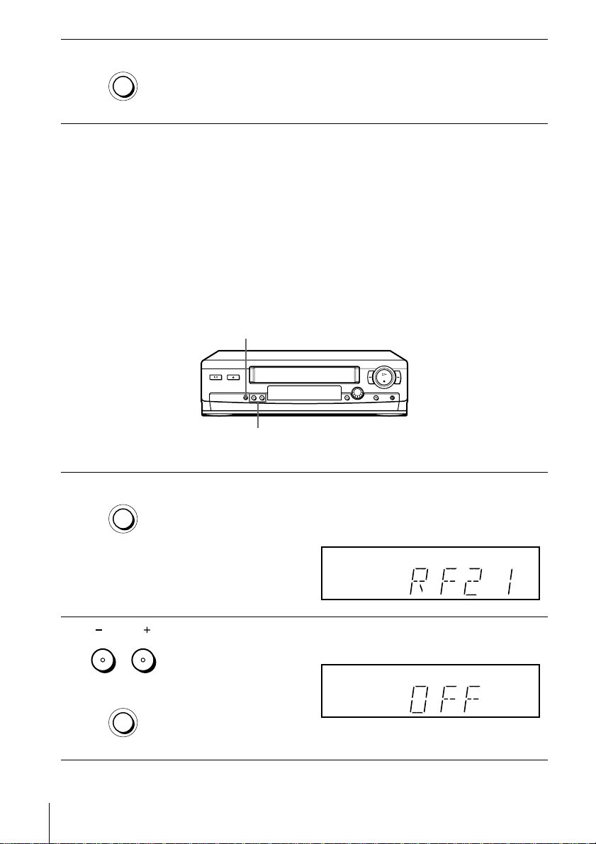
If your TV has a Scart (EURO-AV) connector
RF CHANNEL
PROGRAM +/–
AUTO SET UP
1
RF CHANNEL
2
Tuning your TV to the VCR
20
PROGRAM
AUTO SET UP
RF CHANNEL
Press RF CHANNEL on the VCR lightly.
The factory-preset RF channel appears in the display window.
The VCR signal is output through this channel to the TV.
Press PROGRAM +/– to set the RF channel to OFF, and p ress RF
CHANNEL again.
RF channel set up is complete.
Selecting a language
If you prefer an on-screen language other than English, use the on-screen display to
select another language.
Before you start…
• TurnontheVCRandtheTV.
• Set the TV to the video channel.
• Refer to “Index to parts and controls” for button locations.
Getting Started
1
2
3
4
MENU
PLAY
OK
PLAY
OK
PLAY
OK
MENU
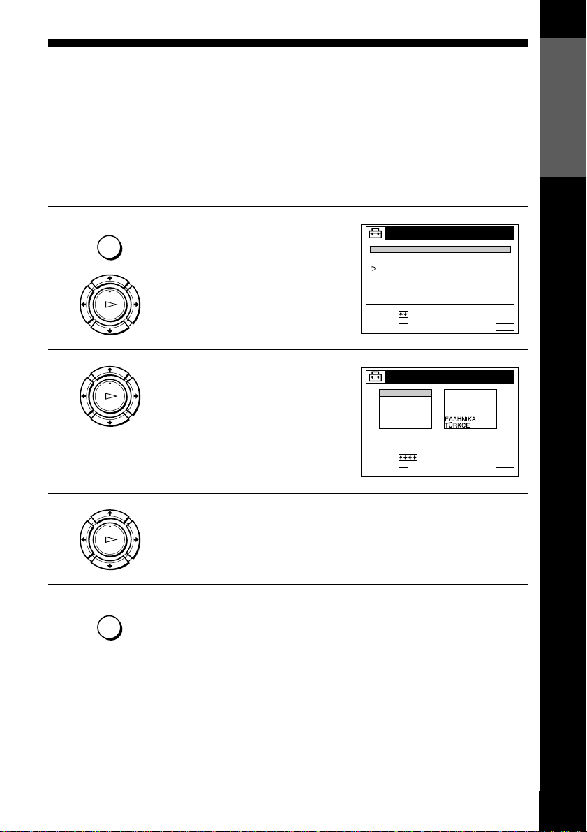
Press MENU, then press M/m to
highlight SETTINGS and press OK.
Press M/m to highlight
LANGUAGE, then press OK.
TUNER
CLOCK
LANGUAGE
RETURN
SELECT :
SET :
ENGLISH
DEUTSCH
FRANÇAIS
ITALIANO
ESPAÑOL
PORTUGUÊS
SELECT :
SET :
SETTINGS
OK
LANGUAGE
OK
NEDERLANDS
DANSK / NORSK
SVENSKA
SUOMI
MENUEXIT :
MENUEXIT :
Press M/m/</, to highlight the desired language, then press OK.
Press MENU to exit the menu.
Tip
• If you want to return to the previous menu, highlight RETURN and p ress OK.
Note
• The menu disappears automatically if you don’t proceed for more than a few
minutes.
Selecting a language
21
Presetting channels
If some channels could n ot be preset using the Auto Set Up function, you can preset
them manually.
Before you start…
• Turn on the VCR and the TV.
• Set the TV to the video channel.
• Refer to “Indexto parts and controls” for button locations.
1
2
3
MENU
PLAY
OK
PLAY
OK
PLAY
OK
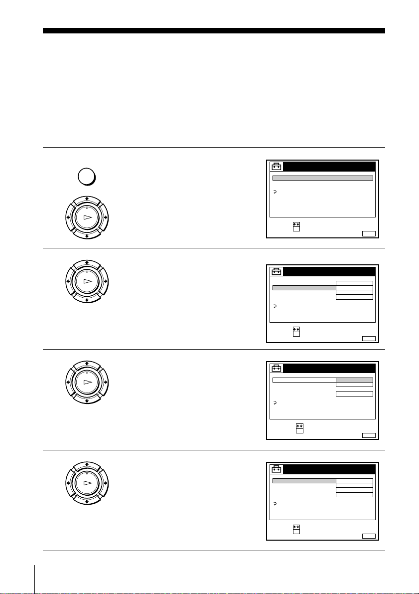
Press MENU, then press M/m to
highlight SETTINGS and press OK.
Press M/m to highlight TUNER,
then press OK.
SLV-SE310I only:
Press M/m to highlight NORMAL/
CATV, then press OK.
SETTINGS
TUNER
CLOCK
LANGUAGE
RETURN
SELECT :
SET :
OK
ex. SLV-SE310I
TUNER
NORMAL / CATV
CHANNEL SET
PAY - TV / CANAL+
AFT
FINE TUNING
RETURN
SELECT :
SET :
OK
TUNER
NORMAL / CATV
CHANNEL SET
PAY - TV / CANAL+
AFT
FINE TUNING
RETURN
SELECT :
CONFIRM :
OK
NORMAL
C
OFF
ON
NORMAL
CATV
ON
MENUEXIT :
PROG. 1
AAB12
MENUEXIT :
PROG.
MENUEXIT :
1
4
Presetting channels
22
PLAY
OK
SLV-SE310I only:
Press M/m to highlight NORMAL,
then press OK.
To preset CATV (Cable Television)
channels, select CATV.
TUNER
NORMAL / CATV
CHANNEL SET
PAY - TV / CANAL+
AFT
FINE TUNING
RETURN
SELECT :
SET :
OK
NORMAL
C
OFF
ON
PROG. 1
AAB12
MENUEXIT :
5
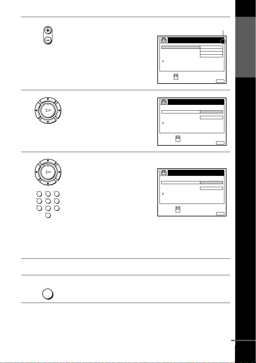
• PROG
Press PROG +/– to select the
programme position.
TUNER
NORMAL / CATV
CHANNEL SET
PAY - TV / CANAL+
AFT
FINE TUNING
RETURN
SELECT :
SET :
OK
Selectedprogramme
position
PROG. 4
NORMAL
C
AAB12
OFF
ON
MENUEXIT :
Getting Started
6
7
8
PLAY
OK
PLAY
OK
123
456
789
0
Press M/m to highlight CHANNEL
SET, then press OK.
TUNER
NORMAL / CATV
CHANNEL SET
PAY - TV / CANAL+
AFT
FINE TUNING
RETURN
SELECT :
CONFIRM :
OK
PROG.
4
C
AAB12
ON
MENUEXIT :
Press M/m repeatedly until the channel you want is displayed.
The channels appear in the
following order:
• VHF IA - IJ, SA10 - SA13
(SLV-SE310I only)
• UHF B21 - B69
• CATVS1-S20(SLV-SE310I
only)
TUNER
NORMAL / CATV
CHANNEL SET
PAY - TV / CANAL+
AFT
FINE TUNING
RETURN
SELECT :
CONFIRM :
OK
PROG.
4
C
27
ON
MENUEXIT :
• HYPER S21 - S41 (SLV-SE310I
only)
• CATV S01 - S05 (SLV-SE310I only)
If you know the number of the channel you want, press the
programme number buttons. For example, for channel 5, first press
“0” and then press “5.”
To preset another programme position, repeat steps 5 through 7.
9
MENU
Press MENU to exit the menu.
continued
Presetting channels
23
 Loading...