

Sony SLV-CA30,SLV-GA35,SLV-GA55,SLV-SP70,SLV-SA33,SLV-SP100,SLV-GA65,SLV-GF85 Service Manual
MICROFILM
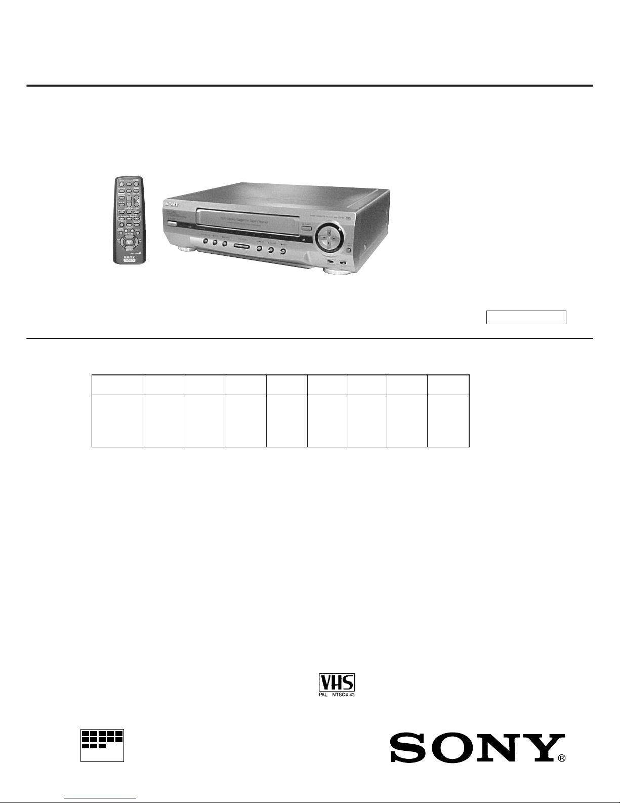
SERVICE MANUAL
GA35ME
GA35PL
GA35PS
GA35SG
GA35TH
GA35TW
All model
names
SLV-
GF85PL
GF85PS
GF85TH
GF85TW
GA55ME
GA55PL
GA55PS
GA55SG
GA55TH
GA65MJ
SP70R SP100R
E Model
SLV-GA35PS/GA55PS/GF85PS
ME Model
SLV-GA35ME/GA35SG/GA55ME/GA55SG
Middle East Model
SLV-GA65MJ
Philippine Model
SLV-GA35PL/GA55PL/GF85PL
Russian Model
SLV-SP70R/SP100R
Taiwan Model
SLV-CA30TW/GA35TW/GF85TW/SA33TW
Thailand Model
SLV-GA35TH/GA55TH/GF85TH
VIDEO CASSETTE RECORDER
• Refer to the SERVICE MANUAL of VHS MECHANICAL
ADJUSTMENTS VI for MECHANICAL ADJUSTMENTS.
(9-921-647-11)
* The abbreviations of CA30, GA35, GA55, GA65, GF85, SA33, SP70 and SP100 contained in this service
manual are indicated when these models are common to all their corresponding models as given below.
GA35
Abbreviated
model name
GA55 GA65 GF85
RMT-V286/V286A/V286B/V286C
SLV-CA30/GA35/GA55/GA65
/
GF85/SA33/SP70/SP100
Photo: SLV-GF85
SP70 SP100
SPECIFICATIONS
– Continued on next page –
S MECHANISM
CA30TW
CA30
SA33TW
SA33
System
EXCEPT CA30/GA35: PL, TW/GA55PL/
GF85: PL, TW/SA33:
Color system
PAL, MESECAM, NTSC 3.58, NTSC 4.43
RF output signal
UHF channel 30 to 90
(B/G, D/K)
Aerial out
75-ohm asymmetrical aerial socket
CA30/GA35: PL, TW/GA55PL/GF85: PL, TW/
SA33:
Format
VHS NTSC standard
Video recording system
Rotary head helical scanning FM system
Video heads
Double azimuth two heads
Video signal
NTSC color, EIA standards
Maximum recording/playback time
9 hrs. in EP mode (with T-180 tape)
Fast-forward and rewind time
Approx. 4 min. 30 sec. (with T-120 tape)
Tape speed (GA55/GA65/GF85: PL, TW/SP70)
SP: 33.35 mm/s
EP: 11.11 mm/s
LP: 16.67 mm/s, playback only
Tuner section: CA30/GA35: PL, TW/GA55PL/
GF85: PL, TW/SA33
RF output channel
VHF channel 3 or 4
Antenna
75-ohm antenna terminal for VHF/UHF
Inputs and outputs
LINE 1 IN (EXCEPT CA30/GA35/SA33)
VIDEO IN, phono jack (1)
Input signal: 1 Vp-p, 75 ohms,
unbalanced, sync negative
AUDIO IN (MONO), phono jack (1)
(GA55/GA65/SP70)
AUDIO IN, phono jack (2) (GF85/SP100)
Input level: 327 m Vrms
Input impedance: more than 47 kilohms
– 2 –
SAFETY CHECK-OUT
1. Check the area of your repair for unsoldered or poorly-soldered connections. Check the entire board surface for solder
splashes and bridges.
2. Check the interboard wiring to ensure that no wires are
“pinched” or contact high-wattage resistors.
3. Look for unauthorized replacement parts, particularly transistors, that were installed during a previous repair. Point them
out to the customer and recommend their replacement.
After correcting the original service problem, perform the following
safety checks before releasing the set to the customer:
4. Look for parts which, though functioning, show obvious signs
of deterioration. Point them out to the customer and recommend their replacement.
5. Check the B+ voltage to see it is at the values specified.
SAFETY-RELATED COMPONENT WARNING!!
COMPONENTS IDENTIFIED BY MARK 0 OR DOTTED
LINE WITH MARK 0 ON THE SCHEMATIC DIAGRAMS
AND IN THE PARTS LIST ARE CRITICAL TO SAFE
OPERATION. REPLACE THESE COMPONENTS WITH
SONY PARTS WHOSE PART NUMBERS APPEAR AS
SHOWN IN THIS MANUAL OR IN SUPPLEMENTS PUBLISHED BY SONY.
LINE 1 OUT
VIDEO OUT, phono jack (1)
Output signal: 1 Vp-p, 75 ohms,
unbalanced, sync negative
AUDIO OUT (MONO), phono jack (1)
(EXCEPT GF85/SP100)
AUDIO OUT, phono jack (2)
(GF85/SP100)
Standard output: 327 mVrms
Load impedance: 47 kilohms
Output impedance: less than 10 kilohms
General
Power requirements
110 – 240 V AC, 50/60 Hz
(EXCEPT CA30/GA35TW/GF85TW/SA33)
110 V AC, 60 Hz
(CA30/GA35TW/GF85TW/SA33)
Power consumption
10 W (CA30/GA35: PL, TW/GA55PL/
GF85: PL, TW/SA33)
12 W
(EXCEPT CA30/GA35: PL, TW/GA55PL/
GF85: PL, TW/SA33)
Operating temperature
5 °C to 40 °C
Storage temperature
–20 °C to 60 °C
Dimensions
Approx. 355 × 96 × 293 mm (w/h/d)
Including projecting parts and controls
Mass
Approx. 3.8 kg
Supplied accessories
Remote commander (1)
R6 (Size AA) batteries (2)
Aerial cable (1)
(EXCEPT CA30/GA35: PL, TW/GA55PL/
GF85: PL, TW/SA33)
Audio /video cable (3-phono to 3- phono) (1)
(GF85/SP100)
75-ohm coaxial cable with F type connectors (1)
(CA30/GA35: PL, TW/GA55PL/GF85: PL,TW/
SA33)
Design and specifications are subject to change
without notice.
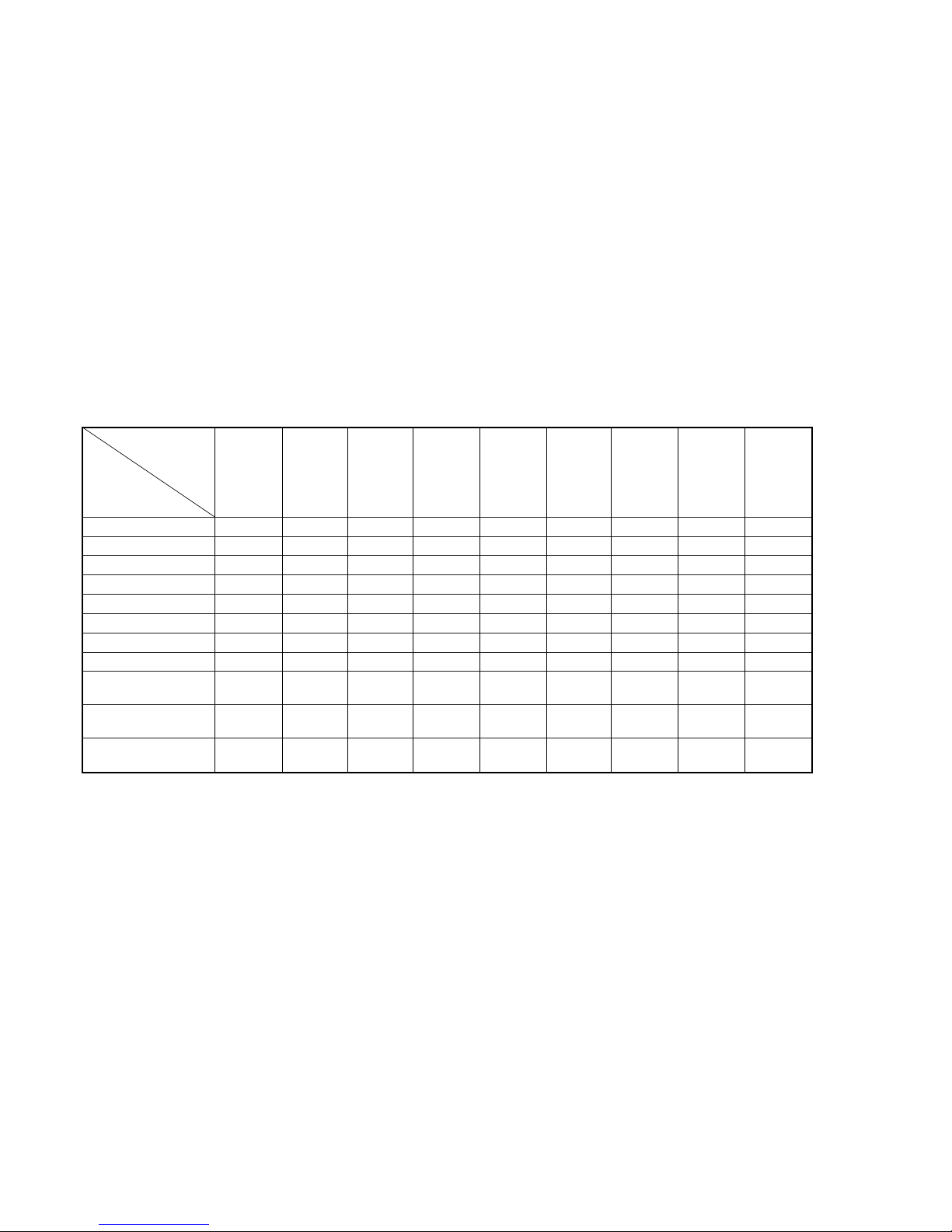
• Feature Difference
SLV- CA30TW GA35ME GA35PL GA55ME GA55PL GF85PL GF85PS GF85TW SP100R
GA35TW GA35PS GA55PS GF85TH
SA33TW GA35SG GA55SG
GA35TH GA55TH
SP70R
Feature
HEAD/CH 2/2 2/2 2/2 4/4 4/4 6/6 6/6 6/6 4/4
NTSC (3.58) (REC/PB) ×/a ×/××/aa/aa/aa/aa/aa/aa/a
(4.43) (REC/PB) ×/××/a ×/× a/a ×/××/× a/a ×/× a/a
MESECAM (REC/PB) ×/a ×/a ×/aa/aa/a ×/× a/a ×/× a/a
REC (NTSC) (SP/EP) ×/××/××/× a/aa/aa/aa/× a/aa/×
(PAL) (SP/LP) ×/××/××/× a/aa/a ×/× a/××/× a/×
PLAY (NTSC) (SP/EP) a/aa/aa/aa/aa/aa/aa/× a/aa/×
(PAL) (SP/LP) a/aa/aa/aa/aa/a ×/× a/××/× a/×
RCA LINE IN/OUT ×/a (2P) ×/a (2P) ×/a (2P) a (2P)/ a (2P)/ a (3P)/ a (3P)/ a (3P)/ a (3P)/
a (2P) a (2P) a (3P) a (3P) a (3P) a (3P)
MODULATOR
SYSTEM
13ch G/K 3/4ch G/K 3/4ch 3/4ch G/K 13ch G/K
REMOTE
COMMANDER
RMT-V286C RMT-V286A RMT-V286A RMT-V286 RMT-V286 RMT-V286 RMT-V286 RMT-V286B RMT-V286

– 3 –
TABLE OF CONTENTS
Section Title Page Section Title Page
Feature Difference................................................................... 2
SERVICE NOTE ...................................................................... 4
1. GENERAL
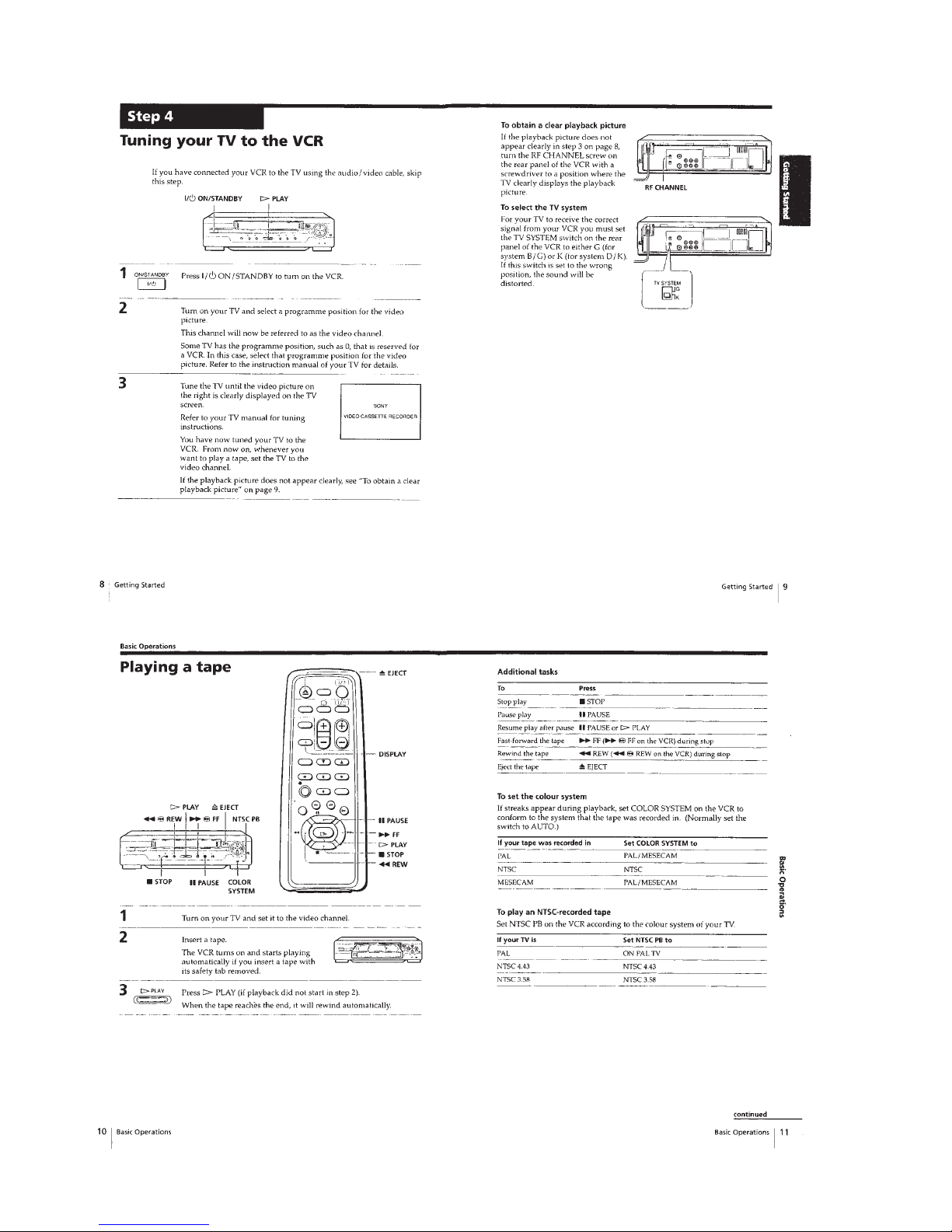
Getting Started .............................................................. 1-1
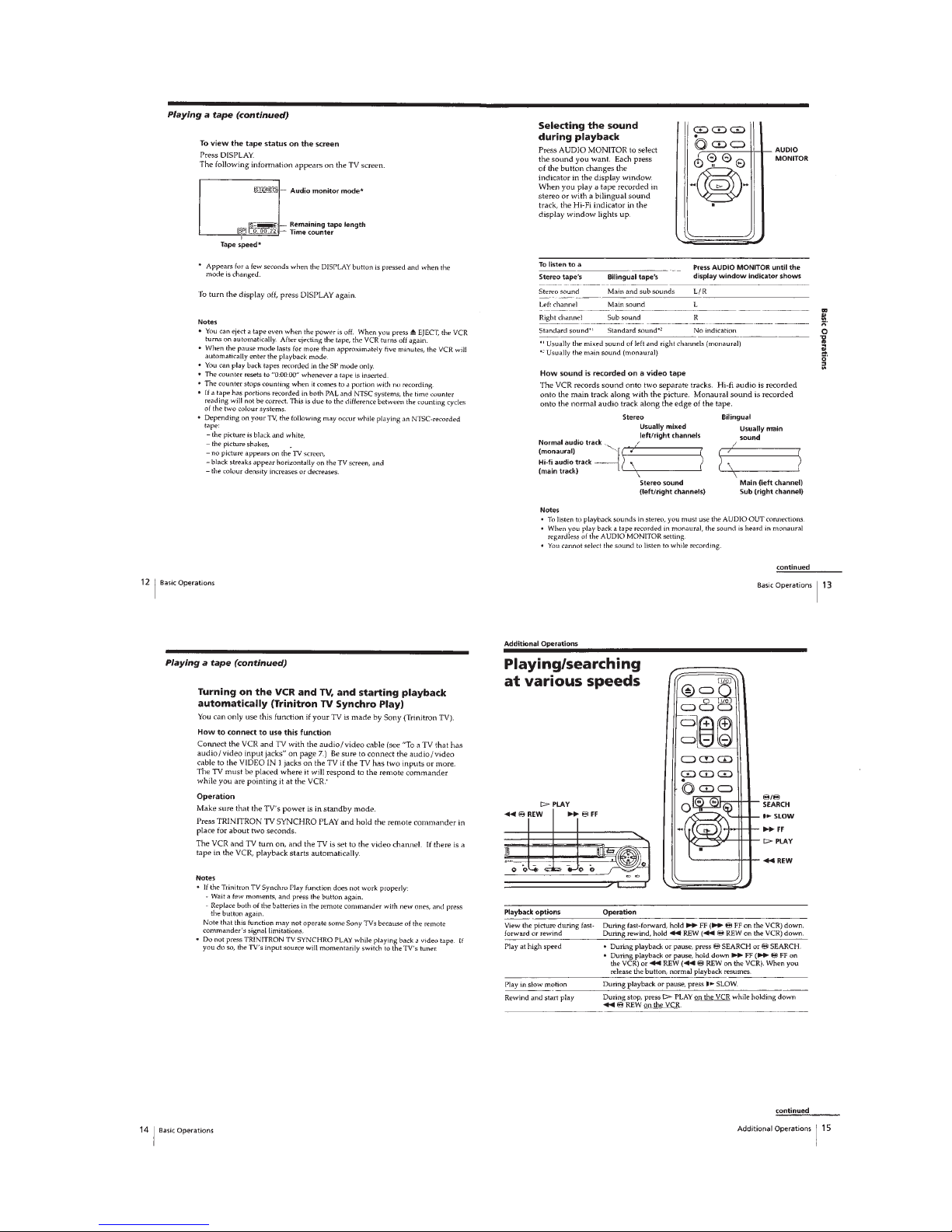
Basic Operations ........................................................... 1-2
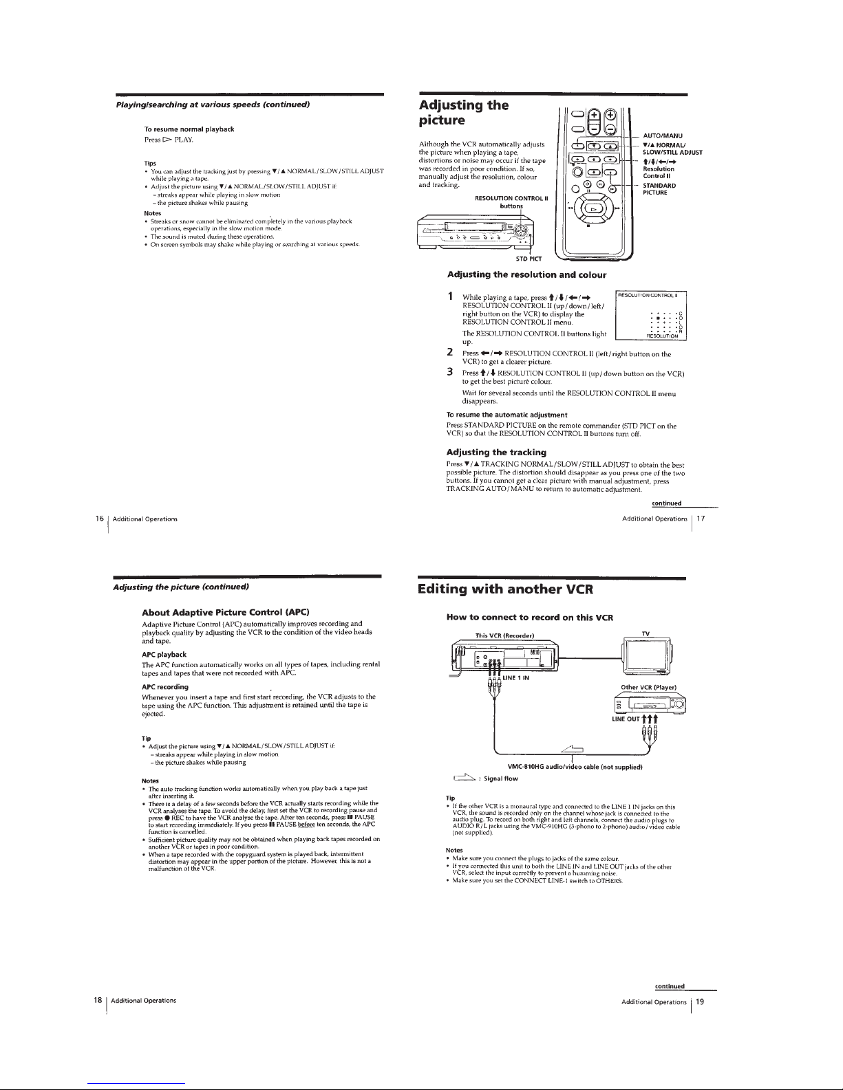
Additional Operations.................................................... 1-3
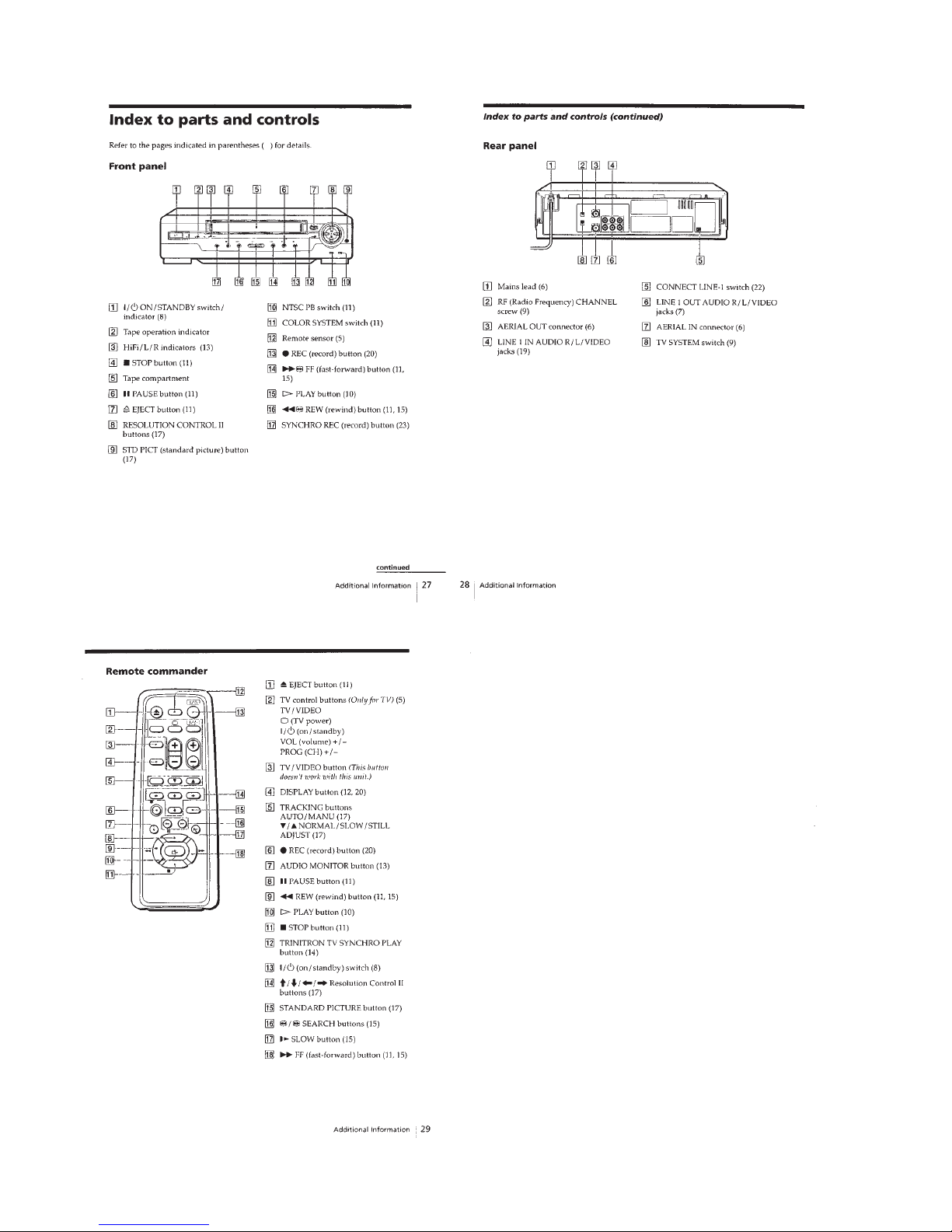
Additional Information ................................................... 1-6
2. DISASSEMBLY
2-1. Upper Case Removal .................................................... 2-1
2-2. Front Panel Section Removal........................................ 2-1
2-3. Rear Panel Removal ..................................................... 2-1
2-4. Mechanism Deck Removal............................................ 2-1
2-5. MA-366 Board Removal ................................................ 2-2
2-6. Internal Views ................................................................ 2-3
2-7. Circuit Boards Location ................................................. 2-4
3. BLOCK DIAGRAMS
3-1. Overall Block Diagram................................................... 3-1
3-2. Video Block Diagram..................................................... 3-3
3-3. Servo/System Control Block Diagram .......................... 3-5
3-4. Audio Block Diagram ..................................................... 3-7
3-5. Mode Control Block Diagram ........................................ 3-9
3-6. Power Block Diagram .................................................... 3-11
4. PRINTED WIRING BOARDS AND
SCHEMATIC DIAGRAMS
4-1. Frame Schematic Diagram............................................ 4-3
4-2. Printed Wiring Boards and Schematic Diagrams ......... 4-5
MA-366 Printed Wiring Board ....................................... 4-5
MA-366 (Video, Audio) Schematic Diagram................. 4-9
MA-366 (OSD, Servo/System/Mode Control)
Schematic Diagram ....................................................... 4-13
MA-366 (HiFi Audio, I/O, TUNER)
Schematic Diagram ....................................................... 4-15
MA-366 (Power Supply) Schematic Diagram ............... 4-17
FR-167 Printed Wiring Board and
Schematic Diagram ....................................................... 4-19
5. INTERFACE, IC PIN FUNCTION DESCRIPTION
5-1. System Control-Video Block Interface
(MA-366 BOARD IC101)............................................... 5-1
5-2. System Control-Servo Peripheral Circuit Interface
(MA-366 BOARD IC101)............................................... 5-1
5-3. System Control-Mechanism Block Interface
(MA-366 BOARD IC101)............................................... 5-2
5-4. System Control-Audio Block Interface
(MA-366 BOARD IC101)............................................... 5-3
5-5. Servo/System Control Microprocessor
Pin Function (MA-366 BOARD IC101) ......................... 5-4
6. ADJUSTMENTS
6-1. Mechanical Adjustments ............................................... 6-1
6-2. Electrical Adjustments ................................................... 6-1
2-1. Pre-Adjustment Preparations ........................................ 6-1
2-1-1. Instruments to be Used............................................ 6-1
2-1-2. Connection ............................................................... 6-1
2-1-3. Set-up of Adjustment ............................................... 6-1
2-1-4. Alignment T apes....................................................... 6-1
2-1-5. Specified I/O Level and Impedance......................... 6-1
2-1-6. Adjusting Sequence ................................................. 6-2
2-2. Power Supply Adjustments ........................................... 6-2
2-2-1. Power Supply Check................................................ 6-2
2-3. Servo System Adjustments ........................................... 6-2
2-3-1. RF Switching Position Adjustment........................... 6-2
2-4. Audio System Adjustments ........................................... 6-3
2-4-1. Hi-Fi Audio System Adjustment ............................... 6-3
1. AF Switching Position Adjustment ........................... 6-3
2-4-2. Normal Audio System Adjustment ........................... 6-3
1. ACE Head Adjustment ............................................. 6-3
2. E-E Output Level Check........................................... 6-3
2-5. Parts Arrangement Diagram for Adjustments ............... 6-4
7. REPAIR PARTS LIST
7-1. Exploded Views ............................................................. 7-1
7-1-1. Front Panel and Cabinet Assemblies....................... 7-1
7-1-2. Chassis Assembly.................................................... 7-3
7-1-3. Mechanism Chassis Assembly (1)........................... 7-4
7-1-4. Mechanism Chassis Assembly (2)........................... 7-5
7-1-5. Mechanism Chassis Assembly (3)........................... 7-6
7-2. Electrical Parts List ....................................................... 7-7
– 4 –
SERVICE NOTE
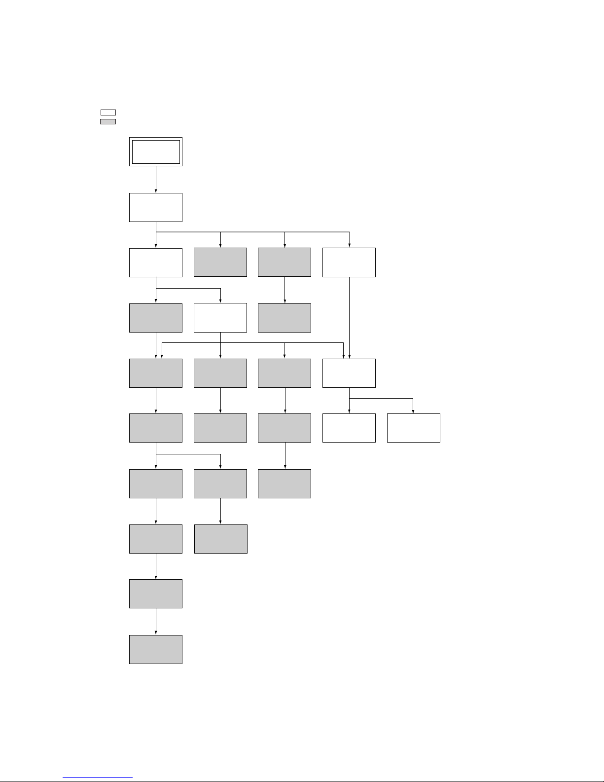
1. DISASSEMBLY
• This set can be disassembled in the order shown below.
Note: Pages in indicated pages in the SERVICE MANUAL.
Pages in indicated pages in the VHS MECHANICAL ADJUSTMENT MANUAL VI.
Set
Upper case
(Page 2-1)
Front Panel
Section
(Page 2-1)
Pinch Press
Block Ass’y
(Page 14)
Ground Shaft
Ass’y
(Page 13)
Mechanism
Deck
(Page 2-1)
FL Complete
Ass’y
(Page 13)
Drum
Ass’y
(Page 13)
Rear
Panel
(Page 2-1)
Rubber
Belt
(Page 15)
Rubber
Belt
(Page 15)
Slider
(Page 26)
Loading
Gear (T, S)
(Page 28)
Retainer
Plate
(Page 22)
MA-366
Board
(Page 2-2)
Rubber
Belt
(Page 15)
Capstan
Motor
(Page 15)
FL Slider
Block Ass’y
(Page 22)
Rotary
Switch
(Page 2-2)
Tuner
Unit
Pully Gear
Ass’y
(Page 29)
Cam Motor
Retainer
(Page 31)
Cam Gear
(Page 23)
Cam Motor
(Page 31)
Reel Direct
Ass’y
(Page 30)
1-1
SECTION 1
GENERAL
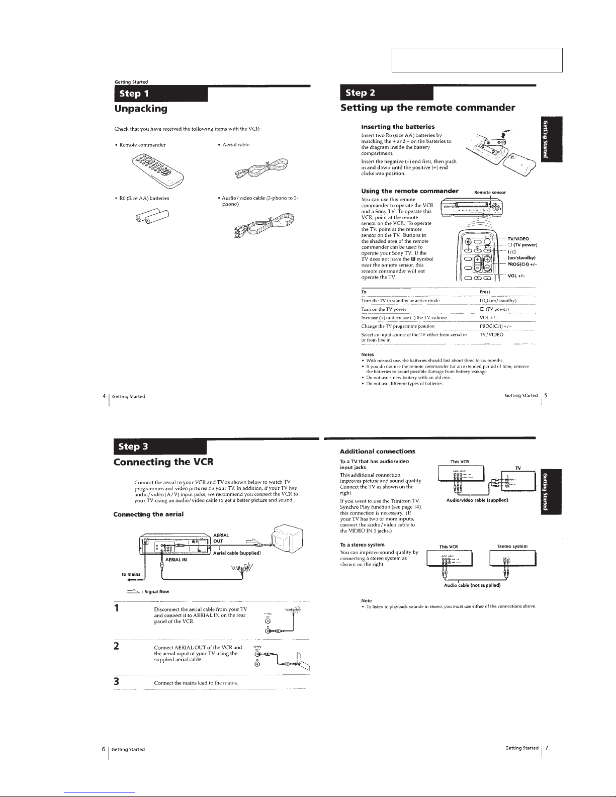
This section is extracted from SLV-SP100
instruction manual. (3-867-581-11)
SLV-CA30/GA35/GA55/GA65/GF85/SA33/SP70/SP100
1-2
1-3
1-4

1-5
1-6
1-6 E

2-1
Note: Follow the disassembly procedure in the numerical order given.
2-1. UPPER CASE REMOVAL 2-3. REAR PANEL REMOVAL
2-2. FRONT PANEL SECTION REMOVAL 2-4. MECHANISM DECK REMOVAL
SECTION 2
DISASSEMBLY
1 Two U/C screws
2 Two U/C screws
3 Upper case
4 Two U/C insulators
2 Two claws
3 Claw
5 Claw
1 Flat cable
(CN401)
4 Two claws
6 Front panel section
3 Screw
(BVTP3 × 12)
7 Rear panel
6 Two claws
4 Two claws
5 Three claws
1 Harness
2 Power cord
6 Screw
(BVTP3 × 12)
5 Screw
(BVTP3 × 12)
8 Screw
(BVTP3 × 12)
7 Earth lug
4 Flexible
board
(CN201)
9 Mechanism deck
2 Connector
(ACE head)
3 Connector
(FE head)
1 Flat cable
Note: When mounting the mechanism deck,
first align f mark on the rotary switch.
SLV-CA30/GA35/GA55/GA65/GF85/SA33/SP70/SP100
2-2
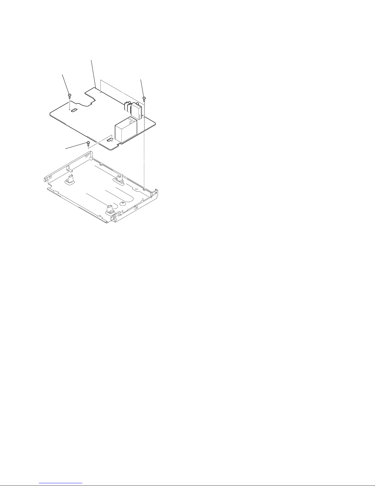
2-5. MA-366 BOARD REMOVAL
3 Two screws
(B3)
2 Screw (B3)
1 Screw
(B3)
4 MA-366 board
2-3
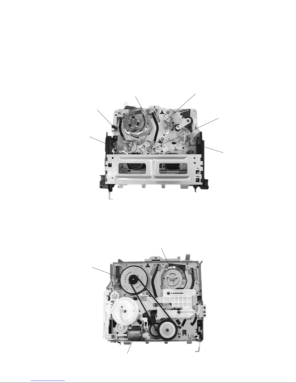
2-6. INTERNAL VIEWS
Drum assembly (M901) (DZH-71E-R)
1-772-147-11 (CA30/GA35TW/SA33)
Drum assembly (M901) (DZH-89B-R)
1-772-148-11 (GA35: ME, PL, PS, SG,TH/GA55/GA65/SP70)
Drum assembly (M901) (DZH-91B-R)
1-772-149-11 (GF85: PS, TH/SP100)
Drum assembly (M901) (DZH-90B-R)
1-772-351-11 (GF85: PL, TW)
Capstan motor
1-698-971-11
Cam motor assembly
X-3947-577-1
Q002
Tape top sensor
8-729-042-88
ACE head assembly
A-6759-620-A
FE head
1-500-144-11
Drum assembly (M901) (DZH-71E-R)
1-772-147-11 (CA30/GA35TW/SA33)
Drum assembly (M901) (DZH-89B-R)
1-772-148-11 (GA35: ME, PL, PS, SG, TH/GA55/GA65/SP70)
Drum assembly (M901) (DZH-91B-R)
1-772-149-11 (GF85: PS, TH/SP100)
Drum assembly (M901) (DZH-90B-R)
1-772-351-11 (GF85: PL, TW)
Q001
Tape end sensor
8-729-042-88
D001
Tape top/end LED
8-719-048-26

2-4
2-7. CIRCUIT BOARDS LOCATION
2-4 E
FR-167
(MODE CONTROL)
MA-366
VIDEO, AUDIO,
I/O, SERVO/SYSTEM CONTROL
()

SLV-CA30/GA35/GA55/GA65/GF85/SA33/SP70/SP100
3-1 3-2
SECTION 3
BLOCK DIAGRAMS
3-1. OVERALL BLOCK DIAGRAM
M
ROTARY
SWITCH
CAM
MOTOR
M902
M901
M903
LED
DRIVER
S REEL
IC101
VIDEO OUT
OSD
NA OUT
IC201
NORMAL
AUDIO
PROCESSOR
BIAS
ERASE
OSC
T371, Q372-374
AUDIO
ERASE
FULL
ERASE
L
R
AUDIO
VIDEO
LINE-1 IN
J901
RFU901
MOD V
MOD A
GA55, GA65,
SP70
RF SWP, V CLOCK, V DATA,
QVD, SHARPNESS
T REEL
PH001
T REEL FG
PH002
S REEL FG
IC201
+12V
IC101
SERVO/SYSTEM
CONTROL,
MODE CONTROL
Q013
D001
T/S LED
Q001
T SENS
Q002
S SENS
END LED
S SENS
T SENS
MESECAM, V ENV,
KILL, C SYNC
REMOTE
COMMANDER
RECEIVER
IC501
REMOCON
CTL
HEAD
CTL (+)
CTL (–)
M
PG/FG
PICK UP
DRUM PG
DRUM FG
DRUM VS
DRUM
MOTOR
MODE 1-4
CAM
M
FG
PICK UP
CAM
MOTOR
DRIVER
CAP FG
CAP VS
CAPSTAN
MOTOR
(REC PROOF)
S101
S102
IC102
RESET
RESET
SP
CH1
SP
CH2
VIDEO
HEAD
AUDIO
HEAD
(HiFi)
CH1
CH2
(MONO)
AUDIO
REC/PB
NA OUT
A MUTE
IC031
MA-366 BOARD
(SEE PAGE 4-9 to 4-17)
VIDEO REC/PB AMP,
Y/C PROCESSOR
(1/2)
(2/2)
M+12V
+9V
+5V
D+5V
(1/2)
+12V
L OUT, R OUT
S CLK, S DATA
AF SWP, AF ENV
NA IN
IC301
Hi-Fi
AUDIO
PROCESSOR
L IN,
R IN
RF OUT
BIAS
SWITCH
Q375-377
EXCEPT CA30/GA35/SA33
CA30/GA35/SA33
L
R
AUDIO
VIDEO
LINE-1 OUT
J901
(2/2)
EXCEPT
GF85/SP100
EXCEPT
GF85/SP100
L OUT
R OUT
V OUT
TV/VTR
EXCEPT CA30/GA35/SA33
GF85/SP100
GF85/SP100
GF85/SP100
RF SWP, V CLOCK, V DATA,
QVD, SHARPNESS
MESECAM, V ENV,
KILL, C SYNC
REC P
LED
DRIVER
D+5V
D+5V
FUNCTION
SWITCH
FR-167 BOARD
(SEE PAGE 4-20)
KEY 4
FUNCTION
SWITCH
D+5V
KEY 1-3
LED
DRIVER
F601
+9V REG
+5V REG
PS602
T601
POWER
TRANS
IC601
+B ADJ
IC103
PS601
JS353
JS352
JS351
+12V
Q604
05
D+5V
JS371

SLV-CA30/GA35/GA55/GA65/GF85/SA33/SP70/SP100
3-3 3-4
3-2. VIDEO BLOCK DIAGRAM
79
78
76 75 73 71 64 63 62 60 58 57 55 52
81
84
86
87
88
93
94
LOGIC
HEAD SW1
HEAD SW2
ENV DET
HPF
89
91
92
CH2
VCA
CH1
CH2
CH1
SW30
SW31
SP
SP
REC
MUTE
1/2
2EL VCO
PB/REC
DISCRI
REC
AFC
REC
AFCPBAPC
COLOR KILLER
IO DET
DOWN
CONV
X-TAL
VCO/OSC
CR DET
2FSC
69
2FSC
VCO
LC VCO
SERIAL CONT
INTERFACE
L-
SECAM
L-SECAM
SW27
SW28
LPF
2M LPF
1/2
PHASE VCO
P
R
SW20
ACC
SEP
COMP
SW19
HPF
CTL TRAP
HPF
FH TRAP
TRAP
P
R
SW18
VCA
CCD
LPF
DELAY CLPF
CLPF
DL R
SW25
PR
SW24
MAIN
CONV1
4PHASE GEN
MAIN
CONV2
SW21
P
R
SW22
RRP
P
SW23
B.D
N P
C.K
BPF
B.EC.K
MIX
LEVEL ADJ
PULSE
GEN
6dB AMP
SYNC. SEP
CLEAR
SYNC
SQUELCH
50
51
FEED BACK
CLAMP
VIDEO ALC
PICTURE
CONT.
P
R
SW17
DE
N.C
R
P
SW13
N.L
DE. EMPH
N.L
EMPH
FBC/ALC
Y-LPF
R
P
SW11
18
P
R
SW10
MAIN
DE-EMPH
16
SW9
MAIN EMPH
CARRIER OFFSET
W.C/DC
FO/EEV ADJ
S-DET
FM MOD
L.P.F.
7MHPF
1MHPF
FM AGC
629
TRAP
P
R
SW7
SUB LPF
DEMO
DLIM
G
EQ
17
EDGE
DELAYDODET
YNR
SW14
DO
DO
REC
CLAMP CLAMP
19 21 23
VIDEO AGC
ATT
(-10dB)
31
ATT
(-10dB)
ATT
(-10dB)
2624
L.P.F.
C-CCD Y-CCD
CLOCK
DRIVER
MODE
CONTROL
37
35
39
42
44
46
CCD
SW29
R
P
SW26
SW16
P
EQ
MMS
DL
SQPB
SQPB
SW8
2
2
6
1
3
NTSC
SWITCH
Q204
PAL
SWITCH
Q203
L.P.F.
BUFF
Q262
+
+
SHARP 2
SHARP 1
REC P
SHARPNESS
X201
4.43MHz
X202
3.58MHz
AFC FILTER SWITCH
Q202
RF SWP
V ENV
V DATA
V CLOCK
SERVO/SYSTEM
CONTROL
(SEE PAGE 3-5)
C SYNC
QVD
KILL
SERVO/SYSTEM
CONTROL
(SEE PAGE 3-5)
SERVO/SYSTEM
CONTROL
(SEE PAGE 3-5)
VIDEO REC/PB AMP,
Y/C PROCESSOR
SP
CH2
SP
CH1
CN201
SP CH2
SP COM
SP CH1
CHECK
MA-366 BOARD (1/4)
(SEE PAGE 4-9 to 4-15)
05
CN202
PB RF
V SWP
L372,C382,
R381,Q378
97
IC201 (1/2)
SP2
SP2
SP1
SP1
+
–
+
–
+
–
+
–
EP2
EP2
+
–
+
–
EP1
EP1
+
–
+
–
2
4
IN
OUT
RFU901
1
TV/VTR
AUDIO
VIDEO
TV/VTR
MODE CONTROL
(SEE PAGE 3-9)
AUDIO
AUDIO
(SEE PAGE 3-8)
5
SP COM
54
6dB AMP
C-SQUELCH
BUFF
Q205
SHARPNESS
CONT
Q261
SHARPNESS
CONT
Q263
PAL
NTSC
MESECAM
CHROMA
CONTROLLER
Q290-293
BURST GATE
GENERATOR
Q294-299
CHROMA 4
CHROMA 3
CHROMA 2
CHROMA 1
52
43
55
45
IC101
(1/3)
OSD
OSD
53
2fsc
AMP
Q266
BUFF
Q264, 267
SWITCH
Q265
BUFF
Q901
J901
VIDEO
LINE-1
OUT
SERVO/SYSTEM
CONTROL
(SEE PAGE 3-5)
NTSC/PAL
N-P CONT
OUT
BUFF
Q201
EXCEPT CA30/GA35: PL, TW/GA55PL/
GF85: PL, TW/SA33
EXCEPT GA35:ME,PS,SG,TH
EXCEPT CA30/GA35: PL, TW/GA55PL/
GF85: PL, TW/SA33
EXCEPT CA30/GA35: PL, TW/
GA55PL/GF85: PL, TW/SA33
EXCEPT CA30/GA35/SA33
CA30/GA35/SA33
LINE-1
IN
VIDEO
IC201ih, ij, ik, il REC
1.8Vp-p (H)
IC201ul PB
450mVp-p (H) (PAL)
780mVp-p (H) (NTSC)
IC201ul PB
320mVp-p (H) (PAL)
580mVp-p (H) (NTSC)
IC201ug REC/PB
520mVp-p (4.43MHz) (PAL)
IC201ua REC/PB
510mVp-p (3.58MHz) (NTSC)
IC201y; REC/PB
340mVp-p (H) (PAL)
IC201y; REC/PB
REC:300mVp-p (H) (NTSC)
PB:290mVp-p (H) (NTSC)
IC201tk REC/PB
500mVp-p (H) (PAL)
IC201tk REC/PB
440mVp-p (H) (NTSC)
IC201t; REC/PB
5.0Vp-p (H)
IC201ea REC/PB
1.1Vp-p (H) (NTSC)
IC201ea REC/PB
1.1Vp-p (H) (PAL)
IC101rd, rg REC/PB
2.2Vp-p (H) (PAL)
IC101rd, rg REC/PB
2.2Vp-p (H) (NTSC)
IC201wd REC/PB
REC:390mVp-p (H) (PAL)
PB:500mVp-p (H) (PAL)
REC:400mVp-p (H) (PAL)
PB:580mVp-p (H) (PAL)
REC:510mVp-p (H) (NTSC)
PB:560mVp-p (H) (NTSC)
REC:480mVp-p (H) (NTSC)
PB:550mVp-p (H) (NTSC)
IC201wd REC/PBIC201qk, ql REC/PB IC201qk, ql REC/PB
IC201wh REC/PB
IC201wh REC/PB
REC:500mVp-p (H) (PAL)
PB:600mVp-p (H) (PAL)
REC:620mVp-p (H) (NTSC)
PB:690mVp-p (H) (NTSC)
REC:400mVp-p (H) (NTSC)
PB:450mVp-p (H) (NTSC)
IC201wa REC/PB
IC201wa REC/PB
REC:320mVp-p (H) (PAL)
PB:430mVp-p (H) (PAL)
 Loading...